Integrating SCADA RTUs and Controllers into DeltaV TM · DeltaV RTU Connect into the DeltaV...
24
White Paper April 2014 DeltaV RTU Connect D351498X412 Integrating SCADA RTUs and Controllers into DeltaV TM This white paper describes the integration support of Emerson’s SCADA RTUs and flow computers into a DeltaV DCS System. DeltaV RTU Connect is a software solution from Emerson’s Process Systems and Solutions and Remote Automation Solutions business units that integrates SCADA and DCS data, connecting field-based RTUs (SCADA system) with a plant DCS system. DeltaV RTU Connect propagates real-time data, alarms, and historical logged data from the OpenEnterprise ™ SCADA system to the DeltaV DCS system. DeltaV RTU Connect leverages OpenEnterprise telemetry communications, along with open connectivity standards for bi-directional data transfer (i.e. RTU data through to DeltaV, DCS control commands back to the RTU).
Transcript of Integrating SCADA RTUs and Controllers into DeltaV TM · DeltaV RTU Connect into the DeltaV...

White PaperApril 2014
DeltaV RTU ConnectD351498X412
Integrating SCADA RTUs and Controllersinto DeltaV TM
This white paper describes the integration support of Emerson’s SCADA RTUs and flow computers into a DeltaV DCS System.
DeltaV RTU Connect is a software solution from Emerson’s Process Systems and Solutions and Remote Automation Solutions business units that integrates SCADA and DCS data, connecting field-based RTUs (SCADA system) with a plant DCS system. DeltaV RTU Connect propagates real-time data, alarms, and historical logged data from the OpenEnterprise™ SCADA system to the DeltaV DCS system.
DeltaV RTU Connect leverages OpenEnterprise telemetry communications, along with open connectivity standards for bi-directional data transfer (i.e. RTU data through to DeltaV, DCS control commands back to the RTU).

DeltaV RTU Connect
2 www.EmersonProcess.com/Remote
April 2014
Table of Contents1. Introduction .................................................. 1
2. DeltaV RTU Connect Physical Architecture .... 4
2.1 ProfessionalPLUS Workstation ............. 4
2.2 Operator Workstation ......................... 5
2.3 Application Station .............................. 5
2.4 DeltaV Controller ................................ 5
2.5 Virtual Controller ................................ 5
2.6 OpenEnterprise ................................... 6
2.7 Plantwide Event Historian (PEH) .......... 6
2.8 PI Historian and PI Client ..................... 6
2.9 OPC Mirror and Data Access ................ 6
2.10 Remote Controllers ............................. 7
3. Real-Time Data Integration ............................ 7
3.1 The OPC Mirror ................................... 8
3.2 The OpenEnterprise OPC Server .......... 8
3.3 The DeltaV OPC Server ........................ 8
3.4 Virtual Controller ................................ 8
3.5 OpenEnterprise ................................... 8
3.6 Communication Drivers ...................... 8
3.6.1 The ControlWave™ Driver .......... 9
3.6.2 The ROC Driver ..................... 9
3.7 RTU Polling ......................................... 9
4. Historical Logging Systems ............................ 9
4.1 Continuous Historian .......................... 9
4.2 PI Historian Backfi ll Operation ............. 10
5. Alarm and Events Logging System ................. 12
5.1 Event Chronicle ................................... 12
5.2 Plant Event Historian (PEH) .................. 13
6. The DeltaV RTU Connect Confi guration Tool .. 14
6.1 User Interface ..................................... 14
6.2 Historical Confi guration User Interface .. 15
6.3 Confi guration Output Files .................. 16
6.4 Virtual Controller Confi guration .......... 16
6.5 OPC Mirror Confi guration .................... 17
6.6 Command Line Usage ......................... 17
7. Performance Benchmarking .......................... 18
8. Compatibility ................................................ 18
9. Ordering Information .................................... 18
10. Appendix A ................................................... 19
10.1 .FHX Schema ....................................... 19
www.EmersonProcess.com/Remote 3
DeltaV RTU ConnectApril 2014
Key Features
Enables wide area telemetry solution for DeltaV Provides an easy-to-use drag-and-drop confi guration tool that does not require any programming Provides seamless transfer of RTU real-time data to DeltaV Provides seamless transfer of DCS commands to RTUs Generates alarms directly in DeltaV Operator workstations Provides seamless transfer RTU alarm defi nitions and confi gurations to DeltaV Centralizes logging of selected SCADA Alarms in DeltaV PEH Historian Centralizes logging of selected SCADA Historical points in PI Historian Provides automatic backfi ll to DeltaV PI Historian in the event of RTU communication lossPreserves local timestamps of all RTU data in DeltaV
The diagram below represents the functional architecture of DeltaV RTU Connect. Although the DeltaV RTU Connect is installed on the Application Station, functionally the DeltaV DCS system recognizes the solution as a virtual controller (on the same level as the actual physical hardware controllers).
DeltaV RTU Connect Solution
Provides real-time bi-directional pass-through between Emerson’s RTUs and DeltaVGenerates real-time alarms as current alarms on the DeltaV Operator StationLogs system historical logged data to the PI historianLogs system alarm and event data to PEH historian
DeltaV RTU Connect
4 www.EmersonProcess.com/Remote
April 2014
2. DeltaV RTU Connect Physical ArchitectureThe following graphic presents the overall design of the DeltaV RTU Connect solution and shows how it fi ts into a standard DeltaV network. DeltaV RTU Connect enables you to integrate RTU data into a DeltaV system using the following DeltaV components.
A complete DeltaV RTU Connect solution includes the following components:
ProfessionalPLUS (ProPLUS) workstation: the central DCS node for system management Operator Station(s): end user workstations DeltaV controllers: in-plant hardware controllers Application Station: installed with OpenEnterprise which collects data from RTUs A second Application Station running OSISoft PI historian as the historical database and the Plant Wide Event Historian
(PEH) for alarm and event history data from the RTUs Virtual Controller – which makes data from RTUs available to the entire DeltaV system OPC Mirror Remote Controllers and RTUs (Remote Automation Solutions products)
2.1 ProfessionalPLUS WorkstationThe ProfessionalPLUS (ProPLUS) workstation provides a single administrative point of entry, permitting access to all aspects of a DeltaV integrated system (including third-party applications). The ProPLUS workstation also contains the central DeltaV confi guration database. A ProPLUS workstation is a requirement of every DeltaV network. There can be only one ProPLUS workstation per system.
www.EmersonProcess.com/Remote 5
DeltaV RTU ConnectApril 2014
2.2 Operator WorkstationA DeltaV operator workstation provides standard plant operational view capability. This includes theuse of control displays, real-time and historical trending capabilities, and the ability to view and process alarms. As such, these workstations provide visibility of all SCADA related data and alarms brought in through the DeltaV RTU Connect.
2.3 Application StationThe Application Station integrates third-party software and applications into the DeltaV system. A single system can host up to 20 Application Stations, each with its own virtual controller. You can confi gure a desktop or server machine to be an Application Station within DeltaV system.
The DeltaV RTU Connect is installed on a DeltaV Application Station. Typically, you install the OpenEnterprise on one Application Station and install the Plantwide Event Historian and PI Historian on a separate Application Station.
2.4 DeltaV ControllerThe Application Station integrates third-party software and applications into the DeltaV system. A single system can host up to 20 Application Stations, each with its own virtual controller. You can confi gure a desktop or server machine to be an Application Station within DeltaV system.
The DeltaV RTU Connect is installed on a DeltaV Application Station. Typically, you install the OpenEnterprise on one Application Station and install the Plantwide Event Historian and PI Historian on a separate Application Station.
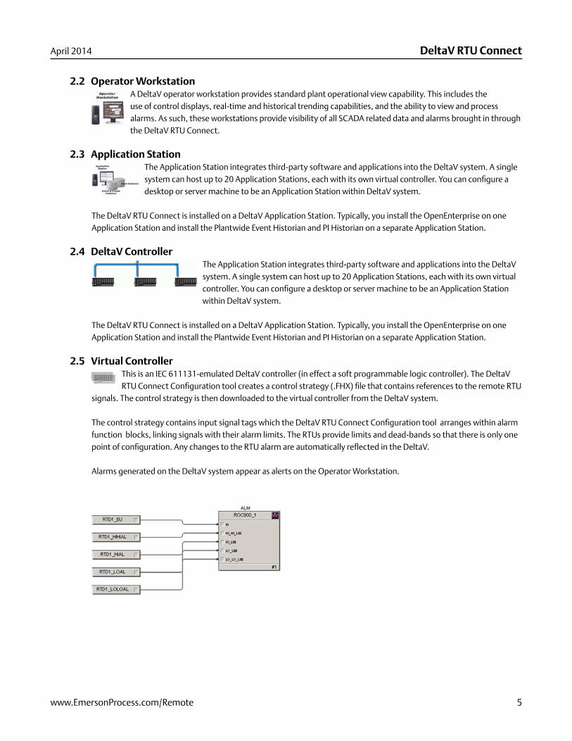
2.5 Virtual ControllerThis is an IEC 611131-emulated DeltaV controller (in effect a soft programmable logic controller). The DeltaV RTU Connect Confi guration tool creates a control strategy (.FHX) fi le that contains references to the remote RTU
signals. The control strategy is then downloaded to the virtual controller from the DeltaV system.
The control strategy contains input signal tags which the DeltaV RTU Connect Confi guration tool arranges within alarm function blocks, linking signals with their alarm limits. The RTUs provide limits and dead-bands so that there is only one point of confi guration. Any changes to the RTU alarm are automatically refl ected in the DeltaV.
Alarms generated on the DeltaV system appear as alerts on the Operator Workstation.
DeltaV RTU Connect
6 www.EmersonProcess.com/Remote
April 2014
2.6 OpenEnterpriseOpenEnterprise is Remote Automation Solutions’ SCADA system. It contains several components (Device Drivers, Communications Management, Real-time Database, Historian, Alarm Handling, Reporting, and Visualization). For DeltaV RTU Connect, you install a subset of the components:
Device Drivers (ROC, ROC Plus Protocol, and BSAP protocol)Communications management, modem, radio, satellite, IP network support Real-time database for propagation through to DeltaV Historian for backfi ll operation and transfer to DeltaVAlarm handling to transfer RTU alarms to DeltaV PEH historian
OpenEnterprise collects data from RTUs using direct low-level communications programs and serves the data to clients, normally through standard OPC and ODBC application interfaces.
2.7 Plantwide Event Historian (PEH)The Plantwide Event Historian (PEH) captures, stores, and displays event data for an entire plant. It records plant event information from any OPC Alarm and Event server (including the OpenEnterprise OPC Alarm and Event server)
and stores that information in a Microsoft SQL Server database.
2.8 PI Historian and PI ClientThe PI Historian is a standard enterprise database developed by OSIsoft™ that provides an embedded, centralized alternative to the native DeltaV continuous historian. The PI Historian can be installed onto an Application Station
and embedded into a DeltaV system.
DeltaV RTU Connect streams historical and backfi ll data from OpenEnterprise SCADA to the DeltaV PI Historian via the PI SDK client. DeltaV operator workstations are confi gured to request historical data from the PI Historian rather than the DeltaV continuous historian.
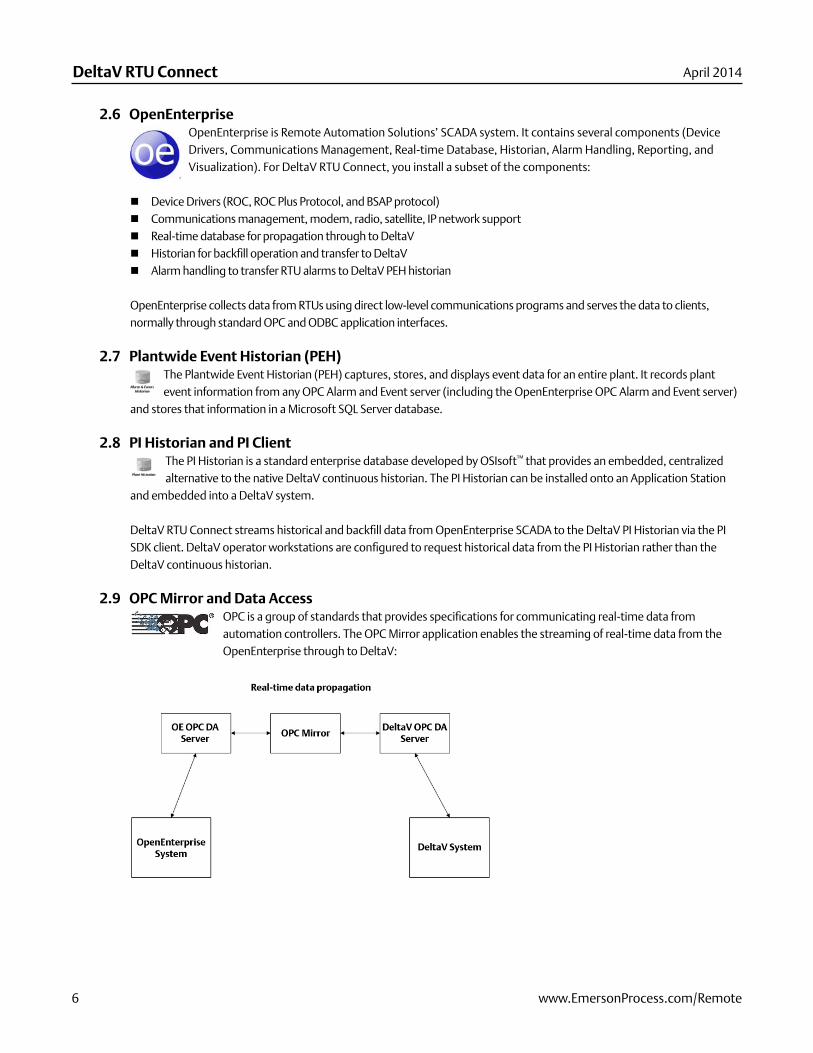
2.9 OPC Mirror and Data AccessOPC is a group of standards that provides specifi cations for communicating real-time data from automation controllers. The OPC Mirror application enables the streaming of real-time data from the OpenEnterprise through to DeltaV:
www.EmersonProcess.com/Remote 7
DeltaV RTU ConnectApril 2014
2.10 Remote ControllersThese are remote SCADA controllers (ControlWave, ROC, FloBoss™) that are integrated into the DeltaV system through the DeltaV RTU Connect. These controllers are designed for low power remote SCADA applications requiring telemetry over high latency, low bandwidth serial RF networks.
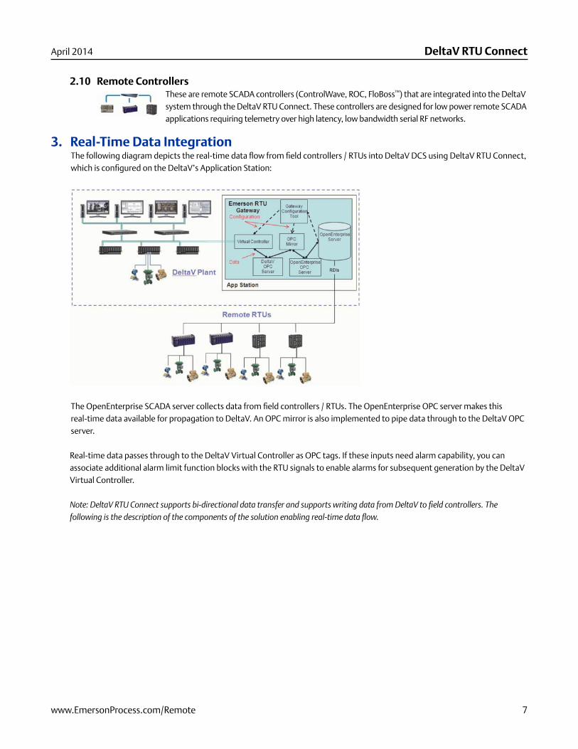
3. Real-Time Data IntegrationThe following diagram depicts the real-time data fl ow from fi eld controllers / RTUs into DeltaV DCS using DeltaV RTU Connect, which is confi gured on the DeltaV’s Application Station:
The OpenEnterprise SCADA server collects data from fi eld controllers / RTUs. The OpenEnterprise OPC server makes this real-time data available for propagation to DeltaV. An OPC mirror is also implemented to pipe data through to the DeltaV OPC server.
Real-time data passes through to the DeltaV Virtual Controller as OPC tags. If these inputs need alarm capability, you can associate additional alarm limit function blocks with the RTU signals to enable alarms for subsequent generation by the DeltaV Virtual Controller.
Note: DeltaV RTU Connect supports bi-directional data transfer and supports writing data from DeltaV to fi eld controllers. The following is the description of the components of the solution enabling real-time data fl ow.
DeltaV RTU Connect
8 www.EmersonProcess.com/Remote
April 2014
3.1 The OPC MirrorThe OPC Mirror creates a channel (“pipe”) that streams data between two OPC servers. To form a pipe, the OPC Mirror requires:
The program ID of the OpenEnterprise OPC server ( “A”)The program ID of the DeltaV OPC server ( “B”)The direction of the pipingFrom A to BFrom B to ABoth ways (this is the option that is supported for bi-directional data transfer)
A map of the required signal data
The system automatically creates these confi gurations when you export a .FHX fi le using the DeltaV RTU Connect Confi guration tool (see the section DeltaV RTU Confi guration Tool). The confi guration tool also sets up the OPC Mirror at this same time. You must, however, provide the correct DeltaV administrator user name and password (which was assigned to the Application Station during installation).
3.2 The OpenEnterprise OPC ServerTo provide for real-time logged data, the DeltaV RTU Connect uses OPC Data Access connectivity. The OpenEnterprise OPC Data Access server makes data from the OpenEnterprise database available to OPC clients. Its program ID is BristolBabcock.BristolOPCServer
3.3 The DeltaV OPC ServerThe DeltaV OPC Data Access server makes data from the Deltav RTU Connect available to the DeltaV Virtual Controller on the Application Station, which in turn makes it available to the rest of the DeltaV system. Its program ID is OPC.DeltaV.1
3.4 Virtual ControllerThe Virtual Controller inputs are connected to the OpenEnterprise OPC Data Access server via the OPC Mirror in order to receive real-time data from DeltaV RTU Connect. In this manner the Virtual Controller pushes data received from the DeltaV RTU Connect into the DeltaV network, thereby emulating pass-through real-time data and alarms from remote fi eld controllers and RTUs.
3.5 OpenEnterpriseOpenEnterprise is a leading edge SCADA that provides remote communications, telemetry and connectivity to Emerson RTUs and fl ow computers (such as ControlWave, ROC, or FloBoss) as part of the DeltaV RTU Connect solution. Typical applications requiring remote communications include oil and gas wellhead, transmission, and distribution.
OpenEnterprise collects data from ControlWave, ROC, or FloBoss devices using native communications drivers and serves the data to clients, through standard OPC and ODBC application interfaces.
3.6 Communication DriversOpenEnterprise communicates with ControlWave, ROC, and FloBoss using a set of device drivers called Remote Device Interfaces (RDIs). Collected data can consist of current values, history, and alarm and event data.
www.EmersonProcess.com/Remote 9
DeltaV RTU ConnectApril 2014
3.6.1 The ControlWave DriverThe ControlWave driver is also known as the NW3000 RDI, since it was originally created for the Network 3000 family of devices. The ControlWave RDI is installed as part of OpenEnterprise. The ControlWave RDI requires that you install OpenBSI on the same machine along with the ControlWave control application (“RTU Load”) and network defi nition fi les.
The ControlWave RDI confi guration program is the NW3000 Setup tool, which uses two other programs:
The NW3000 Signal Builder, which inserts, modifi es, and deletes signals from the databaseThe Template Builder, which creates polling templates from those signals for effi cient data collection
3.6.2 The ROC DriverThe ROC RDI (Remote Device Interface) is also installed as part of OpenEnterprise. It is a communications driver that enables OpenEnterprise to communicate with and collect data from ROC and FloBoss RTUs.
ROCLink is the confi guration tool which enables you to add ROC devices and points to the database and schedule data collection.
3.7 RTU Polling The frequency of real-time updates through the OPC Mirror is restricted by the rate at which OpenEnterprise can collect the data. In many cases where only a dial-up or serial RF connection exists, this may be once a day and/or on demand. At that time, the DeltaV RTU Connect obtains historical signal data from the RTUs and streams it to DeltaV.
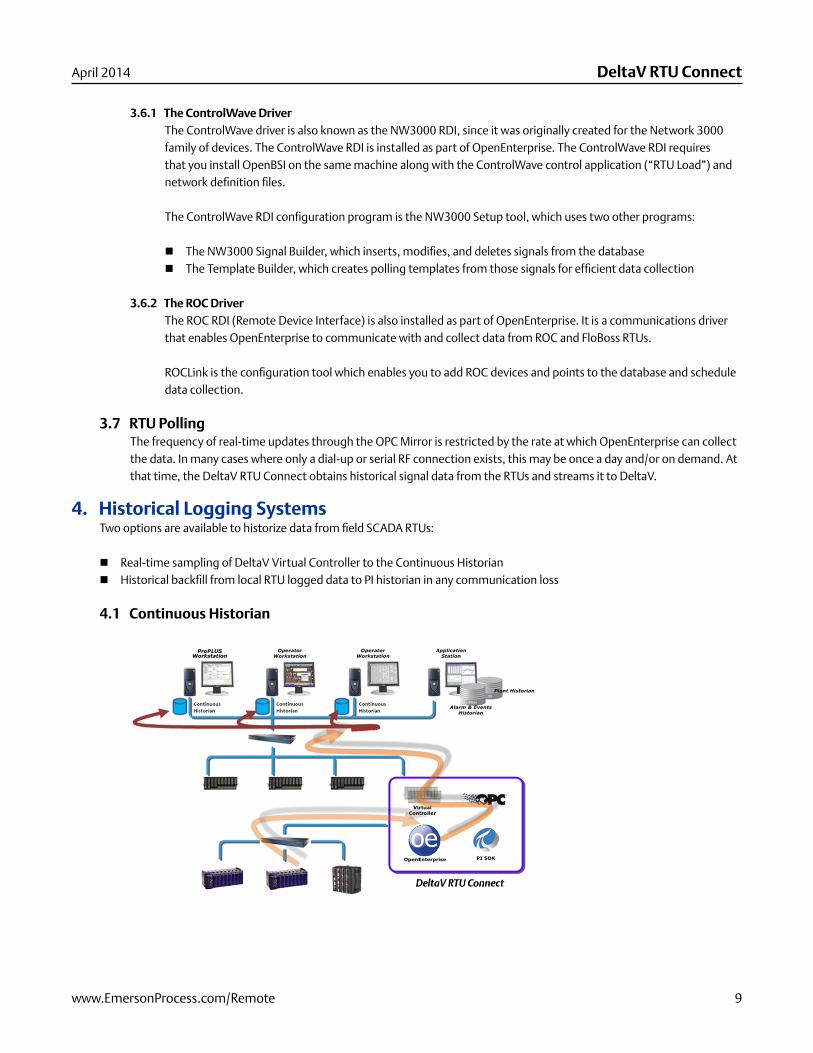
4. Historical Logging Systems Two options are available to historize data from fi eld SCADA RTUs:
Real-time sampling of DeltaV Virtual Controller to the Continuous Historian Historical backfi ll from local RTU logged data to PI historian in any communication loss
4.1 Continuous Historian
DeltaV RTU Connect
10 www.EmersonProcess.com/Remote
April 2014
Real-time data can be historized to the native DeltaV historian called the “Continuous Historian” based on the Emerson-owned “Objectivity” database. This database resides on each workstation as a separate historical instance and services the historical needs for that user such as trending. The historical logging mechanism is supported on any standard DeltaV system.
However, this approach is recommended only for permanently connected RTUs with robust communications (such as fi ber optic cable). In typical SCADA applications, the telemetry can be intermittent and prone to communication outages. Under such situations, the Continuous Historian is not recommended as there would be no means to handle device communication loss. For example, if you confi gured a ROC to store historical data within its archive and attached it to the system using non-robust communications, the pass through history collection defi ned above could not access and backfi ll the stored archive data during any period of downtime.
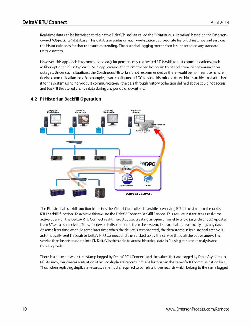
4.2 PI Historian Backfill Operation
The PI historical backfi ll function historizes the Virtual Controller data while preserving RTU time stamp and enables RTU backfi ll function. To achieve this we use the DeltaV Connect Backfi ll Service. This service instantiates a real-time active query on the DeltaV RTU Connect real-time database, creating an open channel to allow (asynchronous) updates from RTUs to be received. Thus, if a device is disconnected from the system, itshistorical archive locally logs any data. At some later time when At some later time when the device is reconnected, the data stored in its historical archive is automatically sent through to DeltaV RTU Connect and then picked up by the service through the active query. The service then inserts the data into PI. DeltaV is then able to access historical data in PI using its suite of analysis and trending tools.
There is a delay between timestamp logged by DeltaV RTU Connect and the values that are logged by DeltaV system (to PI). As such, this creates a situation of having duplicate records in the PI historian in the case of RTU communication loss. Thus, when replacing duplicate records, a method is required to correlate those records which belong to the same logged
www.EmersonProcess.com/Remote 11
DeltaV RTU ConnectApril 2014
timestamped data. The system accomplishes this by comparing incoming records with existing records based on user-confi gurable tolerance in the timestamp (which is 1 second by default). This mechanism forces the system to consider any records time-stamped up to 1 second on either side of the currently logged value as the same record.
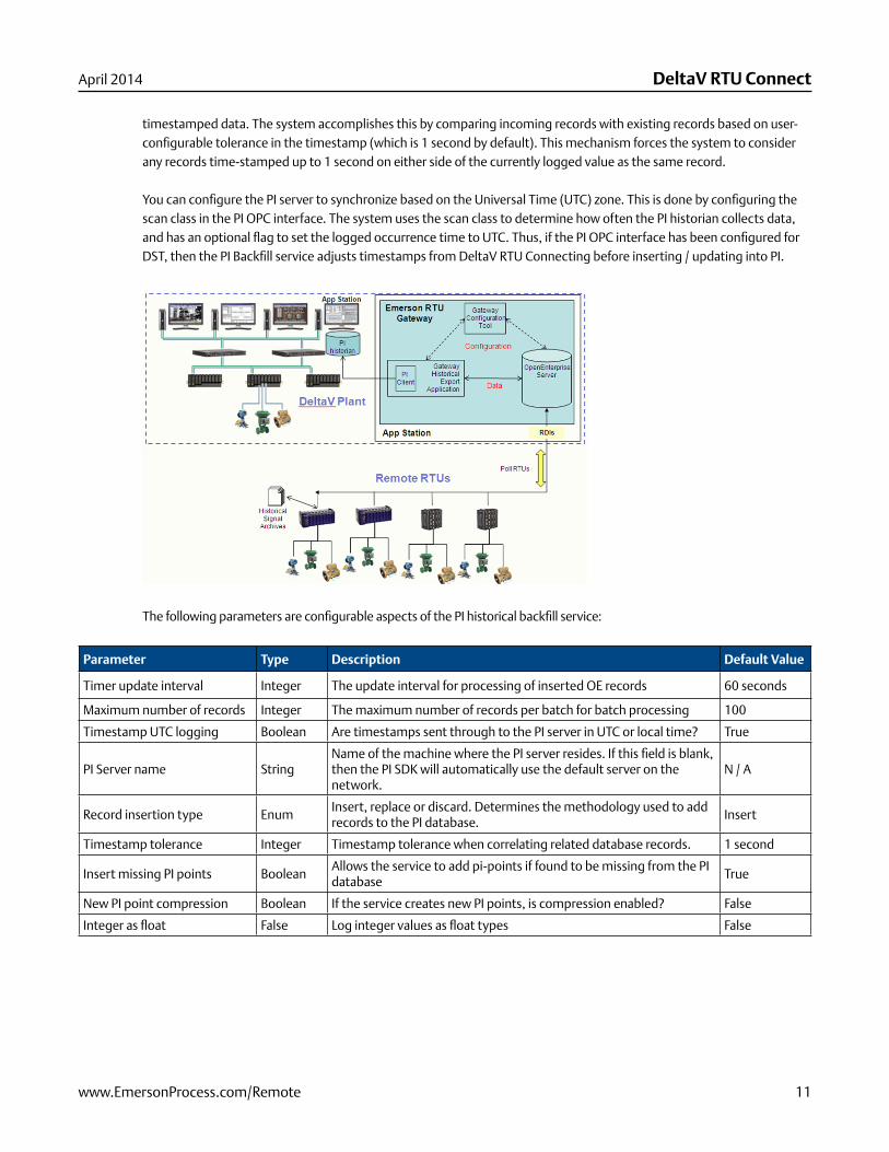
You can confi gure the PI server to synchronize based on the Universal Time (UTC) zone. This is done by confi guring the scan class in the PI OPC interface. The system uses the scan class to determine how often the PI historian collects data, and has an optional fl ag to set the logged occurrence time to UTC. Thus, if the PI OPC interface has been confi gured for DST, then the PI Backfi ll service adjusts timestamps from DeltaV RTU Connecting before inserting / updating into PI.
The following parameters are confi gurable aspects of the PI historical backfi ll service:
Parameter Type Description Default Value
Timer update interval Integer The update interval for processing of inserted OE records 60 seconds
Maximum number of records Integer The maximum number of records per batch for batch processing 100
Timestamp UTC logging Boolean Are timestamps sent through to the PI server in UTC or local time? True
PI Server name String Name of the machine where the PI server resides. If this fi eld is blank, then the PI SDK will automatically use the default server on the network.
N / A
Record insertion type EnumInsert, replace or discard. Determines the methodology used to add records to the PI database.
Insert
Timestamp tolerance Integer Timestamp tolerance when correlating related database records. 1 second
Insert missing PI points BooleanAllows the service to add pi-points if found to be missing from the PI database
True
New PI point compression Boolean If the service creates new PI points, is compression enabled? False
Integer as fl oat False Log integer values as fl oat types False
DeltaV RTU Connect
12 www.EmersonProcess.com/Remote
April 2014
Historical Backfi ll requires an instance of the OSIsoft PI database. This database needs to be confi gured as the Plant Wide Historian for all the operator workstations. In order to use the Backfi ll service, you must confi gure three system components:
1. Confi gure a historical storage within the RTU device. a. For ROC devices, use ROCLINK 800 to confi gure signals for historical storage within a history segment (Refer to the
ROCLINK 800 documentation).b. For ControlWave devices, confi gure an Archive module to store the required signal values historically. (Refer to the
ControlWave Designer or ACCOL documentation)2. Confi gure DeltaV RTU Connect to collect the historical data.
a. For ROC devices, consult the OpenEnterprise ROC Confi guration Tool Reference Guide (document number D301654x412).
b. For ControlWave devices, consult the OpenEnterprise NW3000 Archiving Overview Reference Guide (document number D301506x412) and the OpenEnterprise NW3000 Archive Confi guration Reference Guide (document number D301505x412).
3. Confi gure DeltaV to use the embedded PI Historian. For further help, see the DeltaV documentation.
5. Alarm and Events Logging SystemThe DeltaV RTU Connect uses following historians for generating and post analysis of alarms and events:
Event Chronicle that resides on the operator workstation as a local historian Plant Event Historian (PEH) centralizes all events on a single database
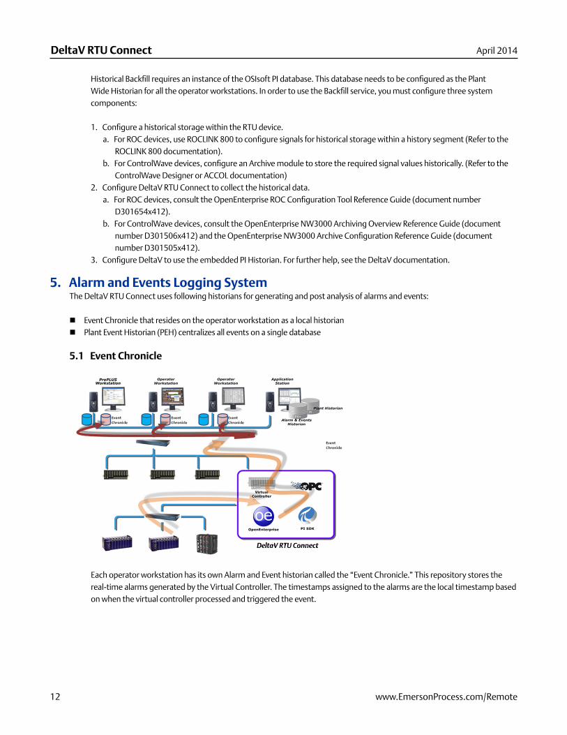
5.1 Event Chronicle
Each operator workstation has its own Alarm and Event historian called the “Event Chronicle.” This repository stores the real-time alarms generated by the Virtual Controller. The timestamps assigned to the alarms are the local timestamp based on when the virtual controller processed and triggered the event.
www.EmersonProcess.com/Remote 13
DeltaV RTU ConnectApril 2014
The DeltaV RTU Connects automatically passes the RTU alarm defi nitions and corresponding alarm limits and dead bands as OPC tags. The Virtual Controller actually generates DeltaV alarms (refer to the section Confi guration Output Files). The DeltaV RTU Connect Confi g Tool automatically generates the virtual controller code and alarm processing.
As such each DeltaV operator workstation is capable of displaying real-time alarms associated with fi eld RTUs.
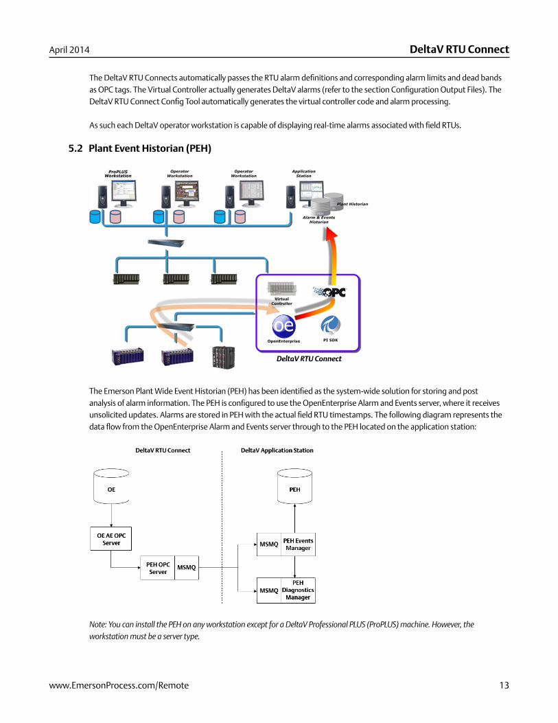
5.2 Plant Event Historian (PEH)
The Emerson Plant Wide Event Historian (PEH) has been identifi ed as the system-wide solution for storing and post analysis of alarm information. The PEH is confi gured to use the OpenEnterprise Alarm and Events server, where it receives unsolicited updates. Alarms are stored in PEH with the actual fi eld RTU timestamps. The following diagram represents the data fl ow from the OpenEnterprise Alarm and Events server through to the PEH located on the application station:
Note: You can install the PEH on any workstation except for a DeltaV Professional PLUS (ProPLUS) machine. However, the workstation must be a server type.
DeltaV RTU Connect
14 www.EmersonProcess.com/Remote
April 2014
The PEH uses a SQL server database as its data store. The PEH uses MSMQ to relay messages across to its interfacing components, allowing for buffering of messages during SCADA network downtime. The interfacing nodes include:
The PEH OPC server, the client application used to source events from the third-party alarm and events server (OpenEnterprise A & E server in this case).
The PEH events manager, used to manage the receipt ofdata from the PEH OPC server and insertion into the database. The PEH diagnostics server, used to receive and store diagnostics events from the PEH events manager and PEH OPC
server. These are then made available for viewing and troubleshooting, with DeltaV diagnostic tools.
6. The DeltaV RTU Connect Configuration ToolThe DeltaV RTU Connect Confi guration tool implements the following actions:
Selects OpenEnterprise tags (RTU data) which require export to DeltaV Automatically creates corresponding tags in DeltaV system Confi gures the communications pipe used within the OPC Mirror Confi gures historical integration (via the PI Historian) Confi gures alarm and events integration (via the PEH historian)
The Confi guration tool allows you to select the SCADA tags that you want to integrate into the DeltaV system. You can then export these tags to a control strategy fi le (.FHX), which then gets downloaded to a Virtual Controller module.
The DeltaV RTU Connect Confi guration tool also sends mapping information from the selected tags to the OPC Mirror, which enables the OpenEnterprise OPC server and the DeltaV OPC server to pass the data between them. The DeltaV OPC server then pushes the RTU data to the Virtual Controller making it accessible to the DeltaV system.
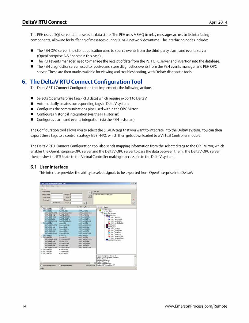
6.1 User InterfaceThis interface provides the ability to select signals to be exported from OpenEnterprise into DeltaV:
www.EmersonProcess.com/Remote 15
DeltaV RTU ConnectApril 2014
The user interface has the following components:
Signal DefinitionThe top left panel is used to search for signals based upon a set of fi lters, such as signal name, device name, description, etc. The panel also allows for the creation of rule sets. Rule sets are the criteria that specify search fi lters. Rule sets can be imported and exported and will be stored to an XML fi le. The button allows you to concatenate rules which display within the rule set viewer (as shown in the example). Rules can also be updated, using the update button to refl ect additional fi ltering criteria applied to existing rules. Searches can be based around the parameters entered into the text boxes or upon the rule sets defi ned.
Search SummaryThis is a list of signals which are available for export, based upon the search criteria defi ned within the rule set/search boxes. Gray colored rows indicate that a particular signal has previously been exported to DeltaV (determined by the deltavtagname attribute) and blue colored rows show asignal recently dragged into the DeltaV system view. This tool also associates corresponding alarms wherever possible. You can confi gure the alarms with signals (using Tools > Properties).
DeltaV System ExplorerThis provides a tree view which corresponds to the plant areas, modules and signals / alarms / dead bands. You can select signals from the search summary and drag and drop these to any relevant node within this view. This graphical representation will therefore defi ne the .FHX fi le produced. The panel below this tree view provides statistical information to the user, such as how many signals have been chosen for export, signal re-naming details, and the number of OPC Mirror links produced.
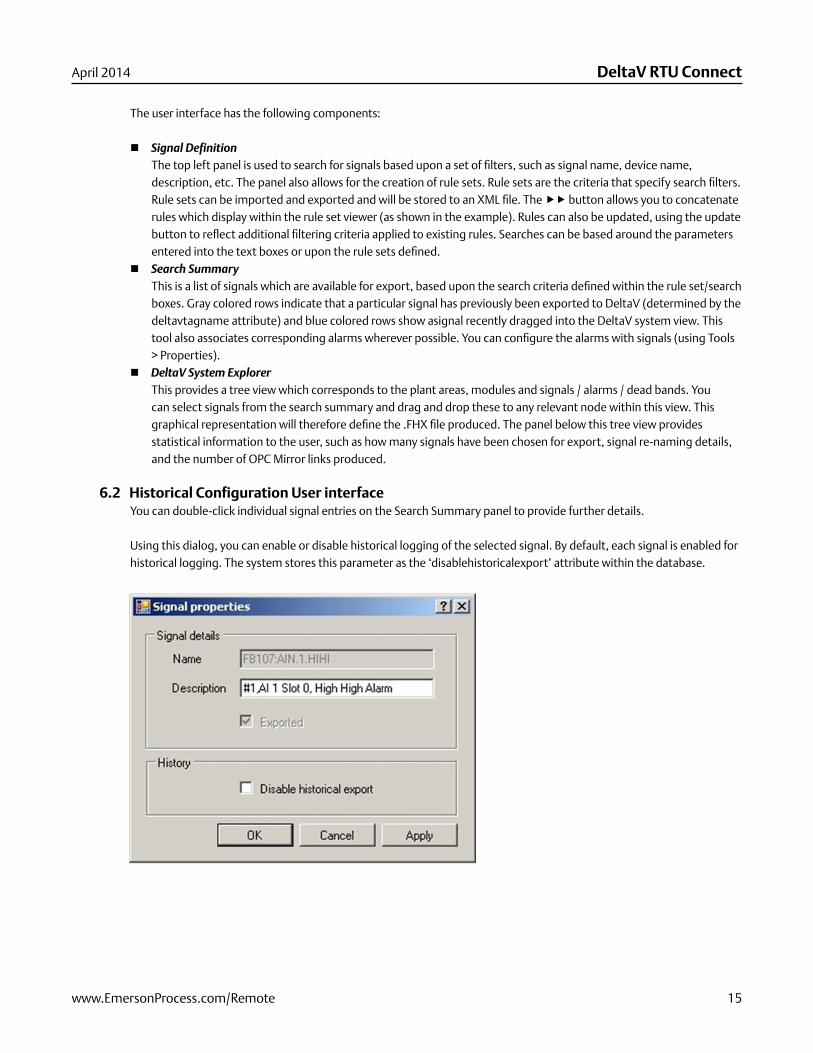
6.2 Historical Configuration User interfaceYou can double-click individual signal entries on the Search Summary panel to provide further details.
Using this dialog, you can enable or disable historical logging of the selected signal. By default, each signal is enabled for historical logging. The system stores this parameter as the ‘disablehistoricalexport’ attribute within the database.
DeltaV RTU Connect
16 www.EmersonProcess.com/Remote
April 2014
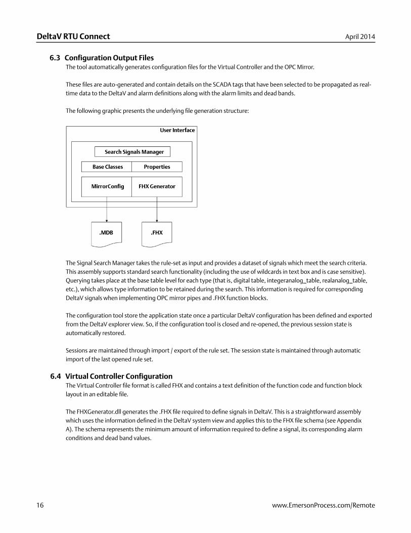
6.3 Configuration Output FilesThe tool automatically generates confi guration fi les for the Virtual Controller and the OPC Mirror.
These fi les are auto-generated and contain details on the SCADA tags that have been selected to be propagated as real-time data to the DeltaV and alarm defi nitions along with the alarm limits and dead bands.
The following graphic presents the underlying fi le generation structure:
The Signal Search Manager takes the rule-set as input and provides a dataset of signals which meet the search criteria. This assembly supports standard search functionality (including the use of wildcards in text box and is case sensitive). Querying takes place at the base table level for each type (that is, digital table, integeranalog_table, realanalog_table, etc.), which allows type information to be retained during the search. This information is required for corresponding DeltaV signals when implementing OPC mirror pipes and .FHX function blocks.
The confi guration tool store the application state once a particular DeltaV confi guration has been defi ned and exported from the DeltaV explorer view. So, if the confi guration tool is closed and re-opened, the previous session state is automatically restored.
Sessions are maintained through import / export of the rule set. The session state is maintained through automatic import of the last opened rule set.
6.4 Virtual Controller ConfigurationThe Virtual Controller fi le format is called FHX and contains a text defi nition of the function code and function block layout in an editable fi le.
The FHXGenerator.dll generates the .FHX fi le required to defi ne signals in DeltaV. This is a straightforward assembly which uses the information defi ned in the DeltaV system view and applies this to the FHX fi le schema (see Appendix A). The schema represents the minimum amount of information required to defi ne a signal, its corresponding alarm conditions and dead band values.
www.EmersonProcess.com/Remote 17
DeltaV RTU ConnectApril 2014
The FHXGenerator creates native and emulated alarm blocks. A native alarm block (or alternatively comparator block) is the term used to describe a DeltaV alarm function block. Each single alarm function block incurs a single Device Signal Tag (DST). The comparator block alternative has no DST licensing considerations. An emulated alarm block is a set of function blocks that simulates native alarm function block functionality. The emulated alarm block comprises a number of LIMIT, ADD, SUB, and NOT function blocks. Note that this compound set of blocks does not incur any DST costs. You can optionally select which type of alarm block to confi gure using the confi guration tool.
By default all signals are enabled for historical logging. However, you can disable this feature in the confi guration tool. After generating of the DeltaV .FHX fi le, you must manually import this into DeltaV.
We suggest that you fi rst import the .FHX fi le into the DeltaV Professional PLUS workstation and then assign each plant area to the appropriate Virtual Controller. You must then download the confi guration to make the signals available.
6.5 OPC Mirror ConfigurationThe confi guration tool automatically updates the OPC Mirror database with the current confi guration during export.
Note: A service restart is required before the OPC mirror can apply these new pipes. We suggest that you accomplish this within the service’s Microsoft management console.
The MirrorConfi guration.dll takes the set of chosen export signals as input and directly inserts these signals into the OPC Mirror confi guration database. This is achieved using standard .NET OLE DB queries and transactions into the database. All necessary information is inserted into the database in order to create an OPC Mirror pipe. An OPC mirror pipe is defi ned as a set of mappings between two OPC servers, enabling data transfer. The specifi ed details therefore include the machine names of both OPC servers and tag information.
6.6 Command Line UsageThis tool is available as a toolbox editor, and can be used on any OpenEnterprise workstation or server. When launched from OE ToolBox, the standard editor command line parameters is supported.
DeltaVConnect.exe –s%Database% -u%User% -p%Password% -nDeviceName
Where:Database is the data service of the database, e.g. “rtrdb1”User and Password are the credentials of the currently logged-on user.n is the name of a specifi c device.
Note: The n parameter provides a link into the ROC tools and the NW3000 confi guration tool.
DeltaV RTU Connect
18 www.EmersonProcess.com/Remote
April 2014
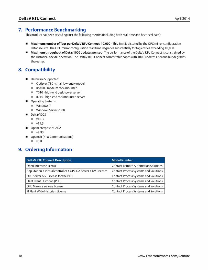
7. Performance BenchmarkingThis product has been tested against the following metrics (including both real-time and historical data):
Maximum number of Tags per DeltaV RTU Connect: 10,000 - This limit is dictated by the OPC mirror confi guration database size. The OPC mirror confi guration read time degrades substantially for tag entries exceeding 10,000.
Maximum throughput of Data: 1000 updates per sec - The performance of the DeltaV RTU Connect is constrained by the Historical backfi ll operation. The DeltaV RTU Connect comfortable copes with 1000 updates a second but degrades thereafter.
8. Compatibility
Hardware Supported:Optiplex 780 - small low-entry modelR5400 - medium rack-mountedT610 - high-end desk tower serverR710 - high-end rackimounted server
Operating SystemsWindows 7 Windows Server 2008
DeltaV DCS v10.3v11.3
OpenEnterprise SCADAv2.83
OpenBSI (RTU Communications)v5.8
9. Ordering Information
DeltaV RTU Connect Description Model Number
OpenEnterprise license Contact Remote Automation Solutions
App Station + Virtual controller + OPC DA Server + DV Licenses Contact Process Systems and Solutions
OPC Server A&E License for the PEH Contact Process Systems and Solutions
Plant Event Historian (PEH) Contact Process Systems and Solutions
OPC Mirror 2 servers license Contact Process Systems and Solutions
PI Plant Wide Historian License Contact Process Systems and Solutions
www.EmersonProcess.com/Remote 19
DeltaV RTU ConnectApril 2014
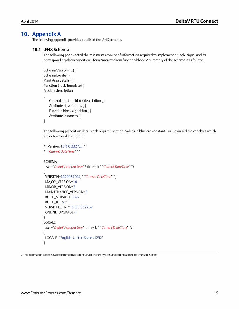
10. Appendix AThe following appendix provides details of the .FHX schema.
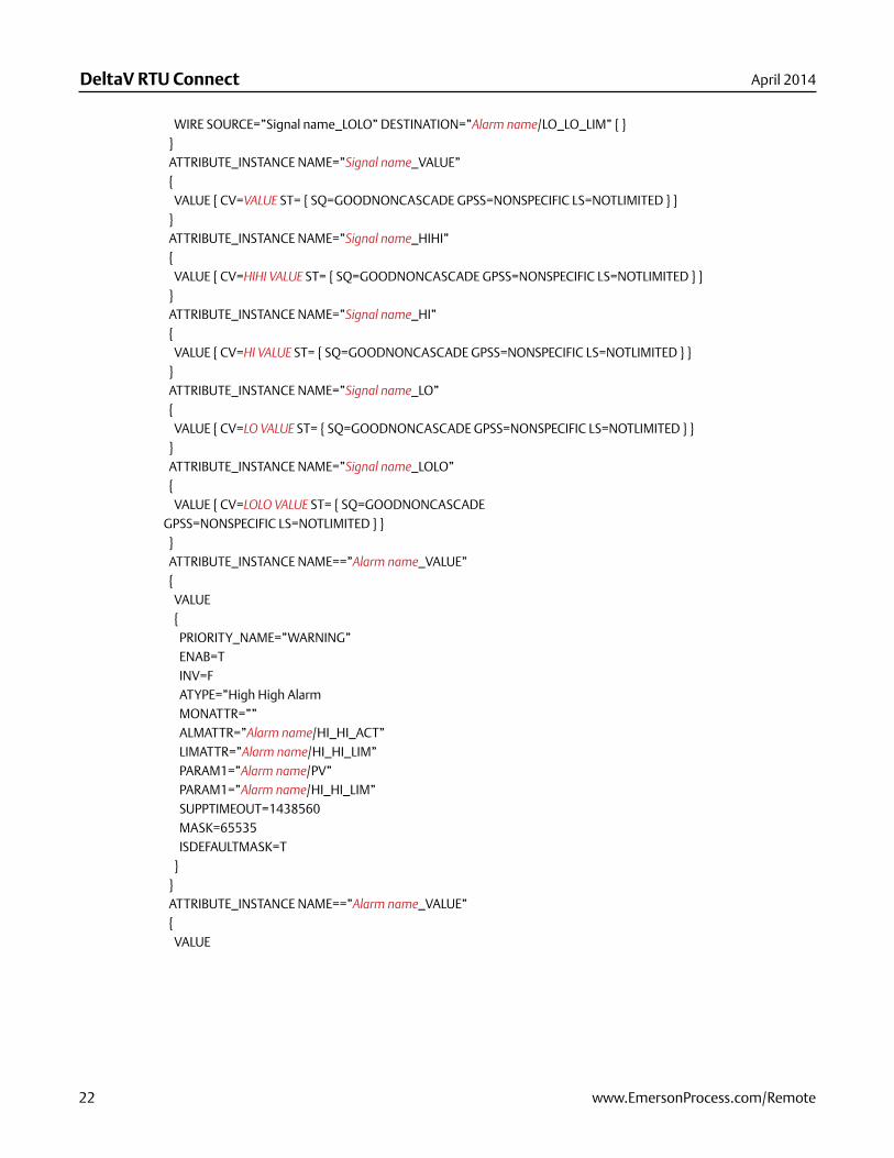
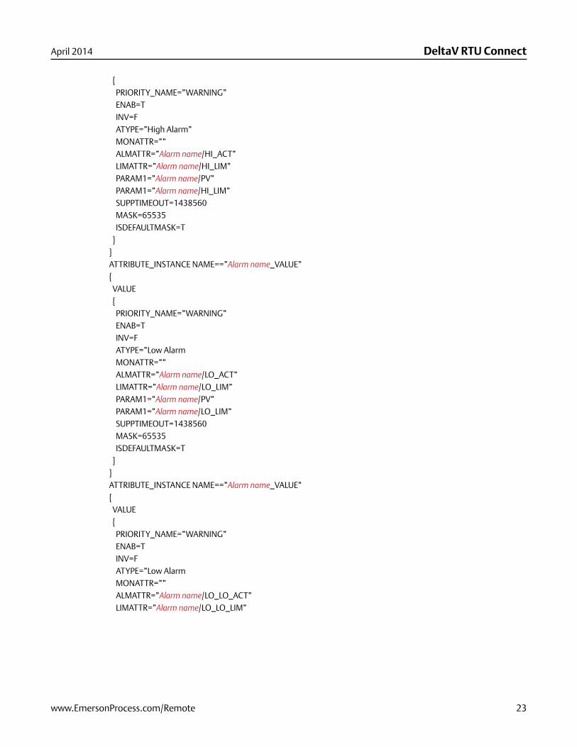
10.1 .FHX SchemaThe following pages detail the minimum amount of information required to implement a single signal and its corresponding alarm conditions, for a “native” alarm function block. A summary of the schema is as follows:
Schema Versioning { }Schema Locale { }Plant Area details { }Function Block Template { }Module description{ General function block description { } Attribute descriptions { } Function block algorithm { } Attribute instances { }}
The following presents in detail each required section. Values in blue are constants; values in red are variables which are determined at runtime.
/* Version: 10.3.0.3327.xr *//* “Current DateTime” */
SCHEMA user=”DeltaV Account User”2 time=1/* “Current DateTime” */{ VERSION=1229054204/* “Current DateTime” */ MAJOR_VERSION=10 MINOR_VERSION=3 MAINTENANCE_VERSION=0 BUILD_VERSION=3327 BUILD_ID=”xr” VERSION_STR=”10.3.0.3327.xr” ONLINE_UPGRADE=F}LOCALE user=”DeltaV Account User” time=1/* “Current DateTime” */{ LOCALE=”English_United States.1252”}
2 This information is made available through a custom C# .dll created by EEEC and commissioned by Emerson, Stirling.

DeltaV RTU Connect
20 www.EmersonProcess.com/Remote
April 2014
3 These are fi xed values, due to the limited space within Control Designer to display alarm blocks.
}PLANT_AREA NAME=”Plant Area” INDEX=0user=”DeltaV Account User” time=1/* “Current DateTime” */{ DESCRIPTION=”Plant area description”}FUNCTION_BLOCK_TEMPLATE NAME=”ALM” user=”DeltaV Account User” time=1/* “Current DateTime” */{ DESCRIPTION=”Alarm Detection”}MODULE TAG=”Tag group name” PLANT_AREA=”Plant Area” CATEGORY=”” user=”DeltaV Account User” time=1/* “Current DateTime” */{ DESCRIPTION=”Control Module” PERIOD=1 CONTROLLER=”Professional Plus Machine name” PRIMARY_CONTROL_DISPLAY=”” INSTRUMENT_AREA_DISPLAY=”MOD_FP” DETAIL_DISPLAY=”” TYPE=”” SUB_TYPE=”” ASSIGN_BLOCKS_TO_H1_CARD=F FUNCTION_BLOCK NAME=”ALM_Signal name” DEFINITION=”ALM” { DESCRIPTION=”Alarm Detection” RECTANGLE= { X=220 Y=50 H=56 W=140 }3 ADDITIONAL_CONNECTOR NAME=”HI_HI_LIM” TYPE=INPUT {ATTRIBUTE=”HI_HI_LIM” } ADDITIONAL_CONNECTOR NAME=”HI_LIM” TYPE=INPUT {ATTRIBUTE=”HI_LIM” } ADDITIONAL_CONNECTOR NAME=”LO_LIM” TYPE=INPUT {ATTRIBUTE=”LO_LIM” } ADDITIONAL_CONNECTOR NAME=”LO_LO_LIM” TYPE=INPUT {ATTRIBUTE=”LO_LO_LIM” } } ATTRIBUTE NAME=”Signal name_VALUE” TYPE=Parameter type { CONNECTION=INPUT RECTANGLE = { X=50 Y=70 H=20 W=110 } CATEGORY { CATEGORY=COMMON } } ATTRIBUTE NAME=”Signal name_HIHI” TYPE=Parameter type { CONNECTION=INPUT RECTANGLE = { X=50 Y=110 H=20 W=110 } CATEGORY { CATEGORY=COMMON } }
www.EmersonProcess.com/Remote 21
DeltaV RTU ConnectApril 2014
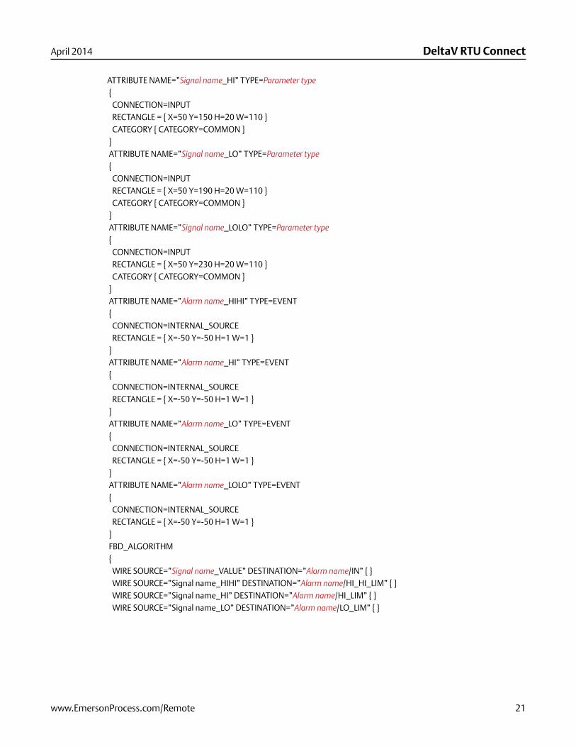
ATTRIBUTE NAME=”Signal name_HI” TYPE=Parameter type { CONNECTION=INPUT RECTANGLE = { X=50 Y=150 H=20 W=110 } CATEGORY { CATEGORY=COMMON } } ATTRIBUTE NAME=”Signal name_LO” TYPE=Parameter type { CONNECTION=INPUT RECTANGLE = { X=50 Y=190 H=20 W=110 } CATEGORY { CATEGORY=COMMON } } ATTRIBUTE NAME=”Signal name_LOLO” TYPE=Parameter type { CONNECTION=INPUT RECTANGLE = { X=50 Y=230 H=20 W=110 } CATEGORY { CATEGORY=COMMON } } ATTRIBUTE NAME=”Alarm name_HIHI” TYPE=EVENT { CONNECTION=INTERNAL_SOURCE RECTANGLE = { X=-50 Y=-50 H=1 W=1 } } ATTRIBUTE NAME=”Alarm name_HI” TYPE=EVENT { CONNECTION=INTERNAL_SOURCE RECTANGLE = { X=-50 Y=-50 H=1 W=1 } } ATTRIBUTE NAME=”Alarm name_LO” TYPE=EVENT { CONNECTION=INTERNAL_SOURCE RECTANGLE = { X=-50 Y=-50 H=1 W=1 } } ATTRIBUTE NAME=”Alarm name_LOLO” TYPE=EVENT { CONNECTION=INTERNAL_SOURCE RECTANGLE = { X=-50 Y=-50 H=1 W=1 } } FBD_ALGORITHM { WIRE SOURCE=”Signal name_VALUE” DESTINATION=”Alarm name/IN” { } WIRE SOURCE=”Signal name_HIHI” DESTINATION=”Alarm name/HI_HI_LIM” { } WIRE SOURCE=”Signal name_HI” DESTINATION=”Alarm name/HI_LIM” { } WIRE SOURCE=”Signal name_LO” DESTINATION=”Alarm name/LO_LIM” { }
DeltaV RTU Connect
22 www.EmersonProcess.com/Remote
April 2014
WIRE SOURCE=”Signal name_LOLO” DESTINATION=”Alarm name/LO_LO_LIM” { } } ATTRIBUTE_INSTANCE NAME=”Signal name_VALUE” { VALUE { CV=VALUE ST= { SQ=GOODNONCASCADE GPSS=NONSPECIFIC LS=NOTLIMITED } } } ATTRIBUTE_INSTANCE NAME=”Signal name_HIHI” { VALUE { CV=HIHI VALUE ST= { SQ=GOODNONCASCADE GPSS=NONSPECIFIC LS=NOTLIMITED } } } ATTRIBUTE_INSTANCE NAME=”Signal name_HI” { VALUE { CV=HI VALUE ST= { SQ=GOODNONCASCADE GPSS=NONSPECIFIC LS=NOTLIMITED } } } ATTRIBUTE_INSTANCE NAME=”Signal name_LO” { VALUE { CV=LO VALUE ST= { SQ=GOODNONCASCADE GPSS=NONSPECIFIC LS=NOTLIMITED } } } ATTRIBUTE_INSTANCE NAME=”Signal name_LOLO” { VALUE { CV=LOLO VALUE ST= { SQ=GOODNONCASCADEGPSS=NONSPECIFIC LS=NOTLIMITED } } } ATTRIBUTE_INSTANCE NAME==”Alarm name_VALUE” { VALUE { PRIORITY_NAME=”WARNING” ENAB=T INV=F ATYPE=”High High Alarm MONATTR=”” ALMATTR=”Alarm name/HI_HI_ACT” LIMATTR=”Alarm name/HI_HI_LIM” PARAM1=”Alarm name/PV” PARAM1=”Alarm name/HI_HI_LIM” SUPPTIMEOUT=1438560 MASK=65535 ISDEFAULTMASK=T } } ATTRIBUTE_INSTANCE NAME==”Alarm name_VALUE” { VALUE
www.EmersonProcess.com/Remote 23
DeltaV RTU ConnectApril 2014
{ PRIORITY_NAME=”WARNING” ENAB=T INV=F ATYPE=”High Alarm” MONATTR=”” ALMATTR=”Alarm name/HI_ACT” LIMATTR=”Alarm name/HI_LIM” PARAM1=”Alarm name/PV” PARAM1=”Alarm name/HI_LIM” SUPPTIMEOUT=1438560 MASK=65535 ISDEFAULTMASK=T } } ATTRIBUTE_INSTANCE NAME==”Alarm name_VALUE” { VALUE { PRIORITY_NAME=”WARNING” ENAB=T INV=F ATYPE=”Low Alarm MONATTR=”” ALMATTR=”Alarm name/LO_ACT” LIMATTR=”Alarm name/LO_LIM” PARAM1=”Alarm name/PV” PARAM1=”Alarm name/LO_LIM” SUPPTIMEOUT=1438560 MASK=65535 ISDEFAULTMASK=T } } ATTRIBUTE_INSTANCE NAME==”Alarm name_VALUE” { VALUE { PRIORITY_NAME=”WARNING” ENAB=T INV=F ATYPE=”Low Alarm MONATTR=”” ALMATTR=”Alarm name/LO_LO_ACT” LIMATTR=”Alarm name/LO_LO_LIM”

© 2012-2014 Remote Automation Solutions, a business unit of Emerson Process Management. All rights reserved.
Emerson Process Management Ltd, Remote Automation Solutions (UK), is a wholly owned subsidiary of Emerson Electric Co. doing business as Remote Automation Solutions, a business unit of Emerson Process Management. FloBoss, ROCLINK, ControlWave, Helicoid, and OpenEnterprise are trademarks of Remote Automation Solutions. AMS, PlantWeb, and the PlantWeb logo are marks of Emerson Electric Co. The Emerson logo is a trademark and service mark of the Emerson Electric Co. All other marks are property of their respective owners.
The contents of this publication are presented for informational purposes only. While every effort has been made to ensure informational accuracy, they are not to be construed as warranties or guarantees, express or implied, regarding the products or services described herein or their use or applicability. Remote Automation Solutions reserves the right to modify or improve the designs or specifications of such products at any time without notice. All sales are governed by Remote Automation Solutions’ terms and conditions which are available upon request. Remote Automation Solutions does not assume responsibility for the selection, use or maintenance of any product. Responsibility for proper selection, use and maintenance of any Remote Automation Solutions product remains solely with the purchaser and end-user.
Global HeadquartersEmerson Process ManagementRemote Automation Solutions6005 Rogerdale RoadHouston, TX, USA 77072T +1 281 879 2699 F +1 281 988 4445
www.EmersonProcess.com/Remote
EuropeEmerson Process ManagementRemote Automation SolutionsUnit 8, Waterfront Business ParkDudley Road, Brierley HillDudley, UK DY5 1LXT +44 1384 487200 F +44 1384 487258
North America and Latin AmericaEmerson Process ManagementRemote Automation Solutions6005 Rogerdale RoadHouston, TX, USA 77072T +1 281 879 2699 F +1 281 988 4445
Middle East and AfricaEmerson Process ManagementRemote Automation SolutionsEmerson FZEPO Box 17033Jebel Ali Free Zone - South 2Dubai, UAET +971 4 8118100 F +1 281 988 4445
Asia PacificEmerson Process ManagementRemote Automation Solutions1 Pandan CrescentSingapore 128461T +65 6777 8211F +65 6777 0947
White PaperApril 2014
DeltaV RTU ConnectD351498X412
PARAM1=”Alarm name/PV” PARAM1=”Alarm name/LO_LO_LIM” SUPPTIMEOUT=1438560 MASK=65535 ISDEFAULTMASK=T } } ATTRIBUTE_INSTANCE NAME=”Alarm name/HI_HI_LIM” { VALUE { CV= HI HI VALUE } } ATTRIBUTE_INSTANCE NAME=”Alarm name/HI_LIM” { VALUE { CV= HI VALUE } } ATTRIBUTE_INSTANCE NAME=”Alarm name/LO_LIM” { VALUE { CV= LO VALUE } } ATTRIBUTE_INSTANCE NAME=”Alarm name/LO_LO_LIM” { VALUE { CV= LO LO VALUE }