Toward an interactive article: integrating journals and biological
INTEGRATING INTERACTIVE DESIGN AND SIMULATION FOR MASSCUSTOMIZED 3D-PRINTED OBJECTS – A CUP HOLDER EXAMPLE
C. Altenhofen*†, F. Loosmann*†, J. S. Mueller-Roemer *†, T. Grasser*†, T. H. Luu*†, and A.Stork*†
*Fraunhofer Institute for Computer Graphics Research IGD, 64283 Darmstadt, Germany†Technische Universität Darmstadt, 64283 Darmstadt, Germany
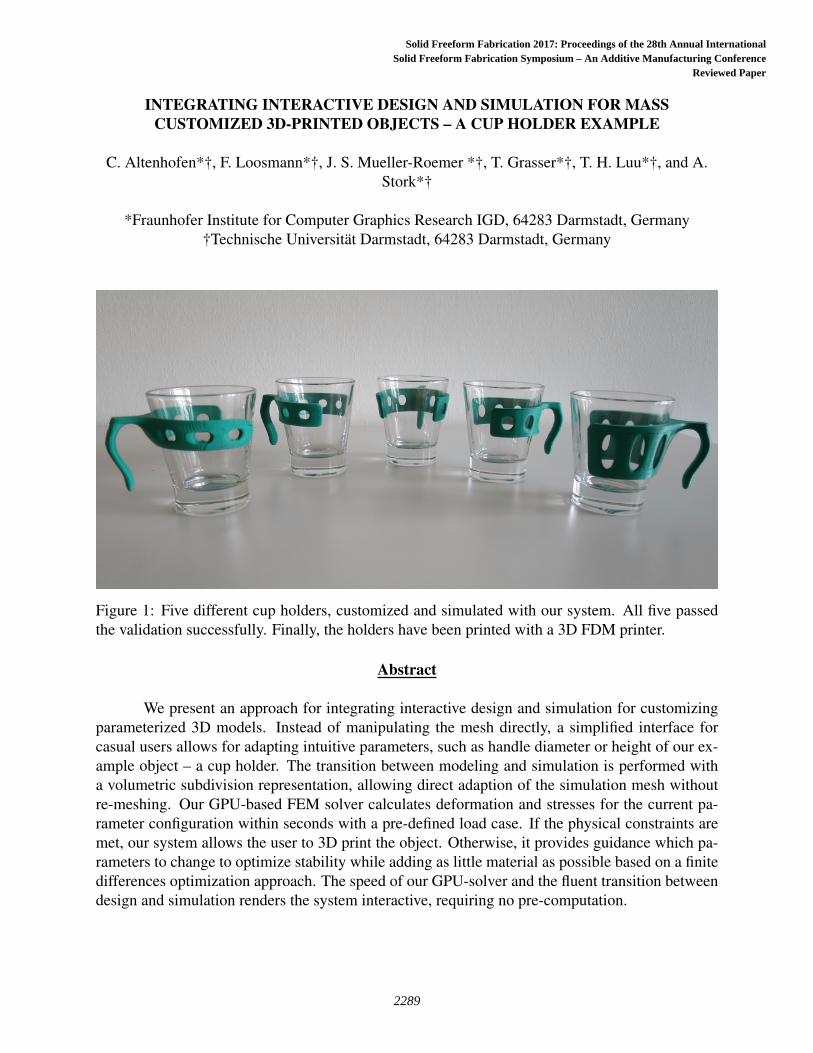
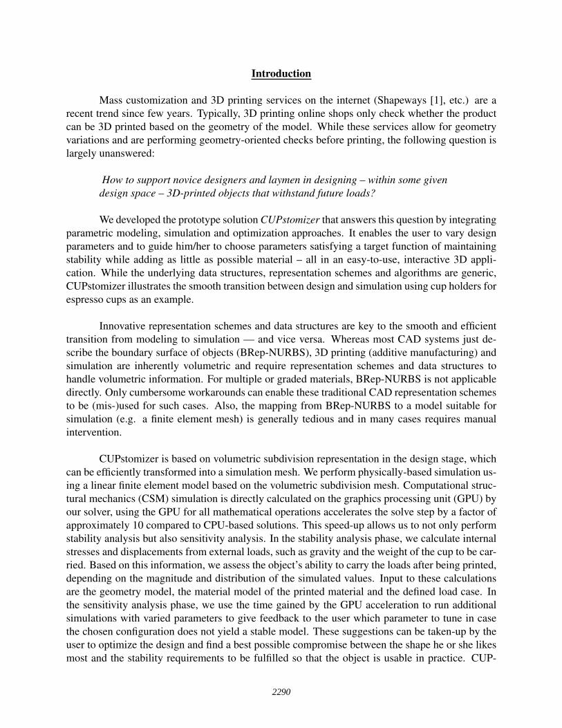
Figure 1: Five different cup holders, customized and simulated with our system. All five passedthe validation successfully. Finally, the holders have been printed with a 3D FDM printer.
Abstract
We present an approach for integrating interactive design and simulation for customizingparameterized 3D models. Instead of manipulating the mesh directly, a simplified interface forcasual users allows for adapting intuitive parameters, such as handle diameter or height of our ex-ample object – a cup holder. The transition between modeling and simulation is performed witha volumetric subdivision representation, allowing direct adaption of the simulation mesh withoutre-meshing. Our GPU-based FEM solver calculates deformation and stresses for the current pa-rameter configuration within seconds with a pre-defined load case. If the physical constraints aremet, our system allows the user to 3D print the object. Otherwise, it provides guidance which pa-rameters to change to optimize stability while adding as little material as possible based on a finitedifferences optimization approach. The speed of our GPU-solver and the fluent transition betweendesign and simulation renders the system interactive, requiring no pre-computation.
2289
Solid Freeform Fabrication 2017: Proceedings of the 28th Annual InternationalSolid Freeform Fabrication Symposium – An Additive Manufacturing Conference
Reviewed Paper
Introduction
Mass customization and 3D printing services on the internet (Shapeways [1], etc.) are arecent trend since few years. Typically, 3D printing online shops only check whether the productcan be 3D printed based on the geometry of the model. While these services allow for geometryvariations and are performing geometry-oriented checks before printing, the following question islargely unanswered:
How to support novice designers and laymen in designing – within some givendesign space – 3D-printed objects that withstand future loads?
We developed the prototype solution CUPstomizer that answers this question by integratingparametric modeling, simulation and optimization approaches. It enables the user to vary designparameters and to guide him/her to choose parameters satisfying a target function of maintainingstability while adding as little as possible material – all in an easy-to-use, interactive 3D appli-cation. While the underlying data structures, representation schemes and algorithms are generic,CUPstomizer illustrates the smooth transition between design and simulation using cup holders forespresso cups as an example.
Innovative representation schemes and data structures are key to the smooth and efficienttransition from modeling to simulation — and vice versa. Whereas most CAD systems just de-scribe the boundary surface of objects (BRep-NURBS), 3D printing (additive manufacturing) andsimulation are inherently volumetric and require representation schemes and data structures tohandle volumetric information. For multiple or graded materials, BRep-NURBS is not applicabledirectly. Only cumbersome workarounds can enable these traditional CAD representation schemesto be (mis-)used for such cases. Also, the mapping from BRep-NURBS to a model suitable forsimulation (e.g. a finite element mesh) is generally tedious and in many cases requires manualintervention.
CUPstomizer is based on volumetric subdivision representation in the design stage, whichcan be efficiently transformed into a simulation mesh. We perform physically-based simulation us-ing a linear finite element model based on the volumetric subdivision mesh. Computational struc-tural mechanics (CSM) simulation is directly calculated on the graphics processing unit (GPU) byour solver, using the GPU for all mathematical operations accelerates the solve step by a factor ofapproximately 10 compared to CPU-based solutions. This speed-up allows us to not only performstability analysis but also sensitivity analysis. In the stability analysis phase, we calculate internalstresses and displacements from external loads, such as gravity and the weight of the cup to be car-ried. Based on this information, we assess the object’s ability to carry the loads after being printed,depending on the magnitude and distribution of the simulated values. Input to these calculationsare the geometry model, the material model of the printed material and the defined load case. Inthe sensitivity analysis phase, we use the time gained by the GPU acceleration to run additionalsimulations with varied parameters to give feedback to the user which parameter to tune in casethe chosen configuration does not yield a stable model. These suggestions can be taken-up by theuser to optimize the design and find a best possible compromise between the shape he or she likesmost and the stability requirements to be fulfilled so that the object is usable in practice. CUP-
2290
Stomizer unlocks the 3D printing option for the end user only if the designed object complies tothe requirements. Figure 1 shows five 3D-printed cup holders, customized with our application.
These innovative aspects of CUPstomizer: parameterized volumetric modeling, efficientFEM simulation including suggestions for optimization and an intuitive user interface for casualusers are described and discussed in detail in the sections “Modeling”, “Simulation”, and “UserInterface” respectively.
Related Work
Geometric Representations: In the CAD domain, continuous representations such as B-splines or NURBS patches are widespread. They allow for a definition of smooth surfaces witha relatively low number of degrees of freedom, the so-called control points. Multiple patches areoften combined via trimming, creating complex transitions between them. In computer graphicsand animation, subdivision surfaces have been used for many years to create smooth 3D models.Similar to NURBS and B-splines, they are also based on control points, but rely on an iterativerefinement process instead of a direct mathematical description. In 1978, Doo and Sabin [2] aswell as Catmull and Clark [3] independently presented different subdivision schemes for smoothsurfaces. Many more followed over the years. While some subdivision schemes require a con-trol mesh with a certain topology, e.g. purely triangular meshes for the scheme presented byLoop [4], others can operate on control meshed with arbitrary topology (such as the ones by Dooand Sabin [2] and Catmull and Clark [3]).
However, subdivision surfaces as well as B-splines and NURBS patches only describe sur-face models. Even implicit volumetric descriptions such as closed and manifold surfaces meshesor BReps do not contain volumetric information per se. Similar to subdivision surfaces, volumet-ric subdivision schemes exist. In 1999, Joy and MacCracken [5] presented a volumetric extensionto the Catmull-Clark subdivision scheme. In addition to faces, edges and vertices, volumetricschemes also introduce cells that are subdivided iteratively, resulting in a fully volumetric meshwith arbitrary resolution. Since Catmull-Clark solids can operate on arbitrary volumetric controlmeshes, but create mainly hexahedral meshes during subdivision, other methods were presentedthat operate on and create tetrahedral meshes (e.g. by Chang et al. [6] and Schaefer [7]). Thelatter are especially useful when aiming for finite element simulations as presented in the nextsubsection. As for those simulations, discrete volumetric meshes (in most cases purely tetrahedralmeshes) are required, volumetric subdivision algorithms provide good control over the granularityand mesh resolution. They are often used for global or local mesh refinement and re-meshing aspresented by e.g. Burkhart et al. [8]. Altenhofen et al. [9] recently presented an approach thatuses Catmull-Clark solids for volumetric 3D modeling as well as fast and consistent tetrahedralmeshing for finite element simulations.
Although, subdivision algorithms have been mainly developed for geometric use cases,some approaches exist to directly use the subdivision mesh for simulation. Wawrzinek et al. pre-sented a method for subdivision surfaces [10] while Burkhart et al. show an approach for thevolumetric case [11].
2291
Finite Element Method FEM: The Finite Element Method (FEM) as presented byZienkiewicz et al. in 1997 [12] is widely used for physical and physically-based simulation, es-pecially in the domain of structural mechanics. FEM was first developed for and used in theengineering domain. Later, adapted methods were invented for computer graphics and animation,e.g. by Müller et al. in 2002 [13] and Nealen et al. in 2006 [14]. Typically, finite element simula-tions require the solving of a large sparse linear system of equations. Classical CPU-based solverswere studied well and have been the state of the art for many years. Weber et al. [15, 16] presenteddata structures and algorithms, developed for GPU architectures, for solving large sparse linearsystems of equations. By using the computational potential of modern GPUs, huge improvementsto the performance can be achieved.
The core idea of the FEM is to divide the simulation domain into discrete parts (the so-called finite elements) and discretize the physical equations locally for every element. In a secondstep, an implicit equation is solved to calculate the global result. To create a finite element meshfrom a CAD model, the continuous surface representation has to be transformed into a discrete andfully volumetric model (the so-called meshing process). This is a complex and error-prone task,especially for non-watertight surface models. When frequently changing the design and re-runningthe simulation, the costs for meshing multiply with the number of design changes. Representingthe design model with one of the volumetric subdivision approaches described in the previous sub-section, proves to be much more suitable for simulating changing designs as shown by Altenhofenet al. [9].
Customization and Parametric Design: Custom adjustment of products is getting moreand more popular, especially driven by the rapid development of 3D printers promising a costeffective fabrication of such products. The advantage compared to traditional mass fabrication isapparent, since personalized products provide more appealing aesthetics (e.g., jewelry, householdobjects), better functional adaptability (e.g., prostheses) or more comfort (e.g., shoes).
Already a few web-based applications tackle the challenge to provide the possibility tothe user to model his or her individual product. Examples are Shapeways [1] or Nervous Sys-tem [17]. However, their customization possibilities are often restricted to very simple changes.Compared to that, shape editing and assembly-based methods from the field of computer graph-ics like iWire by Gal et al. [18] or the work by Bokelo et al. [19] provide broad and fast shapeediting methods yielding visually pleasing and intuitive results. However, they do not guarantee,that the customized objects are valid for fabrication, which leads to an iterative trial and error pro-cess between modeling and time-consuming validation. In CAD applications like AutoCAD[20]or SolidWorks [21] it is possible to put constraints on parameters, which could restrict the userto only generate valid models. However, to detect functional failures in a model, expert knowl-edge is still needed, which makes it difficult to determine the right parameters for a model. Thismakes the approach non-suitable for novice users. One example of combining geometric designand physical functionality is the work done by Umetani et al. [22]. They provide a real-time in-tegrated analysis and design system, which guides the user in his design process. However theirdesign domain is strictly limited to nail-jointed, plank-based furniture modeling, making it hard toutilize their system for more general applications. Shugrina et al. [23] presented a more generaltechnique to maintain the validity and ensure that a parametric design customized by a non-expert
2292
user can be fabricated. For that they introduce their own representation format Fab Form as anabstraction for representing customizable, manufacturable digital objects. However, it requires atime-consuming pre-processing step to sample the design space to determine valid regions wherethe user can navigate in and to cache geometry for fast look up. A similar precomputation regard-ing geometry sampling and caching accounts for the approach by Schulz et al. [24] that allowsinteractive exploration and optimization of parametric CAD data.
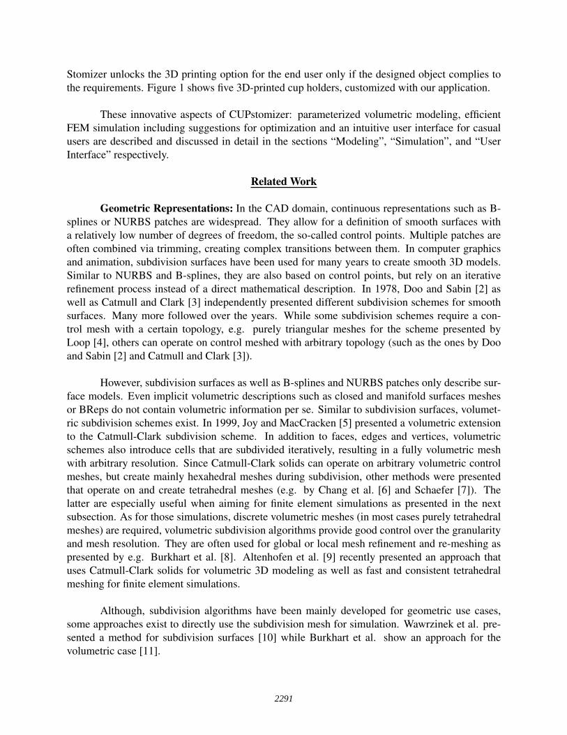
(a) The control mesh of the model. (b) Cup holder model attached tothe cup.
(c) 3D-printed cup holder.
Figure 2: The basic cup holder model. The holder is defined by a coarse control mesh shown as ablack grid and white vertices and the subdivided limit surface describing the actual model in lightbrown. This model can then be printed in 3D.
Modeling
Modeling with Subdivision Volumes: Common tools for polygonal modeling used in de-sign and computer animation, like SolidWorks [21], Rhino [25] or Maya [26], only support surfacemodeling. Although closed surface meshes implicitly describe a volumetric object, they are notconsidered as volumetric meshes. In addition to vertices, edges and faces, a volumetric mesh con-sists of cells and has inner faces to separate these cells. A closed surface mesh could however beconsidered as a volumetric mesh consisting of just one polyhedral cell.
In this work we, utilize a volumetric subdivision representation to model our objects.Throughout the whole modeling process, we keep the volumetric mesh that can later on be used forstability analysis simulation. To create complex models we use a block-based modeling scheme,which allows to create a variety of different objects and designs. In order to keep the number ofdegrees of freedom low for modeling, the coarse control mesh is used to define the 3D object anda subdivision algorithm is applied to create the actual model seen in Figure 2a. This gives highcontrol over the shape of the object allowing for intuitive modeling while at the same time createsvisually appealing surfaces. To carve out details it is possible to define sharp features and creaseedges. To obtain more details on the topic we recommend the work by Altenhofen et al. [9].
A basic model of our example object, a cup holder, is presented to the user as a startingpoint. The main shape is a C-shaped ring with a customary handle on the opposite side of the
2293

opening and round holes along the outside of the ring. The holder is designed to match the outersurface of the cup to provide secure positioning. Figure 2 shows the cup holder model. Of course,our application is not restricted to this model – it can be exchanged to represent other use caseswith different load cases, as e.g. a coat hook.
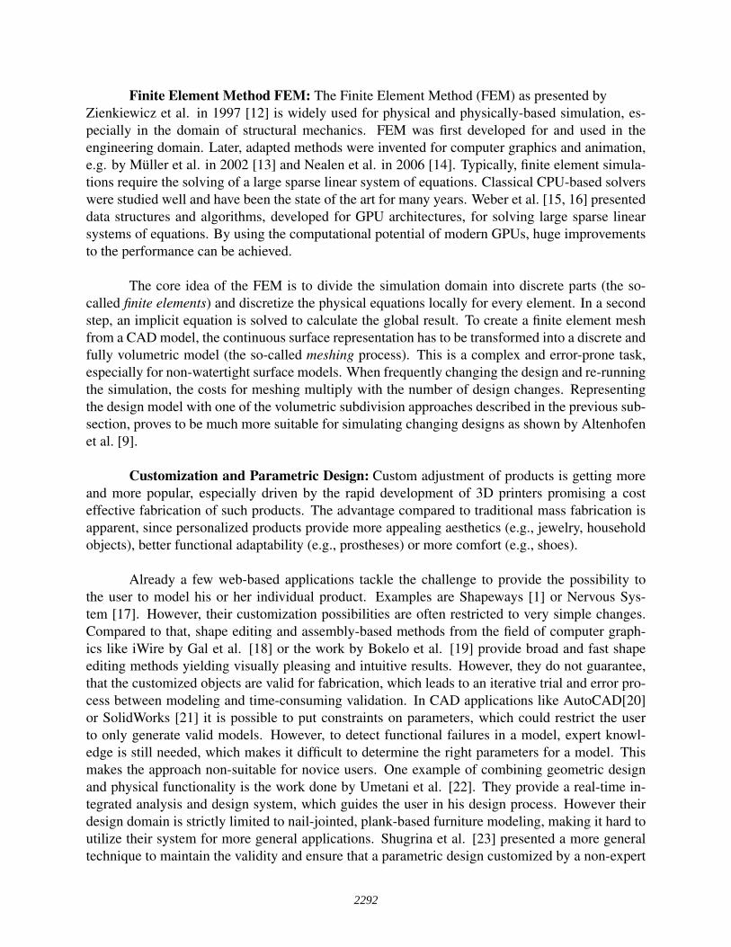
(a) The base model. (b) The parameter cup height is in-creased.
(c) The parameter middle radius isreduced.
Figure 3: Visualization of the effects of different parameter settings on our cup holder model. Thebase model is stretched by increasing the height and thinned by reducing the radius of the middlepart.
Model parametrization: Constrained parametric design is one of the most common cus-tomizable object representations. It allows capturing the design intent using features and con-straints, enabling users to easily perform changes. For example, organizations often turn to para-metric modeling when making families of products that include slight variations on a core design.
As previously described, the input to our application is a modeled volumetric control meshalong with a subset of parameters visible to end users. Parameters are defined by the designer forevery object in advance. This guaranties that all constraints are realistic, for example no invalidvalues (e.g., negative radius) can be assigned to parameters. Also 3D-printability should be consid-ered so that the result is among others a watertight mesh with minimum feature thickness above athreshold. Watertightness is especially covered by the nature of our modeling scheme with subdi-vision volumes since our modeling operations always preserve a closed volume mesh. Exceptionsmay arise if the model exhibits self-intersections, which the designer has to prevent.
For manipulating the geometry, parameters are mapped to constrained modeling operations.Those modeling operations can be arbitrarily complex geometry processing operations so that theunderlying parametric model can have a few orders of magnitude more degrees of freedom thanjust the few ones exposed to the user.
One parameter can consist of multiple parametric operations, which are defined as con-strained operations with a type, a range and a default value. These constrained operations arespecified on the vertices of the control mesh. This direct influence of the parameters on the controlpoints enables us to achieve an interactive geometry generation rate without geometry caching. Aset of vertices can be grouped into a constraint group, which is influenced by a constraint. How-
2294
ever, in the design phase they should be grouped in such a way that meaningful parameters arerealized, like e.g. the radius of the upper rim of the cup holder. An example of different modelingoperations is shown in Figure 3. The type of a constrained operation is defined by a symmetryreference object, such as a point or a plane, and a geometric operation, e.g. translation or rota-tion. The combination of the volumetric subdivision model with parametric extensions generateour parametric design model. Additionally, we provide a human readable text-based parameter fileto be able to store and load parameter settings. This allows importing previously modeled settingsinto different customizing applications.
Simulation
In order to evaluate the validity of a model by its physical properties, we perform a finiteelement simulation in our framework. While it is possible to evaluate multiple properties simul-taneously, it can be sufficient to evaluate only the most critical ones for a given scenario. For theexample of our c-shaped cup holder, the critical physical properties are not the resulting stressesbut the maximum displacement magnitude. In other words, the cup holder will more likely bendand release the cup than it will break. We defined a static load case, similar to the real life loadcase, induced by the gravitational forces of the filled cup and the forces applied by the humanhand to the handle. We used the material parameters of polylactic acid (PLA), which is a commonmaterial for 3D printing applications. While this was sufficient in our scenario, we designed thesimulation framework to allow for fast changes in the material parameters as well as the load cases.The simulation itself was performed on a tetrahedral mesh with linear finite elements and a linearstress model.
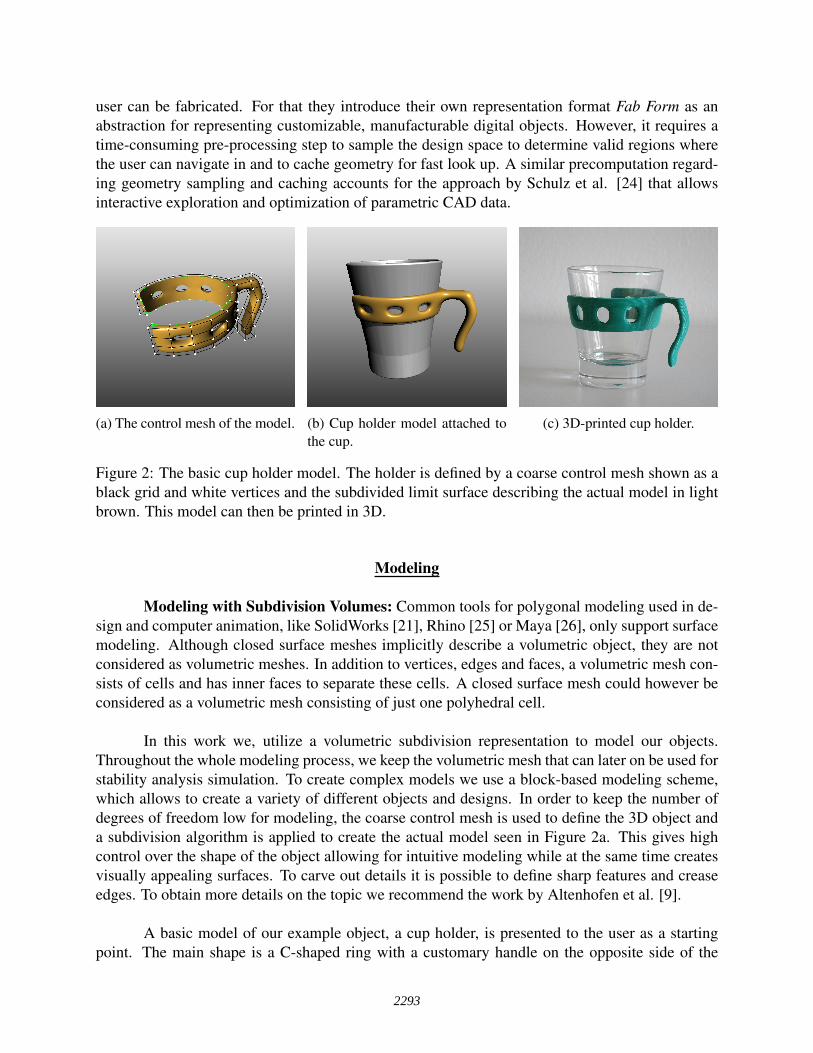
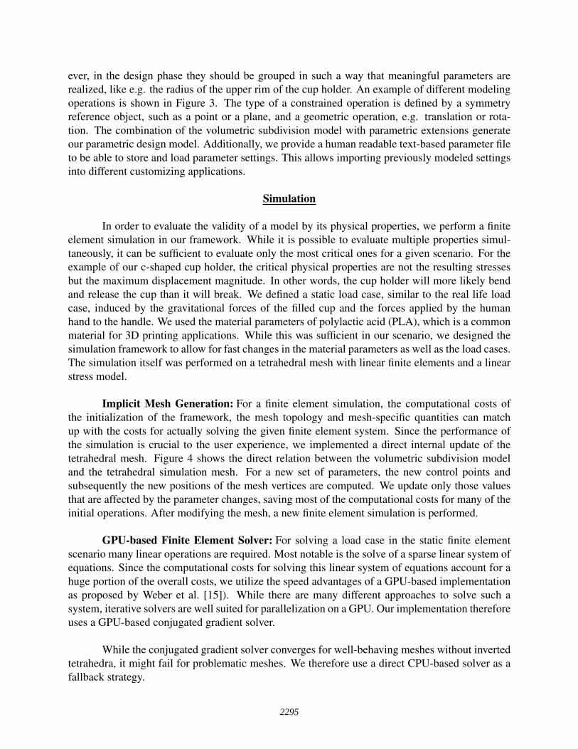
Implicit Mesh Generation: For a finite element simulation, the computational costs ofthe initialization of the framework, the mesh topology and mesh-specific quantities can matchup with the costs for actually solving the given finite element system. Since the performance ofthe simulation is crucial to the user experience, we implemented a direct internal update of thetetrahedral mesh. Figure 4 shows the direct relation between the volumetric subdivision modeland the tetrahedral simulation mesh. For a new set of parameters, the new control points andsubsequently the new positions of the mesh vertices are computed. We update only those valuesthat are affected by the parameter changes, saving most of the computational costs for many of theinitial operations. After modifying the mesh, a new finite element simulation is performed.
GPU-based Finite Element Solver: For solving a load case in the static finite elementscenario many linear operations are required. Most notable is the solve of a sparse linear system ofequations. Since the computational costs for solving this linear system of equations account for ahuge portion of the overall costs, we utilize the speed advantages of a GPU-based implementationas proposed by Weber et al. [15]). While there are many different approaches to solve such asystem, iterative solvers are well suited for parallelization on a GPU. Our implementation thereforeuses a GPU-based conjugated gradient solver.
While the conjugated gradient solver converges for well-behaving meshes without invertedtetrahedra, it might fail for problematic meshes. We therefore use a direct CPU-based solver as afallback strategy.
2295
(a) Smooth limit representation of the cupholder model.
(b) Tetrahedral mesh generated from (a).
Figure 4: Tetrahedral mesh generation from a subdivision model.
Suggestions for the user: In order to provide hints to a user on which parameter he or sheshould modify, we need to specify which value should be optimized. Stability is the most obviouscriteria. Since certain parameters always have a bigger impact on stability than others, we decidedto incorporate the volume of the model and set the target function to
f (p) =d(p)
vol(p)(1)
where d(p) is the maximum displacement and vol(p) is the volume of the mesh for a given set ofparameters p.
In order to provide hints on the impact of the different parameters, we determine the partialderivatives of the different parameters to the target function f . We chose to use one-sided finitedifferences
∆i f (p) = f (p+hi)− f (p) (2)
instead of central finite differences, since f (x) has to be computed only once for all parameterscombined. Here, hi = ε ∗ ei is a appropriate small delta to the i-th parameter, while ei is the i-thstandard basis vector.
Evaluating all partial derivatives and the simulation results themselves requires ||p||+ 1simulations, where ||p|| is the number of parameters.
User Interface
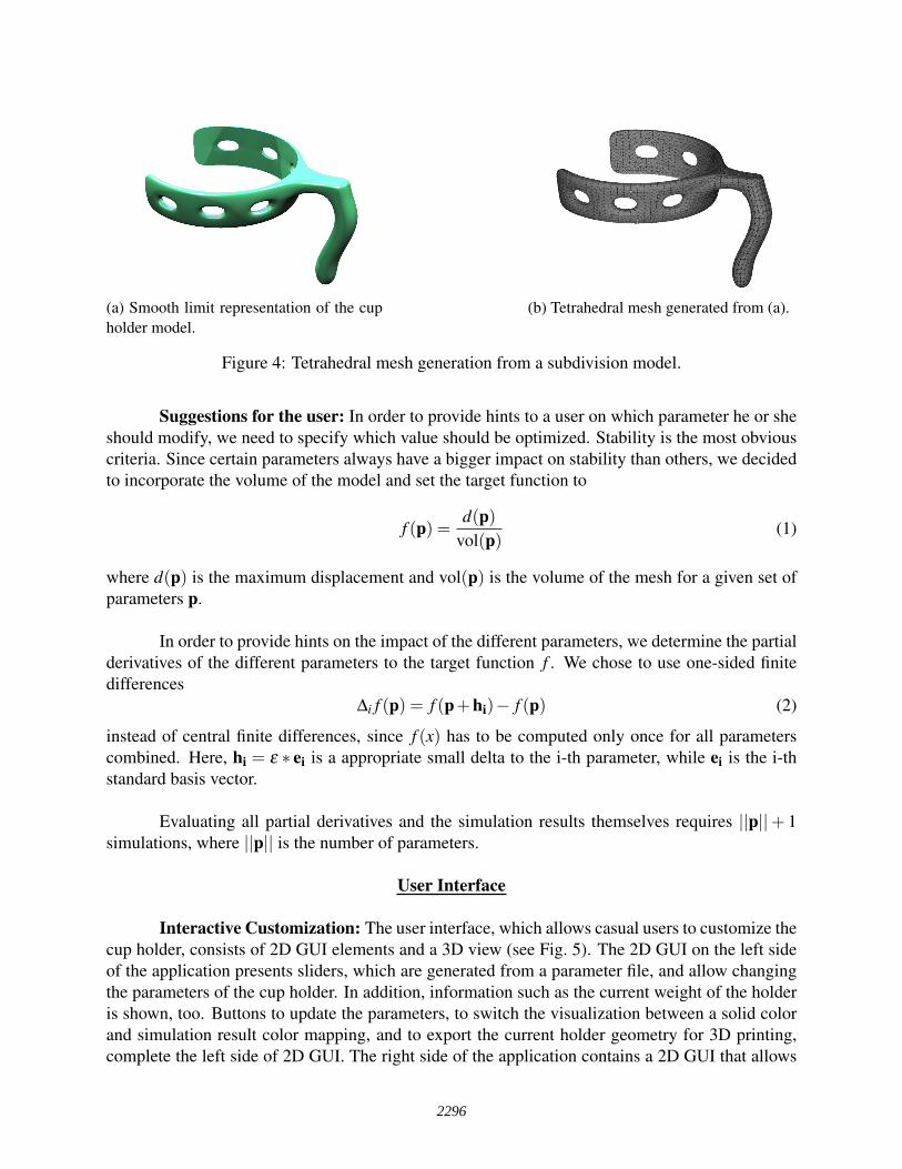
Interactive Customization: The user interface, which allows casual users to customize thecup holder, consists of 2D GUI elements and a 3D view (see Fig. 5). The 2D GUI on the left sideof the application presents sliders, which are generated from a parameter file, and allow changingthe parameters of the cup holder. In addition, information such as the current weight of the holderis shown, too. Buttons to update the parameters, to switch the visualization between a solid colorand simulation result color mapping, and to export the current holder geometry for 3D printing,complete the left side of 2D GUI. The right side of the application contains a 2D GUI that allows
2296
the manipulation of the color mapping. The key components of the 2D GUI at different stagesare highlighted using a workflow-based approach. For example, the color mapping is enabled andthe parameter sliders are disabled when simulation results are shown. The 3D view shows thecup with the holder standing on the ground. An interactive response to changes of the parametersvia the 2D GUI is achieved by caching of mathematical operands. The mathematical operandsare computed once when the initial model of the cup holder has been loaded and are then usedto evaluate the limit surface from the subdivision volume control mesh every time the parameterschange. This approach is similar to the pre-computation of the subdivision matrices as describedby Altenhofen et al. [9]. The updated design is visible in the 3D view shortly after the casual userchanged a parameter with a slider, allowing an interactive, iterative design process. Furthermore,the 3D view supports color mapped visualization of the current FEM results. The 3D view and the2D GUI elements support touch input, and therefore, allow a natural and fluent operation of thefront-end.
Figure 5: User Interface for casual users.
Asynchronous Communication: While the GPU solver presented in the previous sec-tion is highly efficient and achieves sub-second simulation times, asynchronous communicationwith the solver is used to reduce perceived delays even further. To achieve this goal, we im-plemented asynchronous communication and simulation cancellation via WebSocket-based (seeIETF RFC 6455 [27]) interprocess communication (IPC). WebSockets provide a reliable, ordered,message-based communication channel.
While the user manipulates the model’s parameters, the UI immediately messages the sim-ulation service with the new set of parameters. If no simulation is running yet, these parameters areapplied to the tetrahedral model used for simulation and a new simulation, including calculation
2297
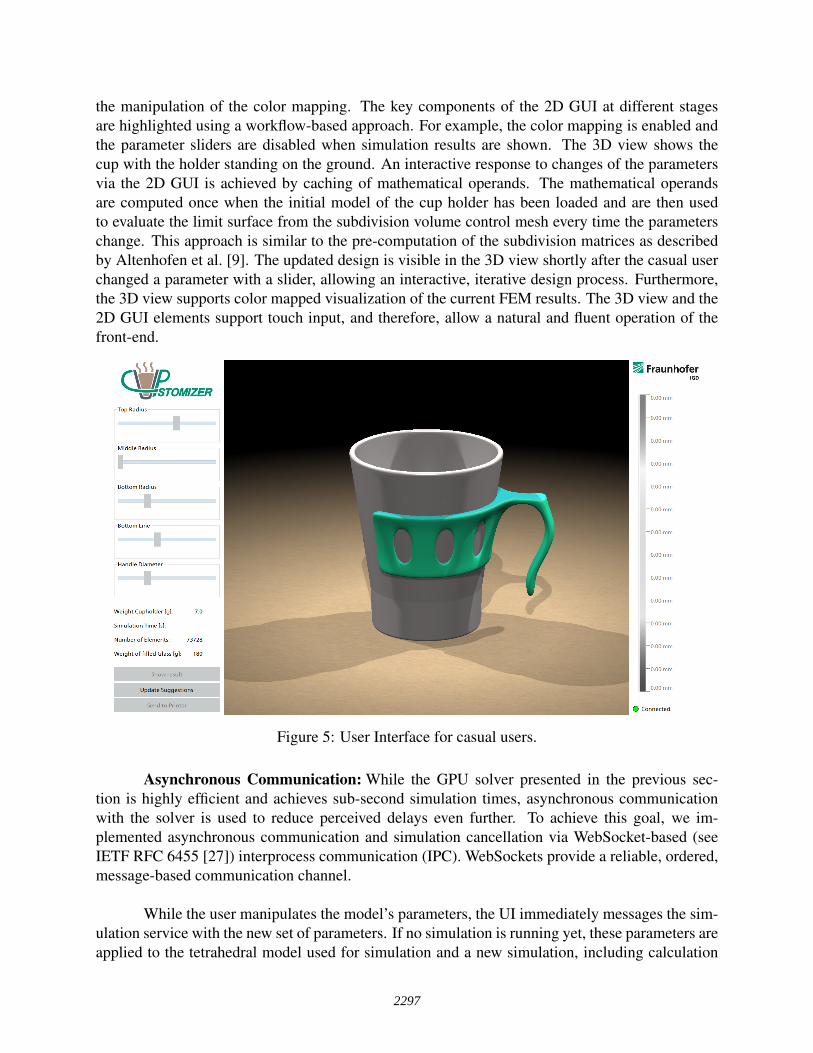
of derivatives, is triggered. If a simulation is already running, the running simulation is canceledbefore retriggering the simulation. An example sequence diagram is given in Fig. 6, which showsthe ideal case where the results are available before the user actively triggers simulation, reducingperceived latency to zero.
To support cancellation, several cancellation points were introduced into the simulationalgorithm. At these points, a cancellation condition is checked. If cancellation is requested, thecurrent simulation is interrupted and the cancellation is reported to the UI. Due to the synchro-nization costs between the protocol and simulation threads, as well as the GPU, these points areonly introduced at natural synchronization points, such as between derivative calculations or everyn iterations of the linear solver.
User UI Simulation
parameters 1simulate 1parameters 2simulate 2parameters 3simulate 3
canceled 1, 2
results 3
simulate display
Figure 6: Sequence diagram of an exemplary user interaction sequence including cancellation. Pa-rameter changes immediately trigger new simulation messages, and old simulations are canceled.In the ideal case, when the user clicks the “Simulate” button, the results are already available fordisplay.
Feedback for User Guidance: The 2D UI highlights the parameter with the highest impacton the target function, once the simulation back-end messages the suggestions to the front-end. Theslider of that parameter is visually highlighted to indicate in which direction the casual user maymove the slider to get a better result. Therefore, the slider background is split by the handle. Theside pointing to the better result gets a green background and the other one a red background asshown in Figure 7. The casual user has the possibility to change other parameters as well. Hence,the design can be adjusted to personal preferences at all times. More experienced users can togglethe visualization to show the simulation results color mapped from red to blue. Those users thencan directly see the critical regions and get an idea of how to improve the holder. In addition,
2298
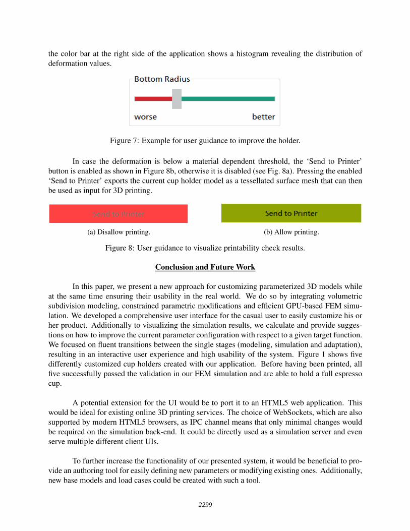
the color bar at the right side of the application shows a histogram revealing the distribution ofdeformation values.
Figure 7: Example for user guidance to improve the holder.
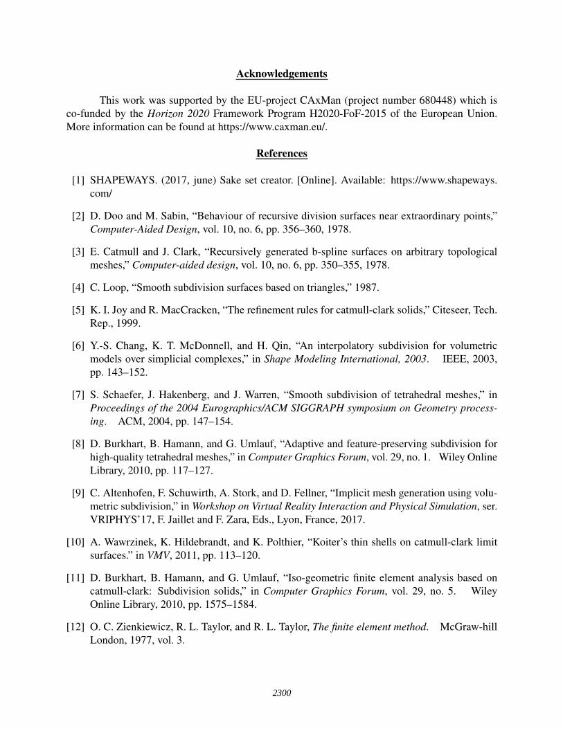
In case the deformation is below a material dependent threshold, the ‘Send to Printer’button is enabled as shown in Figure 8b, otherwise it is disabled (see Fig. 8a). Pressing the enabled‘Send to Printer’ exports the current cup holder model as a tessellated surface mesh that can thenbe used as input for 3D printing.
(a) Disallow printing. (b) Allow printing.
Figure 8: User guidance to visualize printability check results.
Conclusion and Future Work
In this paper, we present a new approach for customizing parameterized 3D models whileat the same time ensuring their usability in the real world. We do so by integrating volumetricsubdivision modeling, constrained parametric modifications and efficient GPU-based FEM simu-lation. We developed a comprehensive user interface for the casual user to easily customize his orher product. Additionally to visualizing the simulation results, we calculate and provide sugges-tions on how to improve the current parameter configuration with respect to a given target function.We focused on fluent transitions between the single stages (modeling, simulation and adaptation),resulting in an interactive user experience and high usability of the system. Figure 1 shows fivedifferently customized cup holders created with our application. Before having been printed, allfive successfully passed the validation in our FEM simulation and are able to hold a full espressocup.
A potential extension for the UI would be to port it to an HTML5 web application. Thiswould be ideal for existing online 3D printing services. The choice of WebSockets, which are alsosupported by modern HTML5 browsers, as IPC channel means that only minimal changes wouldbe required on the simulation back-end. It could be directly used as a simulation server and evenserve multiple different client UIs.
To further increase the functionality of our presented system, it would be beneficial to pro-vide an authoring tool for easily defining new parameters or modifying existing ones. Additionally,new base models and load cases could be created with such a tool.
2299
Acknowledgements
This work was supported by the EU-project CAxMan (project number 680448) which isco-funded by the Horizon 2020 Framework Program H2020-FoF-2015 of the European Union.More information can be found at https://www.caxman.eu/.
References
[1] SHAPEWAYS. (2017, june) Sake set creator. [Online]. Available: https://www.shapeways.com/
[2] D. Doo and M. Sabin, “Behaviour of recursive division surfaces near extraordinary points,”Computer-Aided Design, vol. 10, no. 6, pp. 356–360, 1978.
[3] E. Catmull and J. Clark, “Recursively generated b-spline surfaces on arbitrary topologicalmeshes,” Computer-aided design, vol. 10, no. 6, pp. 350–355, 1978.
[4] C. Loop, “Smooth subdivision surfaces based on triangles,” 1987.
[5] K. I. Joy and R. MacCracken, “The refinement rules for catmull-clark solids,” Citeseer, Tech.Rep., 1999.
[6] Y.-S. Chang, K. T. McDonnell, and H. Qin, “An interpolatory subdivision for volumetricmodels over simplicial complexes,” in Shape Modeling International, 2003. IEEE, 2003,pp. 143–152.
[7] S. Schaefer, J. Hakenberg, and J. Warren, “Smooth subdivision of tetrahedral meshes,” inProceedings of the 2004 Eurographics/ACM SIGGRAPH symposium on Geometry process-ing. ACM, 2004, pp. 147–154.
[8] D. Burkhart, B. Hamann, and G. Umlauf, “Adaptive and feature-preserving subdivision forhigh-quality tetrahedral meshes,” in Computer Graphics Forum, vol. 29, no. 1. Wiley OnlineLibrary, 2010, pp. 117–127.
[9] C. Altenhofen, F. Schuwirth, A. Stork, and D. Fellner, “Implicit mesh generation using volu-metric subdivision,” in Workshop on Virtual Reality Interaction and Physical Simulation, ser.VRIPHYS’17, F. Jaillet and F. Zara, Eds., Lyon, France, 2017.
[10] A. Wawrzinek, K. Hildebrandt, and K. Polthier, “Koiter’s thin shells on catmull-clark limitsurfaces.” in VMV, 2011, pp. 113–120.
[11] D. Burkhart, B. Hamann, and G. Umlauf, “Iso-geometric finite element analysis based oncatmull-clark: Subdivision solids,” in Computer Graphics Forum, vol. 29, no. 5. WileyOnline Library, 2010, pp. 1575–1584.
[12] O. C. Zienkiewicz, R. L. Taylor, and R. L. Taylor, The finite element method. McGraw-hillLondon, 1977, vol. 3.
2300
[13] M. Müller, J. Dorsey, L. McMillan, R. Jagnow, and B. Cutler, “Stable real-time deforma-tions,” in Proceedings of the 2002 ACM SIGGRAPH/Eurographics symposium on Computeranimation. ACM, 2002, pp. 49–54.
[14] A. Nealen, M. Müller, R. Keiser, E. Boxerman, and M. Carlson, “Physically based de-formable models in computer graphics,” in Computer graphics forum, vol. 25, no. 4. WileyOnline Library, 2006, pp. 809–836.
[15] D. Weber, J. Bender, M. Schnoes, A. Stork, and D. Fellner, “Efficient GPU data structures andmethods to solve sparse linear systems in dynamics applications,” Comput. Graphics Forum,vol. 32, no. 1, pp. 16–26, 2013.
[16] D. Weber, J. S. Mueller-Roemer, C. Altenhofen, A. Stork, and D. Fellner, “Deformation simu-lation using cubic finite elements and efficient p-multigrid methods,” Computers & Graphics,vol. 53, no. 2, pp. 185–195, 2015.
[17] N. SYSTEM. (2017, june) Radiolaria: bio-inspired design app. [Online]. Available:http://ne-r-v-o-u-s.com/radiolaria
[18] R. Gal, O. Sorkine, N. J. Mitra, and D. Cohen-Or, “iwires: an analyze-and-edit approach toshape manipulation,” in ACM Transactions on Graphics (TOG), vol. 28, no. 3. ACM, 2009,p. 33.
[19] M. Bokeloh, M. Wand, H.-P. Seidel, and V. Koltun, “An algebraic model for parameterizedshape editing,” ACM Transactions on Graphics (TOG), vol. 31, no. 4, p. 78, 2012.
[20] Autodesk. (2017, june) Autocad. [Online]. Available: http://www.autodesk.de/products/autocad/overview
[21] D. Systems. (2017, June) Solidworks. [Online]. Available: http://www.solidworks.de/
[22] N. Umetani, T. Igarashi, and N. J. Mitra, “Guided exploration of physically valid shapes forfurniture design,” ACM Transactions on Graphics (TOG), vol. 31, no. 4, p. 86, 2012.
[23] M. Shugrina, A. Shamir, and W. Matusik, “Fab forms: Customizable objects for fabricationwith validity and geometry caching,” ACM Transactions on Graphics (TOG), vol. 34, no. 4,p. 100, 2015.
[24] A. Schulz, J. Xu, B. Zhu, C. Zheng, E. Grinpun, and W. Matusik, “Interactive design spaceexploration and optimization for cad models,” ACM Transactions on Graphics, vol. 36, no. 4,July 2017.
[25] R. McNeel and Associates. (2017, June) Rhino. [Online]. Available: https://www.rhino3d.com/
[26] Autodesk. (2017, June) Autodesk maya. [Online]. Available: http://www.autodesk.de/products/maya/overview
[27] I. Fette and A. Melnikov, “The WebSocket protocol,” Internet Engineering Task Force(IETF), 2011. [Online]. Available: https://tools.ietf.org/html/rfc6455
2301