Integrated Vehicle-Based Safety Systems Preliminary Field Operational Test Plan
96
DOT HS 811 010 August 2008 Integrated Vehicle-Based Safety Systems Preliminary Field Operational Test Plan This document is available to the public from the National Technical Information Service, Springfield, Virginia 22161
Transcript of Integrated Vehicle-Based Safety Systems Preliminary Field Operational Test Plan

DOT HS 811 010 August 2008
Integrated Vehicle-Based SafetySystems Preliminary FieldOperational Test Plan
This document is available to the public from the National Technical Information Service, Springfield, Virginia 22161

This publication is distributed by the U.S. Department of Transportation, National Highway Traffic Safety Administration, in the interest of information exchange. The opinions, findings and conclusions expressed in this publication are those of the author(s) and not necessarily those of the Department of Transportation or the National Highway Traffic Safety Administration. The United States Government assumes no liability for its content or use thereof. If trade or manufacturers’ names or products are mentioned, it is because they are considered essential to the object of the publication and should not be construed as an endorsement. The United States Government does not endorse products or manufacturers.

Technical Report Documentation Page 1. Report No.
DOT HS 811 010 2. Government Accession No. 3. Recipient’s Catalog No.
4. Title and Subtitle
Integrated Vehicle-Based Safety Systems Preliminary Field Operational Test Plan
5. Report Date
August 2008 6. Performing Organization Code
052004 7. Author(s)
Sayer, J., LeBlanc, D., Bogard, S., Hagan, M., Sardar, H., Buonarosa, M. L., and Barnes, M.
8. Performing Organization Report No.
UMTRI-2008-7
9. Performing Organization Name and Address
The University of Michigan Transportation Research Institute (UMTRI) 2901 Baxter Road Ann Arbor, Michigan 48109-2150
10. Work Unit no. (TRAIS)
11. Contract or Grant No.
12. Sponsoring Agency Name and Address
U.S. Department of Transportation Research and Innovative Technology Administration ITS Joint Program Office
13. Type of Report and Period Covered
14. Sponsoring Agency Code
15. Supplementary Notes
16. Abstract
This document presents the plan for conducting a field operational test (FOT) of the Integrated Vehicle-Based Safety Systems (IVBSS) program. The plan describes the work that will be performed by the University of Michigan Transportation Research Institute using 16 passenger cars and 10 commercial trucks equipped with an integrated crash avoidance system.
The purpose of the IVBSS program is to evaluate the suitability of a state-of-the-art integrated crash warning system for widespread deployment in the U.S. passenger car and commercial truck fleet. Both platforms have three integrated crash-warning subsystem systems (forward crash, lateral drift, and lane-change/merge warnings); the light-vehicle platform also has a fourth subsystem, curve-speed warning.
For the light vehicle portion of the FOT, lay drivers will operate test vehicles in place of their own personal cars for a period of six weeks. Commercial-truck drivers from a commercial fleet will operate heavy trucks in place of the Class 8 tractors they normally use as their work vehicles.
All vehicles will be instrumented to capture information regarding the driving environment, driver activity, system behavior, and vehicle kinematics. Driver information will be captured through a series of subjective questionnaires, focus groups, and debriefing sessions to determine driver acceptance and to gain insight for improving future versions of integrated crash warning systems. 17. Key Words
Integrated Vehicle-Based Safety Systems, crash avoidance, collision avoidance, intelligent vehicles, crash warning systems
18. Distribution Statement
Unlimited
19. Security Classification (of this report)
None 20. Security Classification (of this page)
None 21. No. of Pages
89 22. Price
i

Table of Contents 1 Executive Summary.............................................................................................................. 11.1 Overview............................................................................................................................. 11.2 The IVBSS Program ........................................................................................................... 11.3 Extended Pilot Testing........................................................................................................ 21.4 Field Operational Test......................................................................................................... 21.5 FOT Data Collection and Analyses .................................................................................... 21.6 Summary ............................................................................................................................. 32 Introduction........................................................................................................................... 42.1 Program Overview.............................................................................................................. 42.2 Main Study Areas to Be Addressed .................................................................................... 5
2.2.1 Driver Acceptance of the Warning System .................................................................... 52.2.2 Effects on Driver Performance and Behavior................................................................. 6
2.3 Goals and Objectives of Extended Pilot Testing ................................................................ 62.4 Goals and Objectives of the FOT........................................................................................ 7
2.4.1 Light-Vehicle FOT Goals and Objectives ...................................................................... 72.4.2 Heavy-Truck FOT Goals and Objectives ....................................................................... 8
2.5 Pilot and Field Test Schedules............................................................................................ 82.5.1 Light-Vehicle Test Schedule........................................................................................... 82.5.2 Heavy-Truck Test Schedule............................................................................................ 9
2.6 Report Structure ................................................................................................................ 11 3 Extended Pilot Test Experimental Design ........................................................................ 123.1 Light-Vehicle Pilot Test Experimental Design................................................................. 12
3.1.1 Scope of Light-Vehicle Pilot Testing ........................................................................... 123.1.2 Characterization of the Light-Vehicle Pilot Testing Fleet............................................ 123.1.3 Light-Vehicle Participant Sampling Variables ............................................................. 133.1.4 Light-Vehicle Participant Recruitment ......................................................................... 133.1.5 Participant Orientation and Instruction for the Light-Vehicle Pilot Test ..................... 143.1.6 Light-Vehicle Schedule ................................................................................................ 14
3.2 Heavy-Truck Pilot Test Experimental Design.................................................................. 153.2.1 Scope of Heavy-Truck Pilot Testing............................................................................. 153.2.2 Characterization of the Heavy-Truck Pilot Testing Fleet ............................................. 153.2.3 Heavy-Truck Participant Sampling Variables .............................................................. 163.2.4 Heavy-Truck Participant Recruitment .......................................................................... 163.2.5 Participant Orientation and Instruction for the Heavy-Truck Pilot Test....................... 173.2.6 Heavy-Truck Schedule.................................................................................................. 17
4 FOT Experimental Design ................................................................................................. 184.1 Light-Vehicle FOT Experimental Design......................................................................... 18
4.1.1 Scope of the Light-Vehicle FOT................................................................................... 184.1.2 Characterization of the Light-Vehicle FOT Fleet ......................................................... 194.1.3 Sampling Variables for the Light-Vehicle FOT ........................................................... 194.1.4 Participant Recruitment for the Light-Vehicle FOT..................................................... 194.1.5 Participant Orientation and Instruction for the Light-Vehicle FOT ............................. 204.1.6 Assisting Light-Vehicle Participants in the Field ......................................................... 204.1.7 Schedule for the Light-Vehicle FOT ............................................................................ 21
iii

4.2 Heavy-Truck FOT Experimental Design.......................................................................... 214.2.1 Scope of the Heavy-Truck FOT.................................................................................... 214.2.2 Characterization of the Heavy-Truck Fleet................................................................... 224.2.3 Sampling Variables for the Heavy-Truck FOT ............................................................ 234.2.4 Participant Recruitment for the Heavy-Truck FOT ...................................................... 234.2.5 Participant Orientation and Instruction for the Heavy-Truck FOT .............................. 244.2.6 Assisting Heavy-Truck Participants in the Field .......................................................... 244.2.7 Schedule for the Heavy-Truck FOT ............................................................................. 25
5 Objective Data Collection................................................................................................... 265.1 The Objective Dataset....................................................................................................... 265.2 Light-Vehicle and Heavy-Truck Dedicated Instrumentation ........................................... 315.3 Camera Positioning for Video Collection......................................................................... 325.4 Video Data Compression and Sampling Rates ................................................................. 335.5 Audio Data Collection ...................................................................................................... 335.6 Data Acquisition System................................................................................................... 34
5.6.1 DAS Main Module........................................................................................................ 345.6.2 Modes of System Operation.......................................................................................... 36
5.7 DAS Remote Monitoring.................................................................................................. 395.8 DAS Data Retrieval .......................................................................................................... 40
5.8.1 Light-Vehicle Data Retrieval........................................................................................ 405.8.2 Heavy-Truck Data Retrieval ......................................................................................... 40
5.9 External Data Sources....................................................................................................... 415.9.1 Digital Maps.................................................................................................................. 415.9.2 GIS Data........................................................................................................................ 42 5.9.3 Crash History Data........................................................................................................ 425.9.4 National Radar Weather Data ....................................................................................... 425.9.5 Con-way Delivery Logs................................................................................................ 42
5.10 Participant Descriptors and Assessments.......................................................................... 435.10.1 Driver Biographical Information .................................................................................. 445.10.2 Michigan Driving Record ............................................................................................ 44
6 Subjective Data Collection ................................................................................................. 456.1 Participant Self-Characterization ...................................................................................... 45
6.1.1 Driver Behavior Questionnaire ..................................................................................... 456.1.2 Driving Style Questionnaire ......................................................................................... 45
6.2 Post-Drive Questionnaires ................................................................................................ 466.3 Post-Drive Debriefing....................................................................................................... 466.4 Focus Groups .................................................................................................................... 47 7 Management of the Light-Vehicle Fleet............................................................................ 487.1 Light-Vehicle Deployment Plan ....................................................................................... 487.2 Procedures for the Turnaround and Release of Light Vehicles ........................................ 49
7.2.1 Ensuring Integrity of Retrieved Data and DAS for Light Vehicles.............................. 497.2.2 Checkout Testing to Confirm Integrity of the Warning System Function.................... 507.2.3 Normal Vehicle Maintenance ....................................................................................... 51
7.3 Characterization of the Warning System Function........................................................... 517.4 Procedure for Responding to Incidents in the Field.......................................................... 51
iv

7.5 Light-Vehicle Deployment Plan ....................................................................................... 538 Management of the Heavy-Truck Fleet ............................................................................ 548.1 Characterization of the Warning Function........................................................................ 548.2 Ensuring Integrity of Ssytem Functionality for Heavy Trucks......................................... 568.3 Normal Vehicle Maintenance ........................................................................................... 578.4 Procedure for Responding to Incidents in the Field.......................................................... 578.5 Heavy-Truck Deployment Plan ........................................................................................ 589 Data Processing ................................................................................................................... 599.1 Adaptation of UMTRI’s Previous Data Model to the IVBSS Program ........................... 599.2 Data Validation ................................................................................................................. 61 9.3 Creation of Databases ....................................................................................................... 639.4 Transfer of Data to the Independent Evaluator................................................................. 649.5 Tools for Data Analysis .................................................................................................... 6510 Light-Vehicle Data Analysis............................................................................................... 6710.1 Analysis of Light-Vehicle Exposure Data ........................................................................ 6710.2 Analysis of System Performance in Light Vehicles ........................................................ 68
10.2.1 Availability of the Warning System ............................................................................. 7210.2.2 Crash Alerts and Advisories ......................................................................................... 69
10.3 Safety-Related Observations in Light Vehicles................................................................ 7110.3.1 Driver Responses to Events .......................................................................................... 7110.3.2 Changes in Conflict Management................................................................................. 7210.3.3 Changes in Pre-Conflict Driving Measures .................................................................. 7710.3.4 Changes in Secondary Task Behavior .......................................................................... 73
10.4 Driver Perceptions of the WArning System in Light Vehicles......................................... 7311 Heavy-Truck Data Analysis ............................................................................................... 7411.1 Analysis of Heavy-Truck Exposure Data ......................................................................... 7411.2 Analysis of the System Performance in Heavy Trucks ................................................... 75
11.2.1 Availability of the Warning System ............................................................................ 8111.2.2 Crash Alerts and Advisories ......................................................................................... 7611.2.3 Summary of Crash Alerts and Advisories .................................................................... 77
11.3 Safety Related Observations in Heavy Trucks ................................................................. 7811.3.1 Driver Responses to Events .......................................................................................... 7811.3.2 Changes in Conflict Management................................................................................. 7811.3.3 Changes in Pre-Conflict Driving Measures .................................................................. 79
11.4 Driver Perceptions of the Warning System in Heavy Trucks........................................... 7912 Final FOT Reports.............................................................................................................. 8113 Conclusions.......................................................................................................................... 8214 References............................................................................................................................ 83
v

List of Figures Figure 1. Light-vehicle test schedule (extended pilot and FOT) .................................................... 9
Figure 2. Heavy-truck test schedule (extended pilot and FOT).................................................... 10
Figure 3. Light-vehicle sensor coverage overview (not to scale) ................................................. 13
Figure 4. Light-vehicle extended pilot test schedule .................................................................... 14
Figure 5. Heavy-truck sensor suite overview (not to scale).......................................................... 16
Figure 6. Heavy-truck extended pilot test schedule...................................................................... 17
Figure 7. Light-vehicle field operational test schedule................................................................. 21
Figure 8. Heavy truck used in FOT .............................................................................................. 22
Figure 9. Heavy-truck field operational test schedule .................................................................. 25
Figure 10. Sample cabin and driver face images .......................................................................... 32
Figure 11. Sample forward image................................................................................................. 33
Figure 12. Sample left-side rear-looking image ........................................................................... 33
Figure 13. Major light-vehicle DAS components......................................................................... 35
Figure 14. DAS, vehicle, and user interface ................................................................................. 36
Figure 15. DAS mode control box................................................................................................ 37
Figure 16. Vehicle page of the light-vehicle GUI DAS................................................................ 38
Figure 17. Web interface for RDCW............................................................................................ 39
Figure 18. Plan-view of the Con-way facility at Romulus, Michigan .......................................... 41
Figure 19. Light-vehicle deployment schedule............................................................................. 53
Figure 20. Heavy-truck deployment schedule .............................................................................. 58
Figure 21. UMTRI data architecture............................................................................................. 60
Figure 22. Elements of a data definition channel and record ....................................................... 61
Figure 23. The UMTRI data viewer ............................................................................................. 66
List of Tables Table 1. Variations in the extended pilot FOTs by platform .......................................................... 2
Table 2. Variations in the FOT experimental designs by platform................................................. 2
Table 3. Variations in the extended pilot FOTs by platform ........................................................ 12
Table 4. Variations in the FOT experimental designs by platform............................................... 18
Table 5. DAS data collection variables......................................................................................... 28
Table 6. Driver assessment and descriptor summary.................................................................... 44
vi

List of Acronyms ACAS Automotive Collision Avoidance System ABS Antilock Braking System CDL Commercial Drivers License CSW Curve Speed Warning CWS Crash Warning System DAS Data Acquisition System DBQ Driver Behavior Questionnaire DSQ Driver Style Questionnaire DIU Driver Interface Unit DVI Driver-Vehicle Interface FAD Light-Vehicle Module for FCW, Arbitration, and DVI FCW Forward Collision Warning FOT Field Operational Test GUI Graphical User Interface HPMS Highway Performance Monitoring System HT Heavy Truck ISO International Organization for Standardization IVBSS Integrated Vehicle-Based Safety Systems LAM Look-Ahead Module LCM Lane Change-Merge warning LDW Lateral Drift Warning LV Light Vehicle NHTSA National Highway Traffic Safety Administration NPTS National Personal Transportation Survey RDCW Road Departure Crash Warning SHRP 2 Strategic Highway Research Program 2 TCP/IP Transmission Control Protocol/Internet Protocol TLX Task Load Index TTC Time to Collision U.S. DOT United States Department of Transportation UM University of Michigan UMTRI University of Michigan Transportation Research Institute VOC Voice of the Customer VORAD Vehicle Onboard RADar
vii


1 Executive Summary
1.1 Overview This document presents a preliminary plan for conducting a field operational test of the Integrated Vehicle-Based Safety Systems program. The plan covers the work that will be performed by the University of Michigan Transportation Research Institute using 16 passenger cars and 10 commercial trucks equipped with an integrated crash avoidance system.
This plan and its further development are collaborative and iterative processes that will engage the independent evaluators and the U.S. DOT. While the field test itself is to be discharged largely by UMTRI, the process of doing so must also satisfy the needs of the independent evaluators. The final version of this plan will be published in early 2009.
1.2 The IVBSS Program The purpose of the IVBSS FOT is to evaluate the suitability of a state-of-the-art integrated crash warning system for widespread deployment in the U.S. passenger car and commercial-truck fleet. The system to be tested was developed and implemented by Visteon and Cognex on the light-vehicle platform, and developed and implemented by Eaton and Cognex on the heavy-truck platform. Both platforms have the following integrated crash warning subsystems:
• Forward crash warning (FCW), which warns drivers of the potential for a rear-end crash with another vehicle;
• Lateral drift warning (LDW), which warns drivers that they may be drifting inadvertently from their lane or departing the roadway; and
• Lane-change/merge warning (LCM), which warns drivers of possible unsafe lateral maneuvers based on adjacent or approaching vehicles in adjacent lanes, and includes full-time side object presence indicators.
In addition, the light-vehicle platform also includes the curve-speed warning (CSW), which warns drivers that they are driving too fast into an upcoming curve and as a result, might depart the roadway.
For the light vehicle portion of the FOT, lay drivers will be recruited and will receive equipped research vehicles to drive in place of their own personal cars for a period of six weeks. Commercial-truck drivers from a commercial fleet will operate equipped heavy trucks in place of the Class 8 tractors they normally drive for work. In both instances, a comprehensive set of objective and subjective data will be collected and used to evaluate the system effectiveness and driver acceptance of integrated system.
Vehicles will be instrumented to capture information regarding the driving environment, driver activity, integrated system behavior, and vehicle kinematics. Driver information will be captured through a series of subjective questionnaires, focus groups, and debriefing sessions, to gather information regarding driver acceptance of the system and to gain insight into improving future versions of the integrated crash warning system.
1

1.3 Extended Pilot Testing The conduct of extended pilot testing was an original requirement of the IVBSS program. Extended pilot testing uses a small number of participants to obtain early feedback on driver acceptance and to ensure the integrated system operate as planned. With few exceptions, the extended pilot FOTs will be conducted almost identically to the full FOTs, but with shorter durations and without baseline periods. Table 1 provides an overview of the scope planned for extended pilot testing. The plan is that participants in the extended pilot tests would receive the same types of training, monitoring, and post-drive interaction that FOT participants would receive, although the extended pilot test would also examine these testing procedures, revising as necessary.
Table 1. Variations in the extended pilot FOTs by platform
Light Vehicle Heavy Truck
• 12 participants • Multiple drivers (approx. six) • Four research vehicles • One research tractor • 19-day exposures • Two-month exposure in fleet
1.4 Field Operational Test There are several considerations that influence the FOT experimental design, in particular the required number of participants to achieve statistically reliable results (sample size) and the capacity of data storage in the onboard data acquisition system, or DAS. Experimental designs for both light-vehicle and heavy-truck platforms are proposed for consideration with modifications to be made on the basis of further discussion among UMTRI, the U.S. DOT, and the independent evaluator. Table 2 provides an overview of the scope planned for the FOT.
Table 2. Variations in the FOT experimental designs by platform
Light Vehicle Heavy Truck
• 108 participants • 20 participants • 16 research vehicles • 10 research tractors • 40-day exposure/driver: • 2 shifts (daytime and nighttime)
- 12-day baseline period • 10-month exposure in fleet: - 28-day treatment period - 3-month baseline
- 7-month treatment period
1.5 FOT Data Collection and Analyses A significant body of objective data describing vehicle and warning system performance will result from the conduct of the FOT, and this data will be critical to assessing any safety benefits attributable to the crash avoidance system. Additional data that will be key are the subjective assessments provided by the participants that use the system in order to assess driver acceptance.
2

This report provides an overview of the analysis that is planned by UMTRI using the FOT data. When appropriate, special methods of analysis are described when they may affect the success of addressing the study questions. Otherwise, UMTRI will rely on numerous analytical approaches that it has previously developed or used in the evaluation of FOT data.
Generally speaking, the proposed analyses can be described as falling into one of four major study areas: exposure analyses; warning system performance analyses; safety-related observations; and driver perceptions and acceptance of the integrated system. In addition to these study areas, data from the FOT can be expected to provoke questions and observations that were unexpected during the planning stage. These discoveries may be significant enough to influence the tactics used to address the main study questions.
While UMTRI will perform various analyses of the data, all data will be transferred to Volpe on a regular basis. Ultimately it will be the independent evaluator that provides the final assessment of the system’s acceptance and benefits.
1.6 Summary The FOT plan summarizes all field-testing activity anticipated on the IVBSS program for Phase II. It is, however, a preliminary plan, as UMTRI views this as a collaborative and iterative process that will engage the independent evaluators and U.S. DOT. Nonetheless, on the basis of previous FOTs that UMTRI has successfully conducted, what is outlined in this document serves as a solid basis on which to further our discussions with U.S. DOT and as a guide the later stages of Phase II of the IVBSS program.
3
2 Introduction This document constitutes the preliminary field operational test plan for conducting a field evaluation of the collision avoidance system developed under the Integrated Vehicle-Based Safety Systems program. The plan covers the work that will be discharged primarily by UMTRI using a 26-vehicle fleet (16 passenger cars and 10 commercial trucks) equipped with the integrated safety system. The FOT will yield a set of data that will be provided to the program’s independent evaluator, the Volpe National Transportation Systems Center. The goal of the FOT is to evaluate the integrated safety system in terms of its effectiveness in helping to reduce crashes and to gauge driver acceptance of the system. It is recognized that the Volpe team has developed its own evaluation plan, outlining its intent to analyze the data that are identified for collection here. Volpe’s data needs have been integrated with those of the UMTRI-led partners in determining elements of this preliminary FOT plan. Nevertheless, revisions to this plan are likely to take place under further collaboration with Volpe.
The UMTRI-led team sees the experimental design and development of a data collection plan as a collaborative process that will engage the independent evaluators and the U.S. DOT. The field test itself is to be conducted largely by UMTRI following procedures that are described here for managing participants, the test fleet, and the data archives. Although the data is to be transferred to Volpe on a regular basis throughout the field test, both Volpe and UMTRI intend to begin the analysis and inquiry into this data while testing in underway. The plan for UMTRI analysis of FOT data is presented in this report, as is an outline for documenting the FOT methods and results upon completion of testing.
2.1 Program Overview The purpose of the IVBSS FOT is to evaluate the suitability of a state-of-the-art integrated crash warning system for widespread deployment in the U.S. passenger car and commercial truck fleet. The system to be tested was developed and implemented by Visteon and Cognex on the light-vehicle platform, and developed and implemented by Eaton and Cognex on the heavy-truck platform. Both platforms have the following integrated crash warning subsystems:
• Forward crash warning, which warns drivers of the potential for a rear-end crash with another vehicle;
• Lateral drift warning, which warns drivers that they may be drifting inadvertently from their lane or departing the roadway; and
• Lane-change/merge warning, which warns drivers of possible unsafe lateral maneuvers based on adjacent or approaching vehicles in adjacent lanes, and includes full-time side object presence indicators.
In addition, the light-vehicle platform also includes the curve-speed warning, which warns drivers that they are driving too fast into an upcoming curve and as a result, might depart the roadway.
Two sets of drivers will be recruited, one for the light-vehicle platform and one for heavy trucks; each will receive an equipped research vehicle to drive. Lay drivers will be recruited to drive the light vehicles in place of their own personal cars. Commercial truck drivers from a commercial
4

fleet will be recruited to drive vehicles on the heavy-truck platform in place of the Class 8 tractors they normally drive on the job. In both instances, a comprehensive set of objective and subjective data will be collected and used to evaluate system effectiveness and driver acceptance. The vehicles will be instrumented to capture information regarding the driving environment, driver activity, integrated warning system behavior, and vehicle kinematics. Driver information and acceptance of the warning system are captured through a series of subjective questionnaires, focus groups, and debriefing sessions to gather information regarding driver acceptance and to gain insight for improving future versions of the system.
An FOT differs from most designed experiments by the extent of its naturalism, or lack of control over the majority of test conditions. Participants will drive the equipped vehicles in place of their personal cars or work vehicles, going wherever, whenever, and however they choose. The driving is thereby largely unmanaged by the research team and derives, instead, from either the personal mobility needs of the individual participants (in the case of the light-vehicle platform), or the commercial delivery needs of the truck fleet taking part in the FOT. Thus, experimental control lies only in the commonality of the test vehicles that are driven, the sampling plan through which drivers are selected, and the types of data obtained for documenting the experience. Yet, even these controls are not common between the light-vehicle and heavy-truck platforms.
2.2 Main Study Areas to Be Addressed Data from the FOT can be used as the basis for answering many questions concerning the warning system and how drivers used it. The FOT analysis will address three broad study areas:
• Driver acceptance and driver understanding of the crash warning system; • Driving performance and driver behavior with and without the system, including safety-
related findings; and • Potential successes and challenges of integrated crash warning products, when deployed.
2.2.1 Driver Acceptance of the Warning System Driver acceptance of the warning system will be examined using analyses of subjective responses in conjunction with observed use of, interaction with, and response to the system. Acceptance by drivers is one of the fundamental questions to be addressed by the FOT. While integrated crash warning systems may be technically feasible and sound, the general premise that such systems will be widely accepted by drivers remains unclear. This FOT will examine driver acceptance of integrated crash warning systems having functionalities similar to those of the fielded system.
Some key attributes on which the system will be assessed include driver comfort, utility, and convenience. Overall, driver acceptance of the warning system will be performed using analyses of subjective responses in conjunction with observed system use, system adjustment by the driver, and driver response to the presentation of system warnings. The key attributes on which the driver acceptance of the system will be assessed includes, but is not limited to:
• Comfort: Assessment primarily of the system’s ability to convey the necessary warnings in a clear, logical, and timely manner;
5
• Convenience: The relative ease of learning and using the system; and • Utility: The range of driving conditions in which the system is perceived to provide
benefit and the relative worth of such benefit, including perceived safety value and willingness to purchase.
The primary method for assessing driver acceptance will be through questionnaires. However, driver acceptance will also be assessed through direct interaction between researchers and participants in post-drive debriefings and focus groups held after exposure to the system.
Important secondary sources of data for examining driver acceptance and understanding of the system include data collected onboard the vehicle. Onboard measurements will describe what drivers were exposed to, in terms of their driving behavior, route choices, and the resulting system feedback. Because system performance is strongly dependent on driving behavior and the conditions of the driving environment, the following subjective and objective data are needed to understand driver acceptance as it relates to specific driving conditions:
• Changes in driver performance relating directly to warning modalities including the frequency of significant lane exceedance, coming into close proximity to other vehicles while performing lane changes or merges, and coming into close proximity to the rear of other, slower moving vehicles ahead; and
• Overall driving patterns that may be relevant to the potential for the warning system, such as the general distribution of lane-keeping performance, speed decrements and deceleration peaks, turn signal use, and other observed lateral-control and forward conflicts.
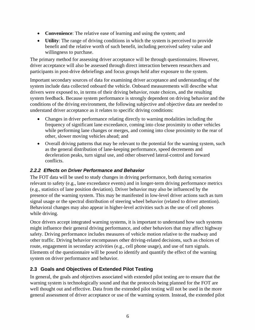
2.2.2 Effects on Driver Performance and Behavior The FOT data will be used to study changes in driving performance, both during scenarios relevant to safety (e.g., lane exceedance events) and in longer-term driving performance metrics (e.g., statistics of lane position deviation). Driver behavior may also be influenced by the presence of the warning system. This may be manifested in low-level driver actions such as turn signal usage or the spectral distribution of steering wheel behavior (related to driver attention). Behavioral changes may also appear in higher-level activities such as the use of cell phones while driving.
Once drivers accept integrated warning systems, it is important to understand how such systems might influence their general driving performance, and other behaviors that may affect highway safety. Driving performance includes measures of vehicle motion relative to the roadway and other traffic. Driving behavior encompasses other driving-related decisions, such as choices of route, engagement in secondary activities (e.g., cell phone usage), and use of turn signals. Elements of the questionnaire will be posed to identify and quantify the effect of the warning system on driver performance and behavior.
2.3 Goals and Objectives of Extended Pilot Testing In general, the goals and objectives associated with extended pilot testing are to ensure that the warning system is technologically sound and that the protocols being planned for the FOT are well thought out and effective. Data from the extended pilot testing will not be used in the more general assessment of driver acceptance or use of the warning system. Instead, the extended pilot
6

tests are an opportunity to perform a “full dress rehearsal” of the FOT, and still have the opportunity to make minor adjustments prior to conducting the FOT. In this manner, the likelihood of encountering unanticipated events that may otherwise have occurred by proceeding directly into an FOT can be significantly reduced.
The entire integrated warning system, including the data acquisition system, will be evaluated in pilot testing to ensure that the systems are behaving in accordance with the functional requirements and that the data can be reliably retrieved. Each platform will have its own pilot test where a small number of drivers will be recruited and instructed on using the system. The drivers will then be provided equipped vehicles for shorter durations (approximately half as long as the FOT) in order to experience the system, but also to expose the research vehicle as a whole to conditions that are representative to those that are expected in the actual FOT.
Driver acceptance may play a role in the outcome of extended pilot testing to the extent that drivers may or may not approve of the system’s performance. In the event that performance is not judged to be adequate by pilot test participants, changes would have to be carefully considered and revisions made only as necessary. The recruitment and instruction segments of the protocols will also be closely examined in conducting the extended pilot tests. Feedback from participants will be key in making any decisions on whether modifications to the protocol are required.
2.4 Goals and Objectives of the FOT The primary goal of the FOT is to determine the practical suitability of the integrated warning system for widespread use on public roadways in both passenger vehicles and heavy trucks. Suitability for widespread use will be determined by the extent to which the installed systems (1) are deemed acceptable and easy to use; (2) yield safety benefits; and (3) pose minimal added risk.
To reach the goals of the FOT, it is necessary to obtain the users’ appraisal of the system and to make an objective assessment of how it impacts the driving process. The unstructured character of naturalistic driving requires an investigative approach in making the objective assessment, and the extensive data set will need to be mined through creative inquiry modeled after similar previous UMTRI efforts.
2.4.1 Light-Vehicle FOT Goals and Objectives Goals and objectives specific to the light-vehicle platform include ensuring that the system functions as intended on the Honda Accord, and that lay drivers find it acceptable in terms of its performance and ease of use. Because participants in the light-vehicle FOT will represent a random sample of licensed drivers with a wide range of driving experience and skills, the ability of the system to satisfy driver expectations may be challenging. Nonetheless, it is important that a wide range of driver characteristics be examined in order to better predict the suitability of similar systems for future implementation by vehicle manufacturers.
Particular elements of the data that will be closely examined to determine their relationship with system acceptance and benefit will include driver age and gender, driving style, road class, weather, propensity to engage in secondary tasks (e.g., using a cellular telephone), exposure to the system (both in terms of miles driven and time), the frequency of warnings, and the types of
7

warnings received by drivers. Examination and analyses of these elements and the associated data will help to better characterize those aspects of the system that are either acceptable or unacceptable to drivers, and those circumstances under which it provides safety benefits.
2.4.2 Heavy-Truck FOT Goals and Objectives Goals and objectives specific to the heavy-truck platform include ensuring that the warning system functions as intended on the International ProStar 8600-series tractor, and that commercial drivers find the system acceptable in terms of its performance and ease of use. Participants in the heavy-truck portion of the FOT will represent a sample of commercial drivers operating within a freight carrier’s fleet.
Particular elements of the data that will be closely examined to determine their relationship with system acceptance and benefits will include driver age, delivery route types (long- or short-haul), road class, weather, propensity to engage in secondary tasks such as using a cell phone, exposure to the system both in terms of miles driven and time, the frequency of warnings, and the types of warnings received by drivers. Examination and analyses of these elements and the associated driving performance data will help to better characterize those aspects of the warning system that are either acceptable or unacceptable to drivers, and those circumstances under which it provides safety benefits. Feedback from the fleet operator, and truck owners, will also be important in determining the long-term viability of similar systems in commercial vehicles, as the fleet operators are ultimately the safety system purchasers in the majority of the commercial-truck market. Every attempt will be made to recruit participants in a manner that the data provided by the FOT represent reasonable samples based upon driver age and delivery route type. UMTRI will work with the independent evaluator to determine target sample sizes on the basis
2.5 Pilot and Field Test Schedules Provide a high-level schedule outlining major milestones that will be addressed by the FOT for each platform.
2.5.1 Light-Vehicle Test Schedule Figure 1 illustrates key Phase II tasks and the associated dates currently anticipated for the light vehicle platform.
8

Figure 1. Light-vehicle test schedule (extended pilot and FOT)
2.5.2 Heavy-Truck Test Schedule Figure 2 illustrates key Phase II tasks and the associated dates currently anticipated for the heavy truck platform.
9

Figure 2. Heavy-truck test schedule (extended pilot and FOT)
10

2.6 Report Structure The remainder of this report is organized as follows:
Section 3 describes the extended pilot test experimental design for both light-vehicle and heavy-truck platforms, including scope, participant sampling variables, participant recruitment, and schedules.
Section 4 discusses the FOT experimental design for both light-vehicle and heavy-truck platforms, including scope, participant sampling variables, participant recruitment, and schedules.
Section 5 covers objective data collection, including onboard and external data sources, and the light-vehicle and heavy-truck data acquisition systems.
Section 6 covers subjective data collections, including participant self-characterizations, post-drive questionnaires, and focus groups.
Section 7 describes management of the light-vehicle fleet, including the development plan, turnaround and release of vehicles, integrity of data, vehicle maintenance, and response to incidents in the field.
Section 8 describes management of the heavy-truck fleet, including the development plan, vehicle assignment, integrity of data, vehicle maintenance, and response to incidents in the field.
Section 9 discusses data processing, including adaptation of a previous data model to the IVBSS program, data validation, database creation, data transfer, and data analysis tools.
Section 10 describes light-vehicle data analysis of exposure data, driving environment, system performance (as a whole and as separate subsystems), and driver perception.
Section 11 describes heavy-truck data analysis of exposure data, driving environment, system performance as a whole and as separate subsystems, and driver perception.
Section 12 discusses the final reports for both light-vehicle and heavy-truck platforms.
Section 13 provides conclusions from the field operational tests.
Section 14 contains the list of references.
11

3 Extended Pilot Test Experimental Design One of the original requirements of the IVBSS program is that pilot FOTs, using a small number of participants to obtain early feedback on driver acceptance and ensure that the integrated system operates as planned, must be conducted on both vehicle platforms prior to the actual FOT. With few exceptions, the pilot FOTs are conducted almost identically to the future full FOTs, but with shorter durations and without a baseline period. Table 2 provides a brief overview of the scope planned for the extended pilot testing, with greater detail provided in following sections. Participants in the extended pilot tests would receive the same types of training, monitoring, and post-drive interaction that FOT participants would receive, although the extended pilot test would also examine these procedures, revising them as necessary.
Table 2. Variations in the extended pilot FOTs by platform
Light Vehicle Heavy Truck
• 12 participants • About 6 drivers • 4 research vehicles • 1 research tractor • 19-day exposures • 2-month exposure in fleet
3.1 Light-Vehicle Pilot Test Experimental Design
3.1.1 Scope of Light-Vehicle Pilot Testing For the light-vehicle platform, the extended pilot test would include the use of 4 prototype vehicles and 12 participants. The vehicles will collect virtually all of the same data that is planned for the actual FOT. Participants will receive training on the use of the safety system and the research vehicles, and then be expected to use the equipped Honda Accords in place of their own vehicles for a 19-day duration. One difference between the extended pilot test and the FOT is that there will be no baseline period of data collection in the extended pilot test. This will maximize both exposure to the system and insights from the participants regarding the safety system. Furthermore, a baseline period is not needed, as the extended pilot data will not be analyzed in the same fashion that the FOT data, nor would data from 12 participants be sufficient to draw conclusions regarding changes in driver behavior that might be associated with the system. Instead the emphasis will be on subjective impressions of the system and ensuring that the crash warning system is functioning properly.
3.1.2 Characterization of the Light-Vehicle Pilot Testing Fleet
The integrated warning system was installed in six 2006 Accord EXs during Phase I of the program for development purposes. Four of these development vehicles will be updated as necessary and used in the extended pilot test. Each vehicle contains a light-vehicle warning system having curve speed warning, forward collision warning, lane-change/merge warning, and lateral drift warning systems integrated into a safety system with a unified driver-vehicle interface. Figure 3 provides a graphic representation of the sensor suite and zones of coverage.
12

Figure 3. Light-vehicle sensor coverage overview (not to scale)
These vehicles will be modified to include the complement of sensors for monitoring driver behavior, including their participation in secondary tasks that was not implemented during system development, and as such, would be representative of vehicles ready for FOT deployment. This will include video cameras collecting images both inside and surrounding the vehicle, an in-cabin microphone, and data stored using an onboard data acquisition system designed specifically for the field operational test.
3.1.3 Light-Vehicle Participant Sampling Variables Of the 12 participants selected for the extended pilot test, 4 will come from each of three age groups: 20 to 30, 40 to 50, and 60 to 70 years old. An equal number of male and female participants will be selected for each age group. Prospective participants having any felony motor vehicle convictions, such as driving while intoxicated or under the influence of alcohol, within 36 months of recruitment will be excluded from the extend pilot test.
3.1.4 Light-Vehicle Participant Recruitment Participants will be recruited with the assistance of the Michigan Secretary of State (the State’s driver licensing bureau). As in other FOTs UMTRI has conducted, a random sample of a few hundred driving records would be drawn from the Secretary of State’s database for the population of licensed drivers from eight counties surrounding Ann Arbor (all within a 1.5-hour
13

drive of UMTRI). These individuals will receive a postcard informing them that they qualify to participate in a study of new automotive technologies being conducted by UMTRI, and to call an 800 number if interested in learning more about participating. This sampling strategy would help ensure a wide geographical area that includes urban (where lane change conflicts are likely to be greater), suburban, and rural (where single-vehicle road departures are concentrated) driving conditions. All information obtained through State records would be treated with strict confidentiality.
3.1.5 Participant Orientation and Instruction for the Light-Vehicle Pilot Test Participant orientation and training will begin with an introduction to the research vehicle and the warning system as provided in an instructional video developed by UMTRI. A briefing and opportunity to ask questions of a researcher will follow. The video will cover two principle areas: the location of standard controls and displays on the research vehicles, including use of the vehicle’s safety equipment (air bag, seat belt, ABS, etc.), and all usability aspects of the system, including video examples of circumstances in which participants could expect to receive alerts or warnings.
Participants will also receive hands-on instruction with the research vehicle and the warning system. The experimental apparatus will be identified and their purposes explained. Participants will observe each warning or state in a static demonstration. Then, while accompanied by a researcher, each participant will experience the system in operation as a driver during an orientation run. This drive will last about 30 minutes and will take place on local roadways in normal traffic. The researcher who provides the orientation will thereafter be the primary point of contact for the participant should any questions or concerns arise.
Once participants complete the orientation and are comfortable with their understanding of the research vehicle, they will be free to leave with the vehicle, at which time a date and time to return the vehicle will be scheduled. The glove compartment of each vehicle will include the following informational material: the scheduled vehicle return date, a copy of the instructional videotape on VHS and DVD (as well a manual outlining all the material included in the video for persons without access to DVD or videotape players), a road map of Michigan, a log book in which to make comments, emergency contact information, a copy of the informed-consent form, and proof of insurance.
3.1.6 Light-Vehicle Schedule Figure 4 shows the major milestones for the light-vehicle extended pilot test.
Figure 4. Light-vehicle extended pilot test schedule
14

3.2 Heavy-Truck Pilot Test Experimental Design
3.2.1 Scope of Heavy-Truck Pilot Testing The extended pilot test would be run using a terminal and drivers who are part of the larger Con-way fleet, but not the same terminal or drivers who would be selected for the FOT. At least six drivers would participate in the extended pilot test. The terminal of choice is the Ann Arbor-Whitmore Lake terminal in part given its proximity to UMTRI in the event that troubleshooting of the unit is necessary and in part to aid in the collection of data from the units. A single International tractor equipped with the crash warning system will be deployed at the terminal for two months. This period would allow 6 to 8 drivers to experience the system for one to two weeks each. The equipped truck will be used on regular Con-way routes to conduct scheduled deliveries. Routes and drivers will be selected in order to maximize the range of driving environments to which the vehicle is exposed (urban or suburban, surface street or highway, etc.).
There would be no baseline period, as the extended pilot data will not be analyzed in the same fashion that the FOT data is analyzed, nor would data from 6 to 8 participants be sufficient to draw conclusions regarding changes in driver behavior that might be associated with the warning system. Instead, emphasis will be placed on the subjective impressions of the system, ensuring that it is functioning properly while evaluating the FOT protocol. Subjective data collection will be carried out in the HT extended pilot using either an on-line or printed version of the survey, depending upon the driver’s preference. Only drivers will serve as formal participants, but it may be the case that informal feedback is provided to UMTRI from the terminal management.
3.2.2 Characterization of the Heavy-Truck Pilot Testing Fleet The warning system is being installed in a single International ProStar 8600-series tractor that meets Con-way’s specifications established during Phase I of the program. This vehicle will be used in the extended pilot test, and lent to Con-way for two months to be used in place of one or more existing tractors. The tractor contains the heavy-truck warning system (forward collision warning, lane-change or merge warning, and lateral drift warning systems in an integrated safety system with a unified driver-vehicle interface). UMTRI will monitor the health of the fleet remotely using data transferred over the DAS cell modem. At the end of each trip (ignition off), this data will be sent directly to the servers at UMTRI and uploaded onto Web pages for review. This process is described in Section 9.2, Data Validation. Figure 5 provides a graphic representation of the sensor suite and zones of coverage.
15

Figure 5. Heavy-truck sensor suite overview (not to scale)
This vehicle will include the complement of sensors for monitoring driver behavior that was not implemented during system development, and as such would be representative of vehicles ready for FOT deployment. This tractor will be retained on loan to UMTRI from International Truck for the duration of the IVBSS program, and lent to Con-way during the FOT should one of the 10 FOT tractors be out of service. Additional sensors on the tractor include video cameras collecting images both inside and surrounding the vehicle, an in-cabin microphone, and data stored using an onboard data acquisition system designed specifically for the FOT. In addition to collecting these measures, a substantive quality control process will be used to ensure data channel accuracy. This process is described in Section 9.2, Data Validation.
3.2.3 Heavy-Truck Participant Sampling Variables UMTRI will attempt to select the 6 or more drivers from a variety of age ranges and years of experience in operating heavy trucks. However, driver age is most likely to range between 30 and 55 years old. The Ann Arbor-Whitmore Lake terminal is small and has fewer drivers than the terminal to be used for the FOT. Participation will be strictly voluntary.
3.2.4 Heavy-Truck Participant Recruitment Drivers will be recruited by an UMTRI representative addressing the terminal staff during a regularly scheduled driver information session. Recruitment will include a description of the warning system, and will allow the terminal drivers to inspect an equipped tractor and ask questions of UMTRI staff. After drivers are chosen, their Michigan driving records will be obtained. Additionally, since it is possible that a line-haul driver could have had a crash in another State and not have that crash appear on the driver’s Michigan driving record, drivers will be asked to report all crashes in which they have been involved while driving a commercial truck for the past five years. Detailed information regarding driver history with commercial vehicles, such as the number of years that they have held a CDL and their years of service with Con-way, will be obtained.
16

3.2.5 Participant Orientation and Instruction for the Heavy-Truck Pilot Test Driver training will begin with an introduction to the research vehicles and the warning system with an opportunity to ask specific questions of a research associate. The introduction will concentrate on the system’s usability aspects, including video examples of circumstances in which a driver could expect to receive a warning. This will include an explanation of what each system does, how it works, and how to identify any operational problems. The experimental apparatus will be identified and their purposes explained. Each driver will be given an FOT manual that contains all the information covered in the training session, along with contact information and samples of “driver event” forms. Copies of this material will also be kept in each of the FOT tractors for the duration of the study, as well as a log book in which to make comments and emergency contact information. Drivers will also receive hands-on instruction in an equipped tractor. While accompanied by a researcher, each driver will experience the system first-hand during an orientation drive of approximately 30 minutes on local roadways in normal traffic. The researcher who provides the orientation will thereafter be the primary point of contact for the driver should any questions or concerns arise.
3.2.6 Heavy-Truck Schedule Figure 6 shows the major milestones for the heavy-truck extended pilot test.
Figure 6. Heavy-truck extended pilot test schedule
17

4 FOT Experimental Design The UMTRI-led team acknowledges that the development of the experimental designs should be a collaborative process where the they will work with the U.S. DOT and Volpe on defining the plans for sampling, exposure, screening, etc. However, there are several considerations that influence the FOT experimental design, in particular the required number of participants to achieve statistically reliable results (sample size) and the capacity of data storage in the onboard data acquisition system. Experimental designs for both light-vehicle and heavy-truck platforms are proposed for consideration, with modifications to be made on the basis of further discussion among UMTRI, the U.S. DOT, and the independent evaluator. Table 3 provides a brief overview of the scope planned for the FOT, with greater detailed provided in following sections.
Table 3. Variations in the FOT experimental designs by platform
Light Vehicle Heavy Truck
• 108 participants • 20 participants • 16 research vehicles • 10 research tractors • 40-day exposure/driver: • 2 shifts (daytime and nighttime)
- 12-day baseline period • 10-month exposure in fleet: - 28-day treatment period - 3-month baseline
- 7-month treatment period
4.1 Light-Vehicle FOT Experimental Design
4.1.1 Scope of the Light-Vehicle FOT Sixteen late-model Honda Accords will be used as research vehicles for the participants. One additional vehicle will serve as a backup should a vehicle in the field develop problems. At least 108 passenger car drivers will take part in the FOT, and the sample will be stratified by age and gender. The age groups to be examined are 20 to 30, 40 to 50, and 60 to 70 years old. UMTRI will seek a gender balance in the sample, not knowing beforehand whether differences in system acceptance or use will be correlated with gender. Consenting drivers will drive the test vehicles in an unsupervised manner, simply pursuing their normal trip-taking behavior over a 40-day period, using the equipped vehicles as a substitute for their own personal vehicles. The first 12 days of vehicle use will serve as a baseline period in which no system functionalities are provided to the driver, but all system sensors and equipment are running in the background. On the 13th day of participation, the system’s functionality will be shown to the driver and warnings provided where appropriate. This treatment period will last for 28 days, at which point the participant will return the research vehicle to UMTRI. Use of the test vehicles by anyone other than the designated participant will be prohibited, unless it can be considered to be an emergency.
The proposed experimental design would achieve approximately 648 weeks’ — or 12 years’ — worth of driving data on the light-vehicle platform (approximately four years’ worth of baseline
18

driving and 8 years’ worth of driving data with the system activated). The FOT will be conducted over 12 contiguous months, thereby exposing users to seasonal variations in weather and lighting conditions.
4.1.2 Characterization of the Light-Vehicle FOT Fleet The passenger cars in which the integrated systems are being installed are a mix of model year 2006 and 2007 Honda Accord EXs (four 2006 and twelve 2007 models). These vehicles are four-door sedans with V6 engines. Eighteen vehicles in all will be equipped, 16 will serve as research vehicles and be lent to participants, one 2006 model will serve as a spare in the event a vehicle in the field needs to be replaced, and one 2006 model will serve as a development vehicle on which troubleshooting can be performed. All 18 vehicles are gold-toned with leather interiors, ABS, vehicle stability assist, six-CD stereo systems, and conventional cruise control. The vehicles do not include navigation systems.
4.1.3 Sampling Variables for the Light-Vehicle FOT It is proposed that 108 drivers will participate in the light-vehicle portion of the FOT. It is also proposed that the sample contain an equal number of male and female drivers, divided among three age groups (20 to 30, 40 to 50, and 60 to 70 years old).
Participants will be recruited with the assistance of the Michigan Secretary of State (Michigan’s drivers licensing bureau), as it has in past FOTs that UMTRI has conducted. A random sample of several thousand driving records will be requested, drawn from the population of licensed drivers from the eight counties surrounding Ann Arbor (all within a 1.5 hour drive of UMTRI). This sampling strategy will help ensure a wide geographical area that includes urban (where lane change conflicts will be greater), suburban, and rural driving conditions (where road departures are concentrated). All information obtained through the State records will be treated with strict confidentiality. It is proposed that an initial screening of driver records exclude people on the basis of the following criteria: (1) having one crash resulting in a fatality within the past 36 months, and (2) having been convicted of either driving while intoxicated or driving under the influence of alcohol or a controlled substance within the past 36 months.
A minimum annual mileage will be also required for a driver to qualify for the FOT. The estimated annual mileage requirement will vary as a function of participant age and gender. Minimum annual mileage requirements will be based on published average mileage in the National Personal Transportation Survey (NPTS).
4.1.4 Participant Recruitment for the Light-Vehicle FOT Potential participants identified from the State records will be contacted through U.S. mail to solicit their participation in the FOT. The initial contact will not mention the nature of the study, but indicate only that participants will be asked to drive a car and will receive financial compensation for their time. Interested people receiving the response will be asked to contact UMTRI. An UMTRI research assistant will then screen respondents to ensure they meet the predetermined qualification criteria (such as age, gender, and miles driven in the past year) to satisfy the proposed experimental design.
Individuals who meet the qualifications and are needed to satisfy the experimental design will receive a brief overview of the IVBSS program and the FOT. The final selection of participants
19

will be dependent upon the match of an individual with predefined selection criteria to the proposed experimental design and the participant's availability for taking and returning a vehicle per the test schedule. Potential participants will further be informed of any benefits or risks associated with their participation. If individuals find the conditions of participation to be generally agreeable, a specific date and time will be arranged for them to visit UMTRI for orientation and training.
4.1.5 Participant Orientation and Instruction for the Light-Vehicle FOT Participant orientation and training will begin with an introduction to the research vehicle and the warning system as provided in an instructional video developed by UMTRI. A briefing and opportunity to ask questions of a researcher will follow. The video will cover two principle areas: (1) the location of standard controls and displays on the research vehicles, including use of the vehicle’s safety equipment (air bag, seat belt, ABS, etc.); and (2) all usability aspects of the system, including video examples of circumstances in which participants could expect to receive a warning.
Participants will also receive hands-on instruction with the research vehicle and the warning system. The experimental apparatus will be identified and their purposes explained. Participants will experience each warning in a static demonstration. Then, while accompanied by a researcher, each participant will experience the system in operation as a driver during an orientation run. This drive will last about 30 minutes on local roadways in normal traffic. The researcher who provides the orientation will thereafter be the primary point of contact for the participant should any questions or concerns arise.
Once participants complete the orientation and are comfortable with their understanding of the research vehicle, they will be free to leave with the vehicles, at which time a date and time to return the vehicle will be scheduled. The glove compartment of each vehicle will include the following informational materials: the scheduled vehicle return date, a copy of the instructional videotape (as well as a manual outlining all the material included in the video for persons without access to videotape players), a road map of Michigan, a log book in which to make comments, emergency contact information, a copy of the informed-consent form, and proof of insurance.
4.1.6 Assisting Light-Vehicle Participants in the Field Each research vehicle will be equipped with a cellular telephone that could be used by participants to contact researchers as necessary. A minimum of two researchers will carry pagers, having one common number, at all times during the FOT. Participants will be assured of contacting a researcher, if the need arises, on a 24-hour-a-day basis. UMTRI has an account with a local limousine company should a participant require transportation home in the event of a crash or break-down involving the FOT vehicle. If it becomes necessary for a participant to receive another equipped vehicle, a researcher will contact the participant and make arrangements to swap vehicles at a location convenient for the participant.
20
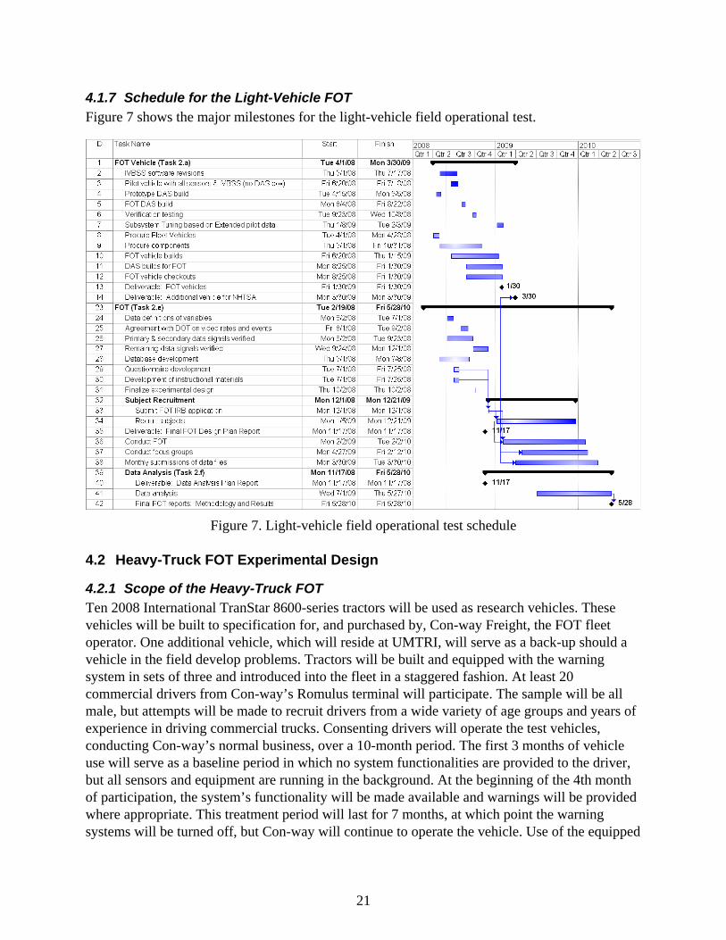
4.1.7 Schedule for the Light-Vehicle FOT Figure 7 shows the major milestones for the light-vehicle field operational test.
Figure 7. Light-vehicle field operational test schedule
4.2 Heavy-Truck FOT Experimental Design
4.2.1 Scope of the Heavy-Truck FOT Ten 2008 International TranStar 8600-series tractors will be used as research vehicles. These vehicles will be built to specification for, and purchased by, Con-way Freight, the FOT fleet operator. One additional vehicle, which will reside at UMTRI, will serve as a back-up should a vehicle in the field develop problems. Tractors will be built and equipped with the warning system in sets of three and introduced into the fleet in a staggered fashion. At least 20 commercial drivers from Con-way’s Romulus terminal will participate. The sample will be all male, but attempts will be made to recruit drivers from a wide variety of age groups and years of experience in driving commercial trucks. Consenting drivers will operate the test vehicles, conducting Con-way’s normal business, over a 10-month period. The first 3 months of vehicle use will serve as a baseline period in which no system functionalities are provided to the driver, but all sensors and equipment are running in the background. At the beginning of the 4th month of participation, the system’s functionality will be made available and warnings will be provided where appropriate. This treatment period will last for 7 months, at which point the warning systems will be turned off, but Con-way will continue to operate the vehicle. Use of the equipped
21

tractors by anyone that has not received training from UMTRI staff will be strongly discouraged. Con-way drivers will be identified using either the logistics data from the fleet or by manually inspecting face video at the start and end of each trip. The relationship among tractor, trip, and driver ID will be shared with the independent evaluator. Generally speaking, however, drivers are assigned to trucks and stay with those trucks; only in instances where a driver is on sick leave or on vacation do the drivers change, and even then replacement drivers will often drive their own truck rather than that of the person normally assigned to the same route.
The proposed experimental design would achieve approximately 400 weeks’ — or 7.5 years’ — worth of driving data on the heavy truck platform (about two years’ worth of baseline driving and 5.5 years’ worth of driving data with the warning system activated). The FOT will be conducted over 10 contiguous months that include significant seasonal variations in weather and lighting conditions.
4.2.2 Characterization of the Heavy-Truck Fleet For the heavy-truck platform, the FOT will be conducted with the assistance and cooperation of the Con-way Freight Company. Con-way Freight is a regional and nationwide less-than-a-truckload (LTL) company that specializes in the transportation and delivery of palletized freight. Companywide, Con-way employs over 30,000 professional drivers, and operates over 32,000 power units (tractors) and approximately 80,000 trailers. In addition to Con-way’s willingness and commitment to participate in the FOT, the fleet also meets a number of other criteria necessary for a successful FOT. These include a willingness to purchase the tractors, logistical and operational constraints, personnel considerations, and proximity of the fleet to the other program partners.
Figure 8. Heavy truck used in the FOT
For the FOT, Con-way will operate tractors from its Romulus, Michigan, service and distribution center. At this terminal, Con-way operates approximately 80 tractors and 220 trailers in both line-haul1 and a local pick-up and delivery (P&D) operations. Preliminary exposure estimates show that 80 percent of the miles traveled by the FOT vehicles will be on limited-access roads,
1 A fixed-route system that moves freight between distribution terminals.
22

while the remaining 20 percent will be on major surface roads. Each FOT tractor will be assigned to a specific line-haul and P&D route. During the day, a tractor will be employed on a P&D route, while at night the same tractor will be used for a line-haul route. The drivers for these routes are bid out every year and are based on seniority. Con-way does not run a “slip-seat” operation; rather, drivers are assigned to tractors and aside from vacations and sick time (and any intentional rotation of tractors per the experimental design), the same drivers will be driving the same tractors on the same routes for the entire FOT. This has been confirmed by Con-way and is part of the agreement with UMTRI. Tractors will be in operation approximately 20 hours per day with two drivers assigned to each tractor. The overall total mileage for the fleet is expected to be around 700,000 miles, with 15,000 hour of driving.
There are exceptions, but in general Con-way uses sets of 28-foot trailers for all line-haul operations. For P&D, Con-way typically uses a 48-foot trailer but can also use 28-, 40-, 45-, and 53-foot trailers. P&D trailer selection is a function of route and time of year, as the freight business varies during the year.
4.2.3 Sampling Variables for the Heavy-Truck FOT Only drivers with valid CDLs and a minimum of two years experience in driving heavy-duty trucks will be included. Every attempt will be made to recruit a wide range of driver ages. However, gender cannot be balanced with the population of drivers at the Romulus terminal, as 99 percent of these drivers are male.
Con-way Freight has a very low turnover rate, so very little change in drivers is expected. The turnover rates at the Ann Arbor terminal (where the extended pilot testing will be conducted) are comparable to those at the Romulus terminal. Nonetheless, additional drivers, beyond those needed initially, will be trained so that any driver who could not complete the study could be easily replaced. Initially, 20 drivers will be recruited, which will allow for possible attrition.
4.2.4 Participant Recruitment for the Heavy-Truck FOT Ten FOT tractors will be based at Con-way’s Romulus terminal. Based at this facility are over 100 drivers, 43 line-haul tractors, 33 daily-delivery tractors, 217 28-foot line-haul trailers, and 71 daily-delivery trailers ranging in size from 42 to 53 feet.
The following is a breakdown of drivers by age group:
• Age 20 to 29 (12%) • Age 30 to 39: (28%) • Age 40 to 49 (37%); • Age 50 to 59 (19%); and • Age 60 and older (4%)
A notice will be posted at the terminal and at least one information session will be held to inform potentially interested drivers what participation in the FOT entails. If there are more interested drivers than are needed for the FOT, then drivers will be selected somewhat randomly. For example, all other factors being equal, a driver with more experience at Con-way Freight would be selected to participate in the FOT over a driver with less Con-way experience. The rationale for this decision is that it is important to reduce the likelihood of driver turnover in the FOT, and
23
while not a guarantee, it is assumed that a driver with more experience at Con-way would be less likely to leave the company in the middle of the FOT.
4.2.5 Participant Orientation and Instruction for the Heavy-Truck FOT Customized training will be necessary for drivers, mechanics, and fleet management personnel involved in this FOT. This training will be conducted in small groups or one-on-one sessions with UMTRI and FOT partners participating as appropriate. In previous FOT work, UMTRI has learned that frequent personal interaction and progress updates are important motivators for the drivers and mechanics at the fleet. In part, the success of the FOT relies on their input, so UMTRI will work actively to keep them involved in the ongoing FOT. Training is an important element toward this goal. To the extent possible, training will be integrated into the normal training procedures of the fleet, which serves two purposes. First, it ensures that the people in charge of the day-to-day fleet operation know the expectations placed upon the drivers and mechanics. Furthermore, their knowledge of the operation provides valuable input as to the most efficient way to get the work done. Second, fleet management personnel will need to become knowledgeable about the various system components involved in the study. Since most questions and problems will come first to these professionals, it is important that they have the necessary instruction and FOT contact information. In short, the supervisors need to be ready to play their front-line roles in the FOT.
Driver training will begin with an introduction to the research vehicles and how the warning system operates, with an opportunity to ask specific questions of a researcher. The introduction will concentrate on the usability aspects of the system, including video examples of circumstances in which drivers could expect to receive warnings. This will include an explanation about what each system does, how it works, and how to identify any operational problems. The experimental apparatus will be identified and their purposes explained. Drivers will be given FOT manuals that contain all the information covered in the training session along with contact information and samples of “driver event” forms. Copies of this material will also be kept in each of the FOT tractors for the duration of the study, including a logbook in which to make comments and emergency contact information. Drivers will also receive hands-on instruction in an equipped tractor. While accompanied by a researcher, each driver will experience the system first-hand during an orientation drive of at least 30 minutes on local roadways in normal traffic. The researcher who provides the orientation will thereafter be the primary point of contact for the driver should any questions or concerns arise.
4.2.6 Assisting Heavy-Truck Participants in the Field Each tractor will be equipped with a cellular telephone that could be used by drivers to contact researchers as necessary. A minimum of two researchers will carry pagers, having one common number, at all times during the FOT. Drivers are assured of contacting a researcher, if the need arises, on a 24-hour-a-day basis.
Every attempt will be made to not disrupt Con-way Freight’s business operations. In the event that an equipped tractor needs to be repaired, the tractor will be pulled from service and replaced with a fully functional tractor that UMTRI will maintain as a back-up. Once the repairs have been completed, the FOT tractor will be returned to the Con-way terminal.
24

4.2.7 Schedule for the Heavy-Truck FOT Figure 9 shows the major milestones for the heavy-truck field operational test.
Figure 9. Heavy-truck field operational test schedule
25

5 Objective Data Collection This section covers both numeric and video data that will constitute the FOT database for both light-vehicle and heavy-truck platforms. This data is objective in the sense that it is undistorted by emotion or personal bias and is based on observable evidence.
5.1 The Objective Dataset The primary goal of the FOT is to determine whether an integrated safety system brings about objectively measurable changes in driver performance parameters that are likely to affect heavy-truck and light-vehicle crash rates. The bulk of the data necessary to answer this question will be provided by a purpose-built data acquisition system that will be virtually transparent to the drivers on both platforms and have minimal impact on Con-way operations in general. In addition to data collected by the DAS, supplemental objective data will be taken from a variety of sources including existing road attribute databases, Con-way’s logistical archive, and the National Weather Service (for examples of the data collected from the fleet, see Section 5.9.5). There will be extensive subjective data collected using driver questionnaires, focus groups, and driver interviews. This section characterizes the objective data that will be collected and stored in a relational database structure.
The DAS on both platforms will collect hundreds of signals of data along with substantial video of the scene around the vehicle and within the driver cabin environment. On a broad level, these measures are characterized in Table 4. Although this is not an exhaustive channel data list, it covers the general categories of data retrieval and shows within each category the type of data that will be collected to characterize and archive how the system performed, the activities of the driver, and the environment and state of the vehicle. For both platforms, the general configuration of the DAS is the same, but there will be some minor differences associated with the data retrieval mechanism, storage capacity, sampling rates, and data stored. In addition to collecting these measures, a substantive quality control process will be used to ensure data channel accuracy. This process is described in Section 9.2, Data Validation. Table 4 shows general data categories as a function of four classifications, defined as:
• Source: Most data collected by the DAS will be from a dedicated CAN bus (or set of CAN buses) implemented, programmed, and structured specifically for this project. Specific details of this CAN implementation can be found in the Light- and Heavy-Vehicle Interface Control Documents. However, other data will come from the original equipment vehicle bus (engine and body on light vehicle and J1939 on heavy truck). UMTRI will install its own set of sensors on both platforms. These sensors will provide researchers at UMTRI with additional measures of vehicle and driver performance, which are independent of the warning system. Finally, a category classified as other includes objective data that will be linked to the onboard DAS data but will be culled from external data sources such as the National Weather Service, the Highway Performance Monitoring System, and Con-way’s logistical databases, for example.
• DAS Format: How these data are stored falls into five general types:
o Custom: Specifically this category applies to the radar and video cameras. For all radar units, the DAS will record all radar targets and their associated data with the
26

exception of the forward radar on the heavy-truck platform. In this case the signals for the primary forward target will be recorded at 10 Hz while the signals for up to six secondary targets will be recorded at 2 Hz. Video on both platforms will be recorded at the highest frequency possible given the storage and compression considerations for the DAS. All video measures will also be triggered at least 10 Hz with a pre- and post-event window to capture and save the visual content of the scene surrounding a warning.
o 10 Hz Series: Most objective data from the vehicle will be saved in a time-history format with a 10 Hz resolution.
o Triggered Event: Many objective data signals will be event-logged by the DAS. That is, when a signal transitions beyond a threshold or there is a warning, the start and end time of that event will be saved along with other relevant signals. These triggered events are the building blocks of more complex analysis methodologies that are used to address specific questions related to how the system and vehicle performed and, more critically, how the driver might have changed their driving behavior. Also, since these summaries are relatively small in size, they can be downloaded to UMTRI after each trip and used to monitor the health of the system and the experience of the driver.
o Transitional: Logged events contain the same content as time history events, but require less space and are often easier to summarize in large datasets.
o Aggregated: This general classification nearly always involves performing some type of operation on a specific signal, and results in a number or set of numbers that reflect an overall summary of the measure. Examples include distance traveled, which is the integration of the speed signal over the time resolution of that signal, and the count of brake applications by the driver. Another important aggregation is histograms or the categorization of a signal into predefined bins to produce a time-weighted distribution of a signal. In some cases, two-dimensional histograms are created showing the relationship between two signals such as road type and speed.
• Platform: Gives an indication of the differences between the objective data archive of each of the platforms as well as, more importantly, their similarities.
• To Monitor: Gives a general breakdown of what the objective data measure will be used for. In many cases, the individual measures will serve in multiple analysis approaches to better understand the driver, environment, warning system, or vehicle performance.
27

Table 4. DAS data collection variables
Data Category
Source DAS Format Platform To Monitor
Vehi
cle B
us
Sys
tem
Bus
(s)
UMT
RI (A
toD)
Oth
er
Cust
om
10 H
z ser
ies
Trig
gere
d Ev
ent
Tra
nsiti
onal
Agg
rega
ted
Heav
y Tru
ck
Lig
ht V
ehicl
e
Drive
r Act
ivity
Envir
onm
ent
IVBS
S
Vehi
cle
Radar Front x x x x x x x Side x x x x x x x Rear x x x x x
Lane-Departure Boundary types x x x x x x Lane position x x x x x x Lateral speed x x x x x x Lane change events x x x x x x x Ambient light x x x x x x Future lane offset x x x x x x Road shoulder width x x x x x x Road curvature x x x x x x Alert request x x x x x x x x Status x x x x x x x
Lane-Change/Merge Lateral presence x x x x x x x Lateral clearance x x x x x x x Future lateral clearance x x x x x x Time to lane crossing x x x x x x Object position x x x x x x Object velocity x x x x x x Alert request x x x x x x x Status x x x x x x x
Forward Collision Heading wrt road x x x x x x CIPV Range x x x x x x x CIPV Range rate x x x x x x x CIPV Azimuth x x x x x x x CIPV Ax x x x x x x x Target type x x x x x Lane change flag x x x x x x Alert request x x x x x x x Status x x x x x x x
Curve Speed Warning Map type x x x x x Mapping quality x x x x x Availability x x x x x
28

Source DAS Format Platform To Monitor
Data Category
Maximum desired speed x x x x x Required acceleration x x x x x Most likely path x x x x Number of thru lanes x x x x x Road curvature points (CPOI) x x x x x Alert request x x x x x x Status x x x x x x
DVI Display state x x x x x x System sensitivity x x x x x x x System suppression x x x x x x x x x Visual alert x x x x x x Audio alert x x x x x x Haptic alert x x x x x Alertness index x x x x x x Status x x x x x x x
Vehicle Performance Transmission speed x x x x x x Transmission gear x x x x x Fuel Used x x x x x Engine torque x x x x x Retarder torque x x x x x Coolant temp x x x x Intake temp x x x x Battery voltage x x x x x x x Traction control x x x x x x x ABS event x x x x x x Status x x x x x x x
Driver Activity and switches Wipers x x x x x x x Turn signal x x x x x x x Steer x x x x x x x Accel. pedal x x x x x x Brake x x x x x x x Head/parking lamp x x x x x x Horn x x x x Cruise control x x x x x x Parking brake x x x x Clutch state x x x x x
Vehi
cle B
us
Sys
tem
Bus
(s)
UMT
RI (A
toD)
Oth
er
Cust
om
10 H
z ser
ies
Trig
gere
d Ev
ent
Tra
nsiti
onal
Agg
rega
ted
Heav
y Tru
ck
Lig
ht V
ehicl
e
Drive
r Act
ivity
Envir
onm
ent
IVBS
S
Vehi
cle
29

Data Category
Source DAS Format Platform To Monitor
Vehi
cle B
us
Sys
tem
Bus
(s)
UMT
RI (A
toD)
Oth
er
Cust
om
10 H
z ser
ies
Trig
gere
d Ev
ent
Tra
nsiti
onal
Agg
rega
ted
Heav
y Tru
ck
Lig
ht V
ehicl
e
Drive
r Act
ivity
Envir
onm
ent
IVBS
S
Vehi
cle
Vehicle State Measures Weight x x x x x Ax x x x x x x Ay x x x x x x Yaw rate x x x x x x x Speed x x x x x x x Roll angle x x x x x x Roll rate x x x x x x Lat. and Long. x x x x x x x Compass heading x x x x x x x
System State and Diagnostic Versions x x x x x Heartbeats x x x x x Failure codes x x x x x x Histograms x x x x x Enabled x x x x x
Road Characteristics Limited access x x x x x Ramp x x x x x Major surface x x x x x Minor surface x x x x x Local x x x x x AADT x x x x x Number of thru lanes x x x x Urban flag x x x x x Paved flag x x x x x Function class x x x x x x
Time of Day Solar zenith angle x x x x x x
Traffic Number of targets x x x x x x Location of targets x x x x x x Estimated traffic density x x x x x
Trip Summary Statistics Distance traveled x x x x x Counts of events x x x x x System availability time x x x x x Vehicle location x x x x x Vehicle ID x x x x
30

Data Category
Source DAS Format Platform To Monitor
Vehi
cle B
us
Sys
tem
Bus
(s)
UMT
RI (A
toD)
Oth
er
Cust
om
10 H
z ser
ies
Trig
gere
d Ev
ent
Tra
nsiti
onal
Agg
rega
ted
Heav
y Tru
ck
Lig
ht V
ehicl
e
Drive
r Act
ivity
Envir
onm
ent
IVBS
S
Vehi
cle
Weather Precipitation x x x x x Wind speed x x x x Wind direction x x x x Temperature x x x x x Visibility x x x x Atm pressure x x x x
Video Forward x x x x x x Left side x x x x x x Right side x x x x x x Cabin x x x x x x x Face x x x x x x x
Driver Characteristics Age x x x x x Gender x x x x x
5.2 Light-Vehicle and Heavy-Truck Dedicated Instrumentation In addition to the measures from the warning system and the vehicle CAN, UMTRI will instrument each platform with a complement set of sensors that will support and provide additional signals for the analysis phase of the project. These instruments are not part of the system and will be installed to provide an independent measure of critical metrics both for the analysis and confirmation of system and vehicle performance. For both platforms, the additional sensors will include the following:
• DGPS: UMTRI’s own differentially corrected GPS module and associated antenna. Measures from this device include latitude, longitude, heading, speed, time and week, number of satellites, and Pdop (percent dilution of position, which is measure of the geometrical strength of the GPS satellite configuration).
• Yaw Rate: A stand-alone yaw rate sensor to measure angular velocity. The sensor is ruggedized for transportation applications and has a -60 to 60 deg/s resolution. A routine in the DAS software will zero the transducer each time the vehicle stops for at least 60 seconds.
• Accelerations: A bi- or tri-axial high-precision accelerometer will be used to measure at least longitudinal and lateral accelerations. The unit will be mounted near the lateral and longitudinal vehicle mid-point and as close to the vertical center-of-gravity as possible on light-vehicle. On the heavy truck, UMTRI will position the unit on the unsprung mass if
31

possible, ideally on the front axle; however, if this is not feasible, then on a rigid cross-member of the frame rail.
• Steer Angle: For light vehicles, steer angle is available via the engine control bus. For heavy trucks, UMTRI hopes to have ITE install a unit during production that is either part of a stability control package offered by a supplier (stability control devices are not normally part of the Con-way tractor specification and in these tractors any active control by this subsystem would be disabled). However, if this is not feasible, UMTRI would explore installing a customized steer-angle transducer as part of the DAS installation processes.
5.3 Camera Positioning for Video Collection All FOT vehicles on both platforms will be instrumented with five cameras to capture images of the driving scene and driver activity. The exact placement of the cameras on each platform is currently under review; however, UMTRI will capture the following: (a) the forward scene; (b) rearward directed left- and right-side scenes; (c) the driver’s face; and (d) the driver’s hands via a cabin-mounted camera directed over the driver’s right shoulder. Sample snapshots of these views are shown in Figure 10 through Figure 12.
The major reasons for capturing the video data are to:
• Understand circumstances associated with individual episodes, including the forward scene roadway, environment, and traffic, as well as the driver’s general direction of gaze;
• Provide samples of roadway type, environment, traffic, and driver behavior at periodic intervals; and
• Aid in determining certain “truth” variables through calculations based on manually assisted extracting of data from images.
The specifications of the five cameras on each platform are still being analyzed with selection criteria that include: field of view, vertical and horizontal resolution, minimum illumination, packaging and mounting considerations, and self-illumination (infrared) for images at night or in darkness. Currently, all cameras will be black-and-white CCD imagers with an analog output (RS170), with the exception of the forward camera, which is shared with the LDW system. For each of the cameras, the images captured by the DAS involve sub-sampling the original image.
Figure 10. Sample cabin and driver face images
32

Figure 11. Sample forward image
Figure 12. Sample left-side rear-looking image
5.4 Video Data Compression and Sampling Rates As with previous FOTs, the video archive consumes large amounts of memory and is estimated to be approximately 80 percent of the total FOT data volume. For this FOT, all video data will be compressed both spatially and temporally using H.264 (MPEG-4) video compression.
Video data is likely to be collected using frame rates that vary between two or three discrete frame rate values, depending on the circumstances. Images from the cameras may also be sampled at different rates during the same time period. Without direct experience with the crash warning functionalities, the tentative plan is to collect video from each camera in two distinct modes. The first mode is referred to as an exposure mode with a constant frame rate per second. The frame capture rate for the exposure mode will vary by camera and be between 1 and 10 Hz. The second mode is a triggered or episodic mode. In this mode, warning- and driver-related events will trigger a higher-rate episode to be captured, which has both a pre- and post-view window surrounding the triggering event. The collection rate of episodes will be at least 10 Hz.
5.5 Audio Data Collection Audio data will be collected using triggers that include those used for video. The time duration of audio data collection is not established; experience on another FOT project will prove useful.
33
Tentatively, audio might be collected for 10 sec around the time of these triggers. The purpose is to hear any audio tones. In addition, audio will be collected for 20 sec following a driver’s comment button press. Again, this time may be adjusted based on experience gained before the launch of the FOT.
Audio data is collected using circular buffers, as is video. With audio, however, the buffers consist of 0.5-second-long chunks of audio data, so that the time at which audio data capture begins is “quantized” by 0.5 second. The data itself will be collected at 8 KHz (tentative), with one byte of resolution. The format of this file is not determined, but it is not likely to be a standard Windows desktop format (e.g., WAV file), and will require some simple software to replay. Again, the tradeoff is multiplying the amount of data coverage at the cost of a few dozen lines of computer code to view or hear the data.
5.6 Data Acquisition System UMTRI will design and fabricate a data acquisition system for each vehicle on both platforms of the FOT. It will be installed in each vehicle as a complement to the system and function as both a data-processing device as well as permanent recorder of the objective and video data collected during the field tests. The sections below describe the design and operation of the DAS.
5.6.1 DAS Main Module DAS packages are being designed and constructed to meet the test requirements of the FOT and physical configuration of the FOT vehicles. Figure 13 shows the unfolded light-vehicle prototype DAS. The heavy-truck DAS will be same except for a different arrangement of the external connectors to accommodate the integration of the DAS in the truck. The package consists of four subsystems comprising a main computer, video computer, power controller, and cellular communications unit.
The main computer consists of an EBX form-factor single-board computer (including display, and Ethernet controllers), two PC104-plus CAN controller cards, a PC104 analog and digital interface card, and an automotive hard disk. All of these components operate over a –30C to +85C temperature range.
The video computer consists on an EBX form-factor single-board computer (including display, audio, and Ethernet controllers), two PC104-plus Mpeg4 encoder cards, a digital interface card, and an automotive hard disk. The temperature range of this system also operates from –30C to +85C.
The computers are configured to permit headless operation while a subject has the vehicle and hot-pluggable keyboard, mouse, and video operation for maintenance and troubleshooting activities. Figure 14 shows the location of the connectors for use in data upload and maintenance. The two computers are normally connected to each other via a crossover cable between the two network connectors. During upload this cable is removed and the two computers are plugged into a building Ethernet switch. A battery charger, on-off switch, and mode select switch plug into the mode connector.
34

Power Controller Video MainComputer Card Computer
Micro Controller
Signal Automotive Conditioning Cell Modem GPS Disk Drives Battery
Figure 13. Major light-vehicle DAS components
35

Gps and Cell Ethernet Status/LEDs Mode Inputs Modem Antennas
Power Camera Inputs CAN Analog Sensors USB andVideo
Figure 14. DAS, vehicle, and user interface
5.6.2 Modes of System Operation The system can operate in one of eight modes: FOT, Characterization, Demo, GUI, Maintenance, Upload, No CPU, and Toggle. Figure 15 shows the mode control box that is currently in use. It consists of a rotary mode switch and a toggle power switch. These switches, along with a battery charger, are connected to the DAS via the mode connector. If nothing is plugged into the mode connector (normal FOT operation) or if the mode control box is plugged in and the rotary switch is in the “FOT” position, the ignition signal controls the power sequencing and the system runs in the unattended FOT mode. Otherwise the toggle switch powers the computers (the rest of the vehicle remains off), and the computers run the appropriate programs. The DAS mode box also has a shroud (which is not obvious in Figure 15) to prevent accidental movement of the toggle switch. The following sections describe the operational modes of the DAS.
36

Figure 15. DAS mode control box
5.6.2.1 FOT DAS Mode The FOT software will be configured to organize all of the gathered data by trip. The main system decodes the CAN messages and extracts the appropriate signals, and scales and converts the data as necessary. Derived channels are then calculated and selected information is logged to a time-history file. The system is capable of logging raw CAN messages to a separate file for debugging purposes. Slowly changing or intermittent channels are logged transitionally. That is, a transition log is created, capturing transition events by their channel identification, timestamp, and data values.
An episode-processing task will monitor the incoming primary and calculated channels for the occurrence of significant episodes (e.g., collision warnings, lane departures, etc.). When an episode is detected, the main system logs details of the alert in a triggered-summary file, and sends a message via Ethernet to the video system. The video system then captures a retrospective clip of audio data extending some time period back from the moment of the episode transition. Transition counts, histograms, errors, and other trip summary information will be recorded to a trip log at the end of each trip. When a trip ends, the main system activates the cellular system to transfer data via modem to UMTRI. Once the transfer is complete, all systems are turned off.
The audio/video system continuously digitizes, encodes, and buffers the output of five video cameras and one microphone. When an episode trigger is received from the main system, the audio is saved to disk (video is saved continuously).
5.6.2.2 Upload Mode When the mode switch is in the “Upload” position, both computers will automatically transfer the files (of the returning driver) to their respective servers. The main computer maintains a catalog (in an Access database) of all data files generated for each trip. The upload program replicates the catalog to an SQL Server database, copies the files to a specific folder on the data server, and initiates the loading of data from files into tables in the database. The video computer logs onto the video server, uploads video catalog, and transfers the video files.
5.6.2.3 GUI DAS Mode This mode is an enhanced version of the FOT DAS that includes real-time display capability for any of the data channels defined in the project. This mode will be used for DAS validation, on-
37

track testing and system troubleshooting. LCD panels (powered by their own DC-DC converters) will be plugged into the VGA connectors on the interface panel. Almost all the data on the CAN bus will be parsed, scaled, and available for display. The video system will show the images from both cameras on the screen enabling real-time feedback for camera adjustments. Figure 16 shows the vehicle page of the light-vehicle GUI DAS.
Figure 16. Vehicle page of the light-vehicle GUI DAS
5.6.2.4 Characterization and Demo Modes These modes will be used during characterization-checkout experiments between drivers and for the driver training and demonstration trip. Data will be logged as in the FOT, but labeled and stored separately from the FOT data archive. Starting the computers by the toggle switch will cause the “System Enable” relay to be switched to the “system on” state.
5.6.2.5 Maintenance Mode In maintenance mode, the computers will be connected to the building Ethernet (or a laptop if necessary in the field) and will run file-sharing (server) services. This will permit changing of software, configuring project databases, driver setup, and file management from a host PC.
5.6.2.6 No CPU and Toggle Modes If the mode is set to “No CPU,” only the microcontroller is powered when the ignition switch is engaged. This setting is used when the vehicle is sent to the dealer for repair or maintenance. The
38

“Toggle” mode toggles the system-enable relay on and off. This allows a researcher to manually enable or disable system functionality as presented to the driver.
5.7 DAS Remote Monitoring To monitor the functionality of the DAS and warning system, UMTRI will customize the DAS Software to compute and report summary statistics that help flag and identify problems and failures with the system and the DAS itself. For example, specialized routines will compute the distance between the last and first GPS coordinates from sequential trips in order to determine if mileage (and therefore DAS trips) is missing from the data archive. Additionally, UMTRI will download and scrutinize the event logs from the DAS to look for unexpected operating system events from the main and video CPU modules in each DAS. The results of these efforts will then be loaded into a database and linked to specialized web pages to display functional and operational information to the program partners using a Web browser. On light-vehicle these summary and diagnostic numbers will be downloaded using an on-board cell modem to an UMTRI server following each ignition cycle. Heavy-truck the data will be automatically downloaded to UMTRI, either through a wireless area network at the fleet distribution terminal in Romulus or by using a cell modem approach similar to the light-vehicle platform. With both platforms the approach is to provide current summary and diagnostic information for engineers to remotely monitor the fleet on both platforms on a continuous basis throughout the entire FOT. Figure 17 shows a sample of the Web interface from the RDCW project.
Figure 17. Web interface for RDCW
39

5.8 DAS Data Retrieval Data will be retrieved from the DAS on a regular basis for both platforms. As in past UMTRI FOTs, comprehensive routines and protocols will be used to ensure that all DAS recorded data has been copied, loaded into a database, and backed up before being deleted from the DAS itself. The approach for data retrieval is platform dependent and outlined in the sections below.
5.8.1 Light-Vehicle Data Retrieval Data retrieval for the light-vehicle platform will occur when the subjects return their vehicles to UMTRI at the conclusion of the testing period. Upon arriving at UMTRI, the subjects will be asked to complete some post-FOT questionnaires while the vehicle or DAS is being connected to the UMTRI intra-net for the post-FOT driving scenario interview, in which a researcher presents the subject with detailed views of their driving experience while asking them questions related to their experience with the system. Following the interview, the contents of both the video and main computers on the DAS will be uploaded to computer servers for loading into the FOT database and file backup.
5.8.2 Heavy-Truck Data Retrieval Data retrieval for heavy-truck will occur using one of two methods. The first and preferred method is to install a wireless area network and a server at the Con-way Romulus facility, which is shown in Figure 18. This server and network would be operational at all times and when the tractors are parked (ignition off) at the terminal, as determined by GPS (a component of the DAS), the DAS would initiate the network services and begin a download procedure moving all recently collected files to a server within the Con-way facility. Then following the download process, the DAS would automatically be given a list of files to delete before performing an automatic shutdown. In no event would the DAS remain operational for more than 10 minutes following an ignition off event to avoid the possibility of discharging the tractor batteries. A dedicated virtual-private-network would be established between the servers at UMTRI and Con-way and procedures periodically would copy any recent files from the Con-way server to UMTRI servers. Then procedures on the UMTRI servers would load the project database, back-up the data, and provide a list of files to delete to the Con-way server for the next connection by a given DAS.
40

Re-distribution
Center
Re-distribution
Center
Maintenance Facility
MaintenanceFacility
Tractor Parking TractorParking
Figure 18. Plan-view of the Con-way facility at Romulus, Michigan
The second data retrieval method for heavy-trucks will be used if the volume of data collected by the DAS—initial estimates are in the range of 250 to 500 MB per hour for both video and objective data—is beyond the capacity of a current wireless area network given the allowable time for the download to occur. That is, since the video files will be significant, there is a distinct possibility that a typical download cannot finish within allowable time window. In such an event, UMTRI will coordinate a manual data retrieval process that involves visiting each FOT tractor in the fleet on a normal basis to download data and manage the available space on each DAS. The frequency of these visits would be function of file and DAS disk-drive size. For data and system quality monitoring, UMTRI will use the on-board cell modem approach similar to light-vehicle to monitor the health of the fleet. Data from the fleet would then be uploaded into the appropriate database and backed-up for archiving.
During the extended pilot test, only the manual retrieval method will be employed, while both methods of data retrieval will be used in the FOT.
5.9 External Data Sources
5.9.1 Digital Maps The light-vehicle fleet has chosen the NavTeq digital road map. The data signals associated with the onboard digital road can be found in section 7.A.i. The availability of these maps is
41
determined by the contract Visteon has with NavTeq. The project will provide access to Volpe for whatever NavTeq digital data is necessary. This access will be similar to that provided in the RDCW FOT project. The heavy-truck fleet will not be using an onboard digital map.
5.9.2 GIS Data The project anticipates using a variety of spatial database resources, including the Highway Performance Monitoring System data for Michigan roads. The project will also use spatially calibrated aerial photos and a digital base map for southeast Michigan, both generated by the Michigan Center for Geographic Information. In addition, the traffic control inventories for Washtenaw and Oakland counties and the signalized intersections inventory for southeast Michigan are also available.
5.9.3 Crash History Data The project has access to more than 10 years of Michigan Office of Highway Safety Planning crash data. The crash data fields include time of day, weather, driver, vehicle, and crash type information; and geographic location of the crash.
The project anticipates using two to five years of crash data to determine the clusters of crash types addressed by the program. The location of crash clusters addressed by system technologies will be determined using spatial statistical tools. These tools determine clusters of crashes that are statistically significant based on their location.
The project also anticipates developing spatially significant clusters of system warning alerts. The clusters of alert and crash history will be analyzed to help determine the predictive quality of the warning systems relative to actual crash patterns.
5.9.4 National Radar Weather Data UMTRI has been engaged for some time in conversations with the Weather Systems and Assessment Program, Research Applications Laboratory of the National Center for Atmospheric Research in Boulder, Colorado. The preliminary plan is to post-process radar data that are obtained from the National Climatic Data Center with the assistance of NCAR. NCAR processes code that will allow UMTRI to calculate active precipitation from the radar data using GPS time and location information recorded onboard the vehicles. This data can then be stored in a separate table in the FOT database and used in conjunction with windshield wiper state from the vehicle data to determine any potential influence that active precipitation has on driver behavior, particularly driver reaction time to warnings.
5.9.5 Con-way Delivery Logs To supplement the data collected onboard equipped tractors, UMTRI is currently working with Con-way to determine which of the following logistical data are available for electronic download from the fleet versus which are not electronic and therefore will have to be provided manually (driver activities, freight hauled, customers visited, driver, equipment used during the FOT and, more specifically, for a given tour or segment of a driver’s day). Since Con-way drivers do not use a fleet-based monitoring system to record their driver activities, UMTRI will rely on this logistics information for a number of critical associations in the FOT database (most importantly the association between data collected on a specific tractor on a given trip and the driver making the delivery). Since Con-way runs a quasi-slip-seat operation (i.e., there will be
42

more than one driver for each of the FOT tractors), UMTRI cannot rely on a simple scheme of assigning drivers to tractors to make this critical association.
UMTRI will also use logistics information for estimating the total vehicle weight and configuration. A database of Con-way equipment specifications will allow UMTRI to track and classify the different vehicle configurations that the fleet runs. Generally, these are double-trailer combinations for their line-haul operations and single-trailer combinations in their pick-up and delivery routes; however, there are variations and this distinction will be important to fully understand system and driver performance issues. Drivers will input the trailer configuration via the DVI. Post-trip analysis of the MACOM radar may be used to verify the driver selection along with a quick review of the rear-looking video data. Tractor-trailer configuration will be part of the dataset. Regarding total vehicle weight, UMTRI will aggregate estimated pallet weight that is tracked by the Con-way logistics system. These data, along with an estimated weight value derived using tractor drive train performance measures (engine torque and speed, gear and vehicle speed), will provide insight into how driver and vehicle performance may vary as a function of the gross vehicle weight, which has already been shown to have a measurable effect on driver behavior.
The processes to retrieve logistical data will be tested in the extended pilot test. Additionally, vehicle maintenance information will be requested from Con-way.
5.10 Participant Descriptors and Assessments UMTRI is currently engaged in the S05 Task 5 (Driver Assessment Plans) for the SHRP-2 Field Study. As part of this task, UMTRI has participated in the identification of numerous instruments that could be used in assessing, or describing, driver characteristics and capabilities. The goal on the S05 Task 5 was to develop an assessment program that could reasonably be applied to all participant age groups, and do so within a two-hour period.
However, in the IVBSS FOT, there will be only about 10 to 15 minutes to conduct assessments with the participants, and a limited amount of time to have the participants complete certain instruments at home, prior to arrival. As such, this program cannot attempt to replicate all of the assessments and descriptors being undertaken on the SHRP-2 program, desirable as it might be. Instead, a subset of the tools being proposed for use in SHRP-2 is proposed (see Table 5); in addition, it will be determined whether the item will be completed in-person or by the participant at home. All instruments will be administered to drivers on both platforms, but the content of the driving knowledge questionnaire will vary between platforms, with the heavy-truck drivers receiving questions that are pertinent to commercial driving requirements.
43

Table 5. Driver assessment and descriptor summary
Measurement Construct Description In-Person / At home
Est. Time (minutes)
Risk-Taking Behavior Cox Assessment of Risk Driving Scale
At home 2
Risk Perception CARDS items combined with DeJoy Risk Perception Questionnaire
At home 2
Driver Behavior Manchester Driver Behavior Questionnaire
At home 5
Driver Style Manchester Driver Style Questionnaire
At home 5
Thrill/Adventure Seeking Sensation Seeking Scale At home 5 Driving Knowledge Custom questionnaire based on
state licensing tests In-person 10
5.10.1 Driver Biographical Information Driver biographical information that will be collected includes age, gender, ZIP code, estimated income, highest level of education completed, occupation, and the make, model, and year of a participant’s primary and secondary vehicles. Some of this information will already be known from the participant’s driving record, while the drivers themselves provided other data. Additional information that will be self-reported includes years or driving experience, miles driven annually, whether the participant smokes, and whether the participant wears eyeglasses or contact lenses.
5.10.2 Michigan Driving Records Michigan driving records (a listing of police-reported crashes, moving violations, and motor vehicle-related convictions) will be obtained for each participant in both the light- and heavy-truck field tests. UMTRI is now a repository of these driving records, receiving biannual updates from Michigan. As such, once approval to use the records on the IVBSS program is obtained, it will be possible to obtain relatively current versions of a participant’s driving record.
44


DOT HS 811 010 August 2008