Integrated Ship Defense - Applied Physics Laboratory · Integrated Ship Defense ... Documentation...
13
JOHNS HOPKINS APL TECHNICAL DIGEST, VOLUME 22, NUMBER 4 (2001) 523 T Integrated Ship Defense Richard J. Prengaman, Edward C. Wetzlar, and Robert J. Bailey he Laboratory has been instrumental in developing a new series of combat systems based on integrated ship defense concepts. These Ship Self-Defense Systems are being installed on Navy aircraft carriers and major amphibious ship classes to meet stringent performance requirements for ship defense against highly capable Anti-Ship Cruise Mis- siles. Derived requirements for achieving the requisite probability of raid annihilation P RA have led to the compelling argument that integrated ship defense systems must have open, distributed architecture designs. This architecture enables a powerful composite approach to self-defense at both weapon and sensor levels and is a realistic approach to meeting difficult P RA requirements. INTRODUCTION The development of an integrated ship self-defense concept has been under way for 15 years, beginning in November 1986, when the Secretary of Defense invited NATO nations to work with the U.S. Navy to develop a ship self-defense capability. From 1987 to 1991, engi- neers from Canada, Germany, the Netherlands, Spain, and the United Kingdom worked with U.S. engineers and several international consortia to develop require- ments and test ship self-defense concepts. The objective was to perform engineering studies and critical experi- ments leading to a system concept and specification for system acquisition. All aspects for a new combat system were studied. Tests were performed to verify missile control concepts (thrust vector control), information distribution over a local area network (LAN; “infor- mation highway”), and sensor integration and control concepts. The NATO Anti-Air Warfare (AAW) System (NAAWS) studies proposed a distributed archi- tecture (LAN) combat system based on solid-state phased array radars integrated with passive infrared and electronic support measures (ESM) sensors and a highly agile short-range missile operating under automated rules of engagement defined by doctrine. Although NAAWS did not result in an interna- tional development program, the requirements and con- cepts formed the basis for a U.S. Navy Quick Reaction Combat Capability (QRCC) demonstration program initiated in 1991. The objective of this self-defense program was to integrate existing and planned detec- tion and engagement systems with a control element to provide an automated, quick-response, multitarget engagement capability against closing air targets. The NAAWS participating countries used the results of the NAAWS program to develop the combat systems and components presented in Table 1. Staff from APL, Naval Surface Warfare Centers (Dahlgren and Port Hueneme), and Hughes Aircraft developed the QRCC Demonstration System (Fig. 1),
Transcript of Integrated Ship Defense - Applied Physics Laboratory · Integrated Ship Defense ... Documentation...

JOHNS HOPKINS APL TECHNICAL DIGEST, VOLUME 22, NUMBER 4 (2001) 523
INTEGRATED SHIP DEFENSE
T
Integrated Ship Defense
Richard J. Prengaman, Edward C. Wetzlar, and Robert J. Bailey
he Laboratory has been instrumental in developing a new series of combat systems based on integrated ship defense concepts. These Ship Self-Defense Systems are being installed on Navy aircraft carriers and major amphibious ship classes to meet stringent performance requirements for ship defense against highly capable Anti-Ship Cruise Mis-siles. Derived requirements for achieving the requisite probability of raid annihilation PRA have led to the compelling argument that integrated ship defense systems must have open, distributed architecture designs. This architecture enables a powerful composite approach to self-defense at both weapon and sensor levels and is a realistic approach to meeting difficult PRA requirements.
INTRODUCTIONThe development of an integrated ship self-defense
concept has been under way for 15 years, beginning in November 1986, when the Secretary of Defense invited NATO nations to work with the U.S. Navy to develop a ship self-defense capability. From 1987 to 1991, engi-neers from Canada, Germany, the Netherlands, Spain, and the United Kingdom worked with U.S. engineers and several international consortia to develop require-ments and test ship self-defense concepts. The objective was to perform engineering studies and critical experi-ments leading to a system concept and specification for system acquisition. All aspects for a new combat system were studied. Tests were performed to verify missile control concepts (thrust vector control), information distribution over a local area network (LAN; “infor-mation highway”), and sensor integration and control concepts. The NATO Anti-Air Warfare (AAW) System (NAAWS) studies proposed a distributed archi-tecture (LAN) combat system based on solid-state
phased array radars integrated with passive infrared and electronic support measures (ESM) sensors and a highly agile short-range missile operating under automated rules of engagement defined by doctrine.
Although NAAWS did not result in an interna-tional development program, the requirements and con-cepts formed the basis for a U.S. Navy Quick Reaction Combat Capability (QRCC) demonstration program initiated in 1991. The objective of this self-defense program was to integrate existing and planned detec-tion and engagement systems with a control element to provide an automated, quick-response, multitarget engagement capability against closing air targets. The NAAWS participating countries used the results of the NAAWS program to develop the combat systems and components presented in Table 1.
Staff from APL, Naval Surface Warfare Centers (Dahlgren and Port Hueneme), and Hughes Aircraft developed the QRCC Demonstration System (Fig. 1),

524 JOHNS HOPKINS APL TECHNICAL DIGEST, VOLUME 22, NUMBER 4 (2001)
R. J. PRENGAMAN, E. C. WETZLAR, and R. J. BAILEY
which was successfully tested in June 1993 aboard USS Whidbey Island (LSD 41) on the test range at the Atlantic Fleet Weapons Test Facility. Using an APL-developed LAN-based communications infra-structure, the demonstration proved that measurements from the various sensors (AN/SPS-49 radar, Phalanx Close-In Weapon System [CIWS] search and track radars, AN/SLQ-32 ESM System, and AN/SAR-8 Infra-red Search and Track [IRST] System) could be combined to develop a single coherent track picture and be inte-grated with engagement systems (RAM and CIWS gun) to provide a doctrine-controlled combat system. This system would later be designated the Ship Self-Defense System (SSDS) Mk 1.
In August 1993, work began to provide a production SSDS Mk 1 for the LSD 41/49 ship class. Although requirements for the demonstration system existed, a re-examination was conducted for the production system. APL spearheaded the flowdown of mission, perfor-mance, and operational requirements from high-level Navy documents and published the resulting overall QRCC system specification and a concept of operations document. The components of the QRCC were des-ignated as segments, and a segment specification was developed for the integration and control segment, i.e., the SSDS Mk 1. In developing the system and seg-ment specifications, APL led 21 engineering teams com-posed of 4 to 5 members, each with expertise in sensor
Figure 1. The QRCC Demonstration System successfully intercepted simulated Anti-Ship Cruise Missile threats during testing. This was the first demonstration of an open-architecture, LAN, distributed processing combat system.
Table 1. Combat systems and components resulting from the NAAWS program.
NAAWS team member Ship or combat system Sensor element Weapons elementUnited States Ship Self-Defense Advanced Integrated Electronic Rolling Airframe System (multiple ship Warfare System (AIEWS) Missile (RAM) classes) Multifunction radar (SPY-3) Evolved Seasparrow Volume search radar (VSR) Missile (ESSM)
Canada, The Netherlands, Netherlands and Infrared Search and Track System RAM, ESSMGermany German frigates (SIRIUS) Active phased array radar (APAR) Volume search radar (SMART.L)
United Kingdom Type 45 destroyer Active phased array radar Principal Anti-Air (SAMPSON) Missile System (PAAMS)
PhalanxCIWS
AN/SPS-49radar
AN/SLQ-32ESM
AN/SAR-8IRST
SensorSupervisorworkstation
WeaponsSupervisorworkstation
RAMsystem
Detect Control Engage
ECMUK-44
WSN-2
FDDI/SAFENET fiber-optic LAN
Ethernet, instrumentation LAN
Softwaremaintenance/
DX consolidationworkstation
Simulationcontrol
workstation
PhalanxCIWS

JOHNS HOPKINS APL TECHNICAL DIGEST, VOLUME 22, NUMBER 4 (2001) 525
INTEGRATED SHIP DEFENSE
integration, local command and control, weapons inte-gration, LAN/communications infrastructure, and the Human–Machine Interface (HMI) for operator con-soles. Software and hardware requirements were then developed that were traceable to the segment and system specifications.
A top-level design review held in December 1994 was followed by an intensive period of detailed design from January through September 1995. Instead of a single critical design review, a series of approximately 30 in-process detailed design reviews was conducted. This allowed for a more intensive examination of the design of each software component. Documentation for these reviews was then used in a final segment design document.
Testing of the SSDS Mk 1 was performed at Wal-lops Island, Virginia, and in USS Ashland (LSD 48) during 1996 and 1997, culminating in a successful at-sea technical evaluation (TECHEVAL) in April 1997 and operational evaluation (OPEVAL) in June 1997. USS Ashland commenced the first SSDS Mk 1 deployment on 3 October 1997 (Fig. 2). USS Mount Rushmore (LSD 47) completes installation of the SSDS Mk 1 in December 2001. This marks the completion of installations on all 12 ships of the LSD 41/49 ship class. USS Mount Rushmore will commence deploy-ment at the conclusion of Combat System Ship Quali-fication Testing in November 2002.
The SSDS Mk 1 was also installed on the Self-Defense Test Ship (SDTS), where it supported RAM Block 1 upgrade testing during 1998 and 1999 and cur-rently is supporting ESSM testing. The SSDS Mk 1 received Vice President Gore’s Hammer Award in Sep-tember 1998 for the short time and low cost in develop-ing such a successful combat system.
An evolved SSDS-based combat system is currently being developed that will improve the self-defense capa-bility against Anti-Ship Cruise Missiles (ASCMs) for aircraft carriers and a new class of amphibious assault
ships. This combat system marries the sensor integration and composite tracking capabilities of a new baseline Cooperative Engagement Capability (CEC) with a new SSDS Mk 2 being developed as a technology upgrade of SSDS Mk 1. The SSDS Mk 2 provides the LAN infrastructure, overall integration and control, and oper-ator display/HMI capabilities of the combat system, and integrates the electronic warfare system, the new Nulka decoy system, RAM Block I, and the upgraded NATO Seasparrow Surface Missile System (NSSMS), includ-ing its four tracker/illuminators. Improvements were made by APL staff to the Common Genealogy Archi-tecture Infrastructure for message distribution and the Common Display Kernel. These improvements were then transitioned to the industrial design agent. SSDS Mk 1 Motorola 68040 single-board computers were upgraded to Power PCs. SSDS Mk 1 software applicable to SSDS Mk 2 was transferred to operate on the Power PCs, and new functionality was added. The distributed open architecture eases the addition of the new combat system interfaces for the new ship classes.
SSDS Mk 2 is being developed in three versions. Mod 0 interfaces to the Advanced Combat Direction System (ACDS) Block 1 and the CEC, and will be deployed as an interim system on the USS Nimitz (CVN 68) aircraft carrier in June 2003. In addition to the self-defense capabilities of Mod 0, the final version of the SSDS Mk 2 will incorporate requisite combat system functions of the ACDS Block 1 such as tactical data link integration and air control. The version designated Mod 1 will be deployed on USS Ronald Reagan (CVN 76) in August 2004, with subsequent deployment on other CVN ships, and will be backfit to USS Nimitz in March 2004. The Mod 2 version will be deployed first on USS San Antonio (LPD 17) in 2005, then on subse-quent LPD ships. Mod 2 is a subset of the Mod 1 system. The CVN 76 combat system is illustrated in Fig. 3.
The SSDS Mk 2 is currently being considered for use on the LHD ship class. Organizational development
Figure 2. The SSDS Mk 1 was integrated into the Fleet beginning with the LSD 41/49 class (BFTT = battle force tactical trainer, WIAC = weapon integration and control).
AN/SPS-67radar
AN/SPS-49radar IFF AN/SLQ-32
ESM
(IFFantennas)
SIAC
ESM
ECM
SensorSupervisor
console
TAOWeapon
RAMsystem (2)
PhalanxCIWS (2)
Ship’sdata
Training(BFTT)
WIAC
FDDI fiber-optic LAN
Detect Control Engage

526 JOHNS HOPKINS APL TECHNICAL DIGEST, VOLUME 22, NUMBER 4 (2001)
R. J. PRENGAMAN, E. C. WETZLAR, and R. J. BAILEY
responsibilities for the ship self-defense programs for the QRCC Demonstration, SSDS Mk 1, and SSDS Mk 2 are presented in Table 2.
INTEGRATED SHIP DEFENSE CONCEPTS
Top-level Navy requirements documents have iden-tified probability of raid annihilation PRA as the primary measure of effectiveness for quantifying ship self-defense performance. PRA is the probability that all threats in
a multiple threat attack on a ship will be destroyed by the ship’s defensive weapons (typically missiles or guns) or that the threats will be disrupted by the ship’s countermeasures (e.g., decoys), and thus will not impact the ship. The annihilation of “all” threats in a raid is the important criterion of self-defense; it reflects the destructive power of ASCMs, making it unacceptable for any threat to penetrate the ship’s defenses.
PRA may be defined in terms of the well-known combat system “cornerstones” of coverage, reaction time, firepower, resistance to degradation, and availability. Figure 4 illustrates the computation of PRA based on the
Figure 3. The CVN 76 SSDS Mk 2 combat system adds capabilities to the successful Mk 1 system. (C2P = command and control processor, CIFF = combined IFF, GMLS = Guided Missile Launching System, SGS/AC = shipboard gridlock system with auto-correlation, TSC = Tactical Support Center.)
Table 2. Ship self-defense development responsibilities (those in support roles are denoted in italics).
Agent QRCC Demonstration SSDS Mk 1 SSDS Mk 2 Mods 0, 1, 2Resource sponsor N865 N865 N765
Navy Management Office Short-range AAW Office PEO(TAD-D) PEO(TSC) PMS-461
Technical Direction Agent/ System Concept Engineer APL APL APL
Design Agent APL, Naval Surface Weapons Hughes (now Raytheon), Raytheon Ctr/Dahlgren Div. (NSWC/DD) APL, NESEA
Software Support Agent N/A NSWC/DD NWSC/DD
In-Service Engineering Agent N/A NSWC/Port Hueneme NSWC/PHD Div. (PHD) NSWC/Dam Neck (DN)
Testing Agent
Land-based NSWC/DD, APL NSWC/DD, APL NSWC/PHD NSWC/DD, NSWC/DN NSWC/Corona
At-sea, Self-Defense NSWC/PHD, NSWC/PHD, APL NSWC/PHD Test Ship NSWC/DD, APL NSWC/DN NSWC/Corona
EngageNSS
consolesMk 29 GMLSlauncher (2)
Mk 95NSSMS T/1 (4)
RAMsystem (2)
NSSMS
Control
L-11 L-4A L-16 GCCS
TPX-42CV-TSC
SSDSconsoles (25)
Detect
CIFFSPS-48E
radarSPS-49A
radarSPQ-9B
radarDDS CECantenna
SPS-67radar
SLQ-32EWS
TrainingShips data
BFTT console
SSDS Mk 2 tactical LAN
IOC
CEP SSDS LAN display
SGS/AC C2P

JOHNS HOPKINS APL TECHNICAL DIGEST, VOLUME 22, NUMBER 4 (2001) 527
INTEGRATED SHIP DEFENSE
interaction of the first three cornerstones, as described in the next paragraph.
PRA is a “cumulative” probability, that is, a probabil-ity that has accumulated (increased in probability) over multiple self-defense engagement actions. As indicated in Fig. 4, the PRA may be expected to increase with early deployment of softkill (SK) decoys, then step up in probability after each self-defense missile engage-ment, and finally end in a close-in gun engagement, if required. Each increment in PRA is determined by the probability that a threat is destroyed, distracted, or seduced by a hardkill or softkill engagement. This “kill probability” varies with engagement range (i.e., range at which the weapon is fired), as illustrated.
Table 3 was constructed as an example of the cal-culation of PRA for cases of no softkill, PRA with prob-ability of softkill (PSK) = 0.6 per threat, and PRA with probability of softkill (PSK) = 0.9 per threat. The
hardkill cases shown (PK = 0.7, 0.8, or 0.9) assume con-stant PK for simplicity, although in general PK would be expected to vary at each engagement occurring at a different range. Note that when softkill is de-ployed, PRA is incremented to a value of PSK
2 since both threats may be distracted by the softkill. With no softkill, of course, PRA = 0 until two hardkill actions occur, since each hardkill action can apply to only a single threat.
By the mid-1980s, it was widely recognized that individual “stovepipe” approaches to ship self-defense could not achieve desired PRA, even in the simplified case illustrated above. The highly disciplined inte-grated ship-defense approach developed in the SSDS is based on three primary concepts: (1) composite fire control, (2) statistical control of self-defense, and (3) custom weapon/threat response. Each of these concepts is described below.
Figure 4. PRA in terms of cornerstones for a raid of two simultaneous targets.
CIWS RAM Softkill (SK)
1.0
0
Pro
babi
lity
ofra
id a
nnih
ilatio
n, P
RA
Sensorcoverage
Range (RE)
Range (RE)
Reactiontime
Tim
e to
inte
rcep
t
Engagement delays
Firepower
Incoming raidFirmtrackrange
RA
M 5
RA
M 4
RA
M 3
RA
M 2
RA
M 1
SK
SK coverage
1.0
0
SK coverage
RAM coverage
Wea
pon
effe
ctiv
enes
spr
obab
ility
(not
iona
l)
Engagement range (RE)
Engagementbegins withfirm track
CIWS

528 JOHNS HOPKINS APL TECHNICAL DIGEST, VOLUME 22, NUMBER 4 (2001)
R. J. PRENGAMAN, E. C. WETZLAR, and R. J. BAILEY
Figure 5. Composite probability of raid annihilation.
.95
.70
.75
.80
.85
.90.9975
Pdef
= .99
.995
1 2 3 4
Wea
pon
effe
ctiv
enes
s pe
r en
gage
men
t, P
e
Pdef
= .9975
.995
.99
.99
.98
.96
.922 4 6 8
Pro
babi
lity
of r
aid
anni
hila
tion,
PR
A
Number of threatsin raid, N
Number ofengagementsper threat, M
Table 3. PRA for two near-simultaneous threats.
PRA with PRA with PRA with no softkill softkill PSK = 0.6 softkill PSK = 0.9
Missile PK 0.7 0.8 0.9 0.7 0.8 0.9 0.7 0.8 0.9Softkill (chaff/decoy) — — — 0.36 0.36 0.36 0.81 0.81 0.81Missile engagement 1 0 0 0 0.69 0.74 0.79 0.94 0.95 0.97 2 0.49 0.64 0.81 0.88 0.92 0.96 0.98 0.99 0.99 3 0.78 0.90 0.97 0.95 0.98 0.99 4 0.92 0.97 0.99 0.98 5 0.97 0.99 6 0.99
Composite Fire ControlThe mathematics of self-defense describe the basic
relationship between self-defense performance goals and requirements for weapon and sensor integration. The top-level PRA requirement introduced in the pre-vious section is related to the required probability of defeating each threat Pdef and the number of threats N in a raid by
PRA = (Pdef)N .
In addition, we noted that Pdef must be the cumula-tive results of multiple M engagement, so that
Pdef = 1 (1 Pe)M ,
where Pe is the probability of defeating a threat with a single engagement. For simplicity, we assume here that the engagement probability Pe is constant over M engagements of the same or different weapons.
These self-defense equations are plotted in Fig. 5 to illustrate that in order to meet reasonable PRA goals, the probability of defeating each threat must be very close to unity (i.e., typically .995).
It is not practical (technically or economically) to develop a weapon that can achieve this extremely high probability of defeating a highly capable anti-ship threat with a single engagement. The integrated self-defense must provide a combination or “composite layering” of weapons of different types (e.g., missiles, decoys) to achieve the very high certainty of defeating the threat. As illustrated in Fig. 5 (right), typically a three-engage-ment capability (same or different weapons) is needed with realistic weapon effectiveness levels.
The SSDS requirements flowdown process also rec-ognizes the exceptionally severe requirements placed on the sensor systems and sensor integration process by the
extremely high probability required for defeating each threat. The sensor system must support each stage of the engagement timeline from initial track establishment, through threat identification and evaluation, to each layer of the weapon engagement process. It must sup-port each of these functions with near unity (i.e., typi-cally .998) to avoid degradation of overall PRA.
As in the weapon case, in general no single sensor can meet these requirements in all environments, and there-fore self-defense support must be achieved on a com-posite sensor basis. In operational environments, sensor effectiveness tends to be higher than weapons effective-ness, thus requiring somewhat fewer contributing ele-ments. For example, moving target indicator radar limi-tations in littoral clutter and multipath propagation tend to support sensor effectiveness on the order of .95. Using Fig. 5 (right) with “sensor” instead of “weapon,” we see that this implies at least a two-sensor composite process for key self-defense functions, assuming that the sensors are independent and produce similar effectiveness. As in

JOHNS HOPKINS APL TECHNICAL DIGEST, VOLUME 22, NUMBER 4 (2001) 529
INTEGRATED SHIP DEFENSE
the case of weapons, composite sensor operation is most effective if the sensors are of different “types” to avoid compromise via countermeasures, clutter, or propaga-tion. Radars in different operating bands, electro-optic sensors, and ESM sensors are ideal candidates for self-defense integration.
The requirement for this “composite fire control” process at each stage of the self-defense timeline is a major departure from previous system concepts and sig-nificantly influences the acceptable architecture for self-defense systems. In particular, the self-defense system requires an open, distributed architecture, where all sensor track and measurement data are available to each self-defense function in the combat system. This architecture enables a powerful composite approach to self-defense at both the weapon and sensor level and is a realistic approach to achieving very difficult PRA requirements.
Statistical Control of Self-DefenseIn the previous section we showed that composite
fire control involving layering of both weapon and sensor elements is an essential ship self-defense con-cept. A second fundamental concept addresses reaction time and the requirement to quantitatively control the certainty and correctness of each self-defense action. The physics of self-defense engagements from ships at sea dictate that a self-defense design must include a very high level of automation. For example, a ship’s “hori-zon range” for seaskimmer threats may be limited to about 10 nmi owing to the Earth’s curvature, sensor antenna height, and energy propagation effects. If an inbound seaskimmer flies at a supersonic speed of 0.5 nmi/s, then there are only 20 s from the effective horizon until ship impact. Clearly, “man-in-the-loop” processes with typically 15 s for manual decision times cannot be used in this case.
As noted above, an automatic mode of operations is required for quick reaction time in critical self-defense situations, and this is a top-level requirement of the SSDS. Thus, the key question becomes, How can the system perform rapidly and automatically and yet be prevented from taking an incorrect self-defense action? This is perhaps the most important requirement area of SSDS.
The origin of false self-defense actions would be either non-real or non-threatening tracks. Self-defense actions against non-real tracks will immediately reduce command confidence and may preclude operation of the combat system in automatic modes. The tracks may have originated (1) from the environment (clutter or electronic countermeasures [ECM]) or (2) may be extra incorrect or redundant tracks related to an actual threat. This latter category is often associated with sensor/system “interoperability” problems when, as shown
earlier, multiple systems must be integrated to achieve the requisite PRA.
A second very serious case is a self-defense action directed against a target that is actually not a threat to ownship (i.e., own/allied forces). Preventing this requires automatic identification technologies and algo-rithms to support stringent requirements and goals and is especially critical in littoral environments with poten-tial for dense background traffic in the operating area.
Clearly, the benefit of automated engagement responses is decreased system reaction time, which enables the preservation of planned engagement responses against targets with limited disclosure ranges, increased depth of fire against many threats, and engage-ment capability against “pop-up” threats that could not be handled by conventional man-in-the-loop engage-ment processes. The price for this benefit is the chance of an incorrect or false automated engagement decision, with little or no time for intervention and with all the attendant consequences. It is therefore absolutely essen-tial to have means of controlling the frequency of false self-defense actions.
The “acceptability” of an incorrect self-defense action is inversely proportional to the potential of the action to do unintended damage or incur unacceptable cost. The launch of a self-defense missile against a false track would be more unacceptable than the unintended point-ing of a tracker/illuminator. It was recognized that the probability of false occurrence for each phase of the self-defense timeline (i.e., each self-defense action) would need to be specified based on the impact to combat system effectiveness (i.e., reduced PRA) and on the oper-ational and political impact of a self-defense error (e.g., wrong target engagement).
As part of the Navy’s short-range AAW self-defense work done since the early 1990s, APL defined specific self-defense actions and corresponding acceptable false occurrence probabilities that are generally accepted in the Navy ship self-defense community. Table 4 is a sum-mary of this mapping.
The approach taken by the SSDS to limit self-defense actions against false targets (they can never be entirely eliminated) is to attempt to limit the false tracks them-selves. An example of the control of false tracks (and thus false self-defense actions) is illustrated in Figs. 6 and 7 for the case of littoral environment clutter. In Fig. 6, the multisensor system adapts each sensor’s operating response time to changes in environment false alarm rate in sectored regions over the operating volume. Sensor A, for example, is experiencing a low environment false detection rate and is employing normal reaction time processing, while sensor B is expe-riencing a higher environment rate and thus has slowed its reaction time process as seen by the increase in the slope of the radar’s operating characteristic. Sensor C is also experiencing a high environment rate, but
530 JOHNS HOPKINS APL TECHNICAL DIGEST, VOLUME 22, NUMBER 4 (2001)
R. J. PRENGAMAN, E. C. WETZLAR, and R. J. BAILEY
1000
800
600
400
200
0
Hei
ght (
ft)
300 320 340 360
Refractivity (m units)
1425 sounding
0930 sounding
Standard atmosphere
(a) (b)
Figure 6. False self-defense action control in littoral clutter with the following sensor conditions: A = low environment density, normal processing; B = dense environment density, reduced reaction processing; C = dense environment, Doppler discrimination quick reaction.
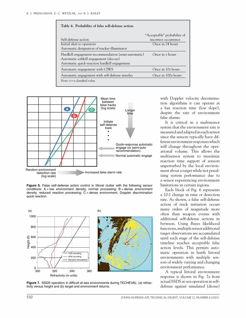
Figure 7. SSDS operation in difficult at-sea environments during TECHEVAL: (a) refrac-tivity versus height and (b) target and environment returns.
with Doppler velocity discrimina-tion algorithms it can operate at a fast reaction time (low slope), despite the rate of environment false alarms.
It is critical in a multisensor system that the environment rate is measured and adapted in each sensor since the sensors typically have dif-ferent environment responses which will change throughout the oper-ational volume. This allows the multisensor system to maximize reaction time support of sensors unperturbed by the local environ-ment about a target while not penal-izing system performance due to a sensor experiencing environment limitations in certain regions.
Each block of Fig. 6 represents a 10:1 change in time or detection rate. As shown, a false self-defense action of track initiation occurs many orders of magnitude more often than weapon events with additional self-defense actions in between. Using Bayes likelihood functions, multiple sensor additional target observations are accumulated until each stage of the self-defense timeline reaches acceptable false action levels. This permits auto-matic operation in harsh littoral environments with multiple sen-sors of widely varying and changing environment performance.
A typical littoral environment response is shown in Fig. 7a from actual SSDS at-sea operation in self-defense against simulated (drone)
Table 4. Probability of false self-defense action.
“Acceptable” probability ofSelf-defense action incorrect occurrenceInitial alert to operators Once in 24 hoursAutomatic designation of tracker illuminator
Hardkill engagement recommendation (semi-automatic) Once in x hoursAutomatic softkill engagement (decoys)Automatic quick-reaction hardkill engagement
Automatic engagement with CIWS Once in 10x hours
Automatic engagement with self-defense missiles Once in 100x hoursNote: x = a classified value.
Mean timebetween
false tracks(log scale)
Initiateself-defense
track
Longertime
Quick-response automaticengage (or semi-autorecommendation)
Normal automatic engage
Increased false alarm rateRandom environment
detection rate(log scale)

JOHNS HOPKINS APL TECHNICAL DIGEST, VOLUME 22, NUMBER 4 (2001) 531
INTEGRATED SHIP DEFENSE
threats. The refractivity measurements made during the test clearly show the presence of a strong sur-face-based duct, which traps the radar radiation in a low-altitude band along the surface of the ocean and allows returns from extremely long ranges to appear ambiguously within the operating region. This effect is a common littoral environment condition in mid- latitudes and stresses the operation of most radar sys-tems. In Fig. 7b, the returns to the northeast and south-west over the ocean originated several hundred miles from the ship and were the source of dense environ-ment false alarms. The detection histories shown in red are primarily from the two drone targets using Doppler discrimination algorithms. The self-defense control pro-cess allowed automatic detection to engagement opera-tion through the difficult scenario.
With the false self-defense action objectives in Table 4 established, the key to successful implementation is translating the false occurrence probability thresholds into criteria that can be used in system decision soft-ware. When a track is evaluated against criteria for ini-tiating some self-defense action, the probability that the action is false is less than or equal to the probability that the track is false. Along with the false track control discussed in preceding paragraphs, the SSDS approach requires good real-time estimation of the probability that a given track is false. The SSDS accomplishes this by inclusion of a dedicated self-defense track quality cal-culation and promotion process in its sensor coordina-tion and control (SCC) function.
The SCC self-defense track quality (SDTQ) estima-tion process establishes an initial SDTQ for a given track based on a priori characterization of the responsible sen-sor’s false track rates and specifics of the sensor measure-ment supporting the track start. For instance, the SSDS
Table 5. Example SSDS engagement doctrine statement.
Criteria RAM CIWS DDIa softkillCategory Air Air AirID threshold Unknown Unknown UnknownPlatform (—)b (—) (—)Track source Radar Radar AnyNo. invalid mode 4 1 0 0
Max. CPAc (kyd) (—) (—) (—)Min. speed (kt) 500 500 (—)Altitude (ft 100) (—) (—) (—)
ES power adequate (—)Tactical response Normal Sensitive Normal
Automation level Auto Auto Semi-autoNo. missiles authorized 2aDDI = Decoy/deceptive ECM integration.b(—) denotes criteria that can be entered by an operator; a blank denotes criteria that cannot be entered by the operator because they do not apply to the weapon.cCPA = closest point of approach.
local tracker for the AN/SPS-49A radar is designed to disclose high-quality single-detection tracks with a mean time between false tracks (MTBFT) of one in 24 hours. If we let the SSDS SDTQ = log(MTBFT in hours), then the SSDS would assign an SDTQ of 1.38 for initial tracks of this type. This track quality value would then be incre-mented (or decremented) according to additional sensor detections (or misses) on subsequent detection opportu-nities. Each increment or decrement is a function of the specific sensor, the locally estimated MTBFT, and the track’s hit/miss detection history.
The SSDS compares a track’s computed SDTQ to specified thresholds (such as those in Table 4) to decide if it can be ordered for engagement or some other self-defense action. The exact threshold values are selected and approved ahead of time and specified in “doctrine statements” that are assigned by operators to specific geographic sectors around the ship. Table 5 shows an example SSDS engagement doctrine statement. Note the additional criteria. When a track attains an SDTQ equal to or greater than the threshold associated with the “tactical response” entry (and meets all other crite-ria specified in a doctrine statement), it is then automat-ically ordered by the SSDS for the specified self-defense action (e.g., automatic RAM engagement).
The qualitative entries selectable for the “tactical response” criterion (e.g., “Normal”) are mapped in soft-ware to a fixed, predefined SDTQ threshold for each weapon. In this way, the ship’s officers can select just how sensitive a response they want. For example, in a stressing situation they might desire automated engage-ment at a lower (than “Normal”) track quality and be willing to accept a slightly higher chance of false self-defense action, so they might invoke a doctrine state-ment with a “Sensitive” tactical response criterion.

532 JOHNS HOPKINS APL TECHNICAL DIGEST, VOLUME 22, NUMBER 4 (2001)
R. J. PRENGAMAN, E. C. WETZLAR, and R. J. BAILEY
Obviously, the quicker a track is promoted to the requisite SDTQ, the quicker it can satisfy active engage-ment doctrine and be ordered by the SSDS for engage-ment and weapon scheduling. But reliance on traditional rotating radars like the SPS-49A and SPS-48E will not always yield high-quality (low MTBFT) firm tracks at ranges sufficient to support desired layered engagement responses. High-speed inbound targets cover significant distance during the time it can take to promote tracks based on detections at multisecond azimuth scan inter-vals, resulting in decreased range available for engage-ment and intercepts.
A significant way that the SSDS addresses this prob-lem is by automated handoff to integrated fire control radars, Phalanx CIWS track radars for SSDS Mk 1, and NATO Seasparrow tracker/illuminators in the case of SSDS Mk 2. Based on track range requirements for weapon engagements at specified ranges from ownship, the SSDS SCC function monitors tactically significant tracks and identifies those with insufficient SDTQ to sat-isfy engagement doctrine. It then orders those targets for acquisition by a fire control sensor, schedules the sensor designation, and monitors the acquisition and the target’s track quality. Typically, the low MTBFT, high precision, and high update rate of these sensors provide a measure-ment stream that causes the target’s SDTQ to increase extremely quickly. Once high track quality that satisfies engagement doctrine requirements has been achieved, the SSDS may release the fire control sensor for other uses or keep it on the target through engagement, in which case the high data rate sensor measurements are used for custom weapon support. This track handoff pro-cess allows quick track promotion and satisfaction of engagement doctrine to preserve engagement space, even against targets disclosed at relatively short ranges.
Custom Weapon/Threat ResponseThe previous sections described two primary con-
cepts for integrated ship defense. Composite fire con-trol with layered weapons and sensors provides the achievable solution to top-level PRA requirements while statistical control of self-defense enables the system to respond quickly and automatically in challenging
operational environments. The third primary concept of integrated ship defense, “custom weapon/threat response,” is made possible only where composite fire control and statistical control of self-defense are also implemented. This concept customizes the sensor and weapon response to each individual threat in order to minimize the threat’s ability to use penetration aids to broach the ship’s defenses.
The scope of custom weapon/threat response can be appreciated by considering that roughly 100 ASCM variants exist in current, developmental, or projected configurations. Each of these threat types uses its own methods for penetrating ship defensive systems. These can be profiles which include “doglegs,” stepdowns, weaves, dives, turnouts, and multidimensional maneu-vers; countermeasures either onboard the missile or from external support systems; signature reductions to reduce shipboard sensor performance; and multispec-tral seekers to reduce the effectiveness of ship’s decoys or ECMs.
The process of custom weapon/threat response in the SSDS begins with the kinematic identification of the threat profile, aided by any threat seeker information extracted by ESM sensors. This process is enhanced by processing, in parallel, multiple Kalman filters with dif-fering assumptions relative to threat trajectory. In all cases, weapons filters are implemented with multisen-sor data to prevent susceptibility to ECMs or propaga-tion effects. This differs markedly from earlier stand-alone fire control radar designs which, when defeated by the threat’s onboard or support countermeasures, could allow a catastrophic breakdown in ship defense.
An example of SSDS custom weapon support is shown in Fig. 8 from at-sea operation aboard the Self-Defense Test Ship (SDTS). Here, custom track filters designed and implemented by APL engineers allow engagement of high-diver supersonic Vandal missiles using low-data-rate limited-accuracy elevation from the SPS-49A radar. Without the custom filters, the ship could not defend against this important threat case. Custom weapon/threat response was a critical issue in the growth of the SSDS from Mk 1 to Mk 2 con-figurations. In Mk 2, it was necessary to allocate the
Figure 8. SSDS custom weapon filtering during high-elevation target testing. Left, target track and height display; center, RAM firing while CIWS tracks prepare to fire, if needed; right, successful engagement by RAM.
PrecisionCIWS track
Launch onSPS-49A
track

JOHNS HOPKINS APL TECHNICAL DIGEST, VOLUME 22, NUMBER 4 (2001) 533
INTEGRATED SHIP DEFENSE
composite sensor processing between the CEC and SSDS to accommodate the common tactical requirements of the CEC and the custom weapon/threat response requirements of the SSDS. A description of this alloca-tion and the resulting combat system configuration is the subject of the article by Thomas et al., this issue.
SHIP SELF-DEFENSE TESTING The operational testing of ship self-defense systems
is inherently difficult and dangerous. It is essential to verify that the system will perform under stressing threat and environmental conditions. Conversely, there can be significant risk to the SDTS if flaws exist anywhere in the engagement timelines or if part of the system development is immature. The test sequence needed to validate self-defense performance is well represented by the SSDS Mk 1 testing illustrated in Fig. 9.
SSDS Mk 1 at-sea testing began with a concept dem-onstration in June 1993. This very successful test series verified the fundamental composite sensor and weapon layering concepts and provided a basis for initiating engineering development. At this time full safety certi-fication of system software had not been achieved, so strict safety procedures were required to support live firing events.
SSDS Mk 1 development to a production configu-ration required roughly 2 years and was followed by over a year of land-based testing (at Wallops Island) as illustrated in Fig. 9. This was followed by a very success-ful at-sea OPEVAL and approval for full production. By the time of the OPEVAL, the SSDS was capable of full automatic operation and was safety certified. However, since the OPEVAL platform was a fully manned Fleet ship, threat surrogate targets were limited to subsonic speeds.
Figure 9. SSDS development and operational testing.
The final stressing threat testing was carried out as a follow-on test and evaluation phase aboard the SDTS in conjunction with the newly developed Block 1 vari-ant of the RAM systems. The exceptional performance of the SSDS with RAM during these tests and the use of the SDTS for stressing self-defense tests are the subjects of articles by Elko et al. and York and Bateman, respec-tively, this issue. Of major significance was the ability of the SSDS to operate in unmanned, fully automatic modes against presentations of supersonic threat surro-gates in challenging operational environments, includ-ing surface-based duct conditions similar to those shown in Fig. 7b.
MEASURES OF EFFECTIVENESSAlthough the live firing tests described above are a
key part of self-defense performance evaluation, they are rare events in the roughly 4 years that the SSDS has spent in test phases from concept through development and follow-on test and evaluation. In addition, the cost of ordnance (missile, gun, decoy) and expendable test target assets prohibits the actual measurement of PRA to statistically exact levels. Thus it is extremely important that measures of effectiveness (MOEs) are established which allow measurement of PRA components without live ordnance. The MOEs used for this purpose in the SSDS program, shown in Fig. 10, are applicable to all stages of testing and allow either developers or inde-pendent test teams to develop a statistically meaningful view of performance as well as an excellent measure of system maturity.
An important example is the MOE related to sta-tistical control of self-defense. Each day of operations at a land-based test site, for example, the maturity of automatic operation can be accumulated via measures

534 JOHNS HOPKINS APL TECHNICAL DIGEST, VOLUME 22, NUMBER 4 (2001)
R. J. PRENGAMAN, E. C. WETZLAR, and R. J. BAILEY
of reaction time and false self-defense actions without, of course, an actual weapon launch. Until these levels reach the very high probabilities described earlier, the self-defense system will not fully meet its critical mission.
PERSPECTIVE: THE PAST AND FUTURE OF SSDS
The development of SSDS Mk 1 and its evolution to multiple SSDS Mk 2 configurations involve an excep-tional partnership among APL, industry, and govern-ment program organizations. In presenting the Hammer Award to the SSDS program in 1998, the Under Secretary of Defense for Acquisition and Technology observed that the actual development cost of the system was less than proposed in 1995, largely because nearly half of the software used was nondevelopmental or was written for other programs and adopted for use at sig-nificantly reduced cost. This “50%” was provided by the APL team and, in addition to the large cost sav-ings, was the enabling technology in distributed infra- structure, composite sensor processing, and false track control that formed the concept and performance base-line of the system.
The SSDS program involved the rare opportunity to develop a new combat system capability with very few restrictions of legacy equipment, interfaces, or pro-cessing. Under these unusual conditions, the combined APL, industry, and government team was an excellent match to the opportunity.
PRA and combatcornerstones
Composite fire control
Statistical control ofself-defense
Custom weapon/threatresponse
Probability of establishing validfirm track
Probability of maintaining firmtrack quality
Probability of achievingautomatic mode reacting time
Probability of correct engagementdecision for hostile targets and no
engagements of false/friendly
Probability of correctengagement sequence by
correct weapon at the right time
Top-level requirements Concepts MOEs
Figure 10. Ship self-defense measures of effectiveness.
The evolution of the system to the Mk 2 Mod 0 con-figuration for CVN 68 was significantly enhanced by (1) a technology refresh of key software (infrastructure and display kernel) by the APL team at program initiation and (2) support to industry during develop-ment in utilization of off-board measurements from the CEC in custom weapon/threat response algorithms. The common heritage of the CEC and SSDS at APL is a major benefit in efficient SSDS evolution.
The important Navy decision to extend the SSDS architecture to include former Advanced Combat Direc-tion System functions completes the application of dis-tributed open system technology through carrier and major amphibious classes. We have shown that this architecture was required in the SSDS to achieve top-level PRA requirements via a combination of weapon and sensor “layering.” Similar benefits will be achieved in other warfare areas as well.
The inclusion of solid-state phased array radars and precision ESM sensors in follow-on combat systems nearly completes the early NATO AAW vision of optional ship defense sensor suites. The new radar tech-nology will enable littoral AAW operations free of deg-radation from clutter and allow significantly greater customization of weapons response to stressing threat characteristics. Most importantly, the advanced sen-sors, along with CEC networking of Fleet assets, can be expected to bridge the area defense and self-defense mission operation, allowing a continuous force-level achievement of ship defense at performance levels not possible with stand-alone ship defense.

JOHNS HOPKINS APL TECHNICAL DIGEST, VOLUME 22, NUMBER 4 (2001) 535
INTEGRATED SHIP DEFENSE
THE AUTHORS
RICHARD J. PRENGAMAN received his B.S. degree in electrical engineering from Carnegie Mellon University in 1965 and his M.S. degree in numerical science from The Johns Hopkins University in 1972. He joined APL in 1969 and has been a member of the Principal Professional Staff since 1981. He is currently the Chief Combat Systems Engineer of the Air Defense Systems Department. Mr. Prengaman has an extensive background in Navy radar and missile integration systems and has been the technical director of several large programs in which APL served a design agent role for the Navy in “first-of-a-kind” systems development. These included the AN/SYS-1 and AN/SYS-2 automatic detection and tracking systems in the late 1970s and early 1980s as well as the Ship Self-Defense System (Mk 1 and Mk 2) from 1992 to 2000. From 1986 through 1990 he led a six-country international team of sensor experts in the definition of advanced combat systems for NATO Shipboard Air Defense. His e-mail address is [email protected].
EDWARD C. WETZLAR is a member of APL’s Principal Professional Staff and Assistant Program Manager for integrated ship defense systems in ADSD’s Air Defense Systems Program Office Group. He received a B.S. and M.S. in electrical engineering from the University of Florida and joined APL in 1968 where he per-formed analysis, test, and evaluation of submarine navigation systems. After join-ing the Fleet Systems Department in 1974, he performed analysis, test, and evalua-tion of radar integrated automatic detection and tracking systems, combat systems, and the FAA’s en route tracking system. He also worked on the development of the FAA’s active air safety program. Mr. Wetzlar was a project engineer in the concept exploration phase of NATO’s Anti-Air Warfare program and the first Navy distrib-uted processing architecture Ship Self-Defense Quick-Reaction Combat Capability Demonstration. He served as Project Manager during the development of the SSDS Mk 1 and Mk 2 Combat Systems. His e-mail address is [email protected].
ROBERT J. BAILEY is a member of APL’s Principal Professional Staff, Supervisor of the Combat Systems Analysis Section in ADSD’s Combatant Integration Group, and Technical Direction Agent lead for the SSDS Program. He received a B.S. in mathematics and physics from Principia College in 1980 and an M.S. in com-puter science from JHU in 1985. Since joining APL in 1980, his work has largely comprised computer simulation and evaluation of shipboard radar, integrated sensor suite, and combat system performance in support of numerous Navy Surface Fleet programs. With an emphasis on sensor and combat system integration, Mr. Bailey has led requirements definition and conducted extensive performance analyses sup-porting the development of the SSDS Mk 1 and Mk 2 since inception in 1991. His e-mail address is [email protected].