Integrated Motion on SERCOS and EtherNet/IP Systems ...
149
Integrated Motion on SERCOS and EtherNet/IP Systems - Analysis and Comparison The purpose of this document is to compare and contrast Integrated Motion systems using SERCOS and EtherNet/IP with a ControlLogix ® Programmable Automation Controller (PAC). Topics covered include the systems’ hardware, axis configurations, Get System Variable (GSV) and System Set Variable (SSV), and axis exceptions. Contents 0HHardware ...................................................................................................................................... 26H2 1HFeatures ....................................................................................................................................... 27H3 2HTopology ....................................................................................................................................... 28H4 3HCommunication Module & Drive Configuration ............................................................................ 29H5 4HAxis Configuration ...................................................................................................................... 30H10 5HAxis Commissioning ................................................................................................................... 31H21 6HAdditional Axis Property Equivalents ......................................................................................... 32H34 7HDiagnostics ................................................................................................................................. 33H41 8HAxis Structure ......................................................................................................................... 34H41 9HFaults & Alarms Log ............................................................................................................... 35H42 10HKinetix 6500 Embedded Webpage ......................................................................................... 36H43 11HSupplemental Information .......................................................................................................... 37H48 12HAppendix A – Ethernet Communication Module Drive Limits ................................................. 38H48 13HAppendix B – Kinetix 6500 IP Address Assignment ............................................................... 39H49 14HAppendix C – Additional Topology Examples......................................................................... 40H50 15HAppendix D – Drive Parameters Cyclic Read/Write List ......................................................... 41H52 16HAppendix E – Available GSV & SSV Data .............................................................................. 42H53 17HAppendix F – Axis Attributes................................................................................................... 43H61 18HAppendix G – Axis Exceptions.............................................................................................. 44H108 19HAdditional Resources ............................................................................................................... 45H148
Transcript of Integrated Motion on SERCOS and EtherNet/IP Systems ...

Integrated Motion on SERCOS and EtherNet/IP Systems - Analysis and Comparison
The purpose of this document is to compare and contrast Integrated Motion systems using SERCOS and EtherNet/IP with a ControlLogix® Programmable Automation Controller (PAC). Topics covered include the systems’ hardware, axis configurations, Get System Variable (GSV) and System Set Variable (SSV), and axis exceptions.
Contents
0HHardware ...................................................................................................................................... 26H2
1HFeatures ....................................................................................................................................... 27H3
2HTopology....................................................................................................................................... 28H4
3HCommunication Module & Drive Configuration ............................................................................ 29H5
4HAxis Configuration ...................................................................................................................... 30H10
5HAxis Commissioning ................................................................................................................... 31H21
6HAdditional Axis Property Equivalents ......................................................................................... 32H34
7HDiagnostics ................................................................................................................................. 33H41
8HAxis Structure ......................................................................................................................... 34H41
9HFaults & Alarms Log ............................................................................................................... 35H42
10HKinetix 6500 Embedded Webpage ......................................................................................... 36H43
11HSupplemental Information .......................................................................................................... 37H48
12HAppendix A – Ethernet Communication Module Drive Limits................................................. 38H48
13HAppendix B – Kinetix 6500 IP Address Assignment............................................................... 39H49
14HAppendix C – Additional Topology Examples......................................................................... 40H50
15HAppendix D – Drive Parameters Cyclic Read/Write List......................................................... 41H52
16HAppendix E – Available GSV & SSV Data.............................................................................. 42H53
17HAppendix F – Axis Attributes................................................................................................... 43H61
18HAppendix G – Axis Exceptions.............................................................................................. 44H108
19HAdditional Resources ............................................................................................................... 45H148

2 | Integrated Motion on SERCOS and EtherNet/IP - Analysis and Comparison
0BHardware
The following table lists the hardware information for Integrated Motion on SERCOS and EtherNet/IP systems.
Integrated Motion on SERCOS System Integrated Motion on EtherNet/IP System
• SERCOS II technology
• Controller 1756-L6x, 1756-L7x, GuardLogix, 1768-L43, 1768-L45
• SERCOS card 1756-M03SE, 1756-M08SE, 1756-M16SE and 1768-M04SE
• Servo Drives Ultra™
3000 SE, Kinetix® 2000,
Kinetix® 6000, Kinetix
® 6200 and
Kinetix® 7000
• EtherNet/IP technology
• Controller 1756-L6x , 1756-L7x, GuardLogix
• Ethernet communication 1756-EN2T, 1756-EN2F, 1756-EN2TR and 1756-EN3TR
• Kinetix® 6500 Servo drive, PowerFlex® 755 AC drive
• 1783-ETAP, 1783-ETAP1F and 1783-ETAP2F EtherNet/IP taps with embedded switch technology (optional)
• Stratix 2000™, Stratix 6000™, Stratix 8000™, and/or commercially available switches (optional)

3 | Integrated Motion on SERCOS and EtherNet/IP - Analysis and Comparison
1BFeatures
The following table lists features for Integrated Motion on SERCOS and EtherNet/IP systems.
Integrated Motion on SERCOS System Integrated Motion on EtherNet/IP System
• SERCOS (Serial Real-time Communications System) is a controller/drive interface using noise-immune, fiber optic cables.
• A single fiber optic ring serves as the sole interface between control and drive. It replaces costly command and feedback wiring, reducing both installation time and wiring costs.
• Kinetix provides advanced diagnostics and process reporting via the SERCOS interface.
• Wide variety of motion module options for ControlLogix, CompactLogix and GuardLogix.
• Up to 16 axes of motion can be controlled from one motion module.
• System is fully expandable, with up to 100 axes supported per controller.
• Multiple controllers can be used if additional axes are needed.
• Single network architecture integrates high performance drives, I/O, smart actuators, HMI, programming terminal, and any other EtherNet/IP device providing lower system cost, improved performance, flexibility, and ease-of-use benefits.
• Extends the benefits and simplicity of Integrated Motion to Kinetix 6500 and PowerFlex 755 drives on EtherNet/IP.
• Kinetix and PowerFlex drives can be used on the same network – for common configuration, programming, commissioning, diagnostics, and drive maintenance.
• EtherNet/IP is open and broadly adopted with over 3 million installed nodes, and over 1000 different products as of 2011.
• EtherNet/IP, CIP Motion, and CIP Sync technologies are global standards from ODVA, helping to ensure device standardization and compatibility.
• Support for any Ethernet topology for maximum flexibility. Kinetix 6500 has embedded switch DLR technology.
• EtherNet/IP is an agile, multidiscipline network that can be used to control, configure, monitor and do peer interlocking for motion, safety, process and discrete applications; it provides true enterprise-wide integration.
• This is a flexible network and can be used to connect business, commercial and industrial devices to help simplify networking, save time and reduce costs.

4 | Integrated Motion on SERCOS and EtherNet/IP - Analysis and Comparison
2BTopology
The following table lists information on the topologies for Integrated Motion on SERCOS and EtherNet/IP systems.
Integrated Motion on SERCOS System Integrated Motion on EtherNet/IP System
• SERCOS II technology, 8 MB transmission rate
• Maximum of 16 drives per SERCOS module or ring, supports multiple SERCOS modules per controller
• Dedicated motion network, supports only SERCOS interface drives
• Limited to ring topology only
• EtherNet/IP technology, 100 MB “Fast Ethernet”
• Standard unmodified Ethernet
• Maximum of 128 drives per Ethernet module
• Any combination of EtherNet/IP devices on a common network: AC and servo drives, distributed I/O, EOI, and any other EtherNet/IP device
• Support for any Ethernet topology including: star, linear, ring (Device Level Ring or DLR) or hybrid
NOTE: A 1756-L7x controller motion group is limited to 100 axes. Multiple controllers can control drives on a common Ethernet module.
Ring Topology Basic Linear/Ring Topology
NOTE: For additional topology examples please refer to 20HAppendix C – Additional Topology Examples.

5 | Integrated Motion on SERCOS and EtherNet/IP - Analysis and Comparison
3BCommunication Module & Drive Configuration
Integrated Motion on SERCOS System Integrated Motion on EtherNet/IP System
Selecting SERCOS Communication Module Selecting Ethernet Communication Module
Select the appropriate SERCOS communication module:
• 1756-M03SE � 3 SERCOS drives
• 1756-M08SE � 8 SERCOS drives
• 1756-M16SE � 16 SERCOS drives
Select the appropriate Ethernet communication module:
• 1756-EN2x � Up to 128 EtherNet/IP drives with a maximum of 8 Position Configured drives
• 1756-EN3x � Up to 128 EtherNet/IP drives
NOTE: For additional information on the Ethernet communication module axis limits, please refer to 21HAppendix E – Ethernet Communication Module Drive Limits.

6 | Integrated Motion on SERCOS and EtherNet/IP - Analysis and Comparison
Integrated Motion on SERCOS System Integrated Motion on EtherNet/IP System
Drive Selection Drive Selection: Control & Power Structure
When selecting a SERCOS drive, the user is selecting both the control and power structure.
For an EtherNet/IP drive, the user selects control and power structure separately.
First, the control module is selected.
Then, on the module definition for the control module, the power structure is selected.
NOTE: The power structure can now be changed without having to re-add the drive.

7 | Integrated Motion on SERCOS and EtherNet/IP - Analysis and Comparison
Integrated Motion on SERCOS System Integrated Motion on EtherNet/IP System
Set Node Address Set IP Address
Each SERCOS drive must have a unique identifier which is its node address.
Each EtherNet/IP drive must have a unique identifier which is its IP address.
NOTE: The IP address for the Kinetix 6500 drive can be assigned as Isolated, Static, Dynamic (BOOTP/DHCP) or DHCP Persistence.
For additional information on how to set the IP address, please refer to 22HAppendix B – Kinetix 6500 IP Address Assignment.

8 | Integrated Motion on SERCOS and EtherNet/IP - Analysis and Comparison
Integrated Motion on SERCOS System Integrated Motion on EtherNet/IP System
Configuring SERCOS Communication Module Configuring Ethernet Communication Module
Select the appropriate data rate, cycle time, etc. that matches the SERCOS network. These settings are typically dependent on the number of drives in the network.
Set the module definition Time Sync Connection to Time Sync and Motion. This enables CIP Sync time coordination required for motion control.
Digital Inputs Configurable Digital Inputs
SERCOS drives contain up to 6 digital inputs. Typically the function of these inputs cannot be configured.
EtherNet/IP drives have configurable digital inputs. For example, the Kinetix 6500 has 4 configurable inputs.

9 | Integrated Motion on SERCOS and EtherNet/IP - Analysis and Comparison
Integrated Motion on SERCOS System Integrated Motion on EtherNet/IP System
Drive Enable Input Checking Example Drive Enable Input Checking Example
For a SERCOS drive, the Drive Enable Input Checking checkbox is located on the Drive/Motor tab of the Axis Properities.
For an EtherNet/IP drive, to disable input checking for example, make sure none of the inputs are assigned to enable.
Hard Travel Limits Example Overtravel Limits Example
For a SERCOS drive, the Hard Travel Limits checkbox is located on the Limits tab of the Axis Properties.
For an EtherNet/IP drive, to enable the hard travel limits, assign the inputs to Positive / Negative Overtravel.
NOTE: The Kinetix 6200 drive is limited to 4 digitals.
The digital input default settings can be configured by using a SERCOS IDN write instruction.
NOTE: The following digital inputs can be assigned for the Kinetix 6500 drives.
10 | Integrated Motion on SERCOS and EtherNet/IP - Analysis and Comparison
4BAxis Configuration
Integrated Motion on SERCOS System Integrated Motion on EtherNet/IP System
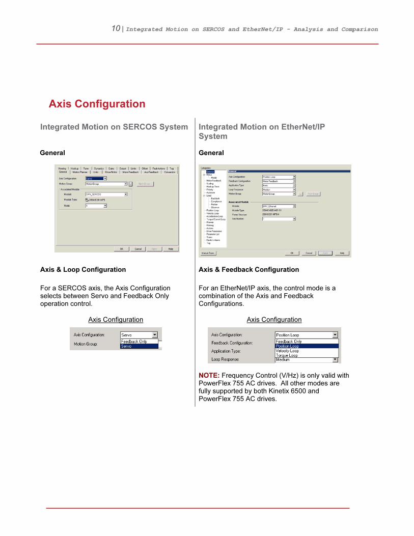
General General
Axis & Loop Configuration Axis & Feedback Configuration
For a SERCOS axis, the Axis Configuration selects between Servo and Feedback Only operation control.
For an EtherNet/IP axis, the control mode is a combination of the Axis and Feedback Configurations.
Axis Configuration
Axis Configuration
NOTE: Frequency Control (V/Hz) is only valid with PowerFlex 755 AC drives. All other modes are fully supported by both Kinetix 6500 and PowerFlex 755 AC drives.

11 | Integrated Motion on SERCOS and EtherNet/IP - Analysis and Comparison
Integrated Motion on SERCOS System Integrated Motion on EtherNet/IP System
To configure the axis for Velocity Servo, Torque Servo, etc., refer to the Loop Configuration located on the Drive/Motor tab.
Loop Configuration
Feedback Configuration
12 | Integrated Motion on SERCOS and EtherNet/IP - Analysis and Comparison
Integrated Motion on SERCOS System Integrated Motion on EtherNet/IP System
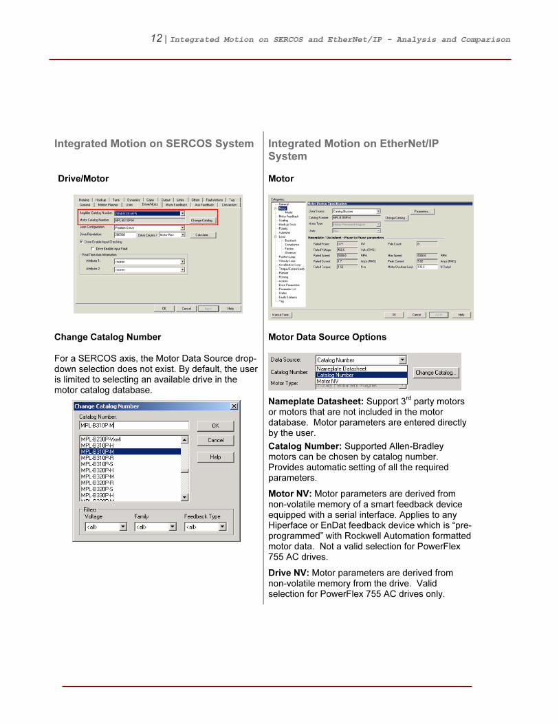
Drive/Motor Motor
Change Catalog Number Motor Data Source Options
For a SERCOS axis, the Motor Data Source drop-down selection does not exist. By default, the user is limited to selecting an available drive in the motor catalog database.
Nameplate Datasheet: Support 3rd
party motors or motors that are not included in the motor database. Motor parameters are entered directly by the user.
Catalog Number: Supported Allen-Bradley motors can be chosen by catalog number. Provides automatic setting of all the required parameters.
Motor NV: Motor parameters are derived from non-volatile memory of a smart feedback device equipped with a serial interface. Applies to any Hiperface or EnDat feedback device which is “pre-programmed” with Rockwell Automation formatted motor data. Not a valid selection for PowerFlex 755 AC drives.
Drive NV: Motor parameters are derived from non-volatile memory from the drive. Valid selection for PowerFlex 755 AC drives only.
13 | Integrated Motion on SERCOS and EtherNet/IP - Analysis and Comparison
Integrated Motion on SERCOS System Integrated Motion on EtherNet/IP System
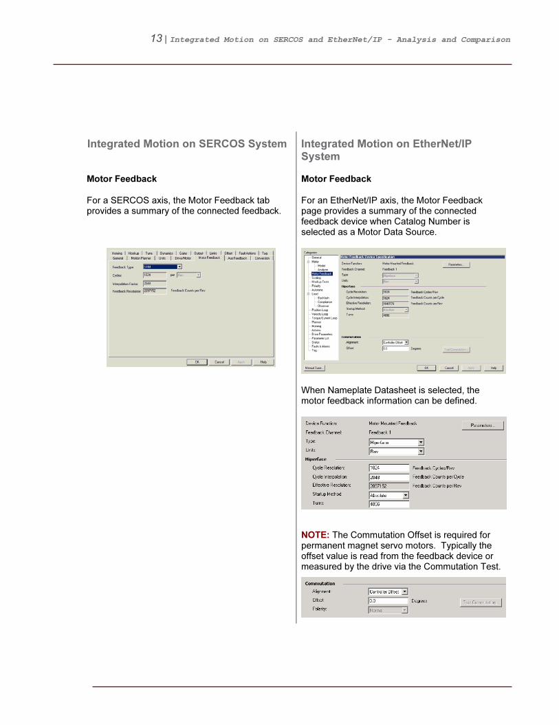
Motor Feedback Motor Feedback
For a SERCOS axis, the Motor Feedback tab provides a summary of the connected feedback.
For an EtherNet/IP axis, the Motor Feedback page provides a summary of the connected feedback device when Catalog Number is selected as a Motor Data Source.
When Nameplate Datasheet is selected, the motor feedback information can be defined.
NOTE: The Commutation Offset is required for permanent magnet servo motors. Typically the offset value is read from the feedback device or measured by the drive via the Commutation Test.

14 | Integrated Motion on SERCOS and EtherNet/IP - Analysis and Comparison
Integrated Motion on SERCOS System Integrated Motion on EtherNet/IP System
Aux Feedback Load Feedback
The Aux Feedback page is not accessible unless one of the conditions is true:
• Axis Configuration is set to Feedback Only
• Loop Configuration is set to “Aux” or “Dual” loop mode
The Load Feedback page is only visible if the Feedback Configuration is set to Load or Dual Feedback.
Master Feedback
If the Axis Configuration is set to Feedback Only, the Motor and Load Feedback pages are replaced by Master Feedback page.

15 | Integrated Motion on SERCOS and EtherNet/IP - Analysis and Comparison
Integrated Motion on SERCOS System Integrated Motion on EtherNet/IP System
Conversion Constant Scaling Calculator
Position Units Units
For a SERCOS axis, the Position Units are located on the Units tab.
The scaling units are user defined and will be reflected through-out the Axis Properties.
Transmission Ratio & Actuator
For a SERCOS axis, the Transmission Ratio and Actuator entry does not exist. These input values must be directly included in the Convesion Constant and Drive Resolution calculations.
The Tranmission Ratio and Actuator entry makes it easier to enter application specific scaling information. For the Actuator, select from Screw, Belt-&-Pulley, Chain-&-Sprocket and Rack-&-Pinion.
16 | Integrated Motion on SERCOS and EtherNet/IP - Analysis and Comparison
Integrated Motion on SERCOS System Integrated Motion on EtherNet/IP System
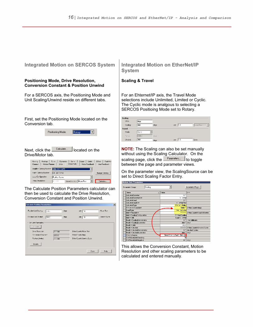
Positioning Mode, Drive Resolution, Conversion Constant & Position Unwind
Scaling & Travel
For a SERCOS axis, the Positioning Mode and Unit Scaling/Unwind reside on different tabs.
For an Ehternet/IP axis, the Travel Mode selections include Unlimited, Limited or Cyclic. The Cyclic mode is analgous to selecting a SERCOS Positioing Mode set to Rotary.
First, set the Positioning Mode located on the Conversion tab.
Next, click the located on the Drive/Motor tab.
The Calculate Position Parameters calculator can then be used to calculate the Drive Resolution, Conversion Constant and Position Unwind.
NOTE: The Scaling can also be set manually without using the Scaling Calculator. On the
scaling page, click the to toggle between the page and parameter views.
On the parameter view, the ScalingSource can be set to Direct Scaling Factor Entry.
This allows the Conversion Constant, Motion Resolution and other scaling parameters to be calculated and entered manually.

17 | Integrated Motion on SERCOS and EtherNet/IP - Analysis and Comparison
Integrated Motion on SERCOS System Integrated Motion on EtherNet/IP System
Homing Homing
Homing Mode Homing Mode
The Active and Passive homing modes for both SERCOS and EtherNet/IP axes have similar functions.
Active: The desired homing sequence is selected by specifying whether a home limit switch or the encoder marker is used for this axis. Active homing sequences always use the trapezoidal velocity profile.
Passive: Homing redefines the absolute position of the axis on the occurrence of a home switch or encoder marker event. Passive homing is most commonly used to calibrate uncontrolled axes, although it can also be used with controlled axes to create a custom homing sequence.
Absolute: The absolute homing process establishes the true absolute position of the axis by applying the configured Home Position to the reported position of the absolute feedback device.
NOTE: The only valid Home Sequence for an absolute Homing Mode is immediate.
NOTE: For an EtherNet/IP axis, if the motor contains an absolute position capable feedback device the homing operation will automatically set the absolute position.

18 | Integrated Motion on SERCOS and EtherNet/IP - Analysis and Comparison
Integrated Motion on SERCOS System Integrated Motion on EtherNet/IP System
Homing Sequence Homing Sequence
NOTE: EtherNet/IP axes currently do not support the home to Torque Level sequence. This functionality can be implemented via software in your RSLogix 5000 project.
Please refer to 23HSample Code Library: Filename/ID 055818 – CIP Axis Home To Torque AOI
This sample code example demonstrates one method to execute a Home to Torque Level sequence in RSLogix 5000 application code.

19 | Integrated Motion on SERCOS and EtherNet/IP - Analysis and Comparison
Integrated Motion on SERCOS System Integrated Motion on EtherNet/IP System
Fault Actions Fault Actions
A SERCOS axis is limited to a total 9 Fault Actions.
For an EtherNet/IP axis, the Fault Actions referred to as Exception Conditions, see 24HAppendix G – Axis Exceptions. The number of configurable conditions has been significantly expanded.
Drive Enable Input Fault Example Action – Enable Input Deactivated Example
For SERCOS axis, the Drive Enable Input Fault checkbox is located on the Drive/Motor tab. Uncheck this box to ignore this this fault.
For an EtherNet/IP axis, all of the Enable Input Deactivated Actions (including Ignore) are available on the Actions page.
Otherwise assign the approiate Fault Action.
Typically the following Actions are available:
NOTE: The available Actions can vary between Exception Conditions.

20 | Integrated Motion on SERCOS and EtherNet/IP - Analysis and Comparison
Integrated Motion on SERCOS System Integrated Motion on EtherNet/IP System
Real Time Axis Information Drives Parameters
For a SERCOS axis, 2 additional real time attributes can be selected in addition to default Auto Tag Update attributes. The attributes updatedat the coarse update rate and are read-only.
An EtherNet/IP axis supports up to 10-read and 10-write parameters. These parameters are transferred at the cyclic/coarse rate and are available in the axis structure. For a detailed list, please refer to 25HAppendix D – Drive Parameter Cyclic Read/Write List.
NOTE: Each parameter selected as a cyclic read/write attribute will add overhead to the controller / drive data exchange and thus impact throughput. The user must analyze the trade-off of real time data on the timing of the axis.
NOTE: In order to obtain Real Time Axis Information for both SERCOS and EtherNet/IP axes, Auto Tag Update needs to enabled.
In addition to selected attributes, the following 8-read only default attributes are automatically updated at the coarse update rate:
• ActualPosition
• CommandPosition
• ActualVelocity
• CommandVelocity
• ActualAcceleration
• CommandAcceleration
• AverageVelocity
• MasterOffset

21 | Integrated Motion on SERCOS and EtherNet/IP - Analysis and Comparison
5BAxis Commissioning
Integrated Motion on SERCOS System Integrated Motion on EtherNet/IP System
Hookup Tests Hookup Tests
The Hookup Tests interfaces between the SERCOS and EtherNet/IP axes are similar.
The Hookup Tests are used to verify the proper hookup of the feedback device and to determine motor and feedback polarity.
NOTE: The Hookup Tests for both SERCOS and EtherNet/IP Axes can be executed while the controller is in Program Mode.

22 | Integrated Motion on SERCOS and EtherNet/IP - Analysis and Comparison
Integrated Motion on SERCOS System Integrated Motion on EtherNet/IP System
Commutation Test
NOTE: For a SERCOS axis, the Commutation Test does not exist as this feature is not supported.
For an EtherNet/IP axis, the Hookup Tests can also measure the Commutation Offset for permanent magnet servo motors.
NOTE: Measuring the Commutation Offset is typically required when operating 3
rd party servo
motors and/or when using PowerFlex 755 AC drives.

23 | Integrated Motion on SERCOS and EtherNet/IP - Analysis and Comparison
Integrated Motion on SERCOS System Integrated Motion on EtherNet/IP System
Drive Polarity Polarity
For a SERCOS axis, the Drive Polarity is updated based on the results of the Hookup Tests. The Drive Polarity setting is located on the Hookup tab.
For an EtherNet/IP axis, the Motion Polarity, Motor Polarity and Feedback Polarity(s) are updated based on the results of the Hookup Tests.
NOTE: The Drive Polarity for a SERCOS axis cannot be manually changed while online with controller.
IMPORTANT: It is recommended to use the Hookup Tests to correctly adjust polarity settings. Incorrectly adjusting the polarity settings can lead to an axis runaway condition.

24 | Integrated Motion on SERCOS and EtherNet/IP - Analysis and Comparison
Integrated Motion on SERCOS System Integrated Motion on EtherNet/IP System
Tune Autotune
Tune Settings Application Type
For a SERCOS axis, the Application Type drop-down selection does not exist. Instead the user must select the individual tuning parameters.
The application type selection provides automatic setting of the servo loop configuration and loop gains.
Custom Basic Tracking Point -to-
Point
Constant Speed
Position Loop Bandwidth X X X X X
Position Integrator Bandwidth
X
Velocity Loop Bandwidth X X X X X
Velocity Integrator Bandwidth
X X
Integrator Hold X
Velocity Feedforward
(1) X X
Acceleration Feedforward
(1) X
X – Selected by default
(1) – Velocity and Acceleration Feedforward will be set to 100%

25 | Integrated Motion on SERCOS and EtherNet/IP - Analysis and Comparison
Integrated Motion on SERCOS System Integrated Motion on EtherNet/IP System
Application Type continued
Custom: Advanced setup, user selects specific tuning parameters based on the application.
Basic: Default setup. Recommended as starting point for “out of the box” configurations.
Tracking: Intended for applications that require minimal following error. Ex: Un/Winding, Flying Shear and Web Control Applications
Point-to-Point: Intended for applications that require precise position moves with minimal overshoot. Ex: Pick-N-Place, Packaging and Cut-to-Length Applications
Constant Speed: Intended for applications that require minimal velocity error at steady state speed. Ex: Conveyors, Line Shaft and Crank Applications

26 | Integrated Motion on SERCOS and EtherNet/IP - Analysis and Comparison
Integrated Motion on SERCOS System Integrated Motion on EtherNet/IP System
Damping Factor Loop Response
For a SERCOS axis, the Loop Response drop-down selection does not exist. Instead the user must enter the desired damping factor.
Low: Damping Factor = 1.5
Medium: Damping Factor = 1.0 Default setting, recommended as starting point for “out of the box” configurations.
High: Damping Factor = 0.8
NOTE: The Damping Factor is used to calculate the maximum Position and Velocity Servo Bandwidth values. In general, the Damping Factor controls the dynamic response of the drive.
When the tuning gains are calculated using a small Damping Factor, for example 0.8, a step response test tends to demonstrate an under-damped behavior with velocity overshoot.
However, when the Damping Factor is increased to 1.0, the step response tends to exhibit little to no overshoot and typically works well for most applications.
Load Coupling
For a SERCOS axis, the Load Coupling drop-down selection does not exist as this feature is not supported.
The Load Coupling automatically corrects the loop gains based on how tightly the system is physically coupled.
27 | Integrated Motion on SERCOS and EtherNet/IP - Analysis and Comparison
Integrated Motion on SERCOS System Integrated Motion on EtherNet/IP System
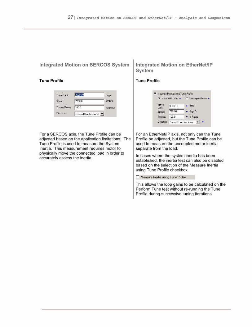
Tune Profile Tune Profile
For a SERCOS axis, the Tune Profile can be adjusted based on the application limitations. The Tune Profile is used to measure the System Inertia. This measurement requires motor to physically move the connected load in order to accurately assess the inertia.
For an EtherNet/IP axis, not only can the Tune Profile be adjusted, but the Tune Profile can be used to measure the uncoupled motor inertia separate from the load.
In cases where the system inertia has been established, the inertia test can also be disabled based on the selection of the Measure Inertia using Tune Profile checkbox.
This allows the loop gains to be calculated on the Perform Tune test without re-running the Tune Profile during successive tuning iterations.

28 | Integrated Motion on SERCOS and EtherNet/IP - Analysis and Comparison
Integrated Motion on SERCOS System Integrated Motion on EtherNet/IP System
Tune Results Tune Results
Upon completion of the Autotune, a SERCOS axis will display the Loop Bandwidth and measured Load Inertia Ratio. The user can choose to select these results by clicking OK.
For an EtherNet/IP axis, a more encompassing list of both Loop and Load Parameters are displayed to the user.
The ‘*’ next to the parameters indicates which values will be updated. The user can choose to select these results by pressing the
.

29 | Integrated Motion on SERCOS and EtherNet/IP - Analysis and Comparison
Integrated Motion on SERCOS System Integrated Motion on EtherNet/IP System
Manual Tuning – Manual Adjustment & Motion Direct Commands
Manual Tuning
For a SERCOS axis, the Manual Adjust interface is limited to adjustment of the tuning related parameters only.
The Manual Tuning interface consolidates many of the commonly used features utilized during the tuning process.

30 | Integrated Motion on SERCOS and EtherNet/IP - Analysis and Comparison
Integrated Motion on SERCOS System Integrated Motion on EtherNet/IP System
Motion Direct Commands Motion Generator
For a SERCOS axis, the user typically will need to launch the Motion Direct Commands in order to manually control the drive during the tuning process.
As a part of the Manual Tuning interface, the Motion Generator feature includes direct access to several of the most commonly used Motion Direct Commands. This reduces the need to launch the Motion Direct Commands interface to complete the tuning process.

31 | Integrated Motion on SERCOS and EtherNet/IP - Analysis and Comparison
Integrated Motion on SERCOS System Integrated Motion on EtherNet/IP System
Gains Manual Tune – Loop Gains
For a SERCOS axis, the gains can only be adjusted individually via the Manual Adjust interface.
The Manual Tuning interface now offers 2 options to manually adjust the loop gains. Each parameter can be adjusted on an individual basis or as an entire set of gains which are adjusted proportionally with a single parameter.
Adjustments to the System Bandwidth or System Damping will recalculate all of the gains accordingly.
NOTE: For an EtherNet/IP axis, the loop gains (including System Bandwidth) are now represented in Hertz.
32 | Integrated Motion on SERCOS and EtherNet/IP - Analysis and Comparison
Integrated Motion on SERCOS System Integrated Motion on EtherNet/IP System
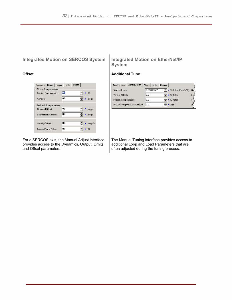
Offset Additional Tune
For a SERCOS axis, the Manual Adjust interface provides access to the Dynamics, Output, Limits and Offset parameters.
The Manual Tuning interface provides access to additional Loop and Load Parameters that are often adjusted during the tuning process.
33 | Integrated Motion on SERCOS and EtherNet/IP - Analysis and Comparison
Integrated Motion on SERCOS System Integrated Motion on EtherNet/IP System
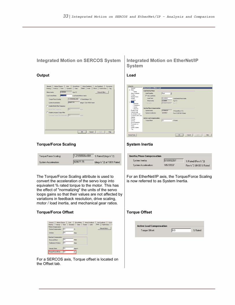
Output Load
Torque/Force Scaling System Inertia
The Torque/Force Scaling attribute is used to convert the acceleration of the servo loop into equivalent % rated torque to the motor. This has the effect of "normalizing" the units of the servo loops gains so that their values are not affected by variations in feedback resolution, drive scaling, motor / load inertia, and mechanical gear ratios.
For an EtherNet/IP axis, the Torque/Force Scaling is now referred to as System Inertia.
Torque/Force Offset Torque Offset
For a SERCOS axis, Torque offset is located on the Offset tab.

34 | Integrated Motion on SERCOS and EtherNet/IP - Analysis and Comparison
6BAdditional Axis Property Equivalents
Integrated Motion on SERCOS System Integrated Motion on EtherNet/IP System
Torque Control Compensation Features
A number of important compensation features are included in the torque control loop to help overcome physical effects that are inherit to most mechanical systems.
Offset – Backlash Compensation Backlash Compensation
Backlash Compensation is used to stabilize the control loop for applications with high load inertia ratios and mechanical backlash.
Output – Low Pass & Notch Filters Compliance Compensation
The Lead-Lag filter can be used in the lead configuration to boost velocity or acceleration loop bandwidth, or in the lag configuration to compensate the high frequency gain boost associated with compliant load mechanics.
NOTE: The Lead-Lag Filter is a new feature added for EtherNet/IP axes only.

35 | Integrated Motion on SERCOS and EtherNet/IP - Analysis and Comparison
Integrated Motion on SERCOS System Integrated Motion on EtherNet/IP System
Offset – Friction Compensation Friction Compensation
Friction Compensation applies a compensating directional torque or force to the motor to overcome the effects of friction in the mechanical system, thus minimizing the amount of control effort required.
Load Observer
For a SERCOS axis, the Load Observer feature does not exist.
Load Observer is another compensation feature that can be effective in compensating for mechanical backlash, mechanical compliance and various load disturbances.

36 | Integrated Motion on SERCOS and EtherNet/IP - Analysis and Comparison
Integrated Motion on SERCOS System Integrated Motion on EtherNet/IP System
Loop Gains & Limits
The loop gains between a SERCOS and Ethernet/IP axis are similar, however a few notable differences do exist.
Position Gains & Limits Position Loop

37 | Integrated Motion on SERCOS and EtherNet/IP - Analysis and Comparison
Integrated Motion on SERCOS System Integrated Motion on EtherNet/IP System
Velocity Gains & Limits Velocity Loop
NOTE: For an EtherNet/IP axis, the Bipolar Velocity Limit does not exist. The ± limits must be set independently.
Acceleration Limits Acceleration Loop
NOTE: For an EtherNet/IP axis, the Bipolar Acceleration Limit does not exist. The Accel/Decel limits must be set independently.
38 | Integrated Motion on SERCOS and EtherNet/IP - Analysis and Comparison
Integrated Motion on SERCOS System Integrated Motion on EtherNet/IP System
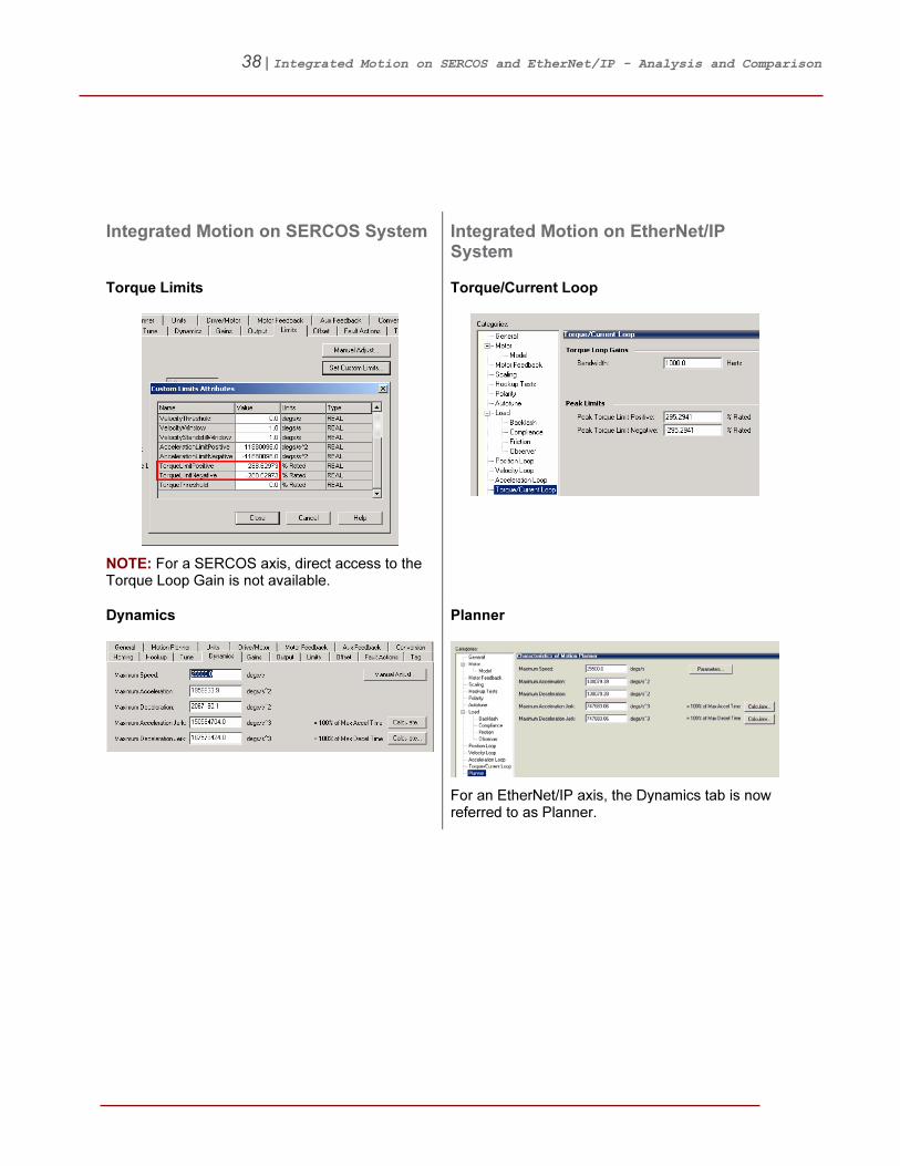
Torque Limits Torque/Current Loop
NOTE: For a SERCOS axis, direct access to the Torque Loop Gain is not available.
Dynamics Planner
For an EtherNet/IP axis, the Dynamics tab is now referred to as Planner.
39 | Integrated Motion on SERCOS and EtherNet/IP - Analysis and Comparison
Integrated Motion on SERCOS System Integrated Motion on EtherNet/IP System
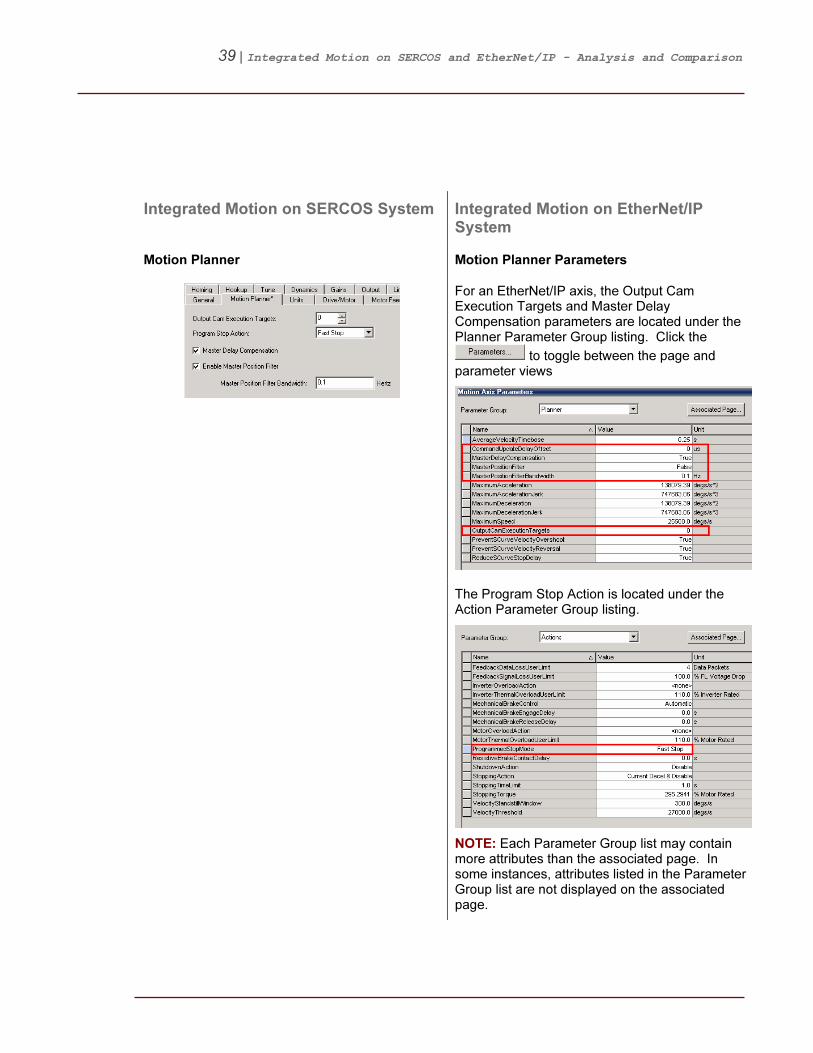
Motion Planner Motion Planner Parameters
For an EtherNet/IP axis, the Output Cam Execution Targets and Master Delay Compensation parameters are located under the Planner Parameter Group listing. Click the
to toggle between the page and parameter views
The Program Stop Action is located under the Action Parameter Group listing.
NOTE: Each Parameter Group list may contain more attributes than the associated page. In some instances, attributes listed in the Parameter Group list are not displayed on the associated page.
40 | Integrated Motion on SERCOS and EtherNet/IP - Analysis and Comparison
Integrated Motion on SERCOS System Integrated Motion on EtherNet/IP System
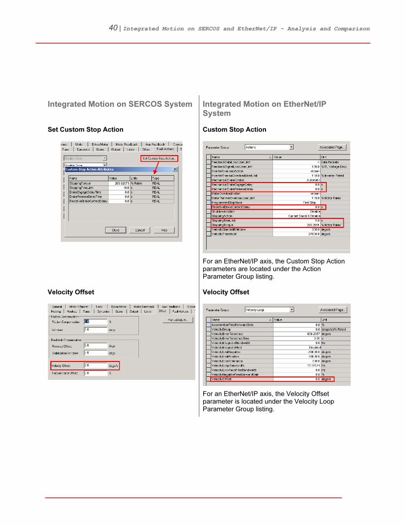
Set Custom Stop Action Custom Stop Action
For an EtherNet/IP axis, the Custom Stop Action parameters are located under the Action Parameter Group listing.
Velocity Offset Velocity Offset
For an EtherNet/IP axis, the Velocity Offset parameter is located under the Velocity Loop Parameter Group listing.
41 | Integrated Motion on SERCOS and EtherNet/IP - Analysis and Comparison
7BDiagnostics
The following section will highlight some of the diagnostic capabilities unique to Integrated Motion on EtherNet/IP systems.
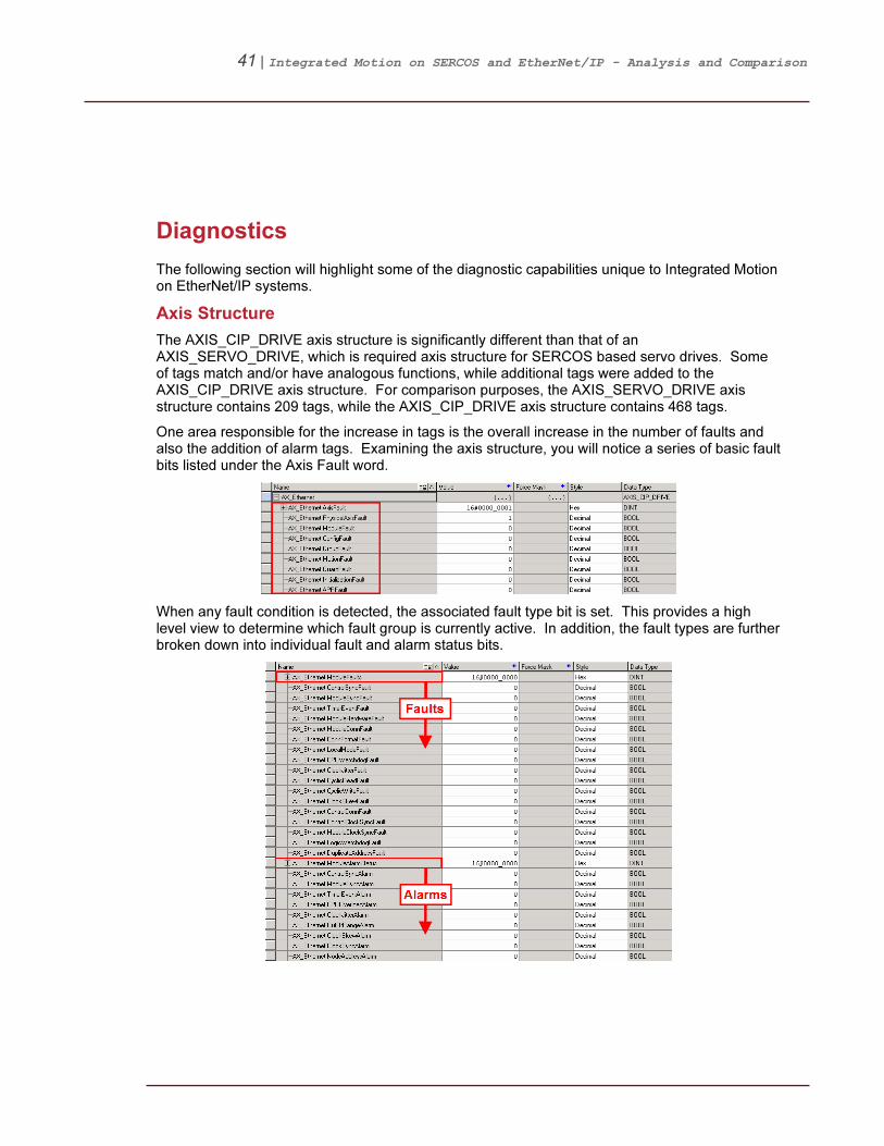
10BAxis Structure
The AXIS_CIP_DRIVE axis structure is significantly different than that of an AXIS_SERVO_DRIVE, which is required axis structure for SERCOS based servo drives. Some of tags match and/or have analogous functions, while additional tags were added to the AXIS_CIP_DRIVE axis structure. For comparison purposes, the AXIS_SERVO_DRIVE axis structure contains 209 tags, while the AXIS_CIP_DRIVE axis structure contains 468 tags.
One area responsible for the increase in tags is the overall increase in the number of faults and also the addition of alarm tags. Examining the axis structure, you will notice a series of basic fault bits listed under the Axis Fault word.
When any fault condition is detected, the associated fault type bit is set. This provides a high level view to determine which fault group is currently active. In addition, the fault types are further broken down into individual fault and alarm status bits.

42 | Integrated Motion on SERCOS and EtherNet/IP - Analysis and Comparison
11BFaults & Alarms Log
The Faults & Alarms Log displays current status of both faults and alarms are logged by the controller for each individual axis.
The display is read-only except for the ability to clear each of the logs (Faults, Alarms and Resets) independently. For example the alarm log can be cleared while maintaining the Faults and Resets logs. When online, select the Show checkboxes to toggle between showing and hiding the specified group of entries and use the Clear Log button clear the selected log.
NOTE: Only the last 25 faults and alarms are displayed.

43 | Integrated Motion on SERCOS and EtherNet/IP - Analysis and Comparison
12BKinetix 6500 Embedded Webpage
The Kinetix 6500 Embedded Webpage contains a number of advanced diagnostic and troubleshooting tools. The embedded webpage is launched by entering the desired drives IP address into the address bar of a web browser like Internet Explorer.
The Home page will be initially displayed.
The Home page displays basic drive information like MAC and IP addresses, firmware revision, and catalog number information. In addition, the Home page indicated the current status of the drive.

44 | Integrated Motion on SERCOS and EtherNet/IP - Analysis and Comparison
The Drive Indicators page displays the active 4-Character Display and Status (LED) Indicators on the front of the drive control module. The Status Indicators include descriptions of their current state.

45 | Integrated Motion on SERCOS and EtherNet/IP - Analysis and Comparison
The Oscilloscope page provides the user with the ability to capture waveforms directly from the drive at periods up to 1-servo update. This means information can be captured from the drive that was previously unavailable to user, providing an added level diagnostic capability.
The user can select up to 4 waveforms to capture, with the ability to select the number of samples, update period and trigger source.
NOTE: The Oscilloscope feature does NOT impact the performance of the drive.
46 | Integrated Motion on SERCOS and EtherNet/IP - Analysis and Comparison
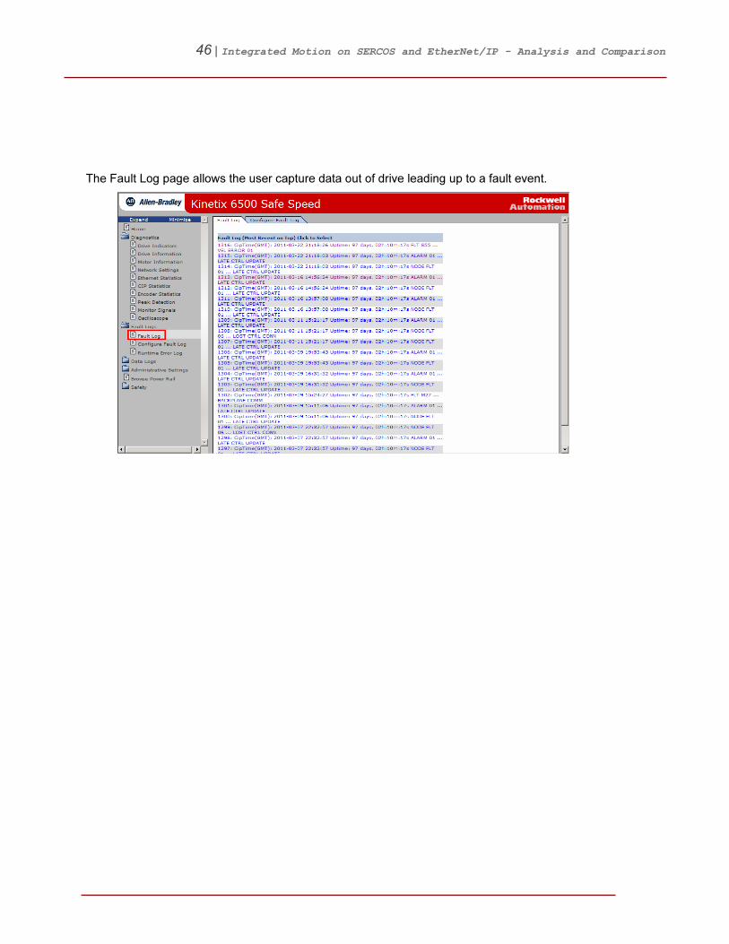
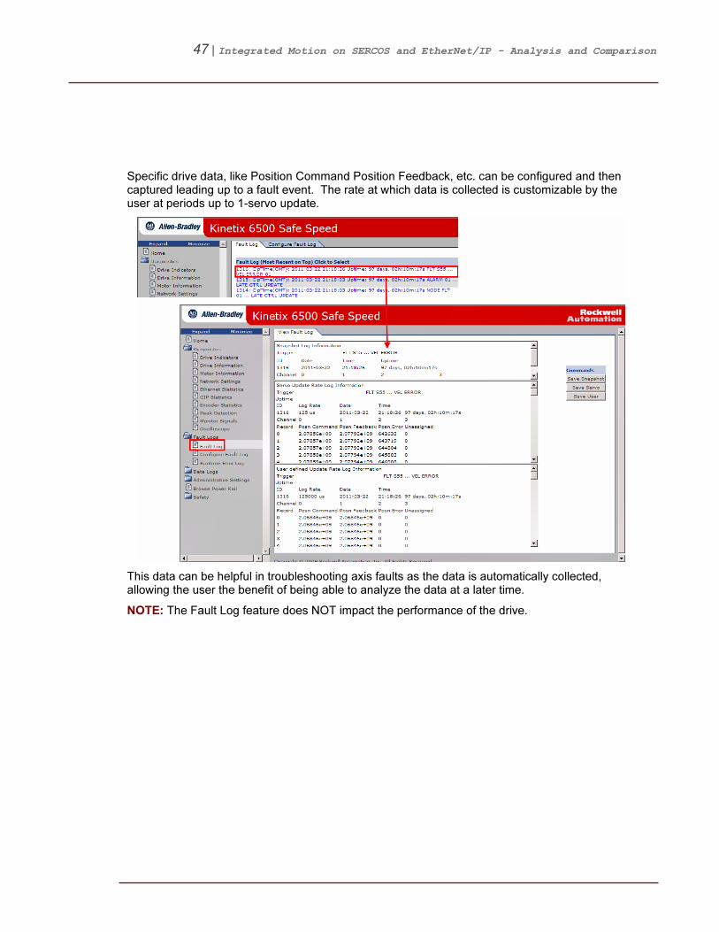
The Fault Log page allows the user capture data out of drive leading up to a fault event.
47 | Integrated Motion on SERCOS and EtherNet/IP - Analysis and Comparison
Specific drive data, like Position Command Position Feedback, etc. can be configured and then captured leading up to a fault event. The rate at which data is collected is customizable by the user at periods up to 1-servo update.
This data can be helpful in troubleshooting axis faults as the data is automatically collected, allowing the user the benefit of being able to analyze the data at a later time.
NOTE: The Fault Log feature does NOT impact the performance of the drive.

48 | Integrated Motion on SERCOS and EtherNet/IP - Analysis and Comparison
8BSupplemental Information
13BAppendix A – Ethernet Communication Module Drive Limits
The following examples will help illustrate the number of drives that can be connected to each Ethernet communication module. The limits are a combination of loop configuration and available CIP and TCP connections. Each drive requires 1-CIP and 1-TCP connection.
1756-EN2T / EN2F / EN2TR: EN2x modules are limited to 8 position configured drives. However, EN2x modules can support a total of 128 non-position configured drives. The non-position configured limit is based on the number of available CIP and TCP connections. EN2x modules support up to 256-CIP and 128-TCP connections.
Examples:
1. 008 position | 120 non-position
2. 000 position | 128 non-position
3. 00X position | (128 - X) non-position � X ≤ 8
1756-EN3TR: EN3x modules are limited to 128 drives regardless the number of position configured drives. The number of drives is based on the number of available CIP and TCP connections. EN3x modules support up to 256-CIP and 128-TCP connections.
Examples:
1. 128 position | 000 non-position
2. 000 position | 128 non-position
3. 00X position | (128 - X) non-position � X ≤ 128
NOTE: The numbers listed above do not include other EtherNet/IP devices. As additional devices
are added to the network, CIP and TCP connections will be consumed which may limit the total
number of connected drives.

49 | Integrated Motion on SERCOS and EtherNet/IP - Analysis and Comparison
14BAppendix B – Kinetix 6500 IP Address Assignment
The Ethernet IP Address for the Kinetix 6500 can be assigned as follows:
Isolated: The easiest way is by setting (001…255) the thumbwheel switches on the front of the Integrates Axis Module (IAM).
192.168.1. Static: For drive firmware v1, a static IP Address which can be set through RSLinx
®. You will
need to set the thumbwheels to non-valid value (000, 256…999). For drive firmware v2 or higher, a static IP address can be assigned via the BOOTP-DHCP server. See the dynamic option below. Dynamic: For drive firmware v2 or higher, when the thumbwheels are set to a non-valid address (000, 256…999) out of the box, the drives will be placed into BOOTP mode. An IP Address can then be assigned via the BOOTP-DHCP server. At this point the drives can also be placed into DHCP or a static IP Address can be assigned via RSLinx
®.
DHCP Persistence: DHCP persistence allows you to reserve and pre-assign an IP address from an IP address pool to a specific switch port, so that a drive connected to that switch port always receives the same IP address, regardless of its MAC address. DHCP Persistence allows the static address to be assigned to the port on the switch. Because of this, the end device does not need to be manually configured for a static IP address. There are two typical use cases for implementing DHCP persistence: replacement of a failed device in the field, and setting up a new ‘out of the box’ device.
In a typical EtherNet/IP system, the user should configure the switch first for DHCP Persistence IP allocation. Once this is complete, all devices that have DHCP/BOOTP enabled should be configured properly and communicating on the network.
50 | Integrated Motion on SERCOS and EtherNet/IP - Analysis and Comparison
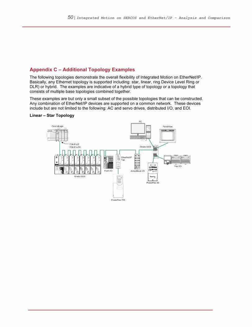
15BAppendix C – Additional Topology Examples
The following topologies demonstrate the overall flexibility of Integrated Motion on EtherNet/IP. Basically, any Ethernet topology is supported including: star, linear, ring Device Level Ring or DLR) or hybrid. The examples are indicative of a hybrid type of topology or a topology that consists of multiple base topologies combined together.
These examples are but only a small subset of the possible topologies that can be constructed. Any combination of EtherNet/IP devices are supported on a common network. These devices include but are not limited to the following: AC and servo drives, distributed I/O, and EOI.
Linear – Star Topology
51 | Integrated Motion on SERCOS and EtherNet/IP - Analysis and Comparison
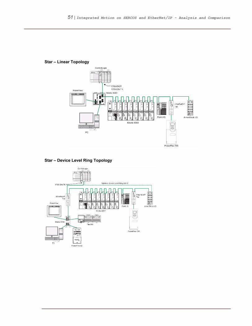
Star – Linear Topology
Star – Device Level Ring Topology

52 | Integrated Motion on SERCOS and EtherNet/IP - Analysis and Comparison
16BAppendix D – Drive Parameters Cyclic Read/Write List
SERCOS Axis (Real Time Axis Info)
Cyclic Read Parameters
EtherNet/IP Axis Cyclic Read Parameters
EtherNet/IP Axis Cyclic Write Parameters
PositionCommand PositionFineCommand PositionTrim
PositionFeedback PositionReference VelocityTrim
AuxPositionFeedback PositionFeedback1 TorqueTrim
PositionError PositionError VelocityFeedforwardGain
PositionIntegratorError PositionIntegratorOutput AccerlationFeedforwardGain
VelocityCommand PositionLoopOutput PositionLoopBandwidth
VelocityFeedback VelocityFineCommand PositionIntegratorBandwidth
VelocityError VelocityFeedforwardCommand VelocityLoopBandwidth
VelocityIntegratorError VelocityReference VelocityIntegratorBandwidth
AccelerationCommand VelocityFeedback LoadObserverBandwidth
AccelerationFeedback VelocityError TorqueLimitPositive
MarkerDistance VelocityIntegratorOutput TorqueLimitNegative
TorqueCommand VelocityLoopOutput VelocityLowPassFilterBandwidth
TorqueFeedback AccelerationFeedforwardCommand TorqueLowPassFilterBandwidth
PositiveDynamicTorqueLimit AccelerationFeedback SystemInertia
NegativeDynamicTorqueLimit LoadObserverAccelerationEstimate
MotorCapacity LoadObserverTorqueEstimate
DriveCapacity TorqueReference
PowerCapacity TorqueReferenceFiltered
BusRegulatorCapacity TorqueReferenceLimited
MotorElectricalAngle CurrentCommand
TorqueLimitSource CurrentFeedback
DCBusVoltage FluxCurrentFeedback
OutputFrequency
OutputCurrent
OutputVoltage
OutputPower
DCBusVoltage
MotorCapacity
InverterCapacity
DigitalInputs

53 | Integrated Motion on SERCOS and EtherNet/IP - Analysis and Comparison
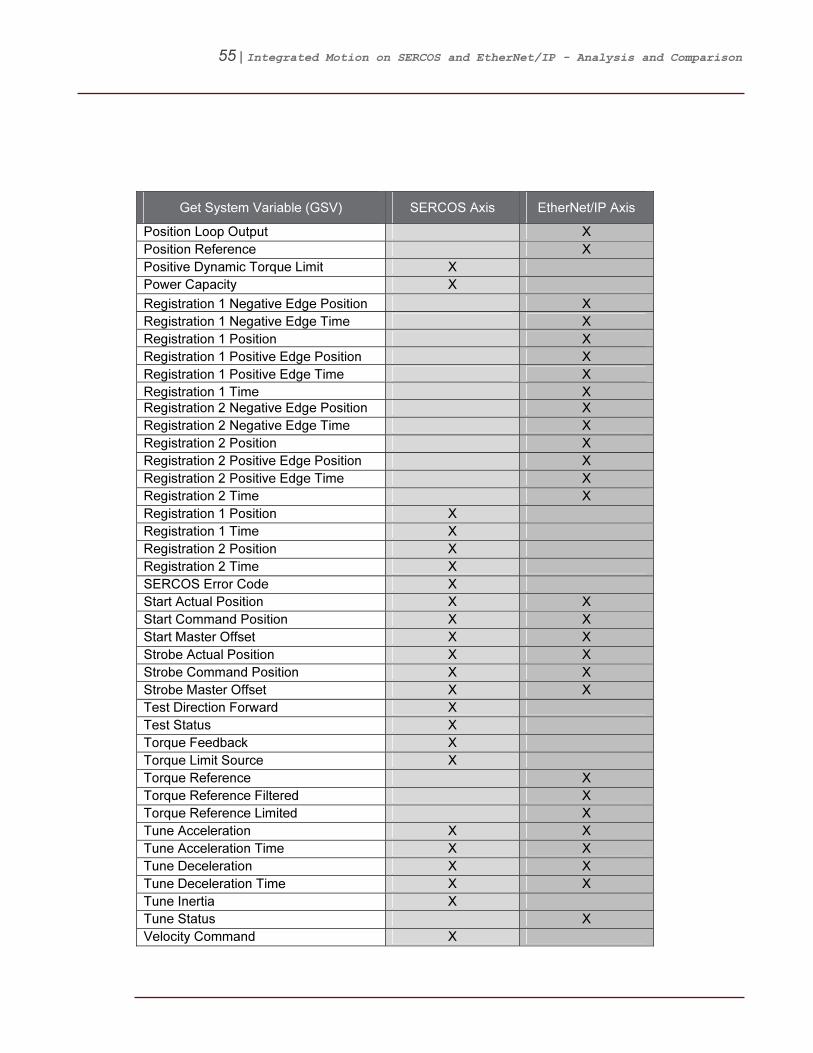
17BAppendix E – Available GSV & SSV Data
Get System Variable (GSV)
Get System Variable (GSV) SERCOS Axis EtherNet/IP Axis
Acceleration Feedforward Command X
Acceleration Command X
Acceleration Feedback X X
Actual Acceleration X
Actual Position X X
Actual Velocity X X
Analog Input 1 X
Analog Input 2 X
Attribute Error Code X X
Attribute Error ID X X
Aux Position Feedback X
Average Velocity X X
Axis Configuration X
Axis Control Bits X
Axis Event Bits X X
Axis Fault Bits X X
Axis Response Bits X
Axis Status Bits X X
Axis Features X
Bus Regulator Capacity X
CIP Axis Faults X
CIP Axis Faults RA X
CIP Axis IO Status X
CIP Axis IO Status RA X
CIP Axis State X
CIP Axis Status X
CIP Axis Status RA X
CIP Initialization Faults X
CIP Initialization Faults RA X
CIP Start Inhibit X
CIP Start Inhibit RA X
Command Acceleration X X
Command Position X X
Command Velocity X X
Control Method X
Current Command X
DC Bus Voltage X
Drive Capacity X

54 | Integrated Motion on SERCOS and EtherNet/IP - Analysis and Comparison
Get System Variable (GSV) SERCOS Axis EtherNet/IP Axis
Drive Fault Bits X
Drive Status Bits X
Drive Warning Bits X
Guard Faults X
Guard Status X
Hookup Test Commutation Offset X
Hookup Test Commutation Polarity X
Hookup Test Feedback 1 Direction X
Hookup Test Feedback 2 Direction X
Hookup Test Status X
Interpolated Actual Position X X
Interpolated Command Position X X
Inverter Capacity X
Marker Distance X X
Master Offset X X
Module Alarm Bits X
Module Fault Bits X X
Module Status Bits X
Motor Capacity X X
Motion Alarm Bits X
Motion Fault Bits X
Motion Status Bits X
Motor Electrical Angle X
Motor Test Counter EMF X
Motor Test Inductance X
Motor Test Resistance X
Motor Test Status X
Motor Unit X
Negative Dynamic Torque Limit X
Output Cam Lock Status X X
Output Cam Pending Status X X
Output Cam Status X X
Output Cam Transition Status X X
Output Current X
Output Power X
Output Voltage X
Position Command X
Position Error X X
Position Feedback X
Position Integrator Error X
Position Integrator Output X
55 | Integrated Motion on SERCOS and EtherNet/IP - Analysis and Comparison
Get System Variable (GSV) SERCOS Axis EtherNet/IP Axis
Position Loop Output X
Position Reference X
Positive Dynamic Torque Limit X
Power Capacity X
Registration 1 Negative Edge Position X
Registration 1 Negative Edge Time X
Registration 1 Position X
Registration 1 Positive Edge Position X
Registration 1 Positive Edge Time X
Registration 1 Time X
Registration 2 Negative Edge Position X
Registration 2 Negative Edge Time X
Registration 2 Position X
Registration 2 Positive Edge Position X
Registration 2 Positive Edge Time X
Registration 2 Time X
Registration 1 Position X
Registration 1 Time X
Registration 2 Position X
Registration 2 Time X
SERCOS Error Code X
Start Actual Position X X
Start Command Position X X
Start Master Offset X X
Strobe Actual Position X X
Strobe Command Position X X
Strobe Master Offset X X
Test Direction Forward X
Test Status X
Torque Feedback X
Torque Limit Source X
Torque Reference X
Torque Reference Filtered X
Torque Reference Limited X
Tune Acceleration X X
Tune Acceleration Time X X
Tune Deceleration X X
Tune Deceleration Time X X
Tune Inertia X
Tune Status X
Velocity Command X
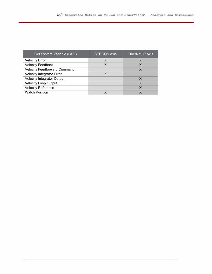
56 | Integrated Motion on SERCOS and EtherNet/IP - Analysis and Comparison
Get System Variable (GSV) SERCOS Axis EtherNet/IP Axis
Velocity Error X X
Velocity Feedback X X
Velocity Feedforward Command X
Velocity Integrator Error X
Velocity Integrator Output X
Velocity Loop Output X
Velocity Reference X
Watch Position X X
57 | Integrated Motion on SERCOS and EtherNet/IP - Analysis and Comparison
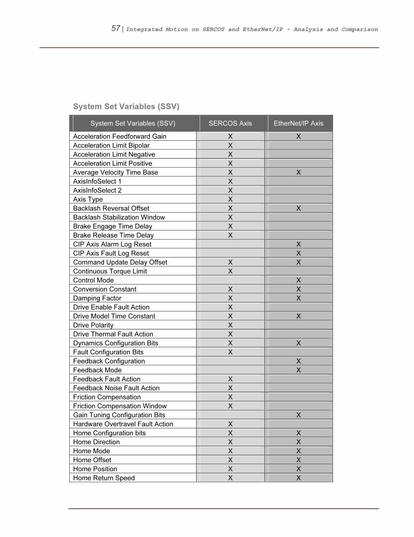
System Set Variables (SSV)
System Set Variables (SSV) SERCOS Axis EtherNet/IP Axis
Acceleration Feedforward Gain X X
Acceleration Limit Bipolar X
Acceleration Limit Negative X
Acceleration Limit Positive X
Average Velocity Time Base X X
AxisInfoSelect 1 X
AxisInfoSelect 2 X
Axis Type X
Backlash Reversal Offset X X
Backlash Stabilization Window X
Brake Engage Time Delay X
Brake Release Time Delay X
CIP Axis Alarm Log Reset X
CIP Axis Fault Log Reset X
Command Update Delay Offset X X
Continuous Torque Limit X
Control Mode X
Conversion Constant X X
Damping Factor X X
Drive Enable Fault Action X
Drive Model Time Constant X X
Drive Polarity X
Drive Thermal Fault Action X
Dynamics Configuration Bits X X
Fault Configuration Bits X
Feedback Configuration X
Feedback Mode X
Feedback Fault Action X
Feedback Noise Fault Action X
Friction Compensation X
Friction Compensation Window X
Gain Tuning Configuration Bits X
Hardware Overtravel Fault Action X
Home Configuration bits X X
Home Direction X X
Home Mode X X
Home Offset X X
Home Position X X
Home Return Speed X X

58 | Integrated Motion on SERCOS and EtherNet/IP - Analysis and Comparison
System Set Variables (SSV) SERCOS Axis EtherNet/IP Axis
Home Sequence X X
Home Speed X X
Home Torque Level X
Hookup Test Distance X
Hookup Test Feedback Channel X
Inhibit Axis X X
Integrator Hold Enable X
Interpolation Time X X
Linear Motor Mass X
Load Inertia Ratio X X
Load Ratio X
Master Input Configuration Bits X X
Master Position Filter Bandwidth X X
Maximum Acceleration X X
Maximum Acceleration Jerk X X
Maximum Deceleration X X
Maximum Deceleration Jerk X X
Maximum Negative Travel X
Maximum Positive Travel X
Maximum Speed X
Motion Polarity X
Motion Resolution X
Motor Inertia X
Motor Thermal Fault Action X
Output LP Filter Bandwidth X
Output Notch Filter Frequency X
Position Error Fault Action X
Position Error Tolerance X X
Position Integrator Bandwidth X
Position Integrator Control X
Position Integral Gain X
Position Lock Tolerance X X
Position Loop Bandwidth X
Position Proportional Gain X
Position Servo Bandwidth X
Position Trim X
Position Unwind X X
Programmed Stop Mode X X
Resistive Brake Contact Delay X
Rotary Axis X
Rotary Motor Inertia X

59 | Integrated Motion on SERCOS and EtherNet/IP - Analysis and Comparison
System Set Variables (SSV) SERCOS Axis EtherNet/IP Axis
Scaling Source X
Servo loop configuration X
Soft Overtravel Fault Action X
Soft Travel Limit Checking X
Soft Travel Limit Negative X
Soft Travel Limit Positive X
Stopping Action X
Stopping Time Limit X
Stopping Torque X X
System Bandwidth X
System Damping X
System Inertia X
Test Increment X
Torque Limit Bipolar X
Torque Limit Negative X X
Torque Limit Positive X X
Torque Offset X X
Torque Scaling X
Torque Threshold X
Torque Trim X
Travel Mode X
Travel Range
Tune Friction X
Tune Inertia Mass X
Tune Load Offset X
Tuning Configuration Bits X
Tuning Direction X
Tuning Select X
Tuning Speed X X
Tuning Torque X X
Tuning Travel Limits X X
Velocity Droop X
Velocity Feedforward Gain X X
Velocity Integral Gain X
Velocity Integrator Bandwidth X
Velocity Integrator Control X
Velocity Limit Bipolar X
Velocity Limit Negative X
Velocity Limit Positive X
Velocity Loop Bandwidth X
Velocity Offset X X

60 | Integrated Motion on SERCOS and EtherNet/IP - Analysis and Comparison
System Set Variables (SSV) SERCOS Axis EtherNet/IP Axis
Velocity Proportional Gain X
Velocity Servo Bandwidth X X
Velocity Standstill Window X X
Velocity Threshold X
Velocity Trim X
Velocity Window X
61 | Integrated Motion on SERCOS and EtherNet/IP - Analysis and Comparison
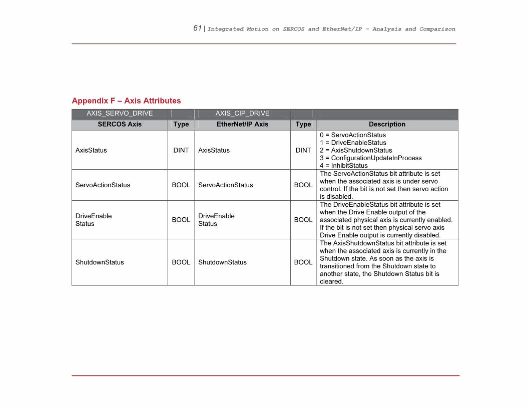
18BAppendix F – Axis Attributes
AXIS_SERVO_DRIVE AXIS_CIP_DRIVE
SERCOS Axis Type EtherNet/IP Axis Type Description
AxisStatus DINT AxisStatus DINT
0 = ServoActionStatus 1 = DriveEnableStatus 2 = AxisShutdownStatus 3 = ConfigurationUpdateInProcess 4 = InhibitStatus
ServoActionStatus BOOL ServoActionStatus BOOL
The ServoActionStatus bit attribute is set when the associated axis is under servo control. If the bit is not set then servo action is disabled.
DriveEnable Status
BOOL DriveEnable Status
BOOL
The DriveEnableStatus bit attribute is set when the Drive Enable output of the associated physical axis is currently enabled. If the bit is not set then physical servo axis Drive Enable output is currently disabled.
ShutdownStatus BOOL ShutdownStatus BOOL
The AxisShutdownStatus bit attribute is set when the associated axis is currently in the Shutdown state. As soon as the axis is transitioned from the Shutdown state to another state, the Shutdown Status bit is cleared.
62 | Integrated Motion on SERCOS and EtherNet/IP - Analysis and Comparison
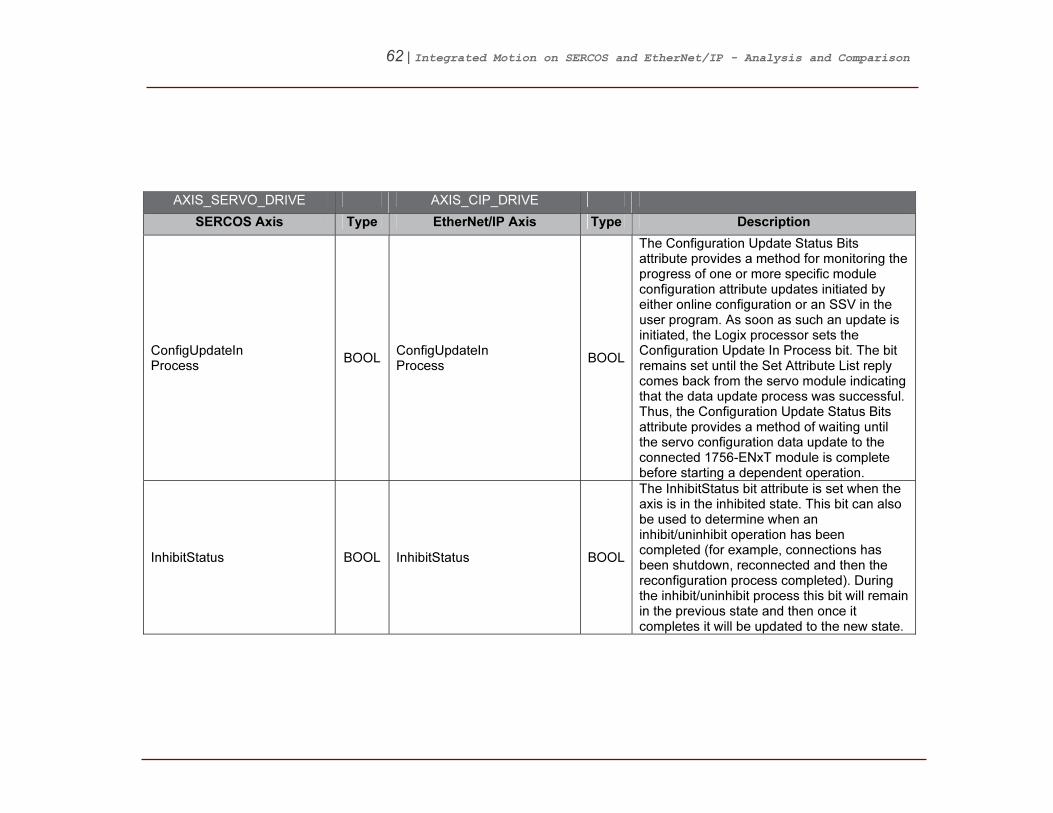
AXIS_SERVO_DRIVE AXIS_CIP_DRIVE
SERCOS Axis Type EtherNet/IP Axis Type Description
ConfigUpdateIn Process
BOOL ConfigUpdateIn Process
BOOL
The Configuration Update Status Bits attribute provides a method for monitoring the progress of one or more specific module configuration attribute updates initiated by either online configuration or an SSV in the user program. As soon as such an update is initiated, the Logix processor sets the Configuration Update In Process bit. The bit remains set until the Set Attribute List reply comes back from the servo module indicating that the data update process was successful. Thus, the Configuration Update Status Bits attribute provides a method of waiting until the servo configuration data update to the connected 1756-ENxT module is complete before starting a dependent operation.
InhibitStatus BOOL InhibitStatus BOOL
The InhibitStatus bit attribute is set when the axis is in the inhibited state. This bit can also be used to determine when an inhibit/uninhibit operation has been completed (for example, connections has been shutdown, reconnected and then the reconfiguration process completed). During the inhibit/uninhibit process this bit will remain in the previous state and then once it completes it will be updated to the new state.
63 | Integrated Motion on SERCOS and EtherNet/IP - Analysis and Comparison
AXIS_SERVO_DRIVE AXIS_CIP_DRIVE
SERCOS Axis Type EtherNet/IP Axis Type Description
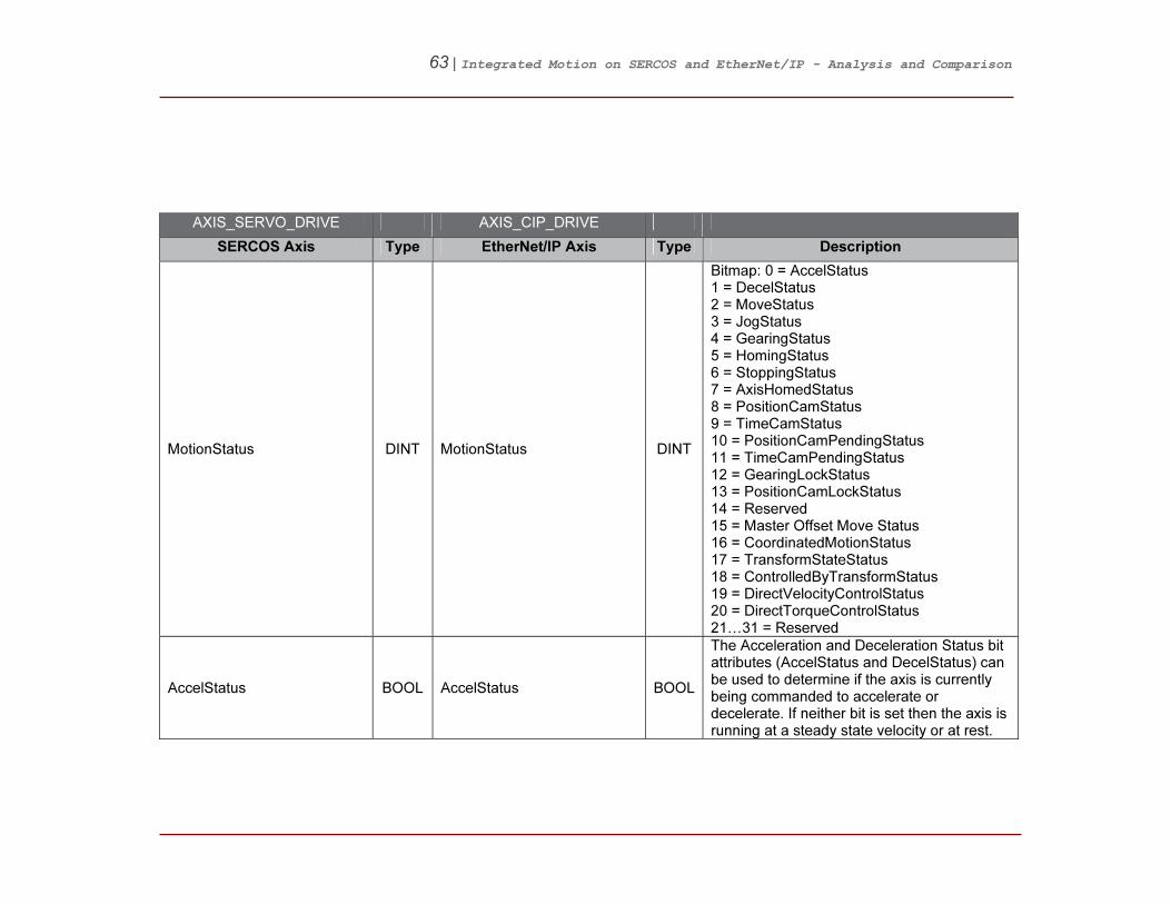
MotionStatus DINT MotionStatus DINT
Bitmap: 0 = AccelStatus 1 = DecelStatus 2 = MoveStatus 3 = JogStatus 4 = GearingStatus 5 = HomingStatus 6 = StoppingStatus 7 = AxisHomedStatus 8 = PositionCamStatus 9 = TimeCamStatus 10 = PositionCamPendingStatus 11 = TimeCamPendingStatus 12 = GearingLockStatus 13 = PositionCamLockStatus 14 = Reserved 15 = Master Offset Move Status 16 = CoordinatedMotionStatus 17 = TransformStateStatus 18 = ControlledByTransformStatus 19 = DirectVelocityControlStatus 20 = DirectTorqueControlStatus 21…31 = Reserved
AccelStatus BOOL AccelStatus BOOL
The Acceleration and Deceleration Status bit attributes (AccelStatus and DecelStatus) can be used to determine if the axis is currently being commanded to accelerate or decelerate. If neither bit is set then the axis is running at a steady state velocity or at rest.

64 | Integrated Motion on SERCOS and EtherNet/IP - Analysis and Comparison
AXIS_SERVO_DRIVE AXIS_CIP_DRIVE
SERCOS Axis Type EtherNet/IP Axis Type Description
DecelStatus BOOL DecelStatus BOOL
The Acceleration and Deceleration Status bit attributes (AccelStatus and DecelStatus) can be used to determine if the axis is currently being commanded to accelerate or decelerate. If neither bit is set then the axis is running at steady state velocity or at rest.
MoveStatus BOOL MoveStatus BOOL
The Acceleration and Deceleration Status bit attributes (AccelStatus and DecelStatus) can be used to determine if the axis is currently being commanded to accelerate or decelerate. If neither bit is set then the axis is running at steady state velocity or at rest.
JogStatus BOOL JogStatus BOOL
The JogStatus bit attribute is set if a Jog motion, profile is currently in progress. As soon as the Jog is complete or superseded by some other motion operation, the JogStatus bit is cleared.
GearingStatus BOOL GearingStatus BOOL
The GearingStatus bit attribute is set if the axis is currently Gearing to another axis. As soon as the gearing operation is stopped or superseded by some other motion operation, the GearStatus bit is cleared.
HomingStatus BOOL HomingStatus BOOL
The HomingStatus bit attribute is set if a Home motion profile is currently in progress. As soon as the Home is complete or superseded by some other motion operation, the HomeStatus bit is cleared.

65 | Integrated Motion on SERCOS and EtherNet/IP - Analysis and Comparison
AXIS_SERVO_DRIVE AXIS_CIP_DRIVE
SERCOS Axis Type EtherNet/IP Axis Type Description
StoppingStatus BOOL StoppingStatus BOOL
The StoppingStatus bit attribute is set if there is a stopping process currently in progress. As soon as the stopping process is complete, the Stopping Status bit is cleared. The stopping process is used to stop an axis (initiated by an MAS, MGS, MGPS, Stop Planner fault action, or mode change). This bit is no longer associated with the gearing Clutch bit (MAG with Clutch selected), which for I4B has been explicitly named the GearingLockStatus bit.

66 | Integrated Motion on SERCOS and EtherNet/IP - Analysis and Comparison
AXIS_SERVO_DRIVE AXIS_CIP_DRIVE
SERCOS Axis Type EtherNet/IP Axis Type Description
AxisHomedStatus BOOL AxisHomedStatus BOOL
The HomedStatus bit attribute is cleared at power up or reconnection. The bit is set to 1 by the MAH instruction upon successful completion of the configured homing sequence. This bit would be later cleared if the axis entered the shutdown state. The HomedStatus bit is set by the MAH instruction upon successful completion of the configured homing sequence. This bit indicates that an absolute machine reference position has been established. When this bit is set, operations that require a machine reference, such as Software Overtravel checking can be meaningfully enabled. The HomedStatus bit is cleared under the following conditions. 1. Download, Control power cycle, or Reconnection with Incremental Feedback device. 2. Absolute Position Recovery (APR) fails with Absolute Feedback device. 3. Feedback Integrity bit is cleared by CIP Motion drive. The HomedStatus bit is directly used by the control system to qualify the Software Overtravel checking function. Thus, if the HomedStatus bit is clear, Soft Overtravel checking will not occur even if the Soft Overtravel Checking bit is set.

67 | Integrated Motion on SERCOS and EtherNet/IP - Analysis and Comparison
AXIS_SERVO_DRIVE AXIS_CIP_DRIVE
SERCOS Axis Type EtherNet/IP Axis Type Description
PositionCam Status
BOOL PositionCam Status
BOOL
The PositionCamStatus bit attribute is set if a Position Cam motion, profile is currently in progress. As soon as the Position Cam is complete or superseded by some other motion operation, the PositionCamStatus bit is cleared.
TimeCamStatus BOOL TimeCamStatus BOOL
The TimeCamStatus bit attribute is set if a Time Cam motion, profile is currently in progress. As soon as the Time Cam is complete or superseded by some other motion operation, the TimeCamStatus bit is cleared.
PositionCam PendingStatus
BOOL PositionCam PendingStatus
BOOL
The PositionCamPendingStatus bit attribute is set if a Position Cam motion, profile is currently pending the completion of a currently executing cam profile. This would be initiated by executing an MAPC instruction with Pending execution selected. As soon as the current position cam profile completes, initiating the start of the pending cam profile, the PositionCamPending Status bit is cleared. This bit is also cleared if the position cam profile completes, or superseded by some other motion operation.
68 | Integrated Motion on SERCOS and EtherNet/IP - Analysis and Comparison
AXIS_SERVO_DRIVE AXIS_CIP_DRIVE
SERCOS Axis Type EtherNet/IP Axis Type Description
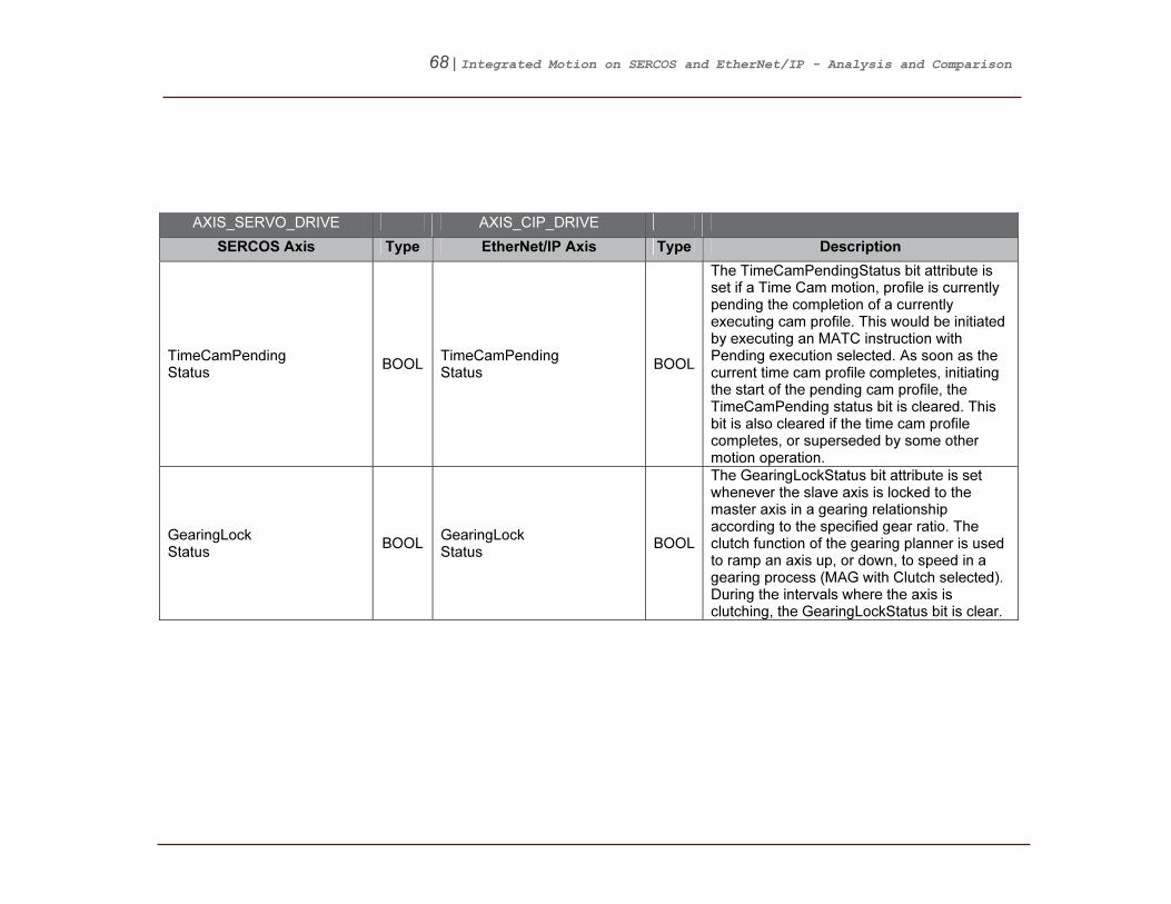
TimeCamPending Status
BOOL TimeCamPending Status
BOOL
The TimeCamPendingStatus bit attribute is set if a Time Cam motion, profile is currently pending the completion of a currently executing cam profile. This would be initiated by executing an MATC instruction with Pending execution selected. As soon as the current time cam profile completes, initiating the start of the pending cam profile, the TimeCamPending status bit is cleared. This bit is also cleared if the time cam profile completes, or superseded by some other motion operation.
GearingLock Status
BOOL GearingLock Status
BOOL
The GearingLockStatus bit attribute is set whenever the slave axis is locked to the master axis in a gearing relationship according to the specified gear ratio. The clutch function of the gearing planner is used to ramp an axis up, or down, to speed in a gearing process (MAG with Clutch selected). During the intervals where the axis is clutching, the GearingLockStatus bit is clear.

69 | Integrated Motion on SERCOS and EtherNet/IP - Analysis and Comparison
AXIS_SERVO_DRIVE AXIS_CIP_DRIVE
SERCOS Axis Type EtherNet/IP Axis Type Description
PositionCamLock Status
BOOL PositionCamLock Status
BOOL
The PositionCamLockStatus bit attribute is set whenever the master axis satisfies the starting condition of a currently active Position Cam motion profile. The starting condition is established by the Start Control and Start Position parameters of the MAPC instruction. As soon as the current position cam profile completes, or is superseded by some other motion operation, the Position Cam Lock bit is cleared. In unidirectional master direction mode, the PositionCamLockStatus bit clears when moving in the wrong direction and sets when moving in the correct direction.
MasterOffsetMove Status
BOOL MasterOffsetMove Status
BOOL
The MasterOffsetMoveStatus bit attribute is set if a Master Offset Move motion, profile is currently in progress. As soon as the Master Offset Move is complete or superseded by some other motion operation, the MasterOffsetMoveStatus bit is cleared.
Coordinated MotionStatus
BOOL Coordinated MotionStatus
BOOL
The CoordinatedMotionStatus bit attribute is set if any coordinated motion, profile is currently active upon this axis. As soon as the Coordinated Motion is complete or stopped, the CoordinatedMotionStatus bit is cleared.
70 | Integrated Motion on SERCOS and EtherNet/IP - Analysis and Comparison
AXIS_SERVO_DRIVE AXIS_CIP_DRIVE
SERCOS Axis Type EtherNet/IP Axis Type Description
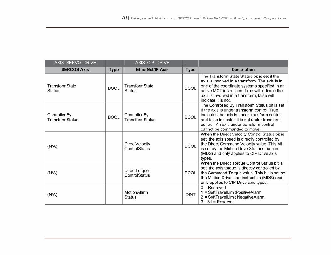
TransformState Status
BOOL TransformState Status
BOOL
The Transform State Status bit is set if the axis is involved in a transform. The axis is in one of the coordinate systems specified in an active MCT instruction. True will indicate the axis is involved in a transform, false will indicate it is not.
ControlledBy TransformStatus
BOOL ControlledBy TransformStatus
BOOL
The Controlled By Transform Status bit is set if the axis is under transform control. True indicates the axis is under transform control and false indicates it is not under transform control. An axis under transform control cannot be commanded to move.
(N/A) DirectVelocity ControlStatus
BOOL
When the Direct Velocity Control Status bit is set, the axis speed is directly controlled by the Direct Command Velocity value. This bit is set by the Motion Drive Start instruction (MDS) and only applies to CIP Drive axis types.
(N/A) DirectTorque ControlStatus
BOOL
When the Direct Torque Control Status bit is set, the axis torque is directly controlled by the Command Torque value. This bit is set by the Motion Drive start instruction (MDS) and only applies to CIP Drive axis types.
(N/A) MotionAlarm Status
DINT
0 = Reserved 1 = SoftTravelLimitPositiveAlarm 2 = SoftTravelLimit NegativeAlarm 3…31 = Reserved
71 | Integrated Motion on SERCOS and EtherNet/IP - Analysis and Comparison
AXIS_SERVO_DRIVE AXIS_CIP_DRIVE
SERCOS Axis Type EtherNet/IP Axis Type Description
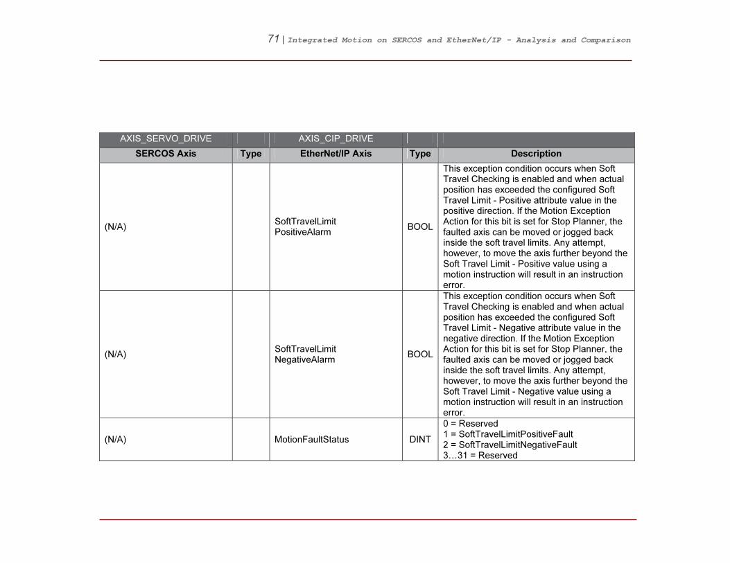
(N/A) SoftTravelLimit PositiveAlarm
BOOL
This exception condition occurs when Soft Travel Checking is enabled and when actual position has exceeded the configured Soft Travel Limit - Positive attribute value in the positive direction. If the Motion Exception Action for this bit is set for Stop Planner, the faulted axis can be moved or jogged back inside the soft travel limits. Any attempt, however, to move the axis further beyond the Soft Travel Limit - Positive value using a motion instruction will result in an instruction error.
(N/A) SoftTravelLimit NegativeAlarm
BOOL
This exception condition occurs when Soft Travel Checking is enabled and when actual position has exceeded the configured Soft Travel Limit - Negative attribute value in the negative direction. If the Motion Exception Action for this bit is set for Stop Planner, the faulted axis can be moved or jogged back inside the soft travel limits. Any attempt, however, to move the axis further beyond the Soft Travel Limit - Negative value using a motion instruction will result in an instruction error.
(N/A) MotionFaultStatus DINT
0 = Reserved 1 = SoftTravelLimitPositiveFault 2 = SoftTravelLimitNegativeFault 3…31 = Reserved

72 | Integrated Motion on SERCOS and EtherNet/IP - Analysis and Comparison
AXIS_SERVO_DRIVE AXIS_CIP_DRIVE
SERCOS Axis Type EtherNet/IP Axis Type Description
(N/A) SoftTravelLimit PositiveFault
BOOL
This exception condition occurs when Soft Travel Checking is enabled and when actual position has exceeded the configured Soft Travel Limit - Positive attribute value in the positive direction. If the Motion Exception Action for this bit is set for Stop Planner, the faulted axis can be moved or jogged back inside the soft travel limits. Any attempt, however, to move the axis further beyond the Soft Travel Limit - Positive value using a motion instruction will result in an instruction error.
(N/A) SoftTravelLimit NegativeFault
BOOL
This exception condition occurs when Soft Travel Checking is enabled and when actual position has exceeded the configured Soft Travel Limit - Negative attribute value in the negative direction. If the Motion Exception Action for this bit is set for Stop Planner, the faulted axis can be moved or jogged back inside the soft travel limits. Any attempt, however, to move the axis further beyond the Soft Travel Limit - Negative value using a motion instruction will result in an instruction error.
73 | Integrated Motion on SERCOS and EtherNet/IP - Analysis and Comparison
AXIS_SERVO_DRIVE AXIS_CIP_DRIVE
SERCOS Axis Type EtherNet/IP Axis Type Description
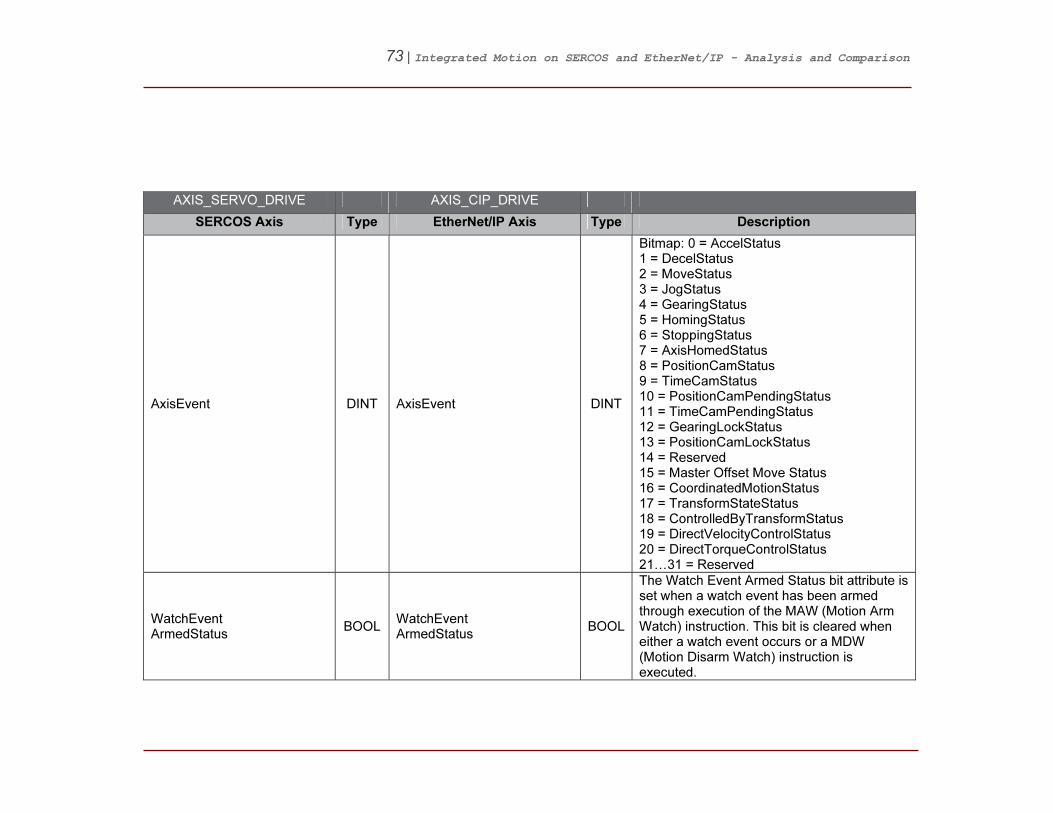
AxisEvent DINT AxisEvent DINT
Bitmap: 0 = AccelStatus 1 = DecelStatus 2 = MoveStatus 3 = JogStatus 4 = GearingStatus 5 = HomingStatus 6 = StoppingStatus 7 = AxisHomedStatus 8 = PositionCamStatus 9 = TimeCamStatus 10 = PositionCamPendingStatus 11 = TimeCamPendingStatus 12 = GearingLockStatus 13 = PositionCamLockStatus 14 = Reserved 15 = Master Offset Move Status 16 = CoordinatedMotionStatus 17 = TransformStateStatus 18 = ControlledByTransformStatus 19 = DirectVelocityControlStatus 20 = DirectTorqueControlStatus 21…31 = Reserved
WatchEvent ArmedStatus
BOOL WatchEvent ArmedStatus
BOOL
The Watch Event Armed Status bit attribute is set when a watch event has been armed through execution of the MAW (Motion Arm Watch) instruction. This bit is cleared when either a watch event occurs or a MDW (Motion Disarm Watch) instruction is executed.

74 | Integrated Motion on SERCOS and EtherNet/IP - Analysis and Comparison
AXIS_SERVO_DRIVE AXIS_CIP_DRIVE
SERCOS Axis Type EtherNet/IP Axis Type Description
WatchEventStatus BOOL WatchEventStatus BOOL
The Watch Event Status bit attribute is set when a watch event has occurred. This bit is cleared when either another MAW (Motion Arm Watch) instruction or a MDW (Motion Disarm Watch) instruction is executed.
RegEvent1Armed Status
BOOL RegEvent1Armed Status
BOOL
The Registration 1 Event Armed Status bit attribute is set when a registration checking has been armed for registration input 1 through execution of the MAR (Motion Arm Registration) instruction. This bit is cleared when either a registration event occurs or a MDR (Motion Disarm Registration) instruction is executed for registration input 1.
RegEvent1Status BOOL RegEvent1Status BOOL
The Registration 1 Event Status bit attribute is set when a registration event has occurred on registration input 1. This bit is cleared when either another MAR (Motion Arm Registration) instruction or a MDR (Motion Disarm Registration) instruction is executed for registration input 1.
RegEvent2Armed Status
BOOL RegEvent2Armed Status
BOOL
The Registration 2 Event Armed Status bit attribute is set when a registration checking has been armed for registration input 2 through execution of the MAR (Motion Arm Registration) instruction. This bit is cleared when either a registration event occurs or a MDR (Motion Disarm Registration) instruction is executed for registration input 2.

75 | Integrated Motion on SERCOS and EtherNet/IP - Analysis and Comparison
AXIS_SERVO_DRIVE AXIS_CIP_DRIVE
SERCOS Axis Type EtherNet/IP Axis Type Description
RegEvent2Status BOOL RegEvent2Status BOOL
The Registration 2 Event Status bit attribute is set when a registration event has occurred on registration input 2. This bit is cleared when either another MAR (Motion Arm Registration) instruction or a MDR (Motion Disarm Registration) instruction is executed for registration input 2.
HomeEventArmed Status
BOOL HomeEventArmed Status
BOOL
The Home Event Armed Status bit attribute is set when a home event has been armed and is used by the Home instruction (MAH) to manage various homing events that occur during the configured homing sequence. This bit is cleared when a home event occurs.
HomeEventStatus BOOL HomeEventStatus BOOL
The Home Event Status bit attribute is set when a home event has occurred and is used by the Home instruction (MAH) to manage various homing events that occur during the configured homing sequence. This bit is cleared when another MAH (Motion Axis Home) instruction is executed.

76 | Integrated Motion on SERCOS and EtherNet/IP - Analysis and Comparison
AXIS_SERVO_DRIVE AXIS_CIP_DRIVE
SERCOS Axis Type EtherNet/IP Axis Type Description
OutputCamStatus DINT OutputCamStatus DINT
The Output Cam Status bit is set when an Output Cam has been initiated. The Output Cam Status bit is reset when the cam position moves beyond the cam start or cam end position in Once execution mode with no Output Cam pending or when the Output Cam is terminated by a MDOC instruction. This attributes and all the output cam status words are bit patterns where each bit refers to an output cam target. For example, bit 0 is output cam target 0 and so on. This is true of all the output cam status words. Each of these bits corresponds to an output cam target.
OutputCam PendingStatus
DINT OutputCam PendingStatus
DINT
The Output Cam Pending Status bit is set if an Output Cam is currently pending the completion of another Output Cam. This would be initiated by executing an MAOC instruction with Pending execution selected. As soon as this output cam is armed, being triggered when the currently executing Output Cam has completed, the Output Cam Pending bit is cleared. This bit is also cleared if the Output Cam is terminated by a MDOC instruction.

77 | Integrated Motion on SERCOS and EtherNet/IP - Analysis and Comparison
AXIS_SERVO_DRIVE AXIS_CIP_DRIVE
SERCOS Axis Type EtherNet/IP Axis Type Description
OutputCamLock Status
DINT OutputCamLock Status
DINT
The Output Cam Lock Status bit is set when an Output Cam has been armed. This would be initiated by executing an MAOC instruction with Immediate execution selected, when a pending output cam changes to armed, or when the axis approaches or passes through the specified axis arm position. As soon as this output cam current position moves beyond the cam start or cam stop position, the Output Cam Lock bit is cleared. This bit is also cleared if the Output Cam is terminated by a MDOC instruction.
OutputCam TransitionStatus
DINT OutputCam TransitionStatus
DINT
The Output Cam Transition Status bit is set when a transition between the currently armed and the pending Output Cam is in process. Therefore, each Output Cam controls a subset of Output Bits. The Output Cam Transition Status bit is reset, when the transition to the pending Output Cam is complete or when the Output Cam is terminated by a MDOC instruction.
78 | Integrated Motion on SERCOS and EtherNet/IP - Analysis and Comparison
AXIS_SERVO_DRIVE AXIS_CIP_DRIVE
SERCOS Axis Type EtherNet/IP Axis Type Description
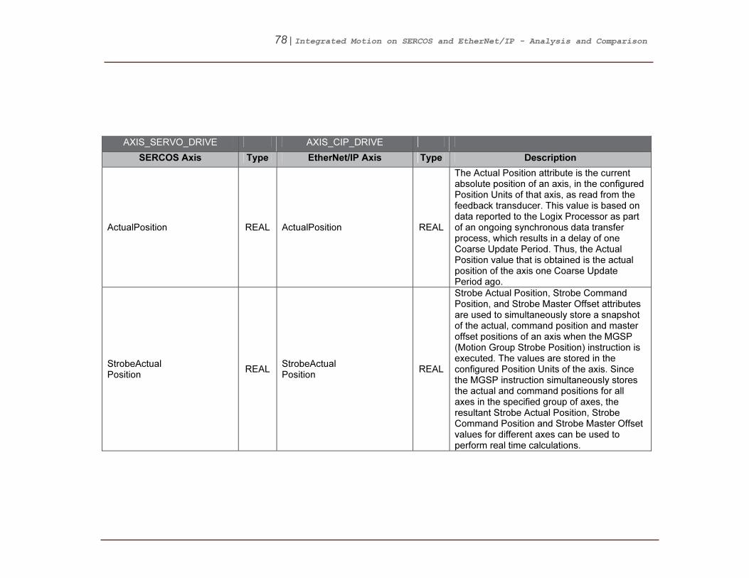
ActualPosition REAL ActualPosition REAL
The Actual Position attribute is the current absolute position of an axis, in the configured Position Units of that axis, as read from the feedback transducer. This value is based on data reported to the Logix Processor as part of an ongoing synchronous data transfer process, which results in a delay of one Coarse Update Period. Thus, the Actual Position value that is obtained is the actual position of the axis one Coarse Update Period ago.
StrobeActual Position
REAL StrobeActual Position
REAL
Strobe Actual Position, Strobe Command Position, and Strobe Master Offset attributes are used to simultaneously store a snapshot of the actual, command position and master offset positions of an axis when the MGSP (Motion Group Strobe Position) instruction is executed. The values are stored in the configured Position Units of the axis. Since the MGSP instruction simultaneously stores the actual and command positions for all axes in the specified group of axes, the resultant Strobe Actual Position, Strobe Command Position and Strobe Master Offset values for different axes can be used to perform real time calculations.

79 | Integrated Motion on SERCOS and EtherNet/IP - Analysis and Comparison
AXIS_SERVO_DRIVE AXIS_CIP_DRIVE
SERCOS Axis Type EtherNet/IP Axis Type Description
StartActual Position
REAL StartActual Position
REAL
Whenever a new motion planner instruction starts for an axis (for example, using a MAM instruction), the value of the axis command position and actual position is stored at the precise instant the motion begins. These values are stored as the Start Command Position and Start Actual Position respectively in the configured Position Units of the axis. Start Positions are useful to correct for any motion occurring between the detection of an event and the action initiated by the event. For instance, in coil winding applications, Start Command Positions can be used in an expression to compensate for overshooting the end of the bobbin before the gearing direction is reversed. If you know the position of the coil when the gearing direction was supposed to change, and the position at which it actually changed (the Start Command Position), you can calculate the amount of overshoot, and use it to correct the position of the wire guide relative to the bobbin.

80 | Integrated Motion on SERCOS and EtherNet/IP - Analysis and Comparison
AXIS_SERVO_DRIVE AXIS_CIP_DRIVE
SERCOS Axis Type EtherNet/IP Axis Type Description
AverageVelocity REAL AverageVelocity REAL
The Average Velocity attribute is the current speed and direction of an axis in the configured Position Units per second of the axis. Unlike the Actual Velocity attribute value, it is calculated by averaging the actual velocity of the axis over the configured Average Velocity Timebase for that axis. Average velocity is a signed value with the sign indicating the direction the axis is currently moving. The resolution of the Average Velocity variable is determined by the current value of the Averaged Velocity Timebase parameter, and the configured Conversion Constant (feedback counts per Position Unit) for the axis. The Average Velocity Timebase determines the length over which the Average Velocity is computed. The Average Velocity Time base is the length of time over which the average is computed. The greater the Average Velocity Timebase value, the better the speed resolution, but the slower the response to changes in speed.

81 | Integrated Motion on SERCOS and EtherNet/IP - Analysis and Comparison
AXIS_SERVO_DRIVE AXIS_CIP_DRIVE
SERCOS Axis Type EtherNet/IP Axis Type Description
ActualVelocity REAL ActualVelocity REAL
The Actual Velocity attribute is the current instantaneously measured speed and direction of an axis, in the configured axis Position Units per second. It is calculated from the current increment to the actual position per coarse update interval. Actual Velocity is a signed floating-point value the sign (+ or -) depends on which direction the axis is currently moving. Its resolution does not depend on the Averaged Velocity Timebase, but rather on the conversion constant of the axis and the fact that the internal resolution limit on actual velocity is 1 feedback count per coarse update.
Actual Acceleration
REAL Actual Acceleration
REAL
The Actual Acceleration attribute is the current instantaneously measured acceleration of an axis in the configured axis Position Units per second per second. It is calculated as the current increment to the actual velocity per coarse update interval. Actual Acceleration is a signed floating-point value. Its resolution does not depend on the Averaged Velocity Timebase, but rather on the Conversion Constant of the axis and the fact that the internal resolution limit on Actual Velocity is 1 feedback count per Coarse Update Period^2.

82 | Integrated Motion on SERCOS and EtherNet/IP - Analysis and Comparison
AXIS_SERVO_DRIVE AXIS_CIP_DRIVE
SERCOS Axis Type EtherNet/IP Axis Type Description
WatchPosition REAL WatchPosition REAL
The Watch Position attribute is the current set-point position of an axis, in the configured axis Position Units, as set up in the last, most recently executed, MAW (Motion Arm Watch) instruction for that axis.
Registration1 Position
REAL Registration1 Position
REAL
Two registration position attributes are provided to independently store axis position associated with two different registration input events. The Registration Position value is the absolute position of a physical axis (in the position units of that axis) at the occurrence of the most recent registration event for that axis.
(N/A) Registration1 PositiveEdgePosition
REAL Feedback position latched on the rising edge of the Registration Input 1.
(N/A) Registration1 NegativeEdgePosition
REAL Feedback Position latched on the falling edge of the Registration Input 1.
Registration2 Position
REAL Registration2 Position
REAL
Two registration position attributes are provided to independently store axis position associated with two different registration input events. The Registration Position value is the absolute position of a physical axis (in the position units of that axis) at the occurrence of the most recent registration event for that axis.
(N/A) Registration2 PositiveEdgePosition
REAL Feedback position latched on the rising edge of the Registration Input 2.
(N/A) Registration2 NegativeEdgePosition
REAL Feedback Position latched on the falling edge of the Registration Input 2.

83 | Integrated Motion on SERCOS and EtherNet/IP - Analysis and Comparison
AXIS_SERVO_DRIVE AXIS_CIP_DRIVE
SERCOS Axis Type EtherNet/IP Axis Type Description
Registration1 Time
DINT Registration1Time DINT
The two Registration Time values contain the lower 32-bits of CST time at which their respective registration events occurred. Units for this attribute are in microseconds.
(N/A) Registration1 PositiveEdgeTime
DINT CST Time stamp on the rising edge of the Registration Input 1.
(N/A) Registration1 NegativeEdgeTime
DINT CST Time stamp on the falling edge of the Registration Input 1.
Registration2 Time
DINT Registration2Time DINT
The two Registration Time values contain the lower 32-bits of CST time at which their respective registration events occurred. Units for this attribute are in microseconds.
(N/A) Registration2 PositiveEdgeTime
DINT CST Time stamp on the rising edge of the Registration Input 2.
(N/A) Registration2 NegativeEdgeTime
DINT CST Time stamp on the falling edge of the Registration Input 2.
InterpolationTime DINT InterpolationTime DINT
The Interpolation Time attribute is the 32-bit CST time used to calculate the interpolated positions. When this attribute is updated with a valid CST value, the Interpolated Actual Position and Interpolated Command Position values are automatically calculated.
InterpolatedActual Position
REAL InterpolatedActual Position
REAL
The Interpolated Actual Position attribute is the interpolation of the actual position, based on past axis trajectory history, at the time specified by the Interpolation Time attribute.
Interpolated CommandPosition
REAL Interpolated CommandPosition
REAL
Interpolated Command Position is the interpolation of the commanded position, based on past axis trajectory history, at the time specified by the "Interpolation Time" attribute.

84 | Integrated Motion on SERCOS and EtherNet/IP - Analysis and Comparison
AXIS_SERVO_DRIVE AXIS_CIP_DRIVE
SERCOS Axis Type EtherNet/IP Axis Type Description
MasterOffset REAL MasterOffset REAL
The Master Offset attribute is the position offset that is currently applied to the master side of the position cam. The Master Offset is returned in master position units. The Master Offset shows the same unwind characteristic as the position of a linear axis.
StrobeMaster Offset
REAL StrobeMaster Offset
REAL
The Strobe Master Offset attribute is the position offset that was applied to the master side of the position cam when the last Motion Group Strobe Position (MGSP) instruction was executed. The Strobe Master Offset is returned in master position units. The Strobe Master Offset shows the same unwind characteristic as the position of a linear axis.
StartMaster Offset
REAL StartMasterOffset REAL
The Start Master Offset attribute is the position offset that was applied to the master side of the position cam when the last Motion Axis Move (MAM) instruction with the move typeset to Absolute Master Offset or Incremental Master Offset was executed. The Start Master Offset is returned in master position units. The Start Master Offset shows the same unwind characteristic as the position of a linear axis.

85 | Integrated Motion on SERCOS and EtherNet/IP - Analysis and Comparison
AXIS_SERVO_DRIVE AXIS_CIP_DRIVE
SERCOS Axis Type EtherNet/IP Axis Type Description
CommandPosition REAL CommandPosition REAL
The Command Position attribute is the desired or commanded position of a physical axis, in the configured Position Units of that axis, as generated by the controller in response to any previous motion Position Control instruction. Command Position data is transferred by the Logix Processor to a physical axis as part of an ongoing synchronous data transfer process, which results in a delay of one Coarse Update Period. Thus, the Command Position value that is obtained is the command position that will be acted upon by the physical servo axis one Coarse Update Period from now.
StrobeCommand Position
REAL StrobeCommand Position
REAL
The Strobe Actual Position, Strobe Command Position and Strobe Master Offset, and Strobe Command Position attributes are used to simultaneously store a snapshot of the actual, command position and master offset position of an axis when the MGSP (Motion Group Strobe Position) instruction is executed. The values are stored in the configured Position Units of the axis.

86 | Integrated Motion on SERCOS and EtherNet/IP - Analysis and Comparison
AXIS_SERVO_DRIVE AXIS_CIP_DRIVE
SERCOS Axis Type EtherNet/IP Axis Type Description
StartCommand Position
REAL StartCommand Position
REAL
Whenever a new motion planner instruction starts for an axis (for example, using a MAM instruction), the value of the axis command position and actual position is stored at the precise instant the motion begins. These values are stored as the Start Command Position and Start Actual Position respectively in the configured Position Units of the axis. Start Positions are useful to correct for any motion occurring between the detection of an event and the action initiated by the event. For instance, in coil winding applications, Start Command Positions can be used in an expression to compensate for overshooting the end of the bobbin before the gearing direction is reversed. If you know the position of the coil when the gearing direction was supposed to change, and the position at which it actually changed (the Start Command Position), you can calculate the amount of overshoot, and use it to correct the position of the wire guide relative to the bobbin.

87 | Integrated Motion on SERCOS and EtherNet/IP - Analysis and Comparison
AXIS_SERVO_DRIVE AXIS_CIP_DRIVE
SERCOS Axis Type EtherNet/IP Axis Type Description
(N/A) DirectCommand Velocity
REAL
The Direct Command Velocity attribute provides tag access to the velocity command for the specified axis. This can be used to directly control the speed of a motor when an associated drive is configured for velocity control mode. For this attribute's value to be applied as the velocity command, a Motion Drive Start instruction shall be executed, which in turn sets the Direct Velocity Control Status bit of the Motion Status Bits attribute. If this bit is not set, the Direct Command Velocity value has no effect on axis motion. Only CIP Drive Axis data types currently support this capability.
CommandVelocity REAL CommandVelocity REAL
The Command Velocity is the commanded speed and direction of an axis, in the configured axis Position Units per second, as generated by any previous motion instructions. It is calculated as the current increment to the command position per coarse update interval. Command Velocity is a signed value the sign (+ or -) depends on which direction the axis is being commanded to move. Command Velocity is a signed floating-point value. Its resolution does not depend on the Averaged Velocity Timebase, but rather on the conversion constant of the axis and the fact that the internal resolution limit on command velocity is 0.00001 feedback counts per coarse update.

88 | Integrated Motion on SERCOS and EtherNet/IP - Analysis and Comparison
AXIS_SERVO_DRIVE AXIS_CIP_DRIVE
SERCOS Axis Type EtherNet/IP Axis Type Description
Command Acceleration
REAL Command Acceleration
REAL
The Command Acceleration attribute is the commanded speed and direction of an axis, in the configured axis Position Units per second per second, as generated by any previous motion instructions. It is calculated as the current increment to the command velocity per coarse update interval. Command Acceleration is a signed value: the sign (+ or -) depends on which direction the axis is being commanded to move. Command Acceleration is a signed floating-point value. Its resolution does not depend on the Averaged Velocity Timebase, but rather on the conversion constant of the axis and the fact that the internal resolution limit on command velocity is 0.00001 feedback counts per Coarse Update Period per Coarse Update Period.
(N/A) CommandTorque REAL
Command torque output from Fine Command Generator (if active) into torque input summing junction when configured for torque control.
PositionCommand REAL Equivalent: PositionFine Command
REAL The Position Fine Command attribute is the output value from the Command Position fine interpolator.
(N/A) PositionReference REAL
The Position Reference attribute is the command position reference signal into the position loop-summing junction to be compared with a position feedback signal.
PositionFeedback REAL PositionFeedback1 REAL The Position Feedback 1 attribute is the actual position of the encoder.

89 | Integrated Motion on SERCOS and EtherNet/IP - Analysis and Comparison
AXIS_SERVO_DRIVE AXIS_CIP_DRIVE
SERCOS Axis Type EtherNet/IP Axis Type Description
AuxPosition Feedback
REAL PositionFeedback2 REAL The Position Feedback 2 attribute is the actual position of the encoder.
PositionError REAL PositionError REAL
The Position Error attribute is the error between commanded and actual position that is the output of the position loop-summing junction.
PositionIntegrator Error
REAL PositionIntegrator Output
REAL
The Position Integrator Output attribute is the output of position integrator representing the contribution of the position integrator to Position Loop Output.
(N/A) PositionLoop Output
REAL
The Position Loop Output attribute is the output of the position loop forward path representing the total control effort of the position loop.
VelocityCommand REAL Equivalent: VelocityFine Command
REAL
The Velocity Fine Command attribute is the output value from the Command Velocity fine interpolator. When no Command Velocity signal is present when performing position control, this signal can be derived by scaling the Differential Position output value of the Command Position fine interpolator.
(N/A) VelocityFeedforward Command
REAL
The Velocity Feedforward Command attribute is a command signal that represents a scaled version of the command velocity profile. This signal is the Velocity Fine Command signal scaled by Velocity Feedforward Gain and applied to the output of the position loop.
(N/A) VelocityReference REAL Command velocity reference into velocity loop summing junction.

90 | Integrated Motion on SERCOS and EtherNet/IP - Analysis and Comparison
AXIS_SERVO_DRIVE AXIS_CIP_DRIVE
SERCOS Axis Type EtherNet/IP Axis Type Description
VelocityFeedback REAL VelocityFeedback REAL Actual velocity of the axis applied to the velocity-summing junction based on Control Mode selection.
VelocityError REAL VelocityError REAL Error between the velocity reference and velocity feedback value that is the output of the velocity loop-summing junction.
VelocityIntegrator Error
REAL VelocityIntegrator Output
REAL Output of velocity integrator representing the contribution of the velocity integrator to Velocity Loop Output.
(N/A) VelocityLoop Output
REAL Output of velocity forward path representing the total control effort of the velocity loop.
(N/A) AccelerationFine Command
REAL
The Acceleration Fine Command attribute is the output value from the Command Acceleration fine interpolator. When no Command Acceleration signal is present when performing position or velocity control, this signal can be derived by scaling the Differential Velocity output value of the Command Velocity fine interpolator. If no Command Velocity signal is present, the Interpolated Command Acceleration signal can be derived by scaling the 2nd Differential Position output value of the Command Position fine interpolator.
(N/A) Acceleration FeedforwardCommand
REAL
The Acceleration Feedforward Command attribute is a signal that represents a scaled version of the command acceleration profile. This signal is the Acceleration Fine Command signal scaled by Acceleration Feedforward Gain and applied to the output of the velocity loop.
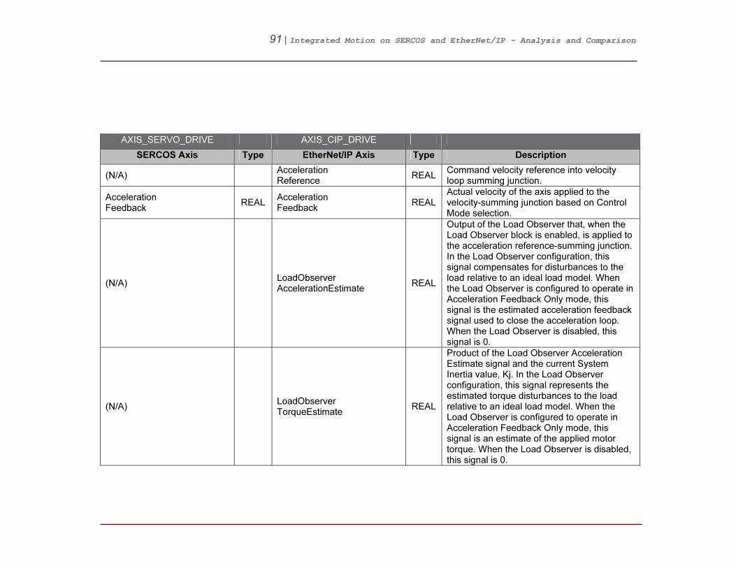
91 | Integrated Motion on SERCOS and EtherNet/IP - Analysis and Comparison
AXIS_SERVO_DRIVE AXIS_CIP_DRIVE
SERCOS Axis Type EtherNet/IP Axis Type Description
(N/A) Acceleration Reference
REAL Command velocity reference into velocity loop summing junction.
Acceleration Feedback
REAL Acceleration Feedback
REAL Actual velocity of the axis applied to the velocity-summing junction based on Control Mode selection.
(N/A) LoadObserver AccelerationEstimate
REAL
Output of the Load Observer that, when the Load Observer block is enabled, is applied to the acceleration reference-summing junction. In the Load Observer configuration, this signal compensates for disturbances to the load relative to an ideal load model. When the Load Observer is configured to operate in Acceleration Feedback Only mode, this signal is the estimated acceleration feedback signal used to close the acceleration loop. When the Load Observer is disabled, this signal is 0.
(N/A) LoadObserver TorqueEstimate
REAL
Product of the Load Observer Acceleration Estimate signal and the current System Inertia value, Kj. In the Load Observer configuration, this signal represents the estimated torque disturbances to the load relative to an ideal load model. When the Load Observer is configured to operate in Acceleration Feedback Only mode, this signal is an estimate of the applied motor torque. When the Load Observer is disabled, this signal is 0.
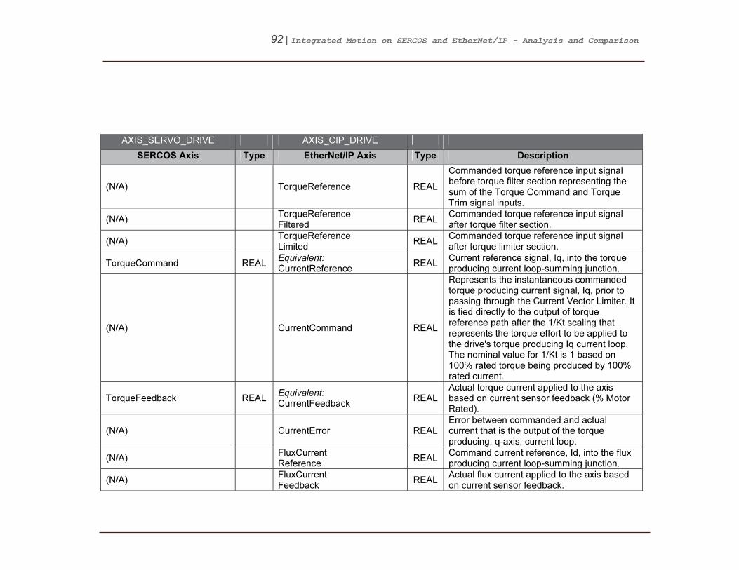
92 | Integrated Motion on SERCOS and EtherNet/IP - Analysis and Comparison
AXIS_SERVO_DRIVE AXIS_CIP_DRIVE
SERCOS Axis Type EtherNet/IP Axis Type Description
(N/A) TorqueReference REAL
Commanded torque reference input signal before torque filter section representing the sum of the Torque Command and Torque Trim signal inputs.
(N/A) TorqueReference Filtered
REAL Commanded torque reference input signal after torque filter section.
(N/A) TorqueReference Limited
REAL Commanded torque reference input signal after torque limiter section.
TorqueCommand REAL Equivalent: CurrentReference
REAL Current reference signal, Iq, into the torque producing current loop-summing junction.
(N/A) CurrentCommand REAL
Represents the instantaneous commanded torque producing current signal, Iq, prior to passing through the Current Vector Limiter. It is tied directly to the output of torque reference path after the 1/Kt scaling that represents the torque effort to be applied to the drive's torque producing Iq current loop. The nominal value for 1/Kt is 1 based on 100% rated torque being produced by 100% rated current.
TorqueFeedback REAL Equivalent: CurrentFeedback
REAL Actual torque current applied to the axis based on current sensor feedback (% Motor Rated).
(N/A) CurrentError REAL Error between commanded and actual current that is the output of the torque producing, q-axis, current loop.
(N/A) FluxCurrent Reference
REAL Command current reference, Id, into the flux producing current loop-summing junction.
(N/A) FluxCurrent Feedback
REAL Actual flux current applied to the axis based on current sensor feedback.

93 | Integrated Motion on SERCOS and EtherNet/IP - Analysis and Comparison
AXIS_SERVO_DRIVE AXIS_CIP_DRIVE
SERCOS Axis Type EtherNet/IP Axis Type Description
(N/A) FluxCurrentError REAL
Error between commanded and actual current that is the output of the flux producing, d-axis, current loop summing junction.
(N/A) OperativeCurrent Limit
REAL Represents the operative current limit based on multiple limit sources.
TorqueLimit Source
DINT Equivalent: CurrentLimit Source
DINT Represents the operative source of a current limit shall a current limit condition occur.
MotorElectrical Angle
REAL MotorElectrical Angle
REAL
The Motor Electrical Angle attribute is the calculated electrical angle of the motor based on motor pole count, commutation offset, and selected feedback device.
(N/A) SlipCompensation REAL Indicates the actual amount of slip compensation currently being applied.
(N/A) OutputFrequency REAL
The Output Frequency attribute is the time averaged output frequency applied to motor. Frequency value is in terms of electrical cycles.
(N/A) OutputCurrent REAL The Output Current attribute is the total time averaged output current applied to motor.
(N/A) OutputVoltage REAL The Output Voltage attribute is the total time averaged phase-to-phase output voltage applied to motor.
(N/A) OutputPower REAL
The Output Power attribute is the total time averaged output power of the motor. This value is based on the product of the Torque Reference signal and the Velocity Feedback.
DCBusVoltage REAL DCBusVoltage REAL Measured DC Bus Voltage.

94 | Integrated Motion on SERCOS and EtherNet/IP - Analysis and Comparison
AXIS_SERVO_DRIVE AXIS_CIP_DRIVE
SERCOS Axis Type EtherNet/IP Axis Type Description
MotorCapacity REAL MotorCapacity REAL
The Motor Capacity attribute is the real-time estimate of the continuous rated motor thermal capacity utilized during operation based on the motor thermal model. A value of 100% would indicate that the motor is being used at 100% of rated capacity as determined by the continuous current rating of the motor.
DriveCapacity REAL Equivalent: InverterCapacity
REAL
The Inverter Capacity attribute is the real-time estimate of the continuous rated inverter thermal capacity utilized during operation based on the inverter thermal model. A value of 100% would indicate that the inverter is being used at 100% of rated capacity as determined by the continuous current rating of the inverter.
PowerCapacity REAL Equivalent: Converter Capacity
REAL
The Converter Capacity attribute is the real-time estimate of the continuous rated converter thermal capacity utilized during operation based on the converter thermal model. A value of 100% would indicate that the converter is being used at 100% of rated capacity as determined by the continuous current rating of the converter.

95 | Integrated Motion on SERCOS and EtherNet/IP - Analysis and Comparison
AXIS_SERVO_DRIVE AXIS_CIP_DRIVE
SERCOS Axis Type EtherNet/IP Axis Type Description
BusRegulator Capacity
BusRegulator Capacity
REAL
The Bus Regulator Capacity attribute is the real-time estimate of the continuous rated bus regulator thermal capacity utilized during operation based on the bus regulator thermal model. A value of 100% would indicate that the bus regulator is being used at 100% of rated capacity as determined by the continuous current rating of the bus regulator.
(N/A) DigitalInputs DINT The Digital Inputs attribute is a 32-bit word with whose bits can be assigned by the vendor to general-purpose digital inputs.
AnalogInput1 REAL AnalogInput1 REAL The Analog Input 1 attribute is a general-purpose analog input 1 level.
AnalogInput2 REAL AnalogInput2 REAL The Analog Input 2 attribute is a general-purpose analog input 1 level.
(N/A) PositionTrim REAL
The Position Trim attribute is an additional position command added to the Position Command to generate the Position Reference signal into the position loop-summing junction.
VelocityOffset REAL Equivalent: VelocityTrim
REAL Additional velocity command added to the velocity loop-summing junction.
Acceleration Command
REAL Equivalent: AccelerationTrim
REAL Additional acceleration command added to the acceleration loop-summing junction.
TorqueOffset REAL Equivalent: TorqueTrim
REAL Additional torque command added to the torque input summing junction.
(N/A) VelocityFeed forwardGain
REAL
The Velocity Feedforward Gain attribute multiplies the Velocity Feedforward Command signal to form the Velocity Feedforward Command that is applied to the velocity loop-summing junction.

96 | Integrated Motion on SERCOS and EtherNet/IP - Analysis and Comparison
AXIS_SERVO_DRIVE AXIS_CIP_DRIVE
SERCOS Axis Type EtherNet/IP Axis Type Description
(N/A) Acceleration FeedforwardGain
REAL
The Acceleration Feedforward Gain attribute is a value that multiplies the Acceleration Fine Command signal to form the Acceleration Feedforward Command that is applied acceleration loop summing junction.
(N/A) PositionLoop Bandwidth
REAL
The Position Loop Bandwidth attribute determines the proportional gain, Kpp, of the position loop that multiplies the Position Error signal. This value represents the unity gain bandwidth of the position loop beyond which the position loop is ineffective.
(N/A) PositionIntegrator Bandwidth
REAL
The Position Integrator Bandwidth attribute determines the position loop integral gain, Kpi, which together with the Kpp, multiplies the integrated Position Error signal. This value represents the bandwidth of the position integrator beyond which the integrator is ineffective. A value of 0 for this attribute disables the integrator.
(N/A) VelocityLoop Bandwidth
REAL
The Velocity Loop Bandwidth attribute is a value that determines the proportional gain, Kvp, of the velocity loop that multiplies the Velocity Error signal. This value represents the unity gain bandwidth of the velocity loop.

97 | Integrated Motion on SERCOS and EtherNet/IP - Analysis and Comparison
AXIS_SERVO_DRIVE AXIS_CIP_DRIVE
SERCOS Axis Type EtherNet/IP Axis Type Description
(N/A) VelocityIntegrator Bandwidth
REAL
The Velocity Integrator Bandwidth attribute determines the velocity loop integral gain, Kvi, which together with the Kvp, multiplies the integrated Velocity Error signal. This value represents the bandwidth of the velocity integrator beyond which the integrator is ineffective. A value of 0 for this attribute disables the integrator.
(N/A) LoadObserver Bandwidth
REAL
The Load Observer Bandwidth attribute determines the proportional gain, Kop, of the load observer. This value represents the unity gain bandwidth of the load observer.
(N/A) LoadObserver IntegratorBandwidth
REAL
The Load Observer Integrator Bandwidth attribute determines the load observer integral gain, Koi, which together with the Kop, multiplies the integrated error signal within the observer. This value represents the bandwidth of the integrator beyond which the integrator is ineffective. A value of 0 for this attribute disables the integrator.
(N/A) TorqueLimit Positive
REAL
This positive value determines the maximum positive torque that can be applied to the motor. If the device attempts to exceed this value, the torque command is clamped to this value.
(N/A) TorqueLimit Negative
REAL
This negative value determines the most negative torque value that can be applied to the motor. If the device attempts to apply a more negative torque than this limit, the torque command is clamped to this value.

98 | Integrated Motion on SERCOS and EtherNet/IP - Analysis and Comparison
AXIS_SERVO_DRIVE AXIS_CIP_DRIVE
SERCOS Axis Type EtherNet/IP Axis Type Description
(N/A) VelocityLowPass FilterBandwidth
REAL
The Velocity Low Pass Filter Bandwidth attribute controls the bandwidth of the Low Pass Filter applied to the Velocity Error signal. Recommended implementation is a two-pole IIR filter. A value of 0 for this attribute disabled this feature.
(N/A) TorqueLowPass FilterBandwidth
REAL Break frequency for the 2nd order low pass filter applied to torque reference signal.
(N/A) SystemInertia REAL
Torque or force scaling gain value that converts commanded acceleration into equivalent rated torque/force. Properly set, this value represents the total system inertia or mass.
(N/A) Current Disturbance
REAL Injected torque producing current command used to excite motor as part of Frequency Analysis service.
(N/A) DigitalOutputs DINT The Digital Outputs attribute is a 32-bit word whose bits can be assigned by the vendor to general-purpose digital outputs.
(N/A) AnalogOutput1 REAL The Analog Output 1 attribute is a general-purpose analog output 1 level.
(N/A) AnalogOutput2 REAL The Analog Output 1 attribute is a general-purpose analog output 2 level.
MarkerDistance REAL (N/A) Marker Distance in Position Units.
PosDynamicTorqueLimit REAL (N/A)
The currently operative maximum positive torque/current limits magnitude. It should be the lowest value of all torque/current limits in the drive at a given time, including: amplifier peak limit, motor peak limit, user current limit, amplifier thermal limit, and motor thermal limit.

99 | Integrated Motion on SERCOS and EtherNet/IP - Analysis and Comparison
AXIS_SERVO_DRIVE AXIS_CIP_DRIVE
SERCOS Axis Type EtherNet/IP Axis Type Description
NegDynamic TorqueLimit
REAL (N/A)
The currently operative negative positive torque/current limits magnitude. It should be the lowest value of all torque/current limits in the drive at a given time, including: amplifier peak limit, motor peak limit, user current limit, amplifier thermal limit, and motor thermal limit.

100 | Integrated Motion on SERCOS and EtherNet/IP - Analysis and Comparison
AXIS_SERVO_DRIVE AXIS_CIP_DRIVE
SERCOS Axis Type EtherNet/IP Axis Type Description
DriveStatus DINT (N/A)
The status bits for your servo drive: Bit: Number: Data Type: Description: - no tag - 00 DINT Servo Action Status - no tag - 01 DINT Drive Enable Status - no tag - 02 DINT Axis Shutdown Status ProcessStatus 03 DINT Process Status Reserved 04-05, HomeInputStatus 06 DINT Home Input Status Reg1InputStatus 07 DINT Registration 1 Input Status Reg2InputStatus 08 DINT Registration 12Input Status PosOvertravelInputStatus 09 DINT Positive Overtravel Input Status NegOvertravelInputStatus 10 DINT Negative Overtravel Input Status EnableInputStatus 11 DINT Enable Input Status AccelLimitStatus 12 DINT Accel Limit Status AbsoluteReferenceStatus 13 DINT Absolute Reference Status Reserved 14-15 VelocityLockStatus 16 DINT Velocity Lock Status VelocityStandstillStatus 17 DINT Velocity Standstill Status VelocityThresholdStatus 18 DINT Velocity Threshold Status TorqueThresholdStatus 19 DINT Torque Threshold Status TorqueLimitStatus 20 DINT Torque Limit Status VelocityLimitStatus 21 DINT Velocity Limit Status PosLockStatus 22 DINT Position Lock Status Reserved 23-31 (Reserved)
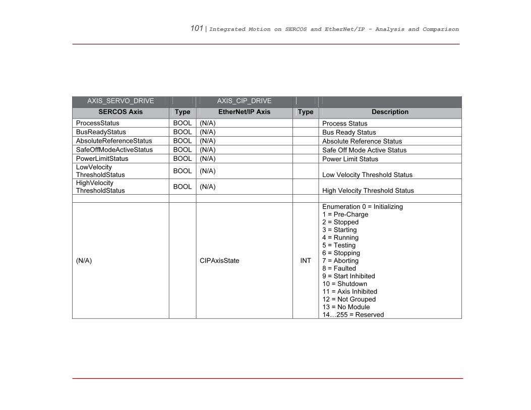
101 | Integrated Motion on SERCOS and EtherNet/IP - Analysis and Comparison
AXIS_SERVO_DRIVE AXIS_CIP_DRIVE
SERCOS Axis Type EtherNet/IP Axis Type Description
ProcessStatus BOOL (N/A) Process Status
BusReadyStatus BOOL (N/A) Bus Ready Status
AbsoluteReferenceStatus BOOL (N/A) Absolute Reference Status
SafeOffModeActiveStatus BOOL (N/A) Safe Off Mode Active Status
PowerLimitStatus BOOL (N/A) Power Limit Status
LowVelocity ThresholdStatus
BOOL (N/A) Low Velocity Threshold Status
HighVelocity ThresholdStatus
BOOL (N/A) High Velocity Threshold Status
(N/A) CIPAxisState INT
Enumeration 0 = Initializing 1 = Pre-Charge 2 = Stopped 3 = Starting 4 = Running 5 = Testing 6 = Stopping 7 = Aborting 8 = Faulted 9 = Start Inhibited 10 = Shutdown 11 = Axis Inhibited 12 = Not Grouped 13 = No Module 14…255 = Reserved

102 | Integrated Motion on SERCOS and EtherNet/IP - Analysis and Comparison
AXIS_SERVO_DRIVE AXIS_CIP_DRIVE
SERCOS Axis Type EtherNet/IP Axis Type Description
(N/A) CIPAxisStatus DINT
Bitmap 0 = Local Control 1 = Alarm 2 = DC Bus Up 3 = Power Structure Enabled 4 = Motor Flux Up 5 = Tracking Command 6 = Position Lock 7 = Velocity Lock 8 = Velocity Standstill 9 = Velocity Threshold 10 = Velocity Limit 11 = Acceleration Limit 12 = Deceleration Limit 13 = Torque Threshold 14 = Torque Limit 15 = Current Limit 16 = Thermal Limit 17 = Feedback Integrity 18 = Shutdown 19 = In Process 20…31 = Reserved
(N/A) LocalControl Status
BOOL This bit is set if axis is taking command reference and services from local interface instead of the remote (CIP Motion) interface.
(N/A) AlarmStatus BOOL This bit is set if the axis has detected one or more exception conditions configured to generate an alarm.
(N/A) DCBusUpStatus BOOL This bit is set if DC Bus has charged up to an operational voltage level.

103 | Integrated Motion on SERCOS and EtherNet/IP - Analysis and Comparison
AXIS_SERVO_DRIVE AXIS_CIP_DRIVE
SERCOS Axis Type EtherNet/IP Axis Type Description
(N/A) PowerStructure EnabledStatus
BOOL This bit is set if the axis amplifier is energized and capable of generating motor flux and torque.
(N/A) MotorFluxUp Status
BOOL This bit is set if motor flux for an induction motor has reached an operational level.
(N/A) Tracking CommandStatus
BOOL This bit is set if the axis control structure is now actively tracking the command reference from motion planner.
PositionLock Status
BOOL PositionLock Status
BOOL This bit is set if the actual position is within Position Lock Tolerance of command position.
VelocityLock Status
BOOL VelocityLock Status
BOOL This bit is set if the velocity feedback signal is within Velocity Lock Tolerance of the unlimited velocity reference.
VelocityStandstill Status
BOOL VelocityStandstill Status
BOOL This bit is set if the velocity feedback signal is within Velocity Standstill Window of 0.
VelocityThreshold Status
BOOL VelocityThreshold Status
BOOL This bit is set if the absolute velocity feedback signal is below Velocity Threshold.
VelocityLimit Status
BOOL VelocityLimit Status
BOOL This bit is set if the velocity reference signal is currently being limited by the Velocity Limiter.
AccelLimitStatus BOOL AccelerationLimit Status
BOOL This bit is set if the acceleration reference signal is currently being limited by the Acceleration Limiter.
(N/A) DecelerationLimit Status
BOOL This bit is set if the acceleration reference signal is currently being limited by the Deceleration Limiter.
TorqueThreshold Status
BOOL TorqueThreshold Status
BOOL This bit is set if the absolute filtered torque reference is above the Torque Threshold.
TorqueLimitStatus BOOL TorqueLimit Status
BOOL This bit is set if the filtered torque reference is currently being limited by the Torque Limiter.

104 | Integrated Motion on SERCOS and EtherNet/IP - Analysis and Comparison
AXIS_SERVO_DRIVE AXIS_CIP_DRIVE
SERCOS Axis Type EtherNet/IP Axis Type Description
(N/A) CurrentLimit Status
BOOL This bit is set if the command current, Iq, is currently being limited by the Current Vector Limiter.
(N/A) ThermalLimit Status
BOOL This bit is set if Current Vector Limit condition of the axis is being limited by any of the axis’s Thermal Models.
(N/A) FeedbackIntegrity Status
BOOL
This bit, when set, indicates that the feedback device is accurately reflecting changes to axis position, and there have been no conditions detected that would compromise the quality of the feedback position value. The bit is set at power up assuming that the feedback device passes any power-up self test required. If Feedback Integrity is cleared, the Axis Homed Status attribute is also cleared. This prevents Soft Overtravel checking If during operation a feedback exception occurs that could impact the fidelity of axis position, the bit is immediately cleared. The bit remains clear until either a fault reset is executed by the drive or the drive is power cycled. Fault Resets can be generated directly by the drive or initiated by the controller via motion instructions. NOTE that the Feedback Integrity bit behavior applies to both absolute and incremental feedback device operation.

105 | Integrated Motion on SERCOS and EtherNet/IP - Analysis and Comparison
AXIS_SERVO_DRIVE AXIS_CIP_DRIVE
SERCOS Axis Type EtherNet/IP Axis Type Description
(N/A) CIPShutdown Status
BOOL
This bit is set when the axis is in the shutdown state or in the faulted state but would transition to the shutdown state if the faults were cleared.
(N/A) InProcessStatus BOOL
This bit is set for the duration of an active process. An example of active process would be an operation initiated by a Run Motor Test, Run Hookup Test, or Run Inertia Test request service.
(N/A) CIPAxisStatusRA DINT 0…31 = Reserved
(N/A) CIPAxisIOStatus DINT Bitmap 0 = Regenerative Power Input Status 1…31 = Reserved
EnableInputStatus BOOL EnableInputStatus BOOL Enable Input Status
HomeInputStatus BOOL HomeInputStatus BOOL Home Input Status
Reg1InputStatus BOOL Registration1Input Status
BOOL Registration 1 Input Status
Reg2InputStatus BOOL Registration2Input Status
BOOL Registration 2 Input Status
PosOvertravel InputStatus
BOOL PositiveOvertravel InputStatus
BOOL Positive Overtravel Input Status
NegOvertravel InputStatus
BOOL Negative OvertravelInputStatus
BOOL Negative Overtravel Input Status
(N/A) Feedback1 ThermostatStatus
BOOL Feedback 1 Thermostat Status
(N/A) ResistiveBrake OutputStatus
BOOL Resistive Brake Output Status
(N/A) MechanicalBrake OutputStatus
BOOL Mechanical Brake Output Status
(N/A) CIPAxisIOStatus RA
DINT 0 … 31 = Reserved

106 | Integrated Motion on SERCOS and EtherNet/IP - Analysis and Comparison
AXIS_SERVO_DRIVE AXIS_CIP_DRIVE
SERCOS Axis Type EtherNet/IP Axis Type Description
(N/A) Regenerative PowerInputStatus
BOOL This bit represents the logical state of the Regenerative Power Input
(N/A) CIPStartInhibits INT
Bitwise 1 = Axis Enable Input 2 = Motor Not Configured 3 = Feedback Not Configured 4 … 15 = Reserved
(N/A) AxisEnableInput Inhibit
BOOL Axis Enable Input is not active.
(N/A) MotorNot ConfiguredInhibit
BOOL The associated motor has not been configured for use.
(N/A) FeedbackNot ConfiguredInhibit
BOOL The associated feedback device has not been configured.
(N/A) CIPStartInhibits RA
INT
Bitwise 1 = Volts Hertz Curve Definition Inhibit 2 = Motor Feedback Required Inhibit 3 = Speed Limit Configuration Inhibit 4 = Torque Prove Configuration Inhibit 5 = Safe Torque Off Inhibit 6 = Safety Reset Required Inhibit 8 … 15 = Reserved
(N/A) VoltsHertzCurve DefinitionInhibit
BOOL Conflict exists in the V/Hz curve definition.
(N/A) MotorFeedback RequiredInhibit
BOOL Can't run using the selected motor control mode with Primary Feedback or Alternate Feedback set as open loop.
(N/A) SpeedLimit ConfigurationInhibit
BOOL
Speed Ref Limit Conflict, either Minimum Forward Speed Limit exceeds Maximum Forward Speed Limit, or Minimum Reverse Speed Limit exceeds Maximum Reverse Speed Limit.

107 | Integrated Motion on SERCOS and EtherNet/IP - Analysis and Comparison
AXIS_SERVO_DRIVE AXIS_CIP_DRIVE
SERCOS Axis Type EtherNet/IP Axis Type Description
(N/A) TorqueProve ConfigurationInhibit
BOOL
When Torque Prove Config is enabled, Control Mode, Feedback Mode, Motor Feedback Type, and Motor Option Configuration shall be properly set.
(N/A) SafeTorqueOff Inhibit
BOOL The safety function has disabled the power structure.
(N/A) SafetyReset RequiredInhibit
BOOL The safety reset input needs to be toggled before the safety board will allow motion again.
(N/A) SafetyNot ConfiguredInhibit
BOOL The embedded safety function of the drive has not been configured.
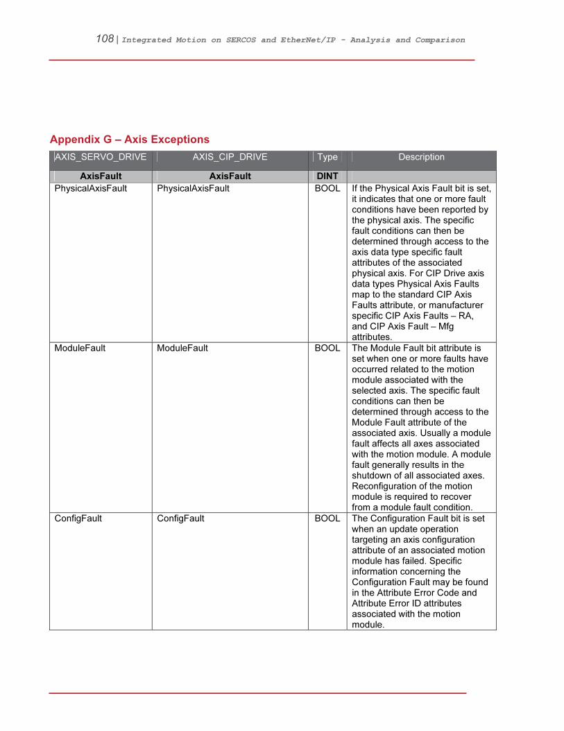
108 | Integrated Motion on SERCOS and EtherNet/IP - Analysis and Comparison
19BAppendix G – Axis Exceptions
AXIS_SERVO_DRIVE AXIS_CIP_DRIVE Type Description
AxisFault AxisFault DINT
PhysicalAxisFault PhysicalAxisFault BOOL If the Physical Axis Fault bit is set, it indicates that one or more fault conditions have been reported by the physical axis. The specific fault conditions can then be determined through access to the axis data type specific fault attributes of the associated physical axis. For CIP Drive axis data types Physical Axis Faults map to the standard CIP Axis Faults attribute, or manufacturer specific CIP Axis Faults – RA, and CIP Axis Fault – Mfg attributes.
ModuleFault ModuleFault BOOL The Module Fault bit attribute is set when one or more faults have occurred related to the motion module associated with the selected axis. The specific fault conditions can then be determined through access to the Module Fault attribute of the associated axis. Usually a module fault affects all axes associated with the motion module. A module fault generally results in the shutdown of all associated axes. Reconfiguration of the motion module is required to recover from a module fault condition.
ConfigFault ConfigFault BOOL The Configuration Fault bit is set when an update operation targeting an axis configuration attribute of an associated motion module has failed. Specific information concerning the Configuration Fault may be found in the Attribute Error Code and Attribute Error ID attributes associated with the motion module.

109 | Integrated Motion on SERCOS and EtherNet/IP - Analysis and Comparison
AXIS_SERVO_DRIVE AXIS_CIP_DRIVE Type Description
GroupFault GroupFault BOOL The Group Fault bit attribute is set when one or more faults have occurred related to the motion group associated with the selected axis. The specific fault conditions can then be determined through access to the Group Fault attribute of the associated motion group. Usually a group fault affects all axes associated with the motion group. A group fault generally results in the shutdown of all associated axes. Reconfiguration of the entire motion subsystem is required to recover from a group fault condition.
(N/A) MotionFault BOOL If the Motion Fault bit is set, it indicates that there is one or more fault conditions have occurred related to the Motion Planner function. The specific fault conditions can then be determined through access to the Motion Fault attribute of the associated axis.
Equivalent: GuardFaultExists
GuardFault BOOL If the Guard Fault bit is set, it indicates that there is one or more fault conditions that have occurred related to the Guard Motion safety function. The specific fault conditions can then be determined through access to the Guard Motion attribute of the associated axis. Guard Faults are only applicable if the drive device is equipped with Guard Safety functionality.

110 | Integrated Motion on SERCOS and EtherNet/IP - Analysis and Comparison
AXIS_SERVO_DRIVE AXIS_CIP_DRIVE Type Description
(N/A) InitializationFault BOOL The Initialization Fault bit is set when initialization of a CIP Motion drive fails for any reason. Specific information concerning the Initialization Fault may be found in the standard CIP Initialization attribute, or manufacturer specific CIP Initialization Fault – RA, and CIP Initialization Fault – Mfg attributes associated with the CIP Drive axis data types.
(N/A) APRFault BOOL The APR (Absolute Position Recovery) Fault bit is set when during axis configuration the system is not able to recover the absolute position of the axis. Specific information concerning the APR Fault may be found in the standard APR Fault attribute, or manufacturer specific APR Fault – RA, and APR Fault – Mfg attributes associated with the CIP Drive axis data types.
(N/A) MotionAlarmStatus DINT These two attributes collect the fault and alarm exception conditions associated with the Motion Planner. When one of the listed excepted conditions is detected by the controller, the condition is indicated as a Fault or Alarm according to the associated Motion Exception Action attribute value. In general, Alarms are considered warnings by the control system while Faults result in some form of action to stop the axis.
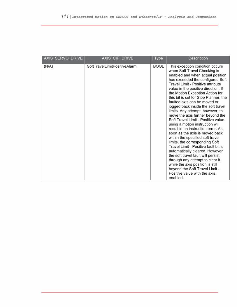
111 | Integrated Motion on SERCOS and EtherNet/IP - Analysis and Comparison
AXIS_SERVO_DRIVE AXIS_CIP_DRIVE Type Description
(N/A) SoftTravelLimitPositiveAlarm BOOL This exception condition occurs when Soft Travel Checking is enabled and when actual position has exceeded the configured Soft Travel Limit - Positive attribute value in the positive direction. If the Motion Exception Action for this bit is set for Stop Planner, the faulted axis can be moved or jogged back inside the soft travel limits. Any attempt, however, to move the axis further beyond the Soft Travel Limit - Positive value using a motion instruction will result in an instruction error. As soon as the axis is moved back within the specified soft travel limits, the corresponding Soft Travel Limit - Positive fault bit is automatically cleared. However the soft travel fault will persist through any attempt to clear it while the axis position is still beyond the Soft Travel Limit - Positive value with the axis enabled.

112 | Integrated Motion on SERCOS and EtherNet/IP - Analysis and Comparison
AXIS_SERVO_DRIVE AXIS_CIP_DRIVE Type Description
(N/A) SoftTravelLimitNegativeAlarm BOOL This exception condition occurs when Soft Travel Checking is enabled and when actual position has exceeded the configured Soft Travel Limit - Negative attribute value in the negative direction. If the Motion Exception Action for this bit is set for Stop Planner, the faulted axis can be moved or jogged back inside the soft travel limits. Any attempt, however, to move the axis further beyond the Soft Travel Limit - Negative value using a motion instruction will result in an instruction error. As soon as the axis is moved back within the specified soft travel limits, the corresponding Soft Travel Limit - Negative fault bit is automatically cleared. However the soft travel fault will persist through any attempt to clear it while the axis position is still beyond the Soft Travel Limit - Negative value with the axis enabled.
(N/A) MotionFaultStatus DINT These two attributes collect the fault and alarm exception conditions associated with the Motion Planner. When one of the listed excepted conditions is detected by the controller, the condition is indicated as a Fault or Alarm according to the associated Motion Exception Action attribute value. In general, Alarms are considered warnings by the control system while Faults result in some form of action to stop the axis.

113 | Integrated Motion on SERCOS and EtherNet/IP - Analysis and Comparison
AXIS_SERVO_DRIVE AXIS_CIP_DRIVE Type Description
Equivalent: PosSoftOvertravel Fault
SoftTravelLimitPositiveFault BOOL This exception condition occurs when Soft Travel Checking is enabled and when actual position has exceeded the configured Soft Travel Limit - Positive attribute value in the positive direction. If the Motion Exception Action for this bit is set for Stop Planner, the faulted axis can be moved or jogged back inside the soft travel limits. Any attempt, however, to move the axis further beyond the Soft Travel Limit - Positive value using a motion instruction will result in an instruction error. As soon as the axis is moved back within the specified soft travel limits, the corresponding Soft Travel Limit - Positive fault bit is automatically cleared. However the soft travel fault will persist through any attempt to clear it while the axis position is still beyond the Soft Travel Limit - Positive value with the axis enabled.
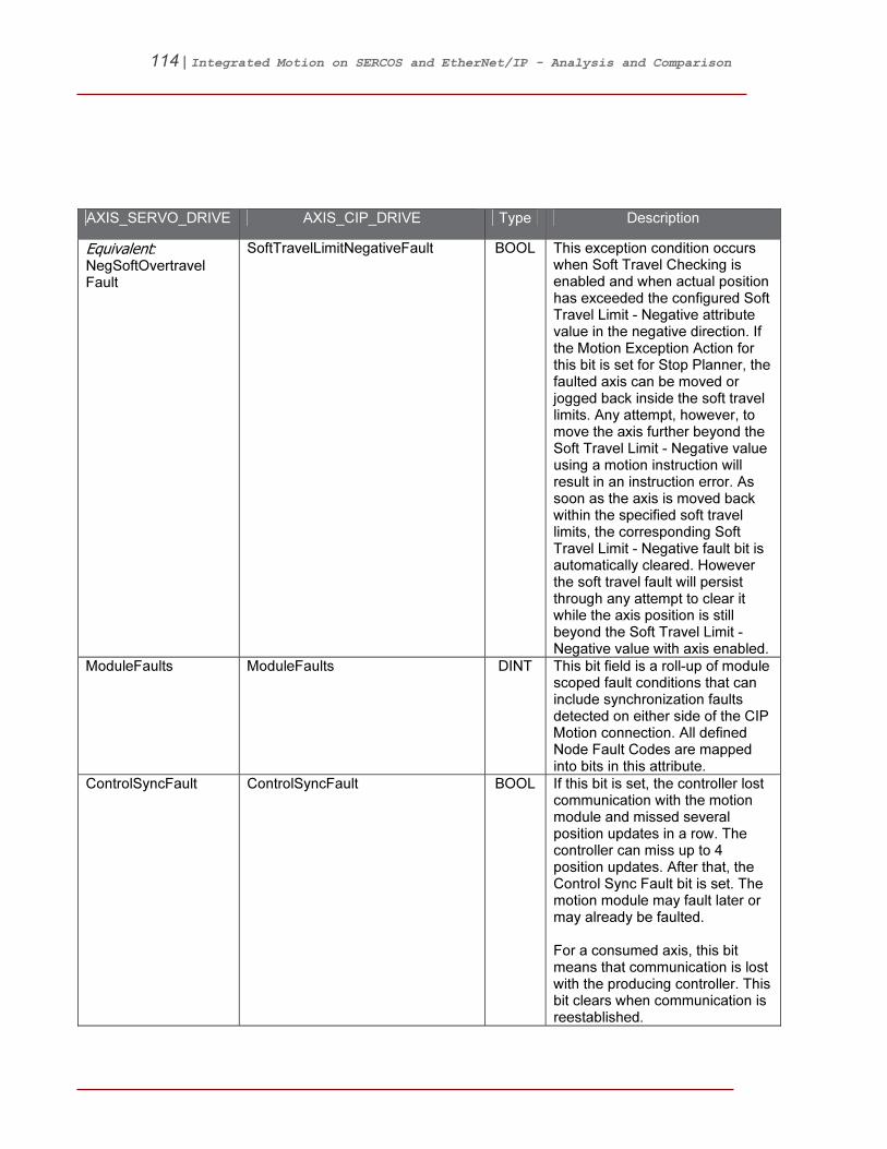
114 | Integrated Motion on SERCOS and EtherNet/IP - Analysis and Comparison
AXIS_SERVO_DRIVE AXIS_CIP_DRIVE Type Description
Equivalent: NegSoftOvertravel Fault
SoftTravelLimitNegativeFault BOOL This exception condition occurs when Soft Travel Checking is enabled and when actual position has exceeded the configured Soft Travel Limit - Negative attribute value in the negative direction. If the Motion Exception Action for this bit is set for Stop Planner, the faulted axis can be moved or jogged back inside the soft travel limits. Any attempt, however, to move the axis further beyond the Soft Travel Limit - Negative value using a motion instruction will result in an instruction error. As soon as the axis is moved back within the specified soft travel limits, the corresponding Soft Travel Limit - Negative fault bit is automatically cleared. However the soft travel fault will persist through any attempt to clear it while the axis position is still beyond the Soft Travel Limit - Negative value with axis enabled.
ModuleFaults ModuleFaults DINT This bit field is a roll-up of module scoped fault conditions that can include synchronization faults detected on either side of the CIP Motion connection. All defined Node Fault Codes are mapped into bits in this attribute.
ControlSyncFault ControlSyncFault BOOL If this bit is set, the controller lost communication with the motion module and missed several position updates in a row. The controller can miss up to 4 position updates. After that, the Control Sync Fault bit is set. The motion module may fault later or may already be faulted. For a consumed axis, this bit means that communication is lost with the producing controller. This bit clears when communication is reestablished.
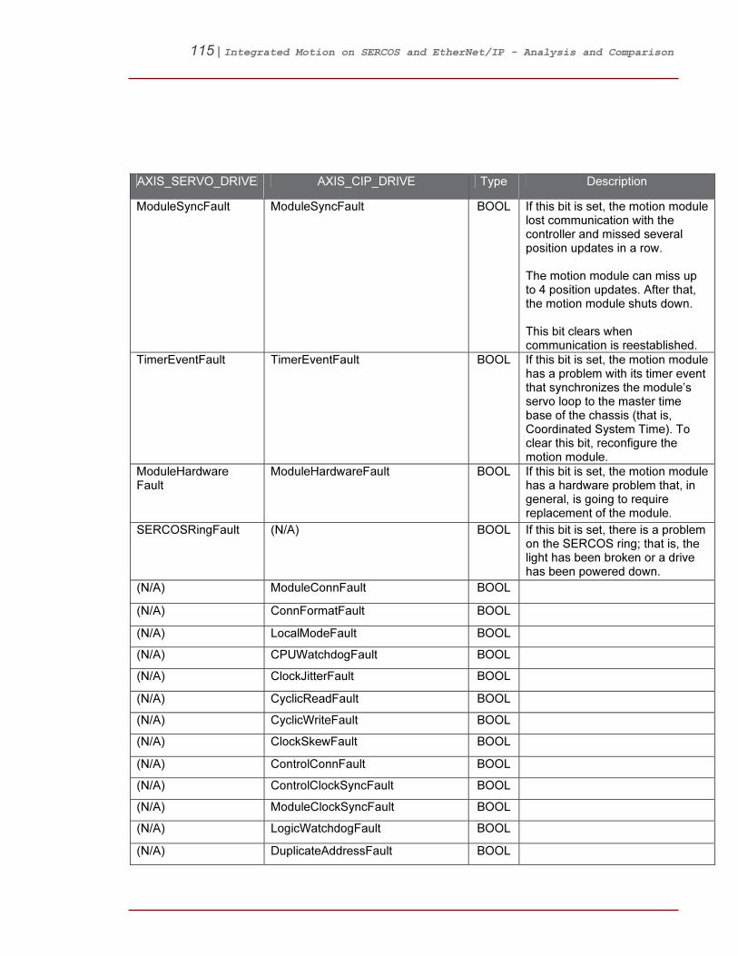
115 | Integrated Motion on SERCOS and EtherNet/IP - Analysis and Comparison
AXIS_SERVO_DRIVE AXIS_CIP_DRIVE Type Description
ModuleSyncFault ModuleSyncFault BOOL If this bit is set, the motion module lost communication with the controller and missed several position updates in a row. The motion module can miss up to 4 position updates. After that, the motion module shuts down. This bit clears when communication is reestablished.
TimerEventFault TimerEventFault BOOL If this bit is set, the motion module has a problem with its timer event that synchronizes the module’s servo loop to the master time base of the chassis (that is, Coordinated System Time). To clear this bit, reconfigure the motion module.
ModuleHardware Fault
ModuleHardwareFault BOOL If this bit is set, the motion module has a hardware problem that, in general, is going to require replacement of the module.
SERCOSRingFault (N/A) BOOL If this bit is set, there is a problem on the SERCOS ring; that is, the light has been broken or a drive has been powered down.
(N/A) ModuleConnFault BOOL
(N/A) ConnFormatFault BOOL
(N/A) LocalModeFault BOOL
(N/A) CPUWatchdogFault BOOL
(N/A) ClockJitterFault BOOL
(N/A) CyclicReadFault BOOL
(N/A) CyclicWriteFault BOOL
(N/A) ClockSkewFault BOOL
(N/A) ControlConnFault BOOL
(N/A) ControlClockSyncFault BOOL
(N/A) ModuleClockSyncFault BOOL
(N/A) LogicWatchdogFault BOOL
(N/A) DuplicateAddressFault BOOL
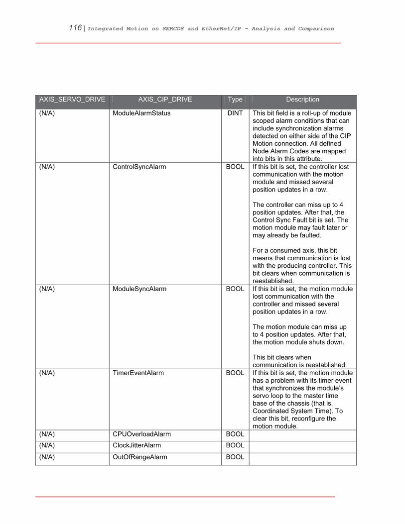
116 | Integrated Motion on SERCOS and EtherNet/IP - Analysis and Comparison
AXIS_SERVO_DRIVE AXIS_CIP_DRIVE Type Description
(N/A) ModuleAlarmStatus DINT This bit field is a roll-up of module scoped alarm conditions that can include synchronization alarms detected on either side of the CIP Motion connection. All defined Node Alarm Codes are mapped into bits in this attribute.
(N/A) ControlSyncAlarm BOOL If this bit is set, the controller lost communication with the motion module and missed several position updates in a row. The controller can miss up to 4 position updates. After that, the Control Sync Fault bit is set. The motion module may fault later or may already be faulted. For a consumed axis, this bit means that communication is lost with the producing controller. This bit clears when communication is reestablished.
(N/A) ModuleSyncAlarm BOOL If this bit is set, the motion module lost communication with the controller and missed several position updates in a row. The motion module can miss up to 4 position updates. After that, the motion module shuts down. This bit clears when communication is reestablished.
(N/A) TimerEventAlarm BOOL If this bit is set, the motion module has a problem with its timer event that synchronizes the module’s servo loop to the master time base of the chassis (that is, Coordinated System Time). To clear this bit, reconfigure the motion module.
(N/A) CPUOverloadAlarm BOOL
(N/A) ClockJitterAlarm BOOL
(N/A) OutOfRangeAlarm BOOL

117 | Integrated Motion on SERCOS and EtherNet/IP - Analysis and Comparison
AXIS_SERVO_DRIVE AXIS_CIP_DRIVE Type Description
(N/A) ClockSkewAlarm BOOL
AxisFault AxisFault
PosHardOvertravel Fault
Equivalent: HardwareOvertravelPositive Fault
BOOL Set if the axis moves beyond the current position limits as established by hardware overtravel limit switches mounted on the equipment. This fault can only occur when the drive is in the enabled state and the Hard Overtravel Checking bit is set in the Fault Configuration Bits attribute. If the Hard Overtravel Fault Action is set for Stop Command, the faulted axis can be moved or jogged back inside the soft overtravel limits. Any attempt, however, to move the axis further beyond the hard overtravel limit switch using a motion instruction results in an instruction error. To recover from this fault, the axis must be moved back within normal operation limits of the equipment and the limit switch closed. This fault condition is latched and requires execution of a Motion Axis Fault Reset (MAFR) or Motion Axis Shutdown Reset (MASR) instruction to clear. Any attempt to clear the fault while the overtravel limit switch is still open and the drive is enabled is unsuccessful.
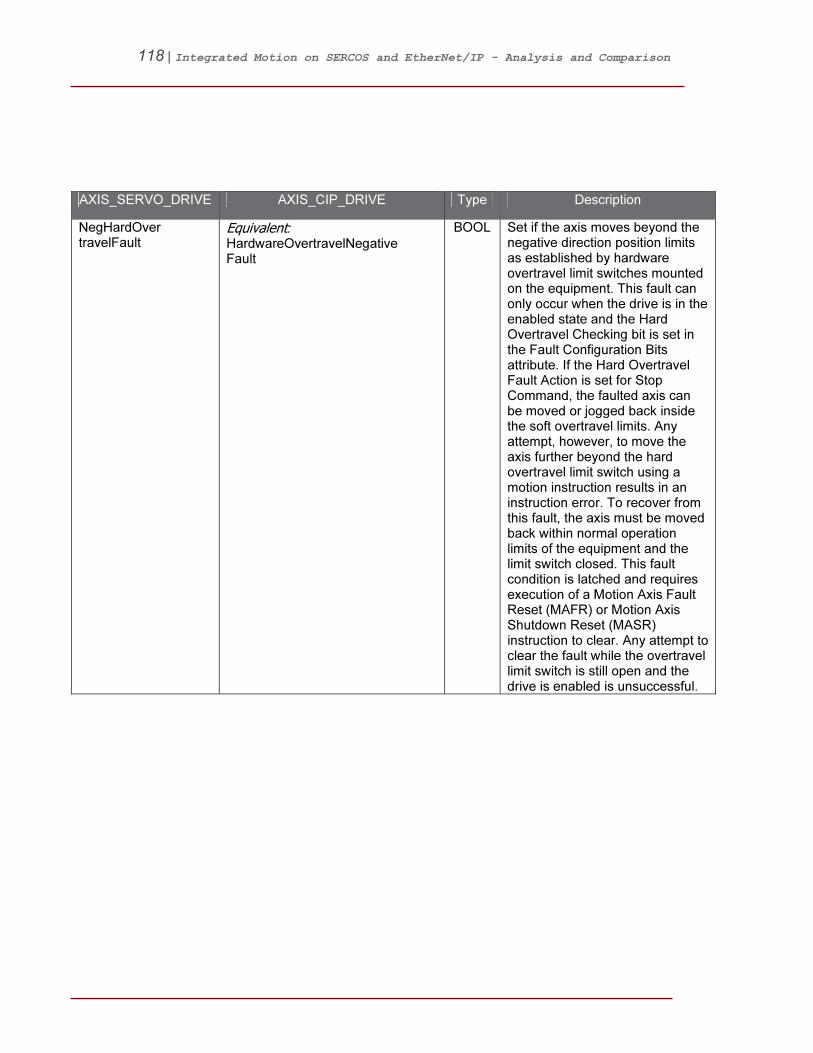
118 | Integrated Motion on SERCOS and EtherNet/IP - Analysis and Comparison
AXIS_SERVO_DRIVE AXIS_CIP_DRIVE Type Description
NegHardOver travelFault
Equivalent: HardwareOvertravelNegative Fault
BOOL Set if the axis moves beyond the negative direction position limits as established by hardware overtravel limit switches mounted on the equipment. This fault can only occur when the drive is in the enabled state and the Hard Overtravel Checking bit is set in the Fault Configuration Bits attribute. If the Hard Overtravel Fault Action is set for Stop Command, the faulted axis can be moved or jogged back inside the soft overtravel limits. Any attempt, however, to move the axis further beyond the hard overtravel limit switch using a motion instruction results in an instruction error. To recover from this fault, the axis must be moved back within normal operation limits of the equipment and the limit switch closed. This fault condition is latched and requires execution of a Motion Axis Fault Reset (MAFR) or Motion Axis Shutdown Reset (MASR) instruction to clear. Any attempt to clear the fault while the overtravel limit switch is still open and the drive is enabled is unsuccessful.
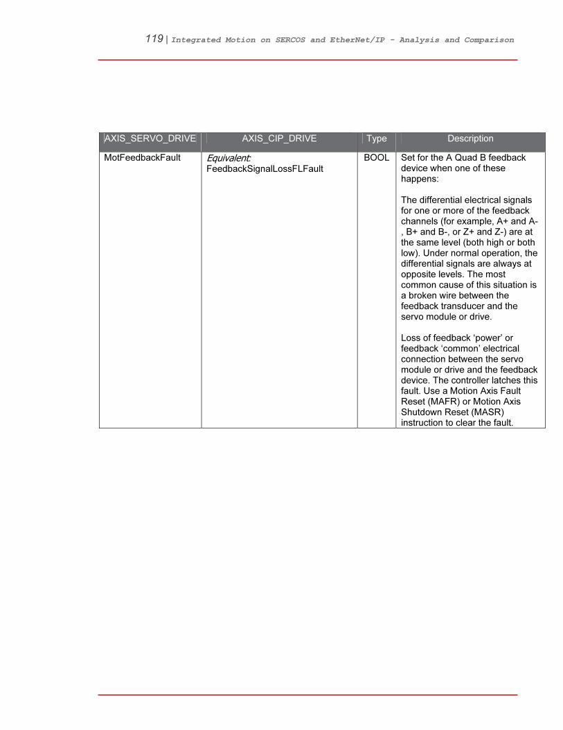
119 | Integrated Motion on SERCOS and EtherNet/IP - Analysis and Comparison
AXIS_SERVO_DRIVE AXIS_CIP_DRIVE Type Description
MotFeedbackFault Equivalent: FeedbackSignalLossFLFault
BOOL Set for the A Quad B feedback device when one of these happens: The differential electrical signals for one or more of the feedback channels (for example, A+ and A-, B+ and B-, or Z+ and Z-) are at the same level (both high or both low). Under normal operation, the differential signals are always at opposite levels. The most common cause of this situation is a broken wire between the feedback transducer and the servo module or drive. Loss of feedback ‘power’ or feedback ‘common’ electrical connection between the servo module or drive and the feedback device. The controller latches this fault. Use a Motion Axis Fault Reset (MAFR) or Motion Axis Shutdown Reset (MASR) instruction to clear the fault.
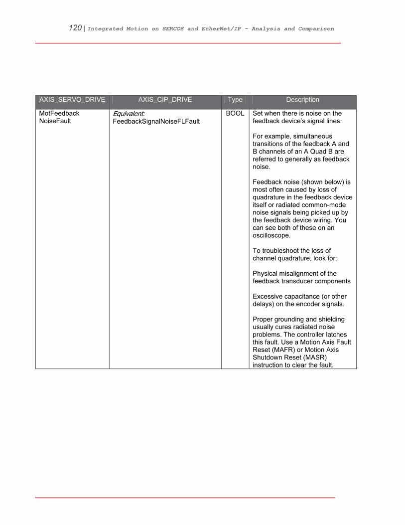
120 | Integrated Motion on SERCOS and EtherNet/IP - Analysis and Comparison
AXIS_SERVO_DRIVE AXIS_CIP_DRIVE Type Description
MotFeedback NoiseFault
Equivalent: FeedbackSignalNoiseFLFault
BOOL Set when there is noise on the feedback device’s signal lines. For example, simultaneous transitions of the feedback A and B channels of an A Quad B are referred to generally as feedback noise. Feedback noise (shown below) is most often caused by loss of quadrature in the feedback device itself or radiated common-mode noise signals being picked up by the feedback device wiring. You can see both of these on an oscilloscope. To troubleshoot the loss of channel quadrature, look for: Physical misalignment of the feedback transducer components Excessive capacitance (or other delays) on the encoder signals. Proper grounding and shielding usually cures radiated noise problems. The controller latches this fault. Use a Motion Axis Fault Reset (MAFR) or Motion Axis Shutdown Reset (MASR) instruction to clear the fault.
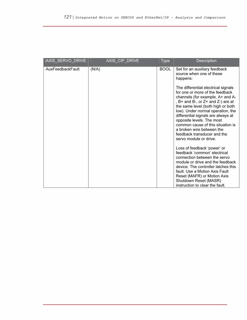
121 | Integrated Motion on SERCOS and EtherNet/IP - Analysis and Comparison
AXIS_SERVO_DRIVE AXIS_CIP_DRIVE Type Description
AuxFeedbackFault (N/A) BOOL Set for an auxiliary feedback source when one of these happens: The differential electrical signals for one or more of the feedback channels (for example, A+ and A-, B+ and B-, or Z+ and Z-) are at the same level (both high or both low). Under normal operation, the differential signals are always at opposite levels. The most common cause of this situation is a broken wire between the feedback transducer and the servo module or drive. Loss of feedback ‘power’ or feedback ‘common’ electrical connection between the servo module or drive and the feedback device. The controller latches this fault. Use a Motion Axis Fault Reset (MAFR) or Motion Axis Shutdown Reset (MASR) instruction to clear the fault.

122 | Integrated Motion on SERCOS and EtherNet/IP - Analysis and Comparison
AXIS_SERVO_DRIVE AXIS_CIP_DRIVE Type Description
AuxFeedbackNoise Fault
(N/A) BOOL Set when there is noise on the feedback device’s signal lines. For example, simultaneous transitions of the feedback A and B channels of an A Quad B are referred to generally as feedback noise. Feedback noise (shown below) is most often caused by loss of quadrature in the feedback device itself or radiated common-mode noise signals being picked up by the feedback device wiring. You can see both of these on an oscilloscope. To troubleshoot the loss of channel quadrature, look for: > physical misalignment of the feedback transducer components > excessive capacitance (or other delays) on the encoder signals Proper grounding and shielding usually cures radiated noise problems. The controller latches this fault. Use a Motion Axis Fault Reset (MAFR) or Motion Axis Shutdown Reset (MASR) instruction to clear the fault.
DriveEnableInput Fault
Equivalent: EnableInputDeactivatedFault
BOOL This fault would be declared if either one of two possible conditions occur: 1) If an attempt is made to enable the axis (typically via MSO or MAH instruction) while the Drive Enable Input is inactive. 2) If the Drive Enable Input transitions from active to inactive while the axis is enabled. This fault can only occur when the Drive Enable Input Fault Handling bit is set in the Fault Configuration Bits attribute. If the Drive Enable

123 | Integrated Motion on SERCOS and EtherNet/IP - Analysis and Comparison
AXIS_SERVO_DRIVE AXIS_CIP_DRIVE Type Description
Input Fault Action is set for Stop Command and the axis is stopped because of a Drive Enable Input Fault, the faulted axis cannot be moved until the fault is cleared. Any attempt to move the axis in the faulted state using a motion instruction results in an instruction error. If the Drive Enable Fault Action setting is Status Only or Stop Command and an attempt is made to enable the axis (typically via MSO or MAH instruction) while the Drive Enable Input is active, the axis enables in the faulted state indicating a Drive Enable Input Fault. When the Drive Enable Fault Action setting is Stop Command, instructions that both enable the axis and initiate motion (MAH, MRAT, MAHD) abort the motion process leaving the instruction with both the IP and PC bits clear. This fault condition is latched and requires execution of an explicit MAFR (Motion Axis Fault Reset) or MASR (Motion Axis Shutdown Reset) instruction to clear. Any attempt to clear the fault while the drive enable input is still inactive and the drive is enabled is unsuccessful. However, the drive enable input fault may be cleared with the drive enable input inactive if the drive is disabled. If the Drive Enable Input Checking bit is clear, then the state of the Drive Enable Input is irrelevant so no fault would be declared in any of the above conditions.
CommonBusFault Equivalent: DCCommonBusFault
BOOL The drive shuts down if you give it 3-phase power while it’s configured for Common Bus Follower mode. If that happens, this bit turns on.

124 | Integrated Motion on SERCOS and EtherNet/IP - Analysis and Comparison
AXIS_SERVO_DRIVE AXIS_CIP_DRIVE Type Description
PreCharge OverloadFault
Equivalent: ConverterPreCharge OverloadFLFault
BOOL The drive’s pre-charge resistor gets too hot if you cycle 3-phase power too many times. If that happens, this bit turns on.
GuardFaultExists Equivalent: GuardFault
BOOL
GroundShortFault Equivalent: ConverterGroundCurrentFL Fault
BOOL When the drive detects an imbalance in the DC bus supply current, the Ground Short Fault bit is set, indicating that current is flowing through an improper ground connection.
DriveHardFault (N/A) BOOL Set when the drive detects a serious hardware fault. NOTE: The Axis_CIP_Drive structure provides many detailed fault, alarm, and inhibit tags to assist the user in diagnosing a failure.
OverSpeedFault Equivalent: MotorOverspeedFLFault
BOOL Set when the speed of the axis as determined from the feedback has exceeded the over speed limit which is typically set to 150% of configured velocity limit for the motor.
OverloadFault (N/A) BOOL When the load limit of the motor/drive is first exceeded, the Overload warning bit is set. If the condition persists, the Overload fault is set. Often this bit is tied into the IT limit of the drive. NOTE: The Axis_CIP_Drive structure provides independent overload tags for all components of the servo system instead of consolidating them into a single tag.

125 | Integrated Motion on SERCOS and EtherNet/IP - Analysis and Comparison
AXIS_SERVO_DRIVE AXIS_CIP_DRIVE Type Description
DriveOvertemp Fault
(N/A) BOOL Set when the drive’s temperature exceeds the drive shutdown temperature. NOTE: The Axis_CIP_Drive structure provides specific fault and alarm tags for the converter, inverter, and bus regulator to provide more detailed information than this single tag.
MotorOvertemp Fault
Equivalent: MotorOvertemperatureFLFault
BOOL Set when the motor’s temperature exceeds the motor shutdown temperature.
DriveCoolingFault (N/A) BOOL Set when the ambient temperature surrounding the drive’s control circuitry temperature exceeds the drive ambient shutdown temperature.
DriveControl VoltageFault
Equivalent: ModuleVoltageMismatchFault
BOOL Set when the power supply voltages associated with the drive circuitry fall outside of acceptable limits.
FeedbackFault Equivalent: FeedbackDeviceFault
BOOL Set when one of the feedback sources associated with the drive axis has a problem that prevents the drive from receiving accurate or reliable position information from the feedback device. Set when one of the feedback sources for the axis cannot send accurate or reliable position information because there is a problem. For AXIS_SERVO axis, possible problems are: The differential electrical signals for one or more of the feedback channels (for example, A+ and A-, B+ and B-, or Z+ and Z-) are at the same level (both high or both low). Under normal operation, the differential signals are always at

126 | Integrated Motion on SERCOS and EtherNet/IP - Analysis and Comparison
AXIS_SERVO_DRIVE AXIS_CIP_DRIVE Type Description
opposite levels. The most common cause of this situation is a broken wire between the feedback transducer and the servo module or drive. Loss of feedback power or common electrical connection between the servo module or drive and the feedback device. The controller latches this fault. Use a Motion Axis Fault Reset (MAFR) or Motion Axis Shutdown Reset (MASR) instruction to clear the fault.
CommutationFault Equivalent: MotorCommutationFault
BOOL Set when the commutation feedback source associated with the drive axis has a problem that prevents the drive from receiving accurate or reliable motor shaft information to perform commutation.
DriveOvercurrent Fault
Equivalent: InverterOvercurrentFault
BOOL Set when drive output current exceeds the predefined operating limits for the drive. NOTE: As output current is the domain specifically of the inverter, the Axis_CIP_Drive structure indicates it as such rather than the generic drive label.
DriveOvervoltage Fault
Equivalent: BusOvervoltageFLFault
BOOL Set when drive DC bus voltage exceeds the predefined operating limits for the bus. NOTE: The Axis_CIP_Drive structure clearly indicates that this fault is specifically representing the DC bus voltage rather than the inverter or converter voltage.

127 | Integrated Motion on SERCOS and EtherNet/IP - Analysis and Comparison
AXIS_SERVO_DRIVE AXIS_CIP_DRIVE Type Description
DriveUndervoltage Fault
Equivalent: BusUndervoltageFLFault
BOOL Set when drive DC bus voltage is below the predefined operating limits for the bus. NOTE: The Axis_CIP_Drive structure clearly indicates that this fault is specifically representing the DC bus voltage rather than the inverter or converter voltage.
PowerPhaseLoss Fault
Equivalent: ConverterACSinglePhaseLoss Fault
BOOL Set when the drive detects that one or more of the three power line phases is lost from the 3 phase power inputs. NOTE: The Axis_CIP_Drive structure indicates that this fault is specifically representing the input power rather than the output power.
PositionErrorFault Equivalent: ExcessivePositionErrorFault
BOOL Set when the axis position error exceeds the Position Error Tolerance. This fault can only occur when the drive is in the enabled state. The controller latches this fault. Use a Motion Axis Fault Reset (MAFR) or Motion Axis Shutdown Reset (MASR) instruction to clear the fault.
SERCOSFault (N/A) BOOL Set when either a requested SERCOS procedure fails to execute properly or the associated drive node has detected a SERCOS communication fault. NOTE: The Axis_CIP_Drive structure contains similar faults and alarms to describe the health of the Ethernet communications link, but there is no need for a SERCOS fault indication.

128 | Integrated Motion on SERCOS and EtherNet/IP - Analysis and Comparison
AXIS_SERVO_DRIVE AXIS_CIP_DRIVE Type Description
GuardFaults GuardFaults DINT Guard Faults are faults that are generated by the drive’s built-in safety module. When the safety module detects a problem that prevents normal safe operation of the drive it generates a safety fault. These faults are not sourced by exception conditions and, therefore, they do not have configurable actions. Examples of safety faults are a safety configuration faults, safe input faults, or safe speed faults. Like run-time faults, Safety Faults that result in the Faulted state are considered “recoverable faults” and can be cleared with a Fault Reset request.
GuardInternalFault GuardInternalFault BOOL An internal hardware fault has been detected.
GuardConfigurationFault
GuardConfigurationFault BOOL One or more safety attributes have illegal values.
GuardGateDrive Fault
GuardGateDriveFault BOOL A fault has been detected on the motion power output circuitry.
GuardResetFault GuardResetFault BOOL The reset was detected as active at power-up.
GuardFeedback1 Fault
GuardFeedback1Fault BOOL Feedback loss or an illegal state change has been detected on the motor AqB inputs.
GuardFeedback2 Fault
GuardFeedback2Fault BOOL Feedback loss or an illegal state change has been detected on the motor AqB inputs.
GuardFeedback SpeedCompare Fault
GuardFeedbackSpeed CompareFault
BOOL A speed miss-compare was detected between the two feedback devices.
GuardFeedback PositionCompare Fault
GuardFeedbackPosition CompareFault
BOOL A position miss-compare was detected between the two feedback devices.
GuardStopInput Fault
GuardStopInputFault BOOL The safe stop (SS) input circuitry has detected a problem.
GuardStopOutput Fault
GuardStopOutputFault BOOL The safe stop (SS) output circuitry has detected a problem.

129 | Integrated Motion on SERCOS and EtherNet/IP - Analysis and Comparison
AXIS_SERVO_DRIVE AXIS_CIP_DRIVE Type Description
GuardStopDecel Fault
GuardStopDecelFault BOOL The motor was detected to be not decelerating fast enough.
GuardStopStand stillFault
GuardStopStandstillFault BOOL Zero speed was not detected by the end of the stop delay.
GuardStopMotion Fault
GuardStopMotionFault BOOL Motion has been detected after the axis was already detected as stopped and the door was unlocked.
GuardLimited SpeedInputFault
GuardLimitedSpeedInputFault BOOL The safe limited speed (SLS) input circuitry has detected a problem.
GuardLimited SpeedOutputFault
GuardLimitedSpeedOutputFault BOOL The safe limited speed (SLS) output circuitry has detected a problem.
GuardLimitedSpeedMonitorFault
GuardLimitedSpeedMonitor Fault
BOOL The monitored speed has exceeded the Safe Limited Speed limit.
GuardMaxSpeed MonitorFault
GuardMaxSpeedMonitorFault BOOL The monitored speed has exceeded the Safe Maximum Speed limit.
GuardMaxAccel MonitorFault
GuardMaxAccelMonitorFault BOOL The motor was detected to be not accelerating fast enough.
GuardDirection MonitorFault
GuardDirectionMonitorFault BOOL The monitored direction was found to be in the restricted direction.
GuardDoor MonitorInputFault
GuardDoorMonitorInputFault BOOL The door monitor (DM) input was detected as OFF when it should have been ON.
GuardDoor MonitorFault
GuardDoorMonitorFault BOOL The door monitor (DM) input was detected as being in the wrong state.
GuardDoorControlOutputFault
GuardDoorControlOutputFault BOOL The door control (DC) output circuitry has detected a problem.
GuardLockMonitor InputFault
GuardLockMonitorInputFault BOOL The lock monitor (LM) input circuitry has detected a problem.
GuardLockMonitor Fault
GuardLockMonitorFault BOOL The lock monitor (LM) input was detected as OFF when the Door should have been locked or detected as ON when the door was opened.
GuardEnabling SwitchMonitorInputFault
GuardEnablingSwitchMonitor InputFault
BOOL The enabling switch monitor (ESM) input was detected as OFF when it should have been ON.

130 | Integrated Motion on SERCOS and EtherNet/IP - Analysis and Comparison
AXIS_SERVO_DRIVE AXIS_CIP_DRIVE Type Description
GuardEnabling SwitchMonitorFault
GuardEnablingSwitchMonitor Fault
BOOL The enabling switch monitor (ESM) input was detected as being in the wrong state.
GuardFeedback1 VoltageMonitor Fault
GuardFeedback1Voltage MonitorFault
BOOL Encoder voltage is outside of the limits.
GuardFeedback2 VoltageMonitor Fault
GuardFeedback2Voltage MonitorFault
BOOL Encoder voltage is outside of the limits.
Equivalent: OverSpeedFault
MotorOverspeedFLFault BOOL Motor speed has exceeded its maximum limit given by the Motor Overspeed Factory Limit attribute associated with the motor type.
(N/A) MotorOverspeedULFault BOOL Motor speed has exceeded the user defined speed limit given by Motor Overspeed User Limit.
Equivalent: MotorOvertemp Fault
MotorOvertemperatureFLFault BOOL Motor temperature has exceeded its factory set temperature limit given by Motor Overtemperature Factory Limit, or the integral motor thermal switch has tripped.
(N/A) MotorOvertemperatureULFault BOOL Motor temperature has exceeded the user defined temperature limit given by Motor Overtemperature User Limit.
(N/A) MotorThermalOverloadFLFault BOOL Motor thermal model has exceeded its factory set thermal capacity limit given by Motor Thermal Overload Factory Limit.
(N/A) MotorThermalOverloadULFault BOOL Motor thermal model has exceeded its user defined thermal capacity given by Motor Thermal Overload User Limit.
Equivalent: DriveOvercurrent Fault
InverterOvercurrentFault BOOL Inverter current has exceeded the factory set peak or instantaneous current limit.
(N/A) InverterOvertemperatureFL Fault
BOOL Inverter temperature has exceeded its factory set temperature limit given by Inverter Overtemperature Factory Limit.
(N/A) InverterOvertemperatureUL Fault
BOOL Inverter temperature has exceeded the user defined temperature limit given by Inverter Overtemperature User Limit.

131 | Integrated Motion on SERCOS and EtherNet/IP - Analysis and Comparison
AXIS_SERVO_DRIVE AXIS_CIP_DRIVE Type Description
(N/A) InverterThermalOverloadFL Fault
BOOL Inverter thermal model has exceeded its factory set thermal capacity limit given by Inverter Thermal Overload Factory Limit.
(N/A) InverterThermalOverloadUL Fault
BOOL Inverter thermal model has exceeded its user defined thermal capacity given by Inverter Thermal Overload User Limit.
Equivalent: GroundShortFault
ConverterGroundCurrentFL Fault
BOOL Ground Current has exceeded its factory set current limit by Converter Ground Current Factory Limit.
(N/A) ConverterGroundCurrentUL Fault
BOOL Ground Current has exceeded user defined limit given by Converter Ground Current User Limit.
(N/A) ConverterOvertemperatureFL Fault
BOOL Converter temperature has exceeded its factory set temperature limit given by Converter Overtemperature Factory Limit.
(N/A) ConverterOvertemperature ULFault
BOOL Converter temperature has exceeded the user defined temperature limit given by Converter Overtemperature User Limit.
(N/A) ConverterThermalOverloadFL Fault
BOOL Converter thermal model has exceeded its factory set thermal capacity limit given by Converter Thermal Overload Factory Limit.
(N/A) ConverterThermalOverloadUL Fault
BOOL Converter thermal model has exceeded its user defined thermal capacity given by Converter Thermal Overload User Limit.
(N/A) ConverterACPowerLossFault BOOL Multiple AC phases have been lost on the AC line to the converter.
Equivalent: PowerPhaseLoss Fault
ConverterACSinglePhaseLoss Fault
BOOL One AC phase was lost on the AC line to the converter.
(N/A) ConverterACPhaseShortFault BOOL A short has been detected between an AC phase and another AC phase or ground.

132 | Integrated Motion on SERCOS and EtherNet/IP - Analysis and Comparison
AXIS_SERVO_DRIVE AXIS_CIP_DRIVE Type Description
(N/A) ConverterPreChargeFault BOOL A problem has been detected in the Converter’s Pre-Charge circuitry preventing the DC Bus from charging to an acceptable voltage level.
(N/A) BusRegulatorOvertemperatureFLFault
BOOL Bus Regulator temperature has exceeded its factory set temperature limit given by Bus Regulator Overtemperature Factory Limit.
(N/A) BusRegulatorOvertemperatureULFault
BOOL Bus Regulator temperature has exceeded the user defined temperature limit given by Bus Regulator Overtemperature User Limit.
(N/A) BusRegulatorFault BOOL The bus regulator (shunt) module in a multi-axis system has a failed.
Equivalent: DriveUndervoltageFault
BusUndervoltageFLFault BOOL DC Bus voltage level is below the factory set limit given by Bus Undervoltage Factory Limit.
(N/A) BusUndervoltageULFault BOOL DC Bus voltage level is below user defined limit given by Bus Undervoltage User Limit.
Equivalent: Drive OvervoltageFault
BusOvervoltageFLFault BOOL DC Bus voltage level is above the factory set limit given by Bus Overvoltage Factory Limit.
(N/A) BusOvervoltageULFault BOOL DC Bus voltage level is above user-defined limit given by Bus Overvoltage User Limit.
(N/A) BusPowerLossFault BOOL DC Bus voltage level is below the Bus Power Loss Threshold for more than the timeout period-specified Bus Power Loss Time value.
(N/A) BusPowerBlownFuseFault BOOL DC Bus power loss due to blown fuse.

133 | Integrated Motion on SERCOS and EtherNet/IP - Analysis and Comparison
AXIS_SERVO_DRIVE AXIS_CIP_DRIVE Type Description
Equivalent: MotFeedbackNoiseFault
FeedbackSignalNoiseFLFault BOOL Noise induced A/B channel state changes (illegal states) from a feedback device were detected by the drive. Specifically, the number of these noise events that have occurred on this channel has exceeded the Feedback Noise Factory Limit. The offending feedback channel number is encoded in the associated Fault/Alarm Sub Code.
(N/A) FeedbackSignalNoiseULFault BOOL Noise induced A/B channel state changes (illegal states) from a feedback device were detected on a feedback channel. Specifically, the number of these noise events that have occurred on this channel has exceeded the Feedback Noise User Limit. The offending feedback channel number is encoded in the associated Fault/Alarm Sub Code.
Equivalent: MotFeedback Fault)
FeedbackSignalLossFLFault BOOL One or more A/B channel signals from a feedback device are open, shorted, missing, or severely attenuated. Specifically, the detected voltage levels of the signals are below the Feedback Loss Factory Limit. The offending feedback channel number is encoded in the associated Fault/Alarm Sub Code.
(N/A) FeedbackSignalLossULFault BOOL One or more A/B channel signals from a feedback device are open, shorted, missing, or severely attenuated. Specifically, the detected voltage levels of the signals are below the Feedback Loss User Limit. The offending feedback channel number is encoded in the associated Fault/Alarm Sub Code.
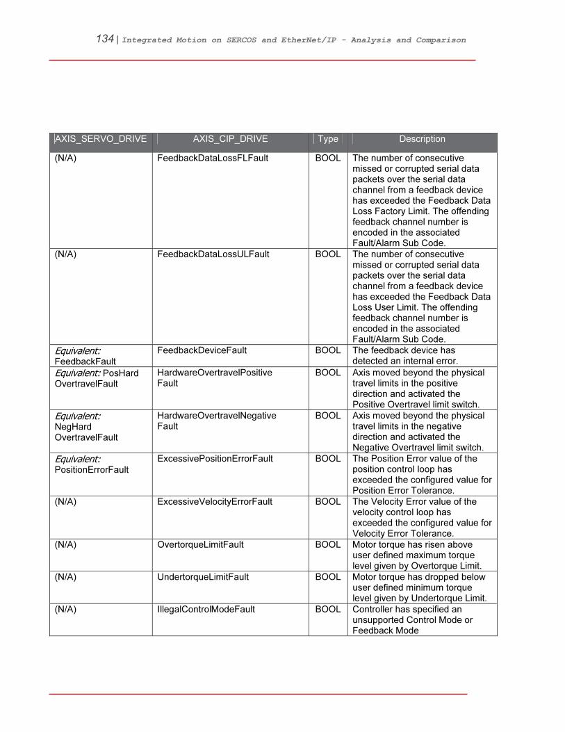
134 | Integrated Motion on SERCOS and EtherNet/IP - Analysis and Comparison
AXIS_SERVO_DRIVE AXIS_CIP_DRIVE Type Description
(N/A) FeedbackDataLossFLFault BOOL The number of consecutive missed or corrupted serial data packets over the serial data channel from a feedback device has exceeded the Feedback Data Loss Factory Limit. The offending feedback channel number is encoded in the associated Fault/Alarm Sub Code.
(N/A) FeedbackDataLossULFault BOOL The number of consecutive missed or corrupted serial data packets over the serial data channel from a feedback device has exceeded the Feedback Data Loss User Limit. The offending feedback channel number is encoded in the associated Fault/Alarm Sub Code.
Equivalent: FeedbackFault
FeedbackDeviceFault BOOL The feedback device has detected an internal error.
Equivalent: PosHard OvertravelFault
HardwareOvertravelPositive Fault
BOOL Axis moved beyond the physical travel limits in the positive direction and activated the Positive Overtravel limit switch.
Equivalent: NegHard OvertravelFault
HardwareOvertravelNegative Fault
BOOL Axis moved beyond the physical travel limits in the negative direction and activated the Negative Overtravel limit switch.
Equivalent: PositionErrorFault
ExcessivePositionErrorFault BOOL The Position Error value of the position control loop has exceeded the configured value for Position Error Tolerance.
(N/A) ExcessiveVelocityErrorFault BOOL The Velocity Error value of the velocity control loop has exceeded the configured value for Velocity Error Tolerance.
(N/A) OvertorqueLimitFault BOOL Motor torque has risen above user defined maximum torque level given by Overtorque Limit.
(N/A) UndertorqueLimitFault BOOL Motor torque has dropped below user defined minimum torque level given by Undertorque Limit.
(N/A) IllegalControlModeFault BOOL Controller has specified an unsupported Control Mode or Feedback Mode

135 | Integrated Motion on SERCOS and EtherNet/IP - Analysis and Comparison
AXIS_SERVO_DRIVE AXIS_CIP_DRIVE Type Description
Equivalent: DriveEnableInput Fault
EnableInputDeactivatedFault BOOL Enable has been deactivated while the axis is in Running state.
(N/A) ControllerInitiatedFault BOOL Exception generated specifically by controller.
(N/A) ExternalInputFault BOOL Exception generated by external input to device.
(N/A) CIPAxisFaultsRA LINT A bit map that represents the state of all manufacturer specific runtime faults. Fault bits when set are latched until a fault reset occurs. A fault reset clears the runtime fault bits, but the bits set again immediately if the underlying exception condition is still present. Any exceptions whose Axis Exception Action is configured to ignore or report as alarms do not appear in this attribute.
(N/A) CommutationStartupFault BOOL The self-sensing commutation startup algorithm failed.
(N/A) MotorVoltageMismatchFault BOOL The motor voltage is incompatible with the applied drive voltage.
(N/A) FeedbackFilterNoiseFault BOOL Excessive levels of noise have been detected by the digital feedback filter.
(N/A) FeedbackBatteryLossFault BOOL The battery voltage on a battery-backed motor encoder is low enough such that absolute position is not longer available.
(N/A) FeedbackBatteryLowFault BOOL The battery voltage on a battery-backed motor encoder is below a caution level.
(N/A) FeedbackIncrementalCountErrorFault
BOOL The periodic check of the incremental encoder position against the absolute encoder position or Hall edges indicates they are out of tolerance.
(N/A) ControlModuleOvertemperatureFLFault
BOOL Kinetix: The control module temperature has exceeded its limit. PF755: The temperature sensor on the Main Control Board detected excessive heat.
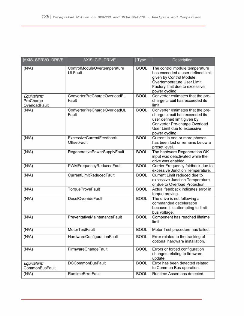
136 | Integrated Motion on SERCOS and EtherNet/IP - Analysis and Comparison
AXIS_SERVO_DRIVE AXIS_CIP_DRIVE Type Description
(N/A) ControlModuleOvertemperature ULFault
BOOL The control module temperature has exceeded a user defined limit given by Control Module Overtemperature User Limit. Factory limit due to excessive power cycling.
Equivalent: PreCharge OverloadFault
ConverterPreChargeOverloadFL Fault
BOOL Converter estimates that the pre-charge circuit has exceeded its limit.
(N/A) ConverterPreChargeOverloadUL Fault
BOOL Converter estimates that the pre-charge circuit has exceeded its user defined limit given by Converter Pre-charge Overload User Limit due to excessive power cycling.
(N/A) ExcessiveCurrentFeedback OffsetFault
BOOL Current in one or more phases has been lost or remains below a preset level.
(N/A) RegenerativePowerSupplyFault BOOL The hardware Regeneration OK input was deactivated while the drive was enabled.
(N/A) PWMFrequencyReducedFault BOOL Carrier Frequency foldback due to excessive Junction Temperature.
(N/A) CurrentLimitReducedFault BOOL Current Limit reduced due to excessive Junction Temperature or due to Overload Protection.
(N/A) TorqueProveFault BOOL Actual feedback indicates error in torque proving.
(N/A) DecelOverrideFault BOOL The drive is not following a commanded deceleration because it is attempting to limit bus voltage.
(N/A) PreventativeMaintenanceFault BOOL Component has reached lifetime limit.
(N/A) MotorTestFault BOOL Motor Test procedure has failed.
(N/A) HardwareConfigurationFault BOOL Error related to the tracking of optional hardware installation.
(N/A) FirmwareChangeFault BOOL Errors or forced configuration changes relating to firmware update.
Equivalent: CommonBusFault
DCCommonBusFault BOOL Error has been detected related to Common Bus operation.
(N/A) RuntimeErrorFault BOOL Runtime Assertions detected.
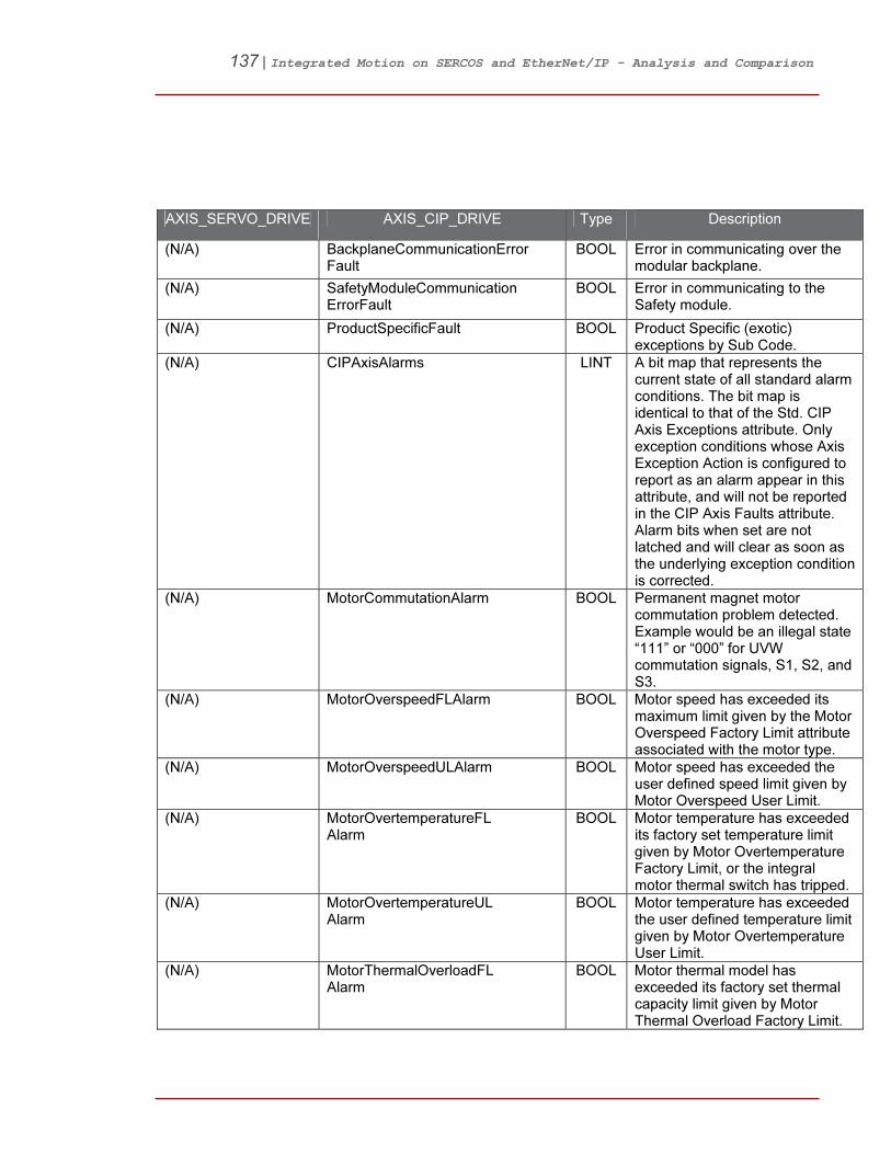
137 | Integrated Motion on SERCOS and EtherNet/IP - Analysis and Comparison
AXIS_SERVO_DRIVE AXIS_CIP_DRIVE Type Description
(N/A) BackplaneCommunicationError Fault
BOOL Error in communicating over the modular backplane.
(N/A) SafetyModuleCommunication ErrorFault
BOOL Error in communicating to the Safety module.
(N/A) ProductSpecificFault BOOL Product Specific (exotic) exceptions by Sub Code.
(N/A) CIPAxisAlarms LINT A bit map that represents the current state of all standard alarm conditions. The bit map is identical to that of the Std. CIP Axis Exceptions attribute. Only exception conditions whose Axis Exception Action is configured to report as an alarm appear in this attribute, and will not be reported in the CIP Axis Faults attribute. Alarm bits when set are not latched and will clear as soon as the underlying exception condition is corrected.
(N/A) MotorCommutationAlarm BOOL Permanent magnet motor commutation problem detected. Example would be an illegal state “111” or “000” for UVW commutation signals, S1, S2, and S3.
(N/A) MotorOverspeedFLAlarm BOOL Motor speed has exceeded its maximum limit given by the Motor Overspeed Factory Limit attribute associated with the motor type.
(N/A) MotorOverspeedULAlarm BOOL Motor speed has exceeded the user defined speed limit given by Motor Overspeed User Limit.
(N/A) MotorOvertemperatureFL Alarm
BOOL Motor temperature has exceeded its factory set temperature limit given by Motor Overtemperature Factory Limit, or the integral motor thermal switch has tripped.
(N/A) MotorOvertemperatureUL Alarm
BOOL Motor temperature has exceeded the user defined temperature limit given by Motor Overtemperature User Limit.
(N/A) MotorThermalOverloadFL Alarm
BOOL Motor thermal model has exceeded its factory set thermal capacity limit given by Motor Thermal Overload Factory Limit.

138 | Integrated Motion on SERCOS and EtherNet/IP - Analysis and Comparison
AXIS_SERVO_DRIVE AXIS_CIP_DRIVE Type Description
(N/A) MotorThermalOverloadUL Alarm
BOOL Motor thermal model has exceeded its user defined thermal capacity given by Motor Thermal Overload User Limit.
(N/A) InverterOvercurrentAlarm BOOL Inverter current has exceeded the factory set peak or instantaneous current limit.
(N/A) InverterOvertemperatureFL Alarm
BOOL Inverter temperature has exceeded its factory set temperature limit given by Inverter Overtemperature Factory Limit.
(N/A) InverterOvertemperatureUL Alarm
BOOL Inverter temperature has exceeded the user defined temperature limit given by Inverter Overtemperature User Limit.
(N/A) InverterThermalOverloadFL Alarm
BOOL Inverter thermal model has exceeded its factory set thermal capacity limit given by Inverter Thermal Overload Factory Limit.
(N/A) InverterThermalOverloadUL Alarm
BOOL Inverter thermal model has exceeded its user defined thermal capacity given by Inverter Thermal Overload User Limit.
(N/A) ConverterGroundCurrentFL Alarm
BOOL Ground Current has exceeded its factory set current limit given by Converter Ground Current Factory Limit.
(N/A) ConverterGroundCurrentUL Alarm
BOOL Ground Current has exceeded user defined limit given by Converter Ground Current User Limit.
(N/A) ConverterOvertemperatureFL Alarm
BOOL Converter temperature has exceeded its factory set temperature limit given by Converter Overtemperature Factory Limit.
(N/A) ConverterOvertemperatureUL Alarm
BOOL Converter temperature has exceeded the user defined temperature limit given by Converter Overtemperature User Limit.
(N/A) ConverterThermalOverloadFL Alarm
BOOL Converter thermal model has exceeded its factory set thermal capacity limit given by Converter Thermal Overload Factory Limit.

139 | Integrated Motion on SERCOS and EtherNet/IP - Analysis and Comparison
AXIS_SERVO_DRIVE AXIS_CIP_DRIVE Type Description
(N/A) ConverterThermalOverloadUL Alarm
BOOL Converter thermal model has exceeded its user defined thermal capacity given by Converter Thermal Overload User Limit.
(N/A) ConverterACPowerLossAlarm BOOL Multiple AC phases have been lost on the AC line to the converter.
(N/A) ConverterACSinglePhaseLoss Alarm
BOOL One AC phase has been lost on the AC line to the converter.
(N/A) ConverterACPhaseShortAlarm BOOL A short has been detected between an AC phase and another AC phase or ground.
(N/A) ConverterPreChargeAlarm BOOL A problem has been detected in the Converter’s Pre-Charge circuitry preventing the DC Bus from charging to an acceptable voltage level.
(N/A) BusRegulatorOvertemperature FLAlarm
BOOL Bus Regulator temperature has exceeded its factory set temperature limit given by Bus Regulator Overtemperature Factory Limit.
(N/A) BusRegulatorOvertemperature ULAlarm
BOOL Bus Regulator temperature has exceeded the user defined temperature limit given by Bus Regulator Overtemperature User Limit.
(N/A) BusRegulatorThermalOverload FLAlarm
BOOL Bus Regulator thermal model has exceeded its factory set thermal capacity limit given by Bus Regulator Thermal Overload Factory Limit.
(N/A) BusRegulatorThermalOverload ULAlarm
BOOL Bus Regulator thermal model has exceeded its user defined thermal capacity given by Bus Regulator Thermal Overload User Limit.
(N/A) BusRegulatorAlarm BOOL The bus regulator (shunt) module in a multi-axis system has failed.
(N/A) BusUndervoltageFLAlarm BOOL DC Bus voltage level is below the factory set limit given by Bus Undervoltage Factory Limit.
(N/A) BusUndervoltageULAlarm BOOL DC Bus voltage level is below user defined limit given by Bus Undervoltage User Limit.
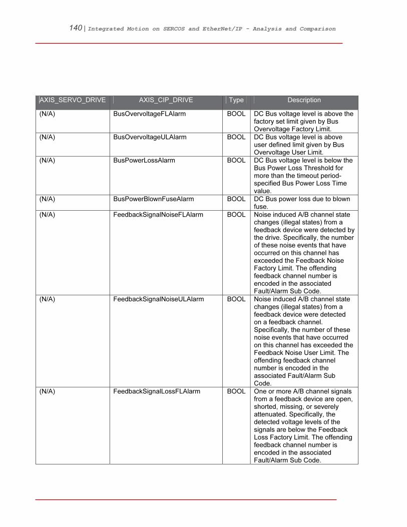
140 | Integrated Motion on SERCOS and EtherNet/IP - Analysis and Comparison
AXIS_SERVO_DRIVE AXIS_CIP_DRIVE Type Description
(N/A) BusOvervoltageFLAlarm BOOL DC Bus voltage level is above the factory set limit given by Bus Overvoltage Factory Limit.
(N/A) BusOvervoltageULAlarm BOOL DC Bus voltage level is above user defined limit given by Bus Overvoltage User Limit.
(N/A) BusPowerLossAlarm BOOL DC Bus voltage level is below the Bus Power Loss Threshold for more than the timeout period-specified Bus Power Loss Time value.
(N/A) BusPowerBlownFuseAlarm BOOL DC Bus power loss due to blown fuse.
(N/A) FeedbackSignalNoiseFLAlarm BOOL Noise induced A/B channel state changes (illegal states) from a feedback device were detected by the drive. Specifically, the number of these noise events that have occurred on this channel has exceeded the Feedback Noise Factory Limit. The offending feedback channel number is encoded in the associated Fault/Alarm Sub Code.
(N/A) FeedbackSignalNoiseULAlarm BOOL Noise induced A/B channel state changes (illegal states) from a feedback device were detected on a feedback channel. Specifically, the number of these noise events that have occurred on this channel has exceeded the Feedback Noise User Limit. The offending feedback channel number is encoded in the associated Fault/Alarm Sub Code.
(N/A) FeedbackSignalLossFLAlarm BOOL One or more A/B channel signals from a feedback device are open, shorted, missing, or severely attenuated. Specifically, the detected voltage levels of the signals are below the Feedback Loss Factory Limit. The offending feedback channel number is encoded in the associated Fault/Alarm Sub Code.

141 | Integrated Motion on SERCOS and EtherNet/IP - Analysis and Comparison
AXIS_SERVO_DRIVE AXIS_CIP_DRIVE Type Description
(N/A) FeedbackSignalLossULAlarm BOOL One or more A/B channel signals from a feedback device are open, shorted, missing, or severely attenuated. Specifically, the detected voltage levels of the signals are below the Feedback Loss User Limit. The offending feedback channel number is encoded in the associated Fault/Alarm Sub Code.
(N/A) FeedbackDataLossFLAlarm BOOL The number of consecutive missed or corrupted serial data packets over the serial data channel from a feedback device has exceeded the Feedback Data Loss Factory Limit. The offending feedback channel number is encoded in the associated Fault/Alarm Sub Code.
(N/A) FeedbackDataLossULAlarm BOOL The number of consecutive missed or corrupted serial data packets over the serial data channel from a feedback device has exceeded the Feedback Data Loss User Limit. The offending feedback channel number is encoded in the associated Fault/Alarm Sub Code.
(N/A) FeedbackDeviceAlarm BOOL The feedback device has detected an internal error.
(N/A) HardwareOvertravelPositive Alarm
BOOL Axis moved beyond the physical travel limits in the positive direction and activated the Positive Overtravel limit switch.
(N/A) HardwareOvertravelNegative Alarm
BOOL Axis moved beyond the physical travel limits in the negative direction and activated the Negative Overtravel limit switch.
(N/A) ExcessivePositionErrorAlarm BOOL The Position Error value of the position control loop has exceeded the configured value for Position Error Tolerance.
(N/A) ExcessiveVelocityErrorAlarm BOOL The Velocity Error value of the velocity control loop has exceeded the configured value for Velocity Error Tolerance.

142 | Integrated Motion on SERCOS and EtherNet/IP - Analysis and Comparison
AXIS_SERVO_DRIVE AXIS_CIP_DRIVE Type Description
(N/A) OvertorqueLimitAlarm BOOL Motor torque has risen above user defined maximum torque level given by Overtorque Limit.
(N/A) UndertorqueLimitAlarm BOOL Motor torque has dropped below user defined minimum torque level given by Undertorque Limit.
(N/A) IllegalControlModeAlarm BOOL Controller has specified an unsupported Control Mode or Feedback Mode.
(N/A) EnableInputDeactivatedAlarm BOOL Enable has been deactivated while the axis is in Running state.
(N/A) ControllerInitiatedAlarm BOOL Exception generated specifically by controller.
(N/A) ExternalInputAlarm BOOL Exception generated by external input to device.
(N/A) CIPAxisAlarmsRA LINT A bit map that represents the current state of all manufacturer specific alarm conditions. Only exception conditions whose Axis Exception Action is configured to report as an alarm appear in this attribute, and will not be reported in the CIP Axis Faults attribute. Alarm bits when set are not latched and will clear as soon as the underlying exception condition is corrected.
(N/A) CommutationStartupAlarm BOOL The self-sensing commutation startup algorithm failed.
(N/A) MotorVoltageMismatchAlarm BOOL The motor voltage is incompatible with the applied drive voltage.
(N/A) FeedbackFilterNoiseAlarm BOOL Excessive levels of noise have been detected by the digital feedback filter.
(N/A) FeedbackBatteryLossAlarm BOOL The battery voltage on a battery-backed motor encoder is low enough such that absolute position is not longer available.
(N/A) FeedbackBatteryLowAlarm BOOL The battery voltage on a battery-backed motor encoder is below a caution level.
(N/A) FeedbackIncrementalCount ErrorAlarm
BOOL The periodic check of the incremental encoder position against the absolute encoder position or Hall edges indicates they are out of tolerance.
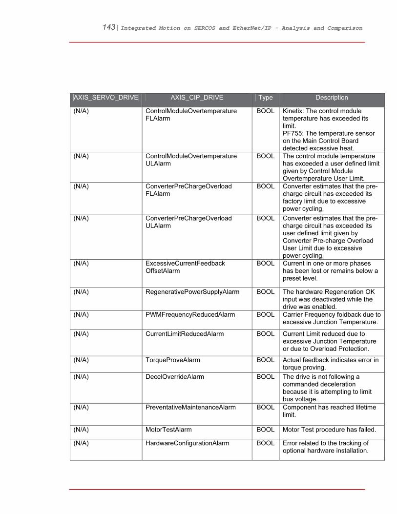
143 | Integrated Motion on SERCOS and EtherNet/IP - Analysis and Comparison
AXIS_SERVO_DRIVE AXIS_CIP_DRIVE Type Description
(N/A) ControlModuleOvertemperature FLAlarm
BOOL Kinetix: The control module temperature has exceeded its limit. PF755: The temperature sensor on the Main Control Board detected excessive heat.
(N/A) ControlModuleOvertemperature ULAlarm
BOOL The control module temperature has exceeded a user defined limit given by Control Module Overtemperature User Limit.
(N/A) ConverterPreChargeOverload FLAlarm
BOOL Converter estimates that the pre-charge circuit has exceeded its factory limit due to excessive power cycling.
(N/A) ConverterPreChargeOverload ULAlarm
BOOL Converter estimates that the pre-charge circuit has exceeded its user defined limit given by Converter Pre-charge Overload User Limit due to excessive power cycling.
(N/A) ExcessiveCurrentFeedback OffsetAlarm
BOOL Current in one or more phases has been lost or remains below a preset level.
(N/A) RegenerativePowerSupplyAlarm BOOL The hardware Regeneration OK input was deactivated while the drive was enabled.
(N/A) PWMFrequencyReducedAlarm BOOL Carrier Frequency foldback due to excessive Junction Temperature.
(N/A) CurrentLimitReducedAlarm BOOL Current Limit reduced due to excessive Junction Temperature or due to Overload Protection.
(N/A) TorqueProveAlarm BOOL Actual feedback indicates error in torque proving.
(N/A) DecelOverrideAlarm BOOL The drive is not following a commanded deceleration because it is attempting to limit bus voltage.
(N/A) PreventativeMaintenanceAlarm BOOL Component has reached lifetime limit.
(N/A) MotorTestAlarm BOOL Motor Test procedure has failed.
(N/A) HardwareConfigurationAlarm BOOL Error related to the tracking of optional hardware installation.

144 | Integrated Motion on SERCOS and EtherNet/IP - Analysis and Comparison
AXIS_SERVO_DRIVE AXIS_CIP_DRIVE Type Description
(N/A) FirmwareChangeAlarm BOOL Errors or forced configuration changes relating to firmware update.
(N/A) DCCommonBusAlarm BOOL Error has been detected related to Common Bus operation.
(N/A) RuntimeErrorAlarm BOOL Runtime Assertions detected.
(N/A) BackplaneCommunicationError Alarm
BOOL Error in communicating over the modular backplane.
(N/A) SafetyModuleCommunication ErrorAlarm
BOOL Error in communicating to the Safety module.
(N/A) ProductSpecificAlarm BOOL Product Specific (exotic) exceptions by Sub Code.
(N/A) CIPInitializationFaults DINT A bit map that represents the state of all standard initialization faults. These faults prevent any motion, and do not have configurable fault actions. Examples of initialization faults are corrupted memory data, calibration errors, firmware startup problems, or an invalid configuration attribute value. Initialization faults cannot be cleared with a Fault Reset service, although a power-cycle provides a new attempt at initialization.
(N/A) BootBlockChecksumFault BOOL Checksum or CRC error for Boot Block of CIP Motion device detected as part of Self-Test.
(N/A) MainBlockChecksumFault BOOL Checksum or CRC error for Main Block of CIP Motion device detected as part of Self-Test.
(N/A) NonvolatileMemoryChecksum Fault
BOOL Checksum or CRC error for NV Memory of CIP Motion device detected as part of Self-Test.

145 | Integrated Motion on SERCOS and EtherNet/IP - Analysis and Comparison
AXIS_SERVO_DRIVE AXIS_CIP_DRIVE Type Description
(N/A) CIPInitializationFaultsRA DINT A bit map that represents the state of all Rockwell Automation specific initialization faults. These faults prevent any motion, and do not have configurable fault actions. Examples of initialization faults are corrupted memory data, calibration errors, firmware startup problems, or an invalid configuration attribute value. Initialization faults cannot be cleared with a Fault Reset service, although a power-cycle provides a new attempt at initialization.
(N/A) FeedbackDataCorruptionFault BOOL Smart Encoder Data Corruption detected.
(N/A) FeedbackDataRangeFault BOOL Data within a motor data blob is out of range.
(N/A) FeedbackCommunication StartupFault
BOOL Communications with a smart encoder could not be established.
(N/A) FeedbackAbsoluteOverspeed Fault
BOOL Excessive speed was detected in the battery-backed encoder while power was off.
(N/A) FeedbackAbsolutePowerOff TravelFault
BOOL The power-off travel range of the battery-backed encoder has been exceeded.
(N/A) FeedbackAbsoluteStartup SpeedFault
BOOL The absolute encoder was not able to accurately determine the position after power-up due to speed greater than 100 RPM.
(N/A) CommutationOffset UninitializedFault
BOOL The commutation offset stored in a third-party motor has not been initialized.
(N/A) InvalidFPGAImageFault BOOL The FPGA image is incompatible with hardware operation.
(N/A) InvalidBoardSupportPackage Fault
BOOL The board support package is incompatible with hardware operation.
(N/A) InvalidSafetyFirmwareFault BOOL The safety firmware is not compatible with the drive firmware, or the main safety firmware is missing.
(N/A) PowerBoardFault BOOL Power Board checksum error.

146 | Integrated Motion on SERCOS and EtherNet/IP - Analysis and Comparison
AXIS_SERVO_DRIVE AXIS_CIP_DRIVE Type Description
(N/A) IllegalOptionCardFault BOOL The Main Control Board has detected an illegal option installed in the port.
(N/A) OptionStorageChecksumFault BOOL Option data storage checksum failed.
Equivalent: DriveControlVoltageFault
ModuleVoltageMismatchFault BOOL IAM detects a voltage rating mismatch on the modular backplane.
(N/A) UnknownModuleFault BOOL Unknown module is detected on the modular backplane.
(N/A) FactoryConfigurationErrorFault BOOL Factory Configuration Data is missing or invalid.
(N/A) IllegalAddressFault BOOL AM Node Address is out of range (>254).
(N/A) SeriesMismatchFault BOOL SERCOS AMs have been detected by the CIP IAM.
(N/A) OpenSlotFault BOOL IAM detects an open slot on the modular backplane.
(N/A) CIPStartInhibits INT A bit map that specifies the current state of all standard conditions that inhibits starting of the axis.
(N/A) AxisEnableInputInhibit BOOL Axis Enable Input is not active.
(N/A) MotorNotConfiguredInhibit BOOL The associated motor has not been configured for use.
(N/A) FeedbackNotConfiguredInhibit BOOL The associated feedback device has not been configured for use.
(N/A) CIPStartInhibitsRA INT A bit map that specifies the current state of all Rockwell Automation specific conditions that inhibits starting of the axis.
(N/A) VoltsHertzCurveDefinition Inhibit
BOOL Conflict exists in the V/Hz curve definition.
(N/A) MotorFeedbackRequiredInhibit BOOL Can't run using the selected motor control mode with Primary Feedback or Alternate Feedback set as open loop.
(N/A) SpeedLimitConfiguration Inhibit
BOOL Speed Ref Limit Conflict, either Minimum Forward Speed Limit exceeds Maximum Forward Speed Limit, or Minimum Reverse Speed Limit exceeds Maximum Reverse Speed Limit.

147 | Integrated Motion on SERCOS and EtherNet/IP - Analysis and Comparison
AXIS_SERVO_DRIVE AXIS_CIP_DRIVE Type Description
(N/A) TorqueProveConfiguration Inhibit
BOOL When Torque Prove Config is enabled, Control Mode, Feedback Mode, Motor Feedback Type, and Motor Option Configuration must be properly set.
(N/A) SafeTorqueOffInhibit BOOL The safety function has disabled the power structure.
(N/A) SafetyResetRequiredInhibit BOOL The safety reset input needs to be toggled before the safety board will allow motion again.
(N/A) SafetyNotConfiguredInhibit BOOL The embedded safety function of the drive has not been configured.

148 | Integrated Motion on SERCOS and EtherNet/IP - Analysis and Comparison
9BAdditional Resources
All publications can be found online www.rockwellautomation.com/literature
Kinetix 6200 and Kinetix 6500 Modular Multi-axis Servo Drives User Manual
2094-UM002…
Kinetix 6200 and Kinetix 6500 Safe Speed Monitoring Safety Reference Manual
2094-RM001…
CIP Motion Configuration and Startup User Manual
MOTION-UM003…
Kinetix Motion Control Selection Guide GMC-SG001…
CIP Motion Popular Configuration Drawing Without notes
IASIMP-QR020…
CIP Motion Reference Manual MOTION-RM003…
All publications can be found online www.rockwellautomation.com

149 | Integrated Motion on SERCOS and EtherNet/IP - Analysis and Comparison
Allen-Bradley, Rockwell Automation, Kinetix®, PowerFlex®, ControlLogix®, ArmorBlock®, Stratix™ 2000, Stratix™ 6000, Stratix™ 8000, RSLinx, RSLogix™ are trademarks of Rockwell Automation.
Trademarks not belonging to Rockwell Automation are property of their respective companies.
For more information refer to our web site: www.ab.com/motion
www.rockwellautomation.com www.ab.com
Corporate Headquarters
Rockwell Automation, 777 East Wisconsin Avenue, Suite 1400, Milwaukee, WI, 53202-5302 USA, Tel: (1) 414.212.5200, Fax: (1)
414.212.5201
20BHeadquarters for Allen-Bradley Products, Rockwell Software Products and Global Manufacturing Solutions Americas: Rockwell Automation, 1201 South Second Street, Milwaukee, WI 53204-2496 USA, Tel: (1) 414.382.2000, Fax: (1)
414.382.4444
Europe: Rockwell Automation SA/NV, Vorstlaan/Boulevard du Souverain 36-BP 3A/B, 1170 Brussels, Belgium, Tel: (32) 2 663 0600, Fax:
(32) 2 663 0640 Asia Pacific: Rockwell Automation, 27/F Citicorp Centre, 18 Whitfield Road, Causeway Bay, Hong Kong, Tel: (852) 2887 4788, Fax: (852) 2508 1846 Publication MOTION-WP001A-EN-P – April 2011 Copyright © 2011 Rockwell Automation, Inc. All Rights Reserved. Printed in USA.