
Integrated HST (Pump and Motor) Integrated HST (Pump & …29 HST 30 HST Basic Construction...
6
29 HST Basic Construction Integrated HST (Pump & Motor) Basic Characteristics HST stands for Hydrostatic Transmission and is used in a travel system to connect the hydraulic pump with the motor in a closed circuit enabling continuous speed change from Forward to Stop/Neutral and Reverse or vice versa. HST is smoother in operation and smaller in size than mechanical transmissions installed on automobiles. ■ Output Horsepower characteristic ■ Output Speed characteristics ① Theoretical output speed: (Pump displacement)/(motor displacement) × (Input speed) ② Actual speed: (Theoretical output speed) × (Volumetric efficiency) ③ Theoretical output torque: (Motor displacement) × (HST load pressure) ■ Output torque characteristic ■ Servo Regulator (Manual Operation) [SL] Lever operation torque characteristic ■ Servo Regulator (Electric Control) [EL] ● HVFD18F-R35 Circuit example Ampere - Output speed characteristics HVFD37F-R35-SL example
Transcript of Integrated HST (Pump and Motor) Integrated HST (Pump & …29 HST 30 HST Basic Construction...

29
HST
30
HST
Basic Construction
Integrated HST (Pump & Motor)
Basic Characteristics
Main Mechanism
HST stands for Hydrostatic Transmission and is used in a travel system to connect the hydraulic pump with the motor in a closed circuit enabling continuous speed change from Forward to Stop/Neutral and Reverse or vice versa. HST is smoother in operation and smaller in size than mechanical transmissions installed on automobiles.
■ Output Horsepower characteristic ■ Output Speed characteristics
① Theoretical output speed: (Pump displacement)/(motor displacement)×(Input speed)② Actual speed: (Theoretical output speed)×(Volumetric efficiency)③ Theoretical output torque: (Motor displacement)×(HST load pressure)
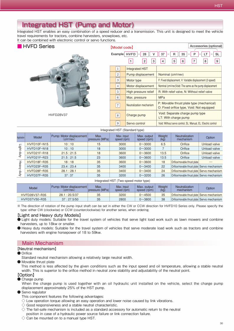
Integrated HST (Pump and Motor)Integrated HST enables an easy combination of a speed reducer and a transmission. This unit is designed to meet the vehicle travel requirements for tractors, combine harvesters, snowplows, etc. It can be combined with electronic control or servo functions.
【Neutral mechanism】● Orifice Standard neutral mechanism allowing a relatively large neutral width.● Movable thrust plate This method is less affected by the given conditions such as the input speed and oil temperature, allowing a stable neutral
width. This is superior to the orifice method in neutral zone stability and adjustability of the neutral point.【Option】 ● Charge pump When the charge pump is used together with an oil hydraulic unit installed on the vehicle, select the charge pump
displacement approximately 25% of the HST pump.● Servo regulator
This component features the following advantages:◇ Low operation torque allowing an easy operation and lower noise caused by link vibrations.◇ Good responsiveness and a stable neutral characteristic.◇ The fail-safe mechanism is included as a standard accessory for automatic return to the neutral position in case of a hydraulic power source failure or link connection failure.◇ Can be mounted on to a manual type HST.
■ Output torque characteristic
【Light and Heavy duty Models】● Light duty models: Suitable for the travel system of vehicles that serve light load work such as lawn mowers and combine
harvesters, up to 18kw or smaller.● Heavy duty models: Suitable for the travel system of vehicles that serve moderate load work such as tractors and combine
harvesters with engine horsepower of 18 to 59kw.
※ The direction of rotation of the pump input shaft can be set in either the CW or CCW direction for HVFD10 Series only. Please specify the type: either CW (clockwise) or CCW (counterclockwise) for another series, when ordering.
HVFD28V37
■ Servo Regulator (Manual Operation) [SL] Lever operation torque characteristic
■ Servo Regulator (Electric Control) [EL]
● HVFD18F-R35 Circuit example
Ampere - Output speed characteristicsHVFD37F-R35-SL example
■ HVFD Series
29
HST
30
HST
Basic Construction
Integrated HST (Pump & Motor)
Basic Characteristics
Main Mechanism
HST stands for Hydrostatic Transmission and is used in a travel system to connect the hydraulic pump with the motor in a closed circuit enabling continuous speed change from Forward to Stop/Neutral and Reverse or vice versa. HST is smoother in operation and smaller in size than mechanical transmissions installed on automobiles.
■ Output Horsepower characteristic ■ Output Speed characteristics
① Theoretical output speed: (Pump displacement)/(motor displacement)×(Input speed)② Actual speed: (Theoretical output speed)×(Volumetric efficiency)③ Theoretical output torque: (Motor displacement)×(HST load pressure)
Integrated HST (Pump and Motor)Integrated HST enables an easy combination of a speed reducer and a transmission. This unit is designed to meet the vehicle travel requirements for tractors, combine harvesters, snowplows, etc. It can be combined with electronic control or servo functions.
【Neutral mechanism】● Orifice Standard neutral mechanism allowing a relatively large neutral width.● Movable thrust plate This method is less affected by the given conditions such as the input speed and oil temperature, allowing a stable neutral
width. This is superior to the orifice method in neutral zone stability and adjustability of the neutral point.【Option】 ● Charge pump When the charge pump is used together with an oil hydraulic unit installed on the vehicle, select the charge pump
displacement approximately 25% of the HST pump.● Servo regulator
This component features the following advantages:◇ Low operation torque allowing an easy operation and lower noise caused by link vibrations.◇ Good responsiveness and a stable neutral characteristic.◇ The fail-safe mechanism is included as a standard accessory for automatic return to the neutral position in case of a hydraulic power source failure or link connection failure.◇ Can be mounted on to a manual type HST.
■ Output torque characteristic
【Light and Heavy duty Models】● Light duty models: Suitable for the travel system of vehicles that serve light load work such as lawn mowers and combine
harvesters, up to 18kw or smaller.● Heavy duty models: Suitable for the travel system of vehicles that serve moderate load work such as tractors and combine
harvesters with engine horsepower of 18 to 59kw.
※ The direction of rotation of the pump input shaft can be set in either the CW or CCW direction for HVFD10 Series only. Please specify the type: either CW (clockwise) or CCW (counterclockwise) for another series, when ordering.
HVFD28V37
■ Servo Regulator (Manual Operation) [SL] Lever operation torque characteristic
■ Servo Regulator (Electric Control) [EL]
● HVFD18F-R35 Circuit example
Ampere - Output speed characteristicsHVFD37F-R35-SL example
■ HVFD Series
31
HST
32
HST
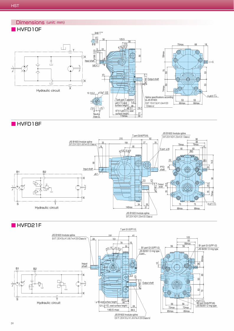
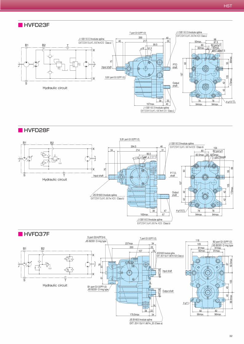
Dimensions (unit: mm)
■ HVFD10F
Hydraulic circuit
■ HVFD18F
Hydraulic circuit
■ HVFD21F
Hydraulic circuit
■ HVFD23F
Hydraulic circuit
■ HVFD28F
Hydraulic circuit
■ HVFD37F
Hydraulic circuit
31
HST
32
HST
Dimensions (unit: mm)
■ HVFD10F
Hydraulic circuit
■ HVFD18F
Hydraulic circuit
■ HVFD21F
Hydraulic circuit
■ HVFD23F
Hydraulic circuit
■ HVFD28F
Hydraulic circuit
■ HVFD37F
Hydraulic circuit
33
HST
34
HST
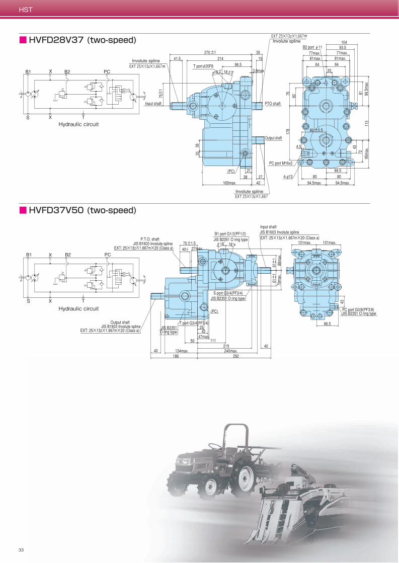
■ HVFD28V37 (two-speed)
Hydraulic circuit
■ HVFD37V50 (two-speed)
Hydraulic circuit
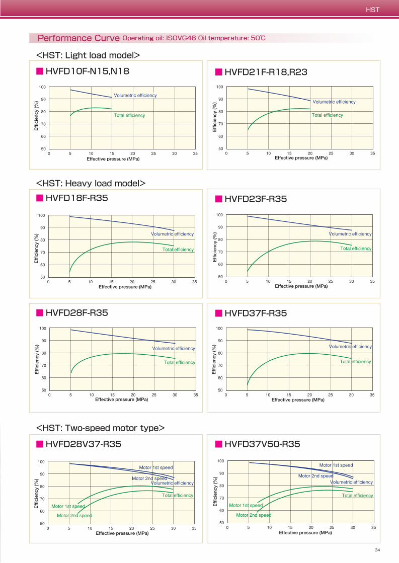
Performance Curve Operating oil: ISOVG46 Oil temperature: 50℃
<HST: Light load model>
■ HVFD23F-R35
■ HVFD28F-R35 ■ HVFD37F-R35
■ HVFD21F-R18,R23
■ HVFD37V50-R35
■ HVFD10F-N15,N18
<HST: Heavy load model>
■ HVFD18F-R35
<HST: Two-speed motor type>
■ HVFD28V37-R35
33
HST
34
HST
■ HVFD28V37 (two-speed)
Hydraulic circuit
■ HVFD37V50 (two-speed)
Hydraulic circuit
Performance Curve Operating oil: ISOVG46 Oil temperature: 50℃
<HST: Light load model>
■ HVFD23F-R35
■ HVFD28F-R35 ■ HVFD37F-R35
■ HVFD21F-R18,R23
■ HVFD37V50-R35
■ HVFD10F-N15,N18
<HST: Heavy load model>
■ HVFD18F-R35
<HST: Two-speed motor type>
■ HVFD28V37-R35