Integral SVR-PRO 100 SRI 2.5” SATA 6Gbps SSD regardless of the state of the Attribute Autosave...
22
i Product Specification PRODUCT OVERVIEW Delivers solid I/O cost-to-performance benefits for applications that demand low latency read speeds and greater bandwidth for server and storage environments for Serial Advanced Technology Attachment (SATA)-based systems in capacities of 480GB, 960GB, 4TB and 8TB. Uses a single-chip controller with a SATA interface on the system side and 8-channels of Flash internally. The industry- standard 2.5-inch form factor enables interchangeability with existing hard disk drives (HDDs) and native SATA HDD drop-in replacement with the enhanced performance, reliability, ruggedness, and power savings offered by an SSD. SVR-PRO 100 has the capacity you require for storage-hungry SATA based systems. BENEFITS • High capacity SSDs for big data storage (4TB and 8TB) • Designed for read intensive applications • Reduced latencies • Lower Power Consumption • Non-volatile Flash Memory for outstanding data retention - Less likely to fail than HDD • Shock resistance - No moving parts enable the product to be used in tougher conditions • Silent operation - Noiseless and low heat dissipation • Much less heat generated than conventional HDD FEATURES • 2.5” form factor with SATA III 6Gbps interface (backwards compatible with SATA 3Gbps and SATA 1.5Gbps) • Sequential Read up to 554MB/s and Write up 517MB/s 1 • Random Read IOPS up to 80K, Random Write up to 70K 3 • Supports S.M.A.R.T. - Self-Monitoring, Analysis and Reporting Technology • Features an internal temperature sensor with an accuracy of +/-2°C over a range of -40°C to +125°C which can be monitored using a SMART attribute BEh • The SSD hardware is built with a number of capacitors that ensure that the data in the write cache of the SSD is protected against corruption if a power loss was to occur, enabling the SSD to complete the last write command to the NAND flash • CE and FCC compliant • 5 Year Warranty or maximum endurance use. Rev:2 Integral SVR-PRO 100 SRI 2.5” SATA 6Gbps SSD INTRODUCTION The SVR-PRO 100 SRI SSD range is designed for Read intensive applications, offers up to a massive 8TB of data storage and features consistently low latency with a superior level of read and write IOPS, together with power loss protection. 8 TB 960 GB 4 TB 480 GB
Transcript of Integral SVR-PRO 100 SRI 2.5” SATA 6Gbps SSD regardless of the state of the Attribute Autosave...

i iProduct Specification
PRODUCT OVERVIEW
Delivers solid I/O cost-to-performance benefits for applications that demand low latency read speeds and greater bandwidth for server and storage environments for Serial Advanced Technology Attachment (SATA)-based systems in capacities of 480GB, 960GB, 4TB and 8TB.
Uses a single-chip controller with a SATA interface on the system side and 8-channels of Flash internally. The industry-standard 2.5-inch form factor enables interchangeability with existing hard disk drives (HDDs) and native SATA HDD drop-in replacement with the enhanced performance, reliability, ruggedness, and power savings offered by an SSD.
SVR-PRO 100 has the capacity you require for storage-hungry SATA based systems.
BENEFITS
• High capacity SSDs for big data storage (4TB and 8TB)
• Designed for read intensive applications
• Reduced latencies
• Lower Power Consumption
• Non-volatile Flash Memory for outstanding data retention - Less likely to fail than HDD
• Shock resistance - No moving parts enable the product to be used in tougher conditions
• Silent operation - Noiseless and low heat dissipation
• Much less heat generated than conventional HDD
FEATURES
• 2.5” form factor with SATA III 6Gbps interface (backwards compatible with SATA 3Gbps and SATA 1.5Gbps)
• Sequential Read up to 554MB/s and Write up 517MB/s1
• Random Read IOPS up to 80K, Random Write up to 70K3
• Supports S.M.A.R.T. - Self-Monitoring, Analysis and Reporting Technology
• Features an internal temperature sensor with an accuracy of +/-2°C over a range of -40°C to +125°C which can be monitored using a SMART attribute BEh
• The SSD hardware is built with a number of capacitors that ensure that the data in the write cache of the SSD is protected against corruption if a power loss was to occur, enabling the SSD to complete the last write command to the NAND flash
• CE and FCC compliant
• 5 Year Warranty or maximum endurance use.
Rev:2
Integral SVR-PRO 100 SRI 2.5” SATA 6Gbps SSD
INTRODUCTIONThe SVR-PRO 100 SRI SSD range is designed for Read intensive applications, offers up to a massive 8TB of data storage and features consistently low latency with a superior level of read and write IOPS, together with power loss protection.
8TB
960GB
4TB
480GB

i iProduct Specification: for 480GB, 960GB
CAPACITY PART CODE BARCODE (EAN)
480GB INSSD480GS625SVR1SRI 5055288437364
960GB INSSD960GS625SVR1SRI 5055288437371
Notes:
1. Actual performance may vary and depends on use conditions, host and environment
2. 4KB transfers used for Read/Write latency values.
3. Typical I/O performance numbers as measured fresh-out-of-the-box (FOB) using IOmeter with a queue depth 32 and write cache enabled.
4. Operating temperature is the drive case temperature as measured by the SMART temperature attribute
5. Mean Time Between Failures is estimated based on JEDEC-218/219 standard methodology.
6. TBW (Total bytes Written). DWPD (Drive Writes Per Day) TBW and DWPD is a measurement of SSDs expected lifespan, which represents the amount of data written to the device and DWPD. This is only an estimate and can differ based in user usage behaviour, platform and estimates provided by the flash vendor
7. Power Consumption may differ according to flash configuration and platform
All Specifications are subject to change without notice
1GB = 1,000,000,000 Bytes, 1TB = 1,000,000,000,000 Bytes; 1 sector = 512 Bytes.
The total usable capacity of the SSD may be less than the total physical capacity because a small portion of the capacity is used for NAND flash management and maintenance purposes.
Rev:2
CAPACITIES & INTERFACE
Capacities available 480GB and 960GB
Form Factor 2.5 Inch
InterfaceSATA III 6Gbps (also Compatible with SATA II 3Gbps and SATA 1.5Gbps)
Controller Novachips
NAND MLC
DIMENSIONS
Length mm 100.45
Width mm 69.85
Height mm 7mm
Weight 100g
Sequential Performance up to1 Read:520MB/s Write: 500MB/s
Random Performance3 Read 80K IOPS, Write 70K IOPS
Typical Latency2 Read: 65us, Write: 40us
Operating Temp4 0 to 70°C
Humidity 5% to 95%, non-condensing
POWER CONSUMPTION
Supply Voltage 4.5V minimum – 5.5V maximum
Power Consumption7
Active Maximum 128KB sequential write
480GB = 4700mW960GB = 5200mW
Idle AveragePower Consumptions7 145mW
Shock (operating and non operating) Maximum
1000G, duration 0.5ms
Vibration MaximumOperating 2.17 Grms (5-700Hz, Non-Operating 3.13 Grms (5-800Hz)
Supports SMART Yes
MTBF5 2 Million Hours
Endurance6 1 DWPD
WARRANTY 5 YEARS or Maximum endurance
Compliancy CE, FCC, RoHS
Bulk Weight 100g
Packaged Weight 158g
Packaged Dimensions (mm) L = 133 W = 117 H = 13

i iProduct Specification: for 480GB, 960GB
Rev:2
Physical Dimensions
(2.5” 7mm z-height)

i iProduct Specification: for 480GB, 960GB
Rev:2
COMMAND NAME COMMAND CODE (HEX)
CHECK POWER MODE E5h or 98h
DEVICE RESET 08h
DEVICE CONFIGURATION
DEVICE CONFIGURATION FREEZE LOCK B1h/C1h
DEVICE CONFIGURATION IDENTIFY B1h/C2h
DEVICE CONFIGURATION RESTORE B1h/C0h
DEVICE CONFIGURATION SET B1h/C3h
DOWNLOAD MICROCODE 92h
DATA SET MANAGEMENT 06h
EXECUTE DEVICE DIAGNOSTIC 90h
FLUSH CACHE E7h
FLUSH CACHE EXT EAh
IDENTIFY DEVICE ECh
IDLE E3h or 97h
IDLE IMMEDIATE E1h or 95h
INITIALIZE DEVICE PARAMETERS 91h
READ BUFFER E4h
READ DMA C8h
READ DMA EXT 25h
READ FPDMA QUEUED 60h
READ LOG EXT 2Fh
READ MULTIPLE C4h
READ MULTIPLE EXT 29h
READ NATIVE MAX ADDRESS F8h
READ NATIVE MAX ADDRESS EXT 27h
READ SECTOR(S) 20h
READ SECTOR(S) EXT 24h
READ VERIFY SECTOR(S) 40h
READ VERIFY SECTOR(S) EXT 42h
SECURITY DISABLE PASSWORD F6h
SECURITY ERASE PREPARE F3h
SECURITY ERASE UNIT F4h
SECURITY FREEZE LOCK F5h
SECURITY SET PASSWORD F1h
SECURITY UNLOCK F2h
SEEK 70h
SET FEATURES
Enable write cache EFh/02h
Disable write cache EFh/82h
Set transfer mode EFh/03h
Enable Power-Up In Standby Efh/06h
Disable Power-Up In Standby Efh/86h
Enable DMA Setup FIS Auto-Activate optimization
Efh/10h/02h
Disable DMA Setup FIS Auto-Activate optimization
Efh/90h/02h
Enable Device-initiated interface power state transitions
Efh/10h/03h
Disable Device-initiated interface power state transitions
Efh/90h/03h
SET MAX
SET MAX ADDRESS F9h/na
SET MAX FREEZE LOCK F9h/04h
SET MAX LOCK F9h/02h
SET MAX SET PASSWORD F9h/01h
SET MAX UNLOCK F9h/03h
SET MAX ADDRESS EXT 37h
SET MULTIPLE MODE C6h
SLEEP E6h or 99h
SMART
SMART DISABLE OPERATIONS B0h/D9h
SMART ENABLE OPERATIONS B0h/D8h
SMART ENABLE/DISABLE ATTRIBUTE AUTOSAVE
B0h/D2h
SMART EXECUTE OFF-LINE IMMIDIATE B0h/D4h
SMART READ ATTRIBUTE THRESHOLDS B0h/D1h
SMART READ DATA B0h/D0h
SMART READ LOG B0h/D5h
SMART RETURN STATUS B0h/DAh
SMART SAVE ATTRIBUTE VALUES B0h/D3h
SMART WRITE LOG B0h/D6h
STANDBY E2h or 96h
STANDBY IMMEDIATE E0h or 94h
SOFT RESET FFh
WRITE BUFFER E8h
WRITE DMA CAh
WRITE DMA EXT 35h
WRITE FPDMA QUEUED 61h
WRITE LOG EXT 3Fh
WRITE MULTIPLE C5h
WRITE MULTIPLE EXT 39h
WRITE SECTOR(S) 30h
WRITE SECTOR(S) EXT 34h
1.1 SUPPORTED COMMAND SETS
Table 1. Supported Command Sets

i iProduct Specification: for 480GB, 960GB
Rev:2
BYTE DESCRIPTION
0~1 Data structure revision number (Vendor Specific)
2~361 1st - 30th Individual attribute data (Vendor Specific)
362 Off-line data collection status
363 Self-test execution status
364~365 Total time in seconds to complete off-line data collection activity
366 Vendor Specific
367 Off-line data collection capability
368-369 SMART capability
370 Error logging capability7-1 Reserved0 1=Device error logging supported
371 Self-test failure check point (Vendor Specific)
372 Short self-test routine recommended polling time(in minutes)
373 Extended self-test routine recommended polling time(in minutes)
374-510 Reserved
511 Data structure checksum
1.2 SMART
1.2.1 SMART SUBCOMMAND SETS
In order to select a subcommand the host must write the subcommand code to the device’s Features Register before issuing the SMART Function Set command. The subcommands are listed below.
Table 2. SMART Subcommand Sets
Table 4. Individual Attribute Data Structure
1.2.2 SMART READ DATA (SUBCOMMAND D0H)
This subcommand returns the device’s Attribute Values to the host. The Attribute Values consist of 512bytes.
Table 3. Device Attribute Data Structure
COMMAND COMMAND CODE (HEX)
SMART READ DATA D0h
SMART ENABLE/DISABLE ATTRIBUTE AUTOSAVE
D2h
SMART EXECUTE OFF-LINE IMMIDIATE D4h
SMART READ LOG D5h
SMART WRITE LOG D6h
SMART ENABLE OPERATIONS D8h
SMART DISABLE OPERATIONS D9h
SMART RETURN STATUS DAh
BYTE DESCRIPTION
0 Attribute ID Number
1~2 Flags
3 Current Value
4 Worst Value
5~10Attribute Value (FFFF FFFF FFFFh)
11 Reserved
i iProduct Specification: for 480GB, 960GB
Rev:2
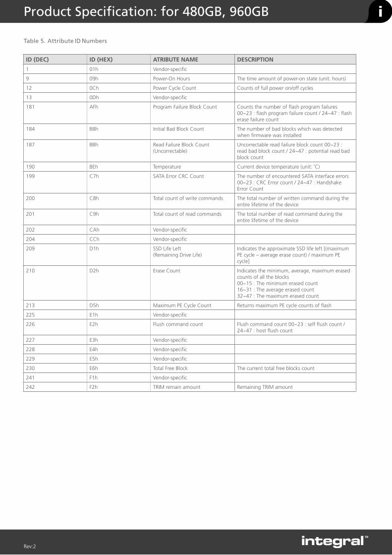
Table 5. Attribute ID Numbers
ID (DEC) ID (HEX) ATRIBUTE NAME DESCRIPTION
1 01h Vendor-specific
9 09h Power-On Hours The time amount of power-on state (unit: hours)
12 0Ch Power Cycle Count Counts of full power on/off cycles
13 0Dh Vendor-specific
181 AFh Program Failure Block Count Counts the number of flash program failures 00~23 : flash program failure count / 24~47 : flash erase failure count
184 B8h Initial Bad Block Count The number of bad blocks which was detected when firmware was installed
187 BBh Read Failure Block Count (Uncorrectable)
Uncorrectable read failure block count 00~23 : read bad block count / 24~47 : potential read bad block count
190 BEh Temperature Current device temperature (unit: ˚C)
199 C7h SATA Error CRC Count The number of encountered SATA interface errors 00~23 : CRC Error count / 24~47 : Handshake Error Count
200 C8h Total count of write commands The total number of written command during the entire lifetime of the device
201 C9h Total count of read commands The total number of read command during the entire lifetime of the device
202 CAh Vendor-specific
204 CCh Vendor-specific
209 D1h SSD Life Left(Remaining Drive Life)
Indicates the approximate SSD life left [(maximum PE cycle – average erase count) / maximum PE cycle]
210 D2h Erase Count Indicates the minimum, average, maximum erased counts of all the blocks00~15 : The minimum erased count16~31 : The average erased count32~47 : The maximum erased count
213 D5h Maximum PE Cycle Count Returns maximum PE cycle counts of flash
225 E1h Vendor-specific
226 E2h Flush command count Flush command count 00~23 : self flush count / 24~47 : host flush count
227 E3h Vendor-specific
228 E4h Vendor-specific
229 E5h Vendor-specific
230 E6h Total Free Block The current total free blocks count
241 F1h Vendor-specific
242 F2h TRIM remain amount Remaining TRIM amount

i iProduct Specification: for 480GB, 960GB
Rev:2
1.2.3 SMART SAVE ATTRIBUTE VALUES (SUBCOMMAND D3H)
This subcommand causes the device to immediately save any updated Attribute Values to the device’s Attribute Data sector regardless of the state of the Attribute Autosave feature.
1.2.4 SMART EXECUTE OFF-LINE IMMEDIATELY (SUBCOMMAND D4H)
This subcommand causes the device to start the off-line process for the requested mode and operation. The LBA Low register shall be set to specify the operation to be executed.
Table 6. SMART Execute Off-line Immediately
LBA LOW DESCRIPTION
00h Execute SMART off-line data collection routine immediately
01h Execute SMART Short self-test routine immediately in off-line mode
02h Execute SMART Extended self-test routine immediately in off-line mode
03h Reserved
04h Execute SMART Selective self-test routine immediately in off-line mode
40h Reserved
7Fh Abort off-line mode self-test routine
81h Execute SMART short self-test routine immediately in captive mode
82h Execute SMART Extended self-test routine immediately in captive mode
84h Execute SMART selective self-test routine immediately in captive mode
C0h Reserved
OFF-LINE MODE
The device executes command completion before executing the specified routine. During execution of the routine the device will not set BSY nor clear DRDY. If the device is in the process of performing its routine and is interrupted by a new command from the host, the device will abort or suspend its routine and service the host within two seconds after receipt of the new command. After servicing the interrupting command, the device will resume its routine automatically or not start its routine depending on the interrupting command.
CAPTIVE MODE
When executing self-test in captive mode, the device sets BSY to one and executes the specified self-test routine after receipt of the command. At the end of the routine, the device sets the execution result in the Self-test execution status byte (see Table 7-1: “Device Attribute Data Structure” on page 23) and ATA registers and then executes the command completion. See definitions below.
Status - Set ERR to one when the self-test has failed
Error - Set ABRT to one when the self-test has failed
LBA Low - Set to F4h when the self-test has failed
LBA High - Set to 2Ch when the self-test has failed
1.2.5 SMART READ LOG SECTOR (SUBCOMMAND D5H)
This command returns the specified log sector content to the host.LBA Low and Sector Count Registers shall be set to specify the log sector and sector number to be written.
Table 7. SMART Read Log Sector
LOG SECTOR ADDRESS
NO. SECTOR
CONTENT
00h 1 Log directory Read Only
01h 1 SMART error log Read Only
02h 51 Comprehensive SMART error log
Read Only
03h 37 Extended Comprehensive SMART error log
Read Only
06h 1 SMART self-test log Read Only
07h 1 Extended SMART self-test log
Read Only
09h 1 Selective self-test log Read and Write
10h 1 NCQ Error log Read only
11h 1 SATA Phy event counter log
Read only
80h-9Fh 32 Host vendor specific Read and Write
Table 8. SMART Log Directory
BYTE DESCRIPTION
0~1 SMART Logging Version (set to 01h)
2~3 Number of sectors in the log at log address 1
4~5 Number of sectors in the log at log address 2
…
510~511 Number of sectors in the log at log address 255
Table 9. Self-test log structure
BYTE DESCRIPTION
0~1 Data structure revision
n*24+2 Self-test number
n*24+3 Self-test execution status
n*24+4~n*24+5 Life timestamp
n*24+6 Self-test failure check point
n*24+7~n*24+10 LBA of first failure
n*24+11~n*24+25 Vendor specific
….. …..
506~507 Vendor specific
508 Self-test log pointer
509~510 Reserved
511 Data structure checksum
N is 0 through 20The data structure contains the descriptor of the Self-test that the device has performed. Each descriptor is 24 bytes long and the self-test data structure is capable to contain up to 21 descriptors. After 21 descriptors have been recorded, the oldest descriptor will be overwritten with the new descriptor. The self-test log pointer points to the most recent descriptor. When there is no descriptor, the value is 0. When there are descriptor(s), the value is 1 through 21.
i iProduct Specification: for 480GB, 960GB
Rev:2
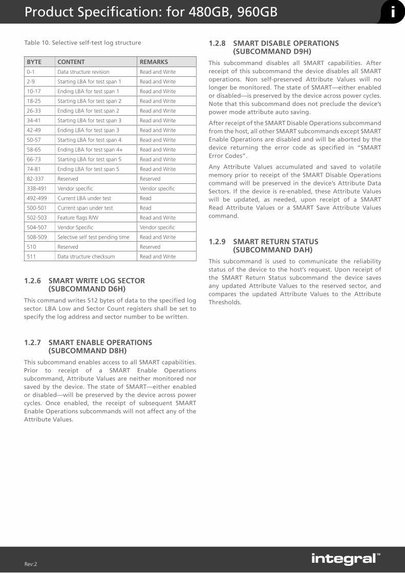
Table 10. Selective self-test log structure
BYTE CONTENT REMARKS
0-1 Data structure revision Read and Write
2-9 Starting LBA for test span 1 Read and Write
10-17 Ending LBA for test span 1 Read and Write
18-25 Starting LBA for test span 2 Read and Write
26-33 Ending LBA for test span 2 Read and Write
34-41 Starting LBA for test span 3 Read and Write
42-49 Ending LBA for test span 3 Read and Write
50-57 Starting LBA for test span 4 Read and Write
58-65 Ending LBA for test span 4+ Read and Write
66-73 Starting LBA for test span 5 Read and Write
74-81 Ending LBA for test span 5 Read and Write
82-337 Reserved Reserved
338-491 Vendor specific Vendor specific
492-499 Current LBA under test Read
500-501 Current span under test Read
502-503 Feature flags R/W Read and Write
504-507 Vendor Specific Vendor specific
508-509 Selective self test pending time Read and Write
510 Reserved Reserved
511 Data structure checksum Read and Write
1.2.6 SMART WRITE LOG SECTOR (SUBCOMMAND D6H)
This command writes 512 bytes of data to the specified log sector. LBA Low and Sector Count registers shall be set to specify the log address and sector number to be written.
1.2.7 SMART ENABLE OPERATIONS (SUBCOMMAND D8H)
This subcommand enables access to all SMART capabilities. Prior to receipt of a SMART Enable Operations subcommand, Attribute Values are neither monitored nor saved by the device. The state of SMART—either enabled or disabled—will be preserved by the device across power cycles. Once enabled, the receipt of subsequent SMART Enable Operations subcommands will not affect any of the Attribute Values.
1.2.8 SMART DISABLE OPERATIONS (SUBCOMMAND D9H)
This subcommand disables all SMART capabilities. After receipt of this subcommand the device disables all SMART operations. Non self-preserved Attribute Values will no longer be monitored. The state of SMART—either enabled or disabled—is preserved by the device across power cycles. Note that this subcommand does not preclude the device’s power mode attribute auto saving.
After receipt of the SMART Disable Operations subcommand from the host, all other SMART subcommands except SMART Enable Operations are disabled and will be aborted by the device returning the error code as specified in “SMART Error Codes”.
Any Attribute Values accumulated and saved to volatile memory prior to receipt of the SMART Disable Operations command will be preserved in the device’s Attribute Data Sectors. If the device is re-enabled, these Attribute Values will be updated, as needed, upon receipt of a SMART Read Attribute Values or a SMART Save Attribute Values command.
1.2.9 SMART RETURN STATUS (SUBCOMMAND DAH)
This subcommand is used to communicate the reliability status of the device to the host’s request. Upon receipt of the SMART Return Status subcommand the device saves any updated Attribute Values to the reserved sector, and compares the updated Attribute Values to the Attribute Thresholds.

i iProduct Specification: for 480GB, 960GB
Rev:2
WORDF=FIXEDV=VARIABLEX=BOTH
ATRIBUTE NAME DESCRIPTION
0 X 0040h General configuration bit-significant information
1 X 3FFFh Obsolete - Number of logical cylinders (16,383)
2 V C837h Specific configuration
3 X 0010h Obsolete - Number of logical heads (16)
4-5 X 0h Retired
6 X 003Fh Obsolete - Number of logical sectors per logical track (63)
7-8 V 0h Reserved for assignment by the CompactFlash* Association (CFA)
9 X 0h Retired
10-19 F varies Serial number (20 ASCII characters)
20-21 X 0h Retired
22 X 0000h Obsolete
23-26 F varies Firmware revision (8 ASCII characters)
27-46 F varies Model number
47 F 8001h Maximum number of sectors transferred per interrupt on multiple commands
48 F 4000h Trusted Computing Feature Set
49 F 2F00h Capabilities
50 F 4000h Capabilities
51-52 X 0h Obsolete
53 F 0007h Words 88 and 70:64 valid
54 X 3FFFh Obsolete - Number of logical cylinders (16,383)
55 X 0010h Obsolete - Number of logical heads (16)
56 X 003Fh Obsolete - Number of logical sectors per logical track (63)
57-58 X 0h Obsolete
59 F 0101 h Number of sectors transferred per interrupt on multiple commands
60-62 V varies Total number of user-addressable sector
63 X 0407h Multi-word DMA modes supported/selected
64 F 0003h PIO modes supported
65 F 0078h Minimum multiword DMA transfer cycle time per word
66 F 0078h Manufacturer’s recommended multiword DMA transfer cycle time
67 F 0078h Minimum PIO transfer cycle time without flow control
68 F 0078h Minimum PIO transfer cycle time with IORDY flow control
69 F 4020h Additional Supported
70 F 0000h Reserved
71-74 F 0h Reserved for IDENTIFY PACKET DEVICE command
75 F 001Fh Queue depth
76 F 050Eh Serial ATA capabilities
77 F 0006h Reserved for future Serial ATA definition
78 F 0044h Serial ATA features supported
79 V 0044h Serial ATA features enabled
80 F 01E0h Major version number
1.3 IDENTIFY DEVICE COMMAND DATA
Table 11. Returned Sector Data
NOTES:
F = Fixed. The content of the word is fixed and does not change. For removable media devices, these values may change when media is removed or changed.
V = Variable. The state of at least one bit in a word is variable and may change depending on the state of the device or the commands executed by the device.
X = F or V. The content of the word may be fixed or variable.

i iProduct Specification: for 480GB, 960GB
Rev:2
81 F 0000h Minor version number
82 F 346Bh Command set supported
83 F 7D01h Command sets supported
84 F 4122h Command set/feature supported extension
85 V 3469h Command set/feature enabled
86 V 3C01h Command set/feature enabled
87 V 4122h Command set/feature default
88 V 007Fh Ultra DMA Modes
89 F 0004h Time required for security erase unit completion
90 F 0004h Time required for enhanced security erase completion
91 V 0000h Current advanced power management value
92 V FFFEh Master Password Revision Code
93 X 0000h Hardware reset result: the contents of bits (12:0) of this word shall change only during the execution of a hardware reset
94 V 0000h Vendor’s recommended and actual acoustic management value
95 F 0000h Stream minimum request size
96 V 0000h Streaming transfer time - DMA
97 V 0000h Streaming access latency - DMA and PIO
98-99 F 0000h Streaming performance granularity
100-103 V Varies Maximum user LBA for 48-bit address feature set
104 V 0000h Streaming transfer time - PIO
105 V 0001h Maximum number of 512-byte blocks of LBA Range Entries per DATASET MANAGEMENT command
106 F 4000h Physical sector size / logical sector size
107 F 0000h Inter-seek delay for ISO-7779 acoustic testing in microseconds
108-111 F varies Unique ID
112-115 F 0h Reserved for world wide name extension to 128 bits
116 V 0000h Reserved for technical report
117-118 F 0h Words per logical sector
119 F 0000h Supported settings
120 F 0000h Command set/feature enabled/supported
121-126 F 0h Reserved
127 X 0000h Removable Media Status Notification feature set support
128 V 0001h Security status
129 V 0000h Vendor-specific
130-159 X 0h Vendor-specific
160 X 0000h CompactFlash Association (CFA) power mode 1
161-167 X 0h Reserved for assignment by the CFA
168 X 0003h Reserved for assignment by the CFA
169 X 0001h Data set management Trim attribute support
170-175 F 0h Reserved for assignment by the CFA
176-205 X 0h Current media serial number
206 X 0000h SCT Command Transport
207-208 F 0h Reserved
209 X 4000h Alignment of logical blocks within a physical block
WORDF=FIXEDV=VARIABLEX=BOTH
ATRIBUTE NAME DESCRIPTION
NOTES:
F = Fixed. The content of the word is fixed and does not change. For removable media devices, these values may change when media is removed or changed.
V = Variable. The state of at least one bit in a word is variable and may change depending on the state of the device or the commands executed by the device.
X = F or V. The content of the word may be fixed or variable.

i iProduct Specification: for 480GB, 960GB
Rev:2
210-211 V 0h Write-Read-Verify Sector Count Mode 3 (DWord)
212-213 F 0h Write-Read-Verify Sector Count Mode 2 (DWord)
214 X 0000h NV Cache Capabilities
215-216 V 0h NV Cache Size in Logical Blocks (DWord)
217 F 0001h Nominal media rotation rate
218 V 0000h Reserved
219 F 0000h NV Cache Options
220 V 0000h Write-Read-Verify feature set
221 X 0000h Reserved
222 F 103Fh Transport major version number
223 F 0000h Transport minor version number
224-229 F 0h Reserved
230-233 X 0h Extended Number of User Addressable Sectors (QWord)
234 F 0000h Minimum number of 512-byte data blocks per DOWNLOAD MICROCODE command for mode 03h
235 F 0000h Maximum number of 512-byte data blocks per DOWNLOAD MICROCODE command for mode 03h
236-254 X 0h Reserved
255 V varies Integrity word
WORDF=FIXEDV=VARIABLEX=BOTH
ATRIBUTE NAME DESCRIPTION
NOTES:
F = Fixed. The content of the word is fixed and does not change. For removable media devices, these values may change when media is removed or changed.
V = Variable. The state of at least one bit in a word is variable and may change depending on the state of the device or the commands executed by the device.
X = F or V. The content of the word may be fixed or variable.

i iProduct Specification
Rev:1
PRODUCT OVERVIEW
The SVR-PRO 100 SRI SSD range is designed for Read intensive applications, offers up to a massive 8TB of data storage and features consistently low latency with a superior level of read and write IOPS, together with power-loss protection.
Delivers solid I/O cost-to-performance benefits for applications that demand low latency read speeds for server and storage environments for Serial Advanced Technology Attachment (SATA)-based systems in capacities of 4TB and 8TB.
Uses a single-chip controller with a SATA interface on the system side and 8-channels of HLNAND Flash internally. The industry-standard 2.5-inch form factor enables interchangeability with existing hard disk drives (HDDs) and native SATA HDD drop-in replacement with the enhanced performance, reliability, ruggedness, and power savings offered by an SSD.
SVR-PRO 100 has the capacity you require for storage-hungry SATA based systems.
BENEFITS
• High capacity SSDs for big data storage
• Designed for read intensive applications
• Reduced latencies
• Lower Power Consumption
• Non-volatile Flash Memory for outstanding data retention - Less likely to fail than HDD
• Shock resistance - No moving parts enable the product to be used in tougher conditions
• Silent operation - Noiseless and low heat dissipation
• Much less heat generated than conventional HDD
FEATURES
• 2.5” form factor with SATA III 6Gbps interface (backwards compatible with SATA 3Gbps and SATA 1.5Gbps)
• Sequential Read up to 551MB/s and Write up 517MB/s
• Random Read IOPS up to 52K, Random Write up to 78K
• TBW – Up to 2000 (8TB model)
• Supports S.M.A.R.T. - Self-Monitoring, Analysis and Reporting Technology
• Features an internal temperature sensor with an accuracy of +/-2°C over a range of -40°C to +125°C which can be monitored using a SMART attribute BEh
• The SSD hardware is built with a number of capacitors that ensure that the data in the write cache of the SSD is protected against corruption if a power loss was to occur, enabling the SSD to complete the last write command to the NAND flash.
• CE and FCC compliant
• 5 Year Warranty or TBW
Integral SVR-PRO 100 SRI 2.5” SATA 6Gbps SSD
INTRODUCTIONThe Integral SVR-PRO 100 SRI SATA III 6Gbps 2.5” SSD offers massive 4TB and 8TB of storage and delivers all of the advantages of flash memory technology for ultimate performance and reliability. The best big data SSD solution for server and desktop computing environments. Ideal for read intensive and performance hungry applications; including Video on Demand, streaming, Web server, file server and operating system boot.
8TB
4TB
15mm
7mm

i iProduct Specification: for 4TB, 8TB
Rev:1
CAPACITY PART CODE BARCODE (EAN)
4TB INSSD4TS625SVR100SRI 5055288435056
8TB INSSD8TS625SVR100SRI 5055288435063
Notes:
1. Actual performance may vary and depends on use conditions, host and environment
2. 4KB transfers used for Read/Write latency values.
3. Typical I/O performance numbers as measured fresh-out-of-the-box (FOB) using IOmeter with a queue depth 32 and write cache enabled.
4. The product achieves a mean time between failure (MTBF) based on population statistics not relevant to individual units.
5. Based on full sustained 128K random write workload
6. Operating temperature is the drive case temperature as measured by the SMART temperature attribute
7. Mean Time Between Failures is estimated based on JEDEC-218/219 standard methodology.
8. TBW (Terabytes Written). TBW is a measurement of SSDs expected lifespan, which represents the amount of data written to the device. This is only an estimate and can differ based in user usage behaviour, platform and estimates provided by the flash vendor
9. Power Consumption may differ according to flash configuration and platform
HLNAND™ is a trademark of Novachips Co., Ltd
All Specifications are subject to change without notice
1GB = 1,000,000,000 Bytes, 1TB = 1,000,000,000,000 Bytes; 1 sector = 512 Bytes.
The total usable capacity of the SSD may be less than the total physical capacity because a small portion of the capacity is used for NAND flash management and maintenance purposes.
CAPACITIES & INTERFACE
Capacities available 4TB and 8TB
Form Factor 2.5 Inch
InterfaceSATA III 6Gbps (also Compatible with SATA II 3Gbps and SATA 1.5Gbps)
Controller Novachips
NAND HLNAND MLC
DIMENSIONS
Length mm 100.45
Width mm 69.85
Height mm 4TB: 7mm, 8TB: 15mm
Weight 4TB = 120g, 8TB 200g
Sequential Performance up to
4TB: Read:551MB/s Write: 517MB/s8TB: Read:551MB/s Write: 517MB/s
Random Performance 4TB: Read 52K IOPS, Write 78K IOPS8TB: Read 49K IOPS, Write 77K IOPS
Typical Latency Read: 65us, Write: 40us
Operating Temp 0 to 70°C
Humidity 5% to 95%, non-condensing
Supply Voltage 4.5V minimum – 5.5V maximum
Power Consumptionmaximum (Watt)
4TB Sequential Read: 5.9W / Write 8.45WRandom 4K: Read: 5W / Write 8.40WIdle: 2.78W8TB Sequential: Read: 8.94W / Write: 8.45WRandom 4K: Read: 5.44W / Write 9.40WIdle: 3.10W
POWER CONSUMPTION
Average (Watt)
4TB Sequential: Read: 3.63W / Write: 5.5WRandom 4K: Read: 3.33W / Write 4.85WIdle: 2.17W8TB Sequential: Read: 4.59W / Write: 6.09WRandom 4K: Read: 4.03W / Write 5.17WIdle: 2.73W
Shock (operating and non operating
1000G, duration 0.5ms
VibrationOperating 2.17 Grms (5-700Hz, Non-Operating 3.13 Grms (5-800Hz)
Supports SMART Yes
MTBF 1.5 Million Hours
TBW 4TB: 1000 TBW, 8TB 2000 TBW
WARRANTY 5 YEARS or TBW
Compliancy CE, FCC, RoHS
Bulk Weight 4TB = 120g, 8TB 200g
Packaged Weight 4TB = 178g 8TB = 258g
Packaged Dimensions (mm) L = 120 W = 163 H = 31

i iProduct Specification: for 4TB, 8TB
Rev:1
4TB diagram
(2.5” 7mm z-height)
8TB diagram
2.5” 15mm z-height

i iProduct Specification: for 4TB, 8TB
Rev:1
COMMAND NAME COMMAND CODE (HEX)
CHECK POWER MODE E5h or 98h
DEVICE RESET 08h
DEVICE CONFIGURATION
DEVICE CONFIGURATION FREEZE LOCK B1h/C1h
DEVICE CONFIGURATION IDENTIFY B1h/C2h
DEVICE CONFIGURATION RESTORE B1h/C0h
DEVICE CONFIGURATION SET B1h/C3h
DOWNLOAD MICROCODE 92h
DATA SET MANAGEMENT 06h
EXECUTE DEVICE DIAGNOSTIC 90h
FLUSH CACHE E7h
FLUSH CACHE EXT EAh
IDENTIFY DEVICE ECh
IDLE E3h or 97h
IDLE IMMEDIATE E1h or 95h
INITIALIZE DEVICE PARAMETERS 91h
READ BUFFER E4h
READ DMA C8h
READ DMA EXT 25h
READ FPDMA QUEUED 60h
READ LOG EXT 2Fh
READ MULTIPLE C4h
READ MULTIPLE EXT 29h
READ NATIVE MAX ADDRESS F8h
READ NATIVE MAX ADDRESS EXT 27h
READ SECTOR(S) 20h
READ SECTOR(S) EXT 24h
READ VERIFY SECTOR(S) 40h
READ VERIFY SECTOR(S) EXT 42h
SECURITY DISABLE PASSWORD F6h
SECURITY ERASE PREPARE F3h
SECURITY ERASE UNIT F4h
SECURITY FREEZE LOCK F5h
SECURITY SET PASSWORD F1h
SECURITY UNLOCK F2h
SEEK 70h
SET FEATURES
Enable write cache EFh/02h
Disable write cache EFh/82h
Set transfer mode EFh/03h
Enable Power-Up In Standby Efh/06h
Disable Power-Up In Standby Efh/86h
Enable DMA Setup FIS Auto-Activate optimization
Efh/10h/02h
Disable DMA Setup FIS Auto-Activate optimization
Efh/90h/02h
Enable Device-initiated interface power state transitions
Efh/10h/03h
Disable Device-initiated interface power state transitions
Efh/90h/03h
SET MAX
SET MAX ADDRESS F9h/na
SET MAX FREEZE LOCK F9h/04h
SET MAX LOCK F9h/02h
SET MAX SET PASSWORD F9h/01h
SET MAX UNLOCK F9h/03h
SET MAX ADDRESS EXT 37h
SET MULTIPLE MODE C6h
SLEEP E6h or 99h
SMART
SMART DISABLE OPERATIONS B0h/D9h
SMART ENABLE OPERATIONS B0h/D8h
SMART ENABLE/DISABLE ATTRIBUTE AUTOSAVE
B0h/D2h
SMART EXECUTE OFF-LINE IMMIDIATE B0h/D4h
SMART READ ATTRIBUTE THRESHOLDS B0h/D1h
SMART READ DATA B0h/D0h
SMART READ LOG B0h/D5h
SMART RETURN STATUS B0h/DAh
SMART SAVE ATTRIBUTE VALUES B0h/D3h
SMART WRITE LOG B0h/D6h
STANDBY E2h or 96h
STANDBY IMMEDIATE E0h or 94h
SOFT RESET FFh
WRITE BUFFER E8h
WRITE DMA CAh
WRITE DMA EXT 35h
WRITE FPDMA QUEUED 61h
WRITE LOG EXT 3Fh
WRITE MULTIPLE C5h
WRITE MULTIPLE EXT 39h
WRITE SECTOR(S) 30h
WRITE SECTOR(S) EXT 34h
1.1 SUPPORTED COMMAND SETS
Table 1. Supported Command Sets

i iProduct Specification: for 4TB, 8TB
Rev:1
BYTE DESCRIPTION
0~1 Data structure revision number (Vendor Specific)
2~361 1st - 30th Individual attribute data (Vendor Specific)
362 Off-line data collection status
363 Self-test execution status
364~365 Total time in seconds to complete off-line data collection activity
366 Vendor Specific
367 Off-line data collection capability
368-369 SMART capability
370 Error logging capability7-1 Reserved0 1=Device error logging supported
371 Self-test failure check point (Vendor Specific)
372 Short self-test routine recommended polling time(in minutes)
373 Extended self-test routine recommended polling time(in minutes)
374-510 Reserved
511 Data structure checksum
1.2 SMART
1.2.1 SMART SUBCOMMAND SETS
In order to select a subcommand the host must write the subcommand code to the device’s Features Register before issuing the SMART Function Set command. The subcommands are listed below.
Table 2. SMART Subcommand Sets
Table 4. Individual Attribute Data Structure
Table 5. Attribute ID Numbers
1.2.2 SMART READ DATA (SUBCOMMAND D0H)
This subcommand returns the device’s Attribute Values to the host. The Attribute Values consist of 512bytes.
Table 3. Device Attribute Data Structure
COMMAND COMMAND CODE (HEX)
SMART READ DATA D0h
SMART ENABLE/DISABLE ATTRIBUTE AUTOSAVE
D2h
SMART EXECUTE OFF-LINE IMMIDIATE D4h
SMART READ LOG D5h
SMART WRITE LOG D6h
SMART ENABLE OPERATIONS D8h
SMART DISABLE OPERATIONS D9h
SMART RETURN STATUS DAh
BYTE DESCRIPTION
0 Attribute ID Number
1~2 Flags
3 Current Value
4 Worst Value
5~10Attribute Value (FFFF FFFF FFFFh)
11 Reserved
i iProduct Specification: for 4TB, 8TB
Rev:1
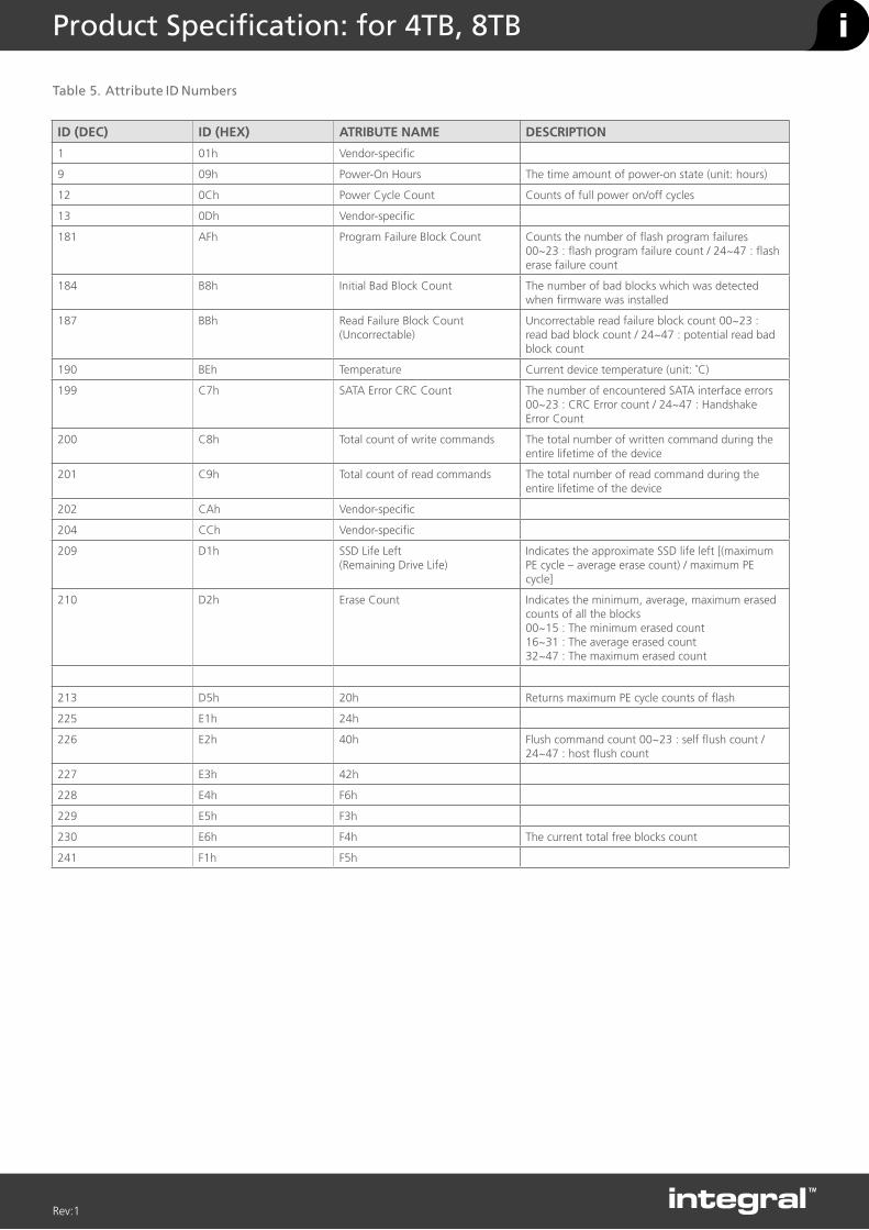
Table 5. Attribute ID Numbers
ID (DEC) ID (HEX) ATRIBUTE NAME DESCRIPTION
1 01h Vendor-specific
9 09h Power-On Hours The time amount of power-on state (unit: hours)
12 0Ch Power Cycle Count Counts of full power on/off cycles
13 0Dh Vendor-specific
181 AFh Program Failure Block Count Counts the number of flash program failures 00~23 : flash program failure count / 24~47 : flash erase failure count
184 B8h Initial Bad Block Count The number of bad blocks which was detected when firmware was installed
187 BBh Read Failure Block Count (Uncorrectable)
Uncorrectable read failure block count 00~23 : read bad block count / 24~47 : potential read bad block count
190 BEh Temperature Current device temperature (unit: ˚C)
199 C7h SATA Error CRC Count The number of encountered SATA interface errors 00~23 : CRC Error count / 24~47 : Handshake Error Count
200 C8h Total count of write commands The total number of written command during the entire lifetime of the device
201 C9h Total count of read commands The total number of read command during the entire lifetime of the device
202 CAh Vendor-specific
204 CCh Vendor-specific
209 D1h SSD Life Left(Remaining Drive Life)
Indicates the approximate SSD life left [(maximum PE cycle – average erase count) / maximum PE cycle]
210 D2h Erase Count Indicates the minimum, average, maximum erased counts of all the blocks00~15 : The minimum erased count16~31 : The average erased count32~47 : The maximum erased count
213 D5h 20h Returns maximum PE cycle counts of flash
225 E1h 24h
226 E2h 40h Flush command count 00~23 : self flush count / 24~47 : host flush count
227 E3h 42h
228 E4h F6h
229 E5h F3h
230 E6h F4h The current total free blocks count
241 F1h F5h

i iProduct Specification: for 4TB, 8TB
Rev:1
1.2.3 SMART EXECUTE OFF-LINE IMMEDIATELY (SUBCOMMAND D4H)
This subcommand causes the device to start the off-line process for the requested mode and operation. The LBA Low register shall be set to specify the operation to be executed.
Table 6. SMART Execute Off-line Immediately
LBA LOW DESCRIPTION
00h Execute SMART off-line data collection routine immediately
01h Execute SMART Short self-test routine immediately in off-line mode
02h Execute SMART Extended self-test routine immediately in off-line mode
03h Reserved
04h Execute SMART Selective self-test routine immediately in off-line mode
40h Reserved
7Fh Abort off-line mode self-test routine
81h Execute SMART short self-test routine immediately in captive mode
82h Execute SMART Extended self-test routine immediately in captive mode
84h Execute SMART selective self-test routine immediately in captive mode
C0h Reserved
OFF-LINE MODE
The device executes command completion before executing the specified routine. During execution of the routine the device will not set BSY nor clear DRDY. If the device is in the process of performing its routine and is interrupted by a new command from the host, the device will abort or suspend its routine and service the host within two seconds after receipt of the new command. After servicing the interrupting command, the device will resume its routine automatically or not start its routine depending on the interrupting command.
CAPTIVE MODE
When executing self-test in captive mode, the device sets BSY to one and executes the specified self-test routine after receipt of the command. At the end of the routine, the device sets the execution result in the Self-test execution status byte (see Table 7-1: “Device Attribute Data Structure” on page 23) and ATA registers and then executes the command completion. See definitions below.
Status - Set ERR to one when the self-test has failed
Error - Set ABRT to one when the self-test has failed
LBA Low - Set to F4h when the self-test has failed
LBA High - Set to 2Ch when the self-test has failed
1.2.4 SMART READ LOG SECTOR (SUBCOMMAND D5H)
This command returns the specified log sector content to the host. LBA Low and Sector Count Registers shall be set to specify the log sector and sector number to be written.
Table 7. SMART Read Log Sector
LOG SECTOR ADDRESS
NO. SECTOR
CONTENT
00h 1 Log directory Read Only
01h 1 SMART error log Read Only
02h 51 Comprehensive SMART error log
Read Only
03h 37 Extended Comprehensive SMART error log
Read Only
06h 1 SMART self-test log Read Only
07h 1 Extended SMART self-test log
Read Only
09h 1 Selective self-test log Read and Write
10h 1 NCQ Error log Read only
11h 1 SATA Phy event counter log
Read only
80h-9Fh 32 Host vendor specific Read and Write
A0h 1 Reserved Vendor Specific
Table 8. SMART Log DirectoryTable
BYTE DESCRIPTION
0~1 SMART Logging Version (set to 01h)
2~3 Number of sectors in the log at log address 1
4~5 Number of sectors in the log at log address 2
…
510~511 Number of sectors in the log at log address 255
Table 9. Self-test log structureTable 5.
BYTE DESCRIPTION
0~1 Data structure revision
n*24+2 Self-test number
n*24+3 Self-test execution status
n*24+4~n*24+5 Life timestamp
n*24+6 Self-test failure check point
n*24+7~n*24+10 LBA of first failure
n*24+11~n*24+25 Vendor specific
….. …..
506~507 Vendor specific
508 Self-test log pointer
509~510 Reserved
511 Data structure checksum
N is 0 through 20The data structure contains the descriptor of the Self-test that the device has performed. Each descriptor is 24 bytes long and the self-test data structure is capable to contain up to 21 descriptors. After 21 descriptors have been recorded, the oldest descriptor will be overwritten with the new descriptor. The self-test log pointer points to the most recent descriptor. When there is no descriptor, the value is 0. When there are descriptor(s), the value is 1 through 21.

i iProduct Specification: for 4TB, 8TB
Rev:1
Table 10. Selective self-test log structure
BYTE CONTENT REMARKS
0-1 Data structure revision Read and Write
2-9 Starting LBA for test span 1 Read and Write
10-17 Ending LBA for test span 1 Read and Write
18-25 Starting LBA for test span 2 Read and Write
26-33 Ending LBA for test span 2 Read and Write
34-41 Starting LBA for test span 3 Read and Write
42-49 Ending LBA for test span 3 Read and Write
50-57 Starting LBA for test span 4 Read and Write
58-65 Ending LBA for test span 4+ Read and Write
66-73 Starting LBA for test span 5 Read and Write
74-81 Ending LBA for test span 5 Read and Write
82-337 Reserved Reserved
338-491 Vendor specific Vendor specific
492-499 Current LBA under test Read
500-501 Current span under test Read
502-503 Feature flags R/W Read and Write
504-507 Vendor Specific Vendor specific
508-509 Selective self test pending time Read and Write
510 Reserved Reserved
511 Data structure checksum Read and Write
1.2.5 SMART WRITE LOG SECTOR (SUBCOMMAND D6H)
This command writes 512 bytes of data to the specified log sector. LBA Low and Sector Count registers shall be set to specify the log address and sector number to be written.
1.2.6 SMART ENABLE OPERATIONS (SUBCOMMAND D8H)
This subcommand enables access to all SMART capabilities. Prior to receipt of a SMART Enable Operations subcommand, Attribute Values are neither monitored nor saved by the device. The state of SMART—either enabled or disabled—will be preserved by the device across power cycles. Once enabled, the receipt of subsequent SMART Enable Operations subcommands will not affect any of the Attribute Values.
1.2.7 SMART DISABLE OPERATIONS (SUBCOMMAND D9H)
This subcommand disables all SMART capabilities. After receipt of this subcommand the device disables all SMART operations. Non self-preserved Attribute Values will no longer be monitored. The state of SMART - either enabled or disabled - is preserved by the device across power cycles. Note that this subcommand does not preclude the device’s power mode attribute auto saving.
After receipt of the SMART Disable Operations subcommand from the host, all other SMART subcommands except SMART Enable Operations are disabled and will be aborted by the device returning the error code as specified in “SMART Error Codes”.
Any Attribute Values accumulated and saved to volatile memory prior to receipt of the SMART Disable Operations command will be preserved in the device’s Attribute Data Sectors. If the device is re-enabled, these Attribute Values will be updated, as needed, upon receipt of a SMART Read Attribute Values or a SMART Save Attribute Values command.
1.2.8 SMART RETURN STATUS (SUBCOMMAND DAH)
This subcommand is used to communicate the reliability status of the device to the host’s request. Upon receipt of the SMART Return Status subcommand the device saves any updated Attribute Values to the reserved sector, and compares the updated Attribute Values to the Attribute Thresholds.

i iProduct Specification: for 4TB, 8TB
Rev:1
WORDF=FIXEDV=VARIABLEX=BOTH
ATRIBUTE NAME DESCRIPTION
0 X 0040h General configuration bit-significant information
1 X 3FFFh Obsolete - Number of logical cylinders (16,383)
2 V C837h Specific configuration
3 X 0010h Obsolete - Number of logical heads (16)
4-5 X 0h Retired
6 X 003Fh Obsolete - Number of logical sectors per logical track (63)
7-8 V 0h Reserved for assignment by the CompactFlash* Association (CFA)
9 X 0h Retired
10-19 F varies Serial number (20 ASCII characters)
20-21 X 0h Retired
22 X 0000h Obsolete
23-26 F varies Firmware revision (8 ASCII characters)
27-46 F varies Model number
47 F 8001h Maximum number of sectors transferred per interrupt on multiple commands
48 F 4000h Trusted Computing Feature Set
49 F 2F00h Capabilities
50 F 4000h Capabilities
51-52 X 0h Obsolete
53 F 0007h Words 88 and 70:64 valid
54 X 3FFFh Obsolete - Number of logical cylinders (16,383)
55 X 0010h Obsolete - Number of logical heads (16)
56 X 003Fh Obsolete - Number of logical sectors per logical track (63)
57-58 X 0h Obsolete
59 F 0101 h Number of sectors transferred per interrupt on multiple commands
60-62 V varies Total number of user-addressable sector
63 X 0407h Multi-word DMA modes supported/selected
64 F 0003h PIO modes supported
65 F 0078h Minimum multiword DMA transfer cycle time per word
66 F 0078h Manufacturer’s recommended multiword DMA transfer cycle time
67 F 0078h Minimum PIO transfer cycle time without flow control
68 F 0078h Minimum PIO transfer cycle time with IORDY flow control
69 F 4020h Additional Supported
70 F 0000h Reserved
71-74 F 0h Reserved for IDENTIFY PACKET DEVICE command
75 F 001Fh Queue depth
76 F 050Eh Serial ATA capabilities
77 F 0006h Reserved for future Serial ATA definition
78 F 0044h Serial ATA features supported
79 V 0044h Serial ATA features enabled
80 F 01E0h Major version number
1.3 IDENTIFY DEVICE COMMAND DATA
Table 11. Returned Sector Data
NOTES:
F = Fixed. The content of the word is fixed and does not change. For removable media devices, these values may change when media is removed or changed.
V = Variable. The state of at least one bit in a word is variable and may change depending on the state of the device or the commands executed by the device.
X = F or V. The content of the word may be fixed or variable.

i iProduct Specification: for 4TB, 8TB
Rev:1
81 F 0000h Minor version number
82 F 346Bh Command set supported
83 F 7D01h Command sets supported
84 F 4122h Command set/feature supported extension
85 V 3469h Command set/feature enabled
86 V 3C01h Command set/feature enabled
87 V 4122h Command set/feature default
88 V 007Fh Ultra DMA Modes
89 F 0004h Time required for security erase unit completion
90 F 0004h Time required for enhanced security erase completion
91 V 0000h Current advanced power management value
92 V FFFEh Master Password Revision Code
93 X 0000h Hardware reset result: the contents of bits (12:0) of this word shall change only during the execution of a hardware reset
94 V 0000h Vendor’s recommended and actual acoustic management value
95 F 0000h Stream minimum request size
96 V 0000h Streaming transfer time - DMA
97 V 0000h Streaming access latency - DMA and PIO
98-99 F 0000h Streaming performance granularity
100-103 V Varies Maximum user LBA for 48-bit address feature set
104 V 0000h Streaming transfer time - PIO
105 V 0001h Maximum number of 512-byte blocks of LBA Range Entries per DATASET MANAGEMENT command
106 F 4000h Physical sector size / logical sector size
107 F 0000h Inter-seek delay for ISO-7779 acoustic testing in microseconds
108-111 F varies Unique ID
112-115 F 0h Reserved for world wide name extension to 128 bits
116 V 0000h Reserved for technical report
117-118 F 0h Words per logical sector
119 F 0000h Supported settings
120 F 0000h Command set/feature enabled/supported
121-126 F 0h Reserved
127 X 0000h Removable Media Status Notification feature set support
128 V 0001h Security status
129 V 0000h Vendor-specific
130-159 X 0h Vendor-specific
160 X 0000h CompactFlash Association (CFA) power mode 1
161-167 X 0h Reserved for assignment by the CFA
168 X 0003h Reserved for assignment by the CFA
169 X 0001h Data set management Trim attribute support
170-175 F 0h Reserved for assignment by the CFA
176-205 X 0h Current media serial number
206 X 0000h SCT Command Transport
207-208 F 0h Reserved
209 X 4000h Alignment of logical blocks within a physical block
WORDF=FIXEDV=VARIABLEX=BOTH
ATRIBUTE NAME DESCRIPTION
NOTES:
F = Fixed. The content of the word is fixed and does not change. For removable media devices, these values may change when media is removed or changed.
V = Variable. The state of at least one bit in a word is variable and may change depending on the state of the device or the commands executed by the device.
X = F or V. The content of the word may be fixed or variable.

i iProduct Specification: for 4TB, 8TB
Rev:1
210-211 V 0h Write-Read-Verify Sector Count Mode 3 (DWord)
212-213 F 0h Write-Read-Verify Sector Count Mode 2 (DWord)
214 X 0000h NV Cache Capabilities
215-216 V 0h NV Cache Size in Logical Blocks (DWord)
217 F 0001h Nominal media rotation rate
218 V 0000h Reserved
219 F 0000h NV Cache Options
220 V 0000h Write-Read-Verify feature set
221 X 0000h Reserved
222 F 103Fh Transport major version number
223 F 0000h Transport minor version number
224-229 F 0h Reserved
230-233 X 0h Extended Number of User Addressable Sectors (QWord)
234 F 0000h Minimum number of 512-byte data blocks per DOWNLOAD MICROCODE command for mode 03h
235 F 0000h Maximum number of 512-byte data blocks per DOWNLOAD MICROCODE command for mode 03h
236-254 X 0h Reserved
255 V varies Integrity word
WORDF=FIXEDV=VARIABLEX=BOTH
ATRIBUTE NAME DESCRIPTION
NOTES:
F = Fixed. The content of the word is fixed and does not change. For removable media devices, these values may change when media is removed or changed.
V = Variable. The state of at least one bit in a word is variable and may change depending on the state of the device or the commands executed by the device.
X = F or V. The content of the word may be fixed or variable.