InTech-Simulations of Composite Reinforcement Forming
29
20 Simulations of Woven Composite Reinforcement Forming Philippe Boisse Université de Lyon, LaMCoS, INSA-Lyon, 69621 F r anc e 1. Introduction Complex preforms can be obtained by forming an initially flat textile composite reinforcement. Then the resin is injected on the preform in LCM processes (Liquid Composite Moulding)(Advani, 1994, Rudd & Long, 1997, Parnas, 2000). These processes and especially the RTM process (Resin Transfert Moulding) can be used to manufacture highly loaded composite part for aeronautical application (e.g. the helicopter frame and the motor blade presented in figures 1 and 2). Numerical optimization of products and production processes becomes increasingly important in the design phase of composite structures. Numerical simulations of the composite forming processes are an essential part of these optimization tools. They permit to determine the conditions of the feasibility of a process without defect (wrinkling, fracture of yarns, porosities…) but above all, they give the fibre orientations after shaping. This is mainly important because redistribution of the fibres is inevitable when double curved products are considered. The fibre orientations strongly influence the mechanical behaviour of the final part and the permeability of the reinforcement and thus the injection of the resin in the case of a liquid moulding process The first method used for analysing composite forming processes, and especially draping in woven composite reinforcements, is “kinematic models”. The fibre distribution of a woven cloth is predicted on a given geometry based on a pin jointed net assumption (fishnet algorithm). The yarns of the fabric are assumed to be inextensible and the rotation between warp and weft yarns is free. The woven reinforcement is placed progressively from initial lines. Several packages are commercially available. This method is briefly described in section 2. It is fairly efficient for hand draping in classical prepreg fabrics, but the models do not account for load boundary conditions, for possible sliding of the fabric in relation to the tools, and for the mechanical behaviour of the woven reinforceme nt For a physical analysis of a composite forming process, the complete model must include all the equations for the mechanics, especially equilibrium, constitutive equations, and boundary conditions. These equations must be solved numerically, with some approximations. Finite Element Analysis of the composite forming process includes the tools modelling, the contact and friction between the different parts, and above all, the mechanical behaviour of the composite during forming. If these models can be numerically costly, problems of computation time are steadily reduced through improved processing www.intechopen.com
-
Upload
bxlmichael8837 -
Category
Documents
-
view
220 -
download
0
Transcript of InTech-Simulations of Composite Reinforcement Forming
7/28/2019 InTech-Simulations of Composite Reinforcement Forming
http://slidepdf.com/reader/full/intech-simulations-of-composite-reinforcement-forming 1/29
20
Simulations of Woven CompositeReinforcement Forming
Philippe BoisseUniversité de Lyon, LaMCoS, INSA-Lyon, 69621
France
1. Introduction
Complex preforms can be obtained by forming an initially flat textile compositereinforcement. Then the resin is injected on the preform in LCM processes (LiquidComposite Moulding)(Advani, 1994, Rudd & Long, 1997, Parnas, 2000). These processes and
especially the RTM process (Resin Transfert Moulding) can be used to manufacture highly
loaded composite part for aeronautical application (e.g. the helicopter frame and the motorblade presented in figures 1 and 2).
Numerical optimization of products and production processes becomes increasingly
important in the design phase of composite structures. Numerical simulations of the
composite forming processes are an essential part of these optimization tools. They permitto determine the conditions of the feasibility of a process without defect (wrinkling, fracture
of yarns, porosities…) but above all, they give the fibre orientations after shaping. This ismainly important because redistribution of the fibres is inevitable when double curved
products are considered. The fibre orientations strongly influence the mechanical behaviour
of the final part and the permeability of the reinforcement and thus the injection of the resin
in the case of a liquid moulding process
The first method used for analysing composite forming processes, and especially draping inwoven composite reinforcements, is “kinematic models”. The fibre distribution of a woven
cloth is predicted on a given geometry based on a pin jointed net assumption (fishnetalgorithm). The yarns of the fabric are assumed to be inextensible and the rotation between
warp and weft yarns is free. The woven reinforcement is placed progressively from initial
lines. Several packages are commercially available. This method is briefly described in
section 2. It is fairly efficient for hand draping in classical prepreg fabrics, but the models donot account for load boundary conditions, for possible sliding of the fabric in relation to thetools, and for the mechanical behaviour of the woven reinforcement
For a physical analysis of a composite forming process, the complete model must include allthe equations for the mechanics, especially equilibrium, constitutive equations, andboundary conditions. These equations must be solved numerically, with someapproximations. Finite Element Analysis of the composite forming process includes thetools modelling, the contact and friction between the different parts, and above all, themechanical behaviour of the composite during forming. If these models can be numericallycostly, problems of computation time are steadily reduced through improved processing
www.intechopen.com

7/28/2019 InTech-Simulations of Composite Reinforcement Forming
http://slidepdf.com/reader/full/intech-simulations-of-composite-reinforcement-forming 2/29
Woven Fabric Engineerings388
capabilities. The main problem for the FE approach therefore lies in the requirement foraccurate models of all the significant aspects of the forming process.
Fig. 1. Preform/RTM parts in NH90 (Dumont et al. 2008) (Courtesy of Eurocopter, EADSGroup)
www.intechopen.com

7/28/2019 InTech-Simulations of Composite Reinforcement Forming
http://slidepdf.com/reader/full/intech-simulations-of-composite-reinforcement-forming 3/29
Simulations of Woven Composite Reinforcement Forming 389
Fig. 2. Plane motor blade (Courtesy of Snecma, Groupe Safran) (De Luycker et al. 2009)
The mechanical behaviour of fabrics is complex due to the intricate interactions of the yarnsand fibres. It is a multi-scale problem. The macroscopic behaviour is very dependent on theinteractions of yarns at the meso-scale (scale of the woven unit cell) and at the micro-scale(level of the fibres constituting yarns). Despite the many works in the field, there is nowidely accepted model that accurately describes all the main aspects of a composite wovenreinforcement mechanical behaviour. The approaches to model the forming of textilecomposite reinforcements belong to two main families that are related to the scale at whichthe analysis is made. The textile reinforcement is a set of yarns (or fibres). The analysis of theforming can be made considering and modelling each of these yarns (or fibres) and theirinteractions (contact with friction). In this case the approach is called discrete or mesoscopic.Of course the number of yarns is high and the interactions are complex. On the opposite, the
continuous approaches consider a continuous medium juxtaposed with the fabric and themechanical behaviour of which is equivalent to those of the textile reinforcement. Thismechanical behaviour is complex because it concerns large strains and strong anisotropy.Furthermore, it strongly changes during the forming.The present chapter aims to present continuous and discrete approaches for compositereinforcements forming simulations. First two continuous approaches are described within amembrane assumption. The first one is based on a hyperelastic model and the second on ahypoelastic one. Then simulations of woven fabric forming based on a discrete approach arepresented. Finally a semi-discrete approach which can be seen as an intermediate methodbetween continuous and discrete ones is presented. This approach is extended to 3D interlockforming simulations. The advantages and drawback of the different approaches are discussed.
www.intechopen.com

7/28/2019 InTech-Simulations of Composite Reinforcement Forming
http://slidepdf.com/reader/full/intech-simulations-of-composite-reinforcement-forming 4/29
Woven Fabric Engineerings390
Fig. 3. Fishnet algorithm: Calculation of the position of point C knowing those of A and B
2. Kinematic models
“Kinematic models” also called fishnet algorithms are commonly used in industry foranalysing composite forming processes, and especially draping in woven compositereinforcements (Mark, 1956, Van Der Ween, 1991, Long et al, 1994, Borouchaki et al, 2002).Several packages are commercially available. The method is based on the (strong) following
assumptions : i/ The yarns are inextensible, ii/ there is no sliding at the intersectionbetween warp and weft yarns, iii/ The rotations between warp and weft yarns are free, iv/there is no sliding between the fabric and the tool.As shown on figure 3, the position of the node C can be determined if those of itsneighbours A and C are already known. AC and BC have prescribed length. C is defined asthe intersection of two geodesics coming from A and B and that intersect in C. Thisconstitutes a small scalar problem, generally non-linear that can be solved very fast. Thesurface of the tool must be defined analytically of by curved elements. In order to initiate thedraping as shown figure 3, it is necessary to position a first node and to fixe two initialdraping directions. These directions are the symmetry axes if they exist. The result of thedraping depends on these directions.
This method is very fast and fairly efficient for hand draping in classical prepreg fabrics, butthe models do not account for load boundary conditions, for possible sliding of the fabric inrelation to the tools, and above all for the mechanical behaviour of the woven reinforcement.
3. Mechanical behaviour of textile composite reinforcement
The diameter of each fibre constituting the textile composite reinforcements is very small: 5
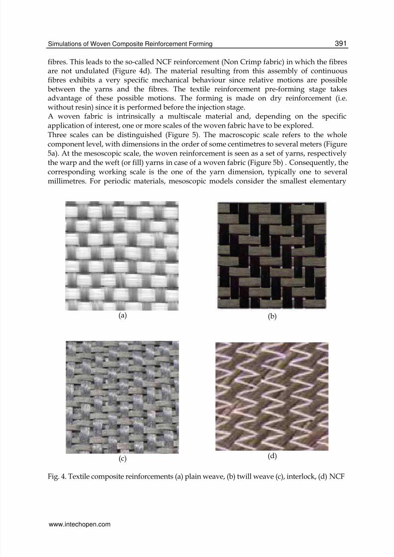
to 7 μm for carbon, 5 to 25 μm for glass, 10 to 20 μm for aramid. A yarn is made up of severalthousands juxtaposed fibres (usually 3. 103 to 96. 103). These yarns are woven followingstandard weaves (plain, satin, twill) or more complex structures such as braiding or ply toply interlock weaves (Figure 4c). An alternative consists in stitching a ply made of parallel
www.intechopen.com
7/28/2019 InTech-Simulations of Composite Reinforcement Forming
http://slidepdf.com/reader/full/intech-simulations-of-composite-reinforcement-forming 5/29
Simulations of Woven Composite Reinforcement Forming 391
fibres. This leads to the so-called NCF reinforcement (Non Crimp fabric) in which the fibresare not undulated (Figure 4d). The material resulting from this assembly of continuousfibres exhibits a very specific mechanical behaviour since relative motions are possiblebetween the yarns and the fibres. The textile reinforcement pre-forming stage takes
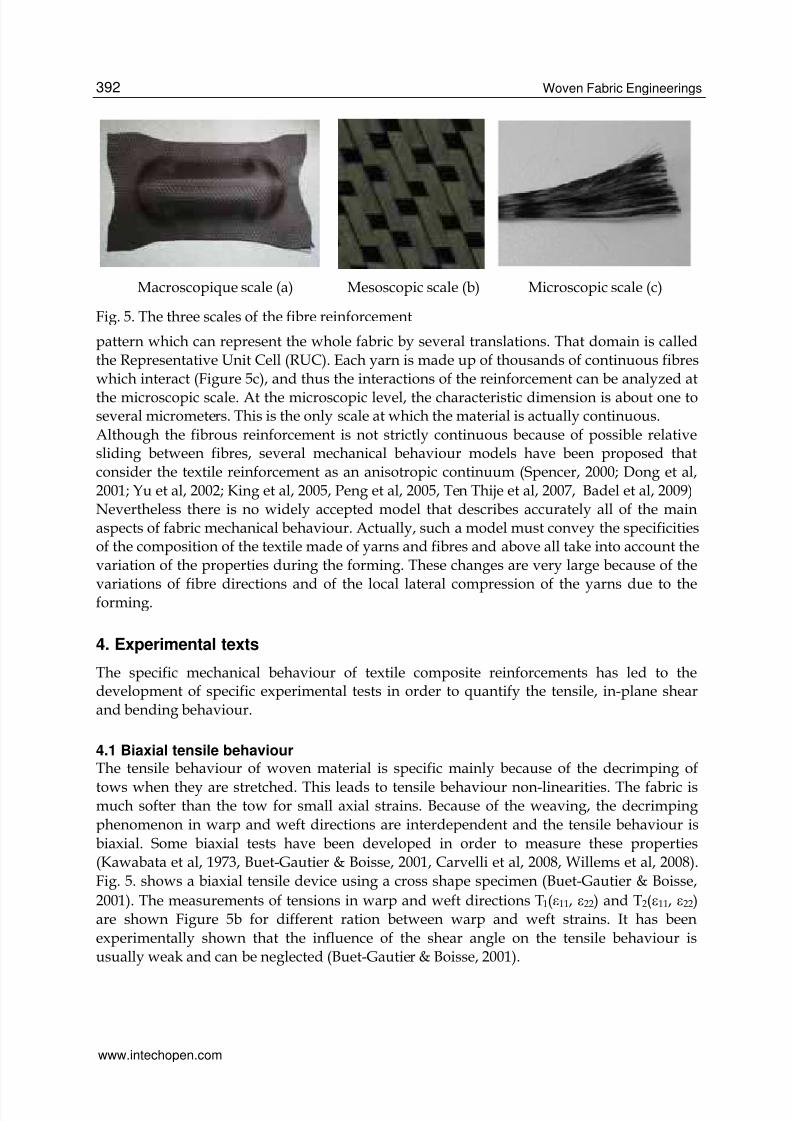
advantage of these possible motions. The forming is made on dry reinforcement (i.e.without resin) since it is performed before the injection stage.A woven fabric is intrinsically a multiscale material and, depending on the specificapplication of interest, one or more scales of the woven fabric have to be explored.Three scales can be distinguished (Figure 5). The macroscopic scale refers to the wholecomponent level, with dimensions in the order of some centimetres to several meters (Figure5a). At the mesoscopic scale, the woven reinforcement is seen as a set of yarns, respectivelythe warp and the weft (or fill) yarns in case of a woven fabric (Figure 5b) . Consequently, thecorresponding working scale is the one of the yarn dimension, typically one to severalmillimetres. For periodic materials, mesoscopic models consider the smallest elementary
(a) (b)
(c) (d)
Fig. 4. Textile composite reinforcements (a) plain weave, (b) twill weave (c), interlock, (d) NCF
www.intechopen.com
7/28/2019 InTech-Simulations of Composite Reinforcement Forming
http://slidepdf.com/reader/full/intech-simulations-of-composite-reinforcement-forming 6/29
Woven Fabric Engineerings392
Macroscopique scale (a) Mesoscopic scale (b) Microscopic scale (c)
Fig. 5. The three scales of the fibre reinforcement
pattern which can represent the whole fabric by several translations. That domain is calledthe Representative Unit Cell (RUC). Each yarn is made up of thousands of continuous fibreswhich interact (Figure 5c), and thus the interactions of the reinforcement can be analyzed at
the microscopic scale. At the microscopic level, the characteristic dimension is about one toseveral micrometers. This is the only scale at which the material is actually continuous.
Although the fibrous reinforcement is not strictly continuous because of possible relativesliding between fibres, several mechanical behaviour models have been proposed thatconsider the textile reinforcement as an anisotropic continuum (Spencer, 2000; Dong et al,2001; Yu et al, 2002; King et al, 2005, Peng et al, 2005, Ten Thije et al, 2007, Badel et al, 2009)Nevertheless there is no widely accepted model that describes accurately all of the mainaspects of fabric mechanical behaviour. Actually, such a model must convey the specificitiesof the composition of the textile made of yarns and fibres and above all take into account thevariation of the properties during the forming. These changes are very large because of the
variations of fibre directions and of the local lateral compression of the yarns due to theforming.
4. Experimental texts
The specific mechanical behaviour of textile composite reinforcements has led to thedevelopment of specific experimental tests in order to quantify the tensile, in-plane shearand bending behaviour.
4.1 Biaxial tensile behaviour
The tensile behaviour of woven material is specific mainly because of the decrimping of
tows when they are stretched. This leads to tensile behaviour non-linearities. The fabric ismuch softer than the tow for small axial strains. Because of the weaving, the decrimping
phenomenon in warp and weft directions are interdependent and the tensile behaviour is
biaxial. Some biaxial tests have been developed in order to measure these properties(Kawabata et al, 1973, Buet-Gautier & Boisse, 2001, Carvelli et al, 2008, Willems et al, 2008).
Fig. 5. shows a biaxial tensile device using a cross shape specimen (Buet-Gautier & Boisse,
2001). The measurements of tensions in warp and weft directions T1(ε11, ε22) and T2(ε11, ε22)are shown Figure 5b for different ration between warp and weft strains. It has been
experimentally shown that the influence of the shear angle on the tensile behaviour isusually weak and can be neglected (Buet-Gautier & Boisse, 2001).
www.intechopen.com

7/28/2019 InTech-Simulations of Composite Reinforcement Forming
http://slidepdf.com/reader/full/intech-simulations-of-composite-reinforcement-forming 7/29
Simulations of Woven Composite Reinforcement Forming 393
(a)
0
50
100
150
200
250
0 0.2 0.4 0.6
Strain (%)
L o a d ( N / y a r n )
Yarn
k=2
k=1
k=0.5
Otherdirection
free
(b)
Fig. 6. (a) Biaxial tensile test on cross-shaped specimen (b) Load versus strain for carbon
twill weave. k = εwarp / εweft (Buet-Gautier et al, 2001)
www.intechopen.com
7/28/2019 InTech-Simulations of Composite Reinforcement Forming
http://slidepdf.com/reader/full/intech-simulations-of-composite-reinforcement-forming 8/29
Woven Fabric Engineerings394
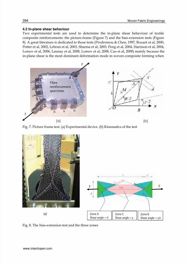
4.2 In-plane shear behaviourTwo experimental tests are used to determine the in-plane shear behaviour of textile
composite reinforcements: the picture-frame (Figure 7) and the bias-extension tests (Figure
8). A great literature is dedicated to those tests (Prodromou & Chen, 1997, Rozant et al, 2000,
Potter et al, 2002, Lebrun et al, 2003, Sharma et al, 2003, Peng et al, 2004, Harrison et al, 2004,Lomov et al, 2006, Launay et al, 2008, Lomov et al, 2008, Cao et al, 2008) mainly because the
in-plane shear is the most dominant deformation mode in woven composite forming when
Fig. 7. Picture frame test. (a) Experimental device. (b) Kinematics of the test
(a) (b)
F
Zone C
Shear angle = γ
F
Zone A
Shear angle = 0
Zone B
Shear angle = γ/2
Fig. 8. The bias-extension test and the three zones
www.intechopen.com

7/28/2019 InTech-Simulations of Composite Reinforcement Forming
http://slidepdf.com/reader/full/intech-simulations-of-composite-reinforcement-forming 9/29
Simulations of Woven Composite Reinforcement Forming 395
the manufactured part is doubly curved. The shear angle can reach 50° (and even more insome cases such as presented in section 5.6). For large values, wrinkling can occurdepending on the process parameters and on the material properties. In addition, the twotests are difficult both from the experimental point of view and concerning the
interpretation of the results. For these reasons an international benchmark has beenlaunched recently. Eight laboratories of six different countries have performed picture frameand bias-extension tests on the same textile composite reinforcements (Cao et al, 2008).The picture-frame (or trellis-frame) is made of four hinged bars. The fabric specimen isinitially square and the tows are parallel to the bars. Consequently it is theoretically
subjected to pure in-plane shear and the shear angle γ is function of the displacement d.
1 d2arccos
2 2L2
π ⎛ ⎞γ = − +⎜ ⎟
⎝ ⎠(1)
Neglecting the dissipation due to friction in the hinged bars, the in-plane shear moment on a
unit shell Ms is related to the force on the frame F using the equality of the powerexpressions. Sc is the surface of the unit woven cell in the initial state.
( ) cs
γ γSM γ = F cos - sin
2 22 L
⎛ ⎞⎜ ⎟⎝ ⎠
(2)
The bias-extension test is an alternative to the picture-frame test. It consists in clamping a
rectangular specimen of woven fabric with warp and weft directions initially oriented at 45°
with respect to the tensile load applied by a tensile machine (Figure 8). The initial length of
the specimen L must be larger than twice the width ℓ. The zone C in the centre of the
specimen is submitted to a pure shear γ if the yarns are assumed to be inextensible. That is a
correct assumption for the type of yarns used as composite reinforcements. This
inextensibility imposes that the shear angle in the zone B is half the value in the central
region C. The shear angle γ is related to the specimen elongation d in equation (c). The in-
plane shear moment is related to the force on the frame F in equation (d).
D d2arccos
2 2D
⎛ ⎞⎜ ⎟⎝ ⎠
π +γ = − (3)
( )
( )
FDScM cos sin Ms s2D 2 2 2D 2
γ γ γ⎛ ⎞ ⎛ ⎞γ = − −⎜ ⎟ ⎜ ⎟− −⎝ ⎠ ⎝ ⎠
`
` ` `(4)
A shear curve Ms(γ) measured in the case of glass plain weave is presented in Figure 9. In
the first part of the curve (i.e. for small shear angles), the in-plane shear stiffness is small. For
larger shear angles this rigidity increases and becomes significant. The optical field
measurements performed within the tow show that during the first part of the loading, the
tows rotate in a rigid body motion (Figure 9b). When the shear angle becomes larger lateral
contacts between the yarns occur (Dumont et al, 2003). The tows are progressively
compressed and the shear rigidity increases significantly. This increase of shear stiffness
leads to wrinkling onset. The corresponding shear angle is called locking angle (in order of
40°- 45° for textile composite reinforcements (Prodromou & Chen, 1997, Cao et al, 2008).
www.intechopen.com

7/28/2019 InTech-Simulations of Composite Reinforcement Forming
http://slidepdf.com/reader/full/intech-simulations-of-composite-reinforcement-forming 10/29
Woven Fabric Engineerings396
Fig. 9. (a) Shear curve of glass plain weave, (b) relative displacement field inside a yarn
4.3 Bending behaviourThe bending stiffness of the fibrous reinforcement is very low due to the possible motionbetween fibres. It is often neglected and membrane approaches are often used. Neverthelessthis bending stiffness is important to obtain accurate wrinkle shape. Specific tests have beendeveloped for these textile materials, the bending stiffness of which is much smaller than theone given by the plate theory (Kawabata, 1986, Lahey and Heppler 2004, de Bilbao et al,2010). Figure 10 shows a cantilever bending test (de Bilbao et al, 2010). The own weight ofthe fabric defines the bending moments for a given length of the specimen. The curvatures
are deduced from the measured geometry. These measurements, made for different lengthof a specimen give the bending moment in function of the curvature. They are made in warpand weft directions.
5. Continuous approach for the simulation of textile composite forming
In the continuous approaches, a woven fabric is seen as a continuous material with a specific
mechanical behaviour, including high anisotropy and the ability to exhibit very large
shearing and bending deformations. Investigation at the macroscopic level is the most
popular for reinforcement forming simulations, as it allows using finite elements codes with
standard shell or membrane elements and does not ask the description of the internal textile
material structure. Despite the large amount of work in this field (Spencer, 2000; Dong et al,2001; Yu et al, 2002; King et al, 2005, Peng et al, 2005, Ten Thije et al, 2007, Badel et al, 2009)
there is no widely accepted model that accurately describes all aspects of the mechanical
behaviour of fabrics. Two continuous approaches are described below.
5.1 Hyperelastic behaviour
The formulation of a hyperelastic behaviour law lies on the proposition of a potential energyfrom which derives the hyperelastic constitutive model. This potential aims to reproduce thenon linear mechanical behaviour of textile composite reinforcements. The proposedpotential is a function of the right Cauchy Green and structural tensor invariants defined
www.intechopen.com

7/28/2019 InTech-Simulations of Composite Reinforcement Forming
http://slidepdf.com/reader/full/intech-simulations-of-composite-reinforcement-forming 11/29
Simulations of Woven Composite Reinforcement Forming 397
Fig. 10. Cantilever bending test
from the fibre directions. This potential is based on the assumption that tensile and shear
strain energies are uncoupled. It is the sum of three terms.
1 1 2 2 s 12W W (I ) W (I ) W (I )= + + (5)
This assumption (tensile and shear strain energies are uncoupled) are made for sake ofsimplicity. The independence of tensile behaviour relatively to in plane shear has beenshown experimentally (Buet-Gauthier and Boisse, 2001). The other hypotheses are probablyless true, but there are made for sake of simplicity and because there are few data availableon some couplings.
The structural tensors Lαβ
are defined from the two unit vectors in the warp and weft
directions10
f and20
f in the reference configuration C0 (figure 11):
L f f0 0= ⊗α βαβ(6)
The two first terms 1W and 2W are the energies due to the tensions in the yarns. They arefunction of invariants I1 and I2 respectively, themselves depending on the right Cauchy
Green strain tensor TC F F= ⋅ and the structural tensors Lαα
:
2 21 11 1 2 22 2I Tr(C L ) I Tr(C L )= ⋅ = λ = ⋅ = λ (7)
αλ is the deformed length of on initially unit fibre in the direction α.
www.intechopen.com
7/28/2019 InTech-Simulations of Composite Reinforcement Forming
http://slidepdf.com/reader/full/intech-simulations-of-composite-reinforcement-forming 12/29
Woven Fabric Engineerings398
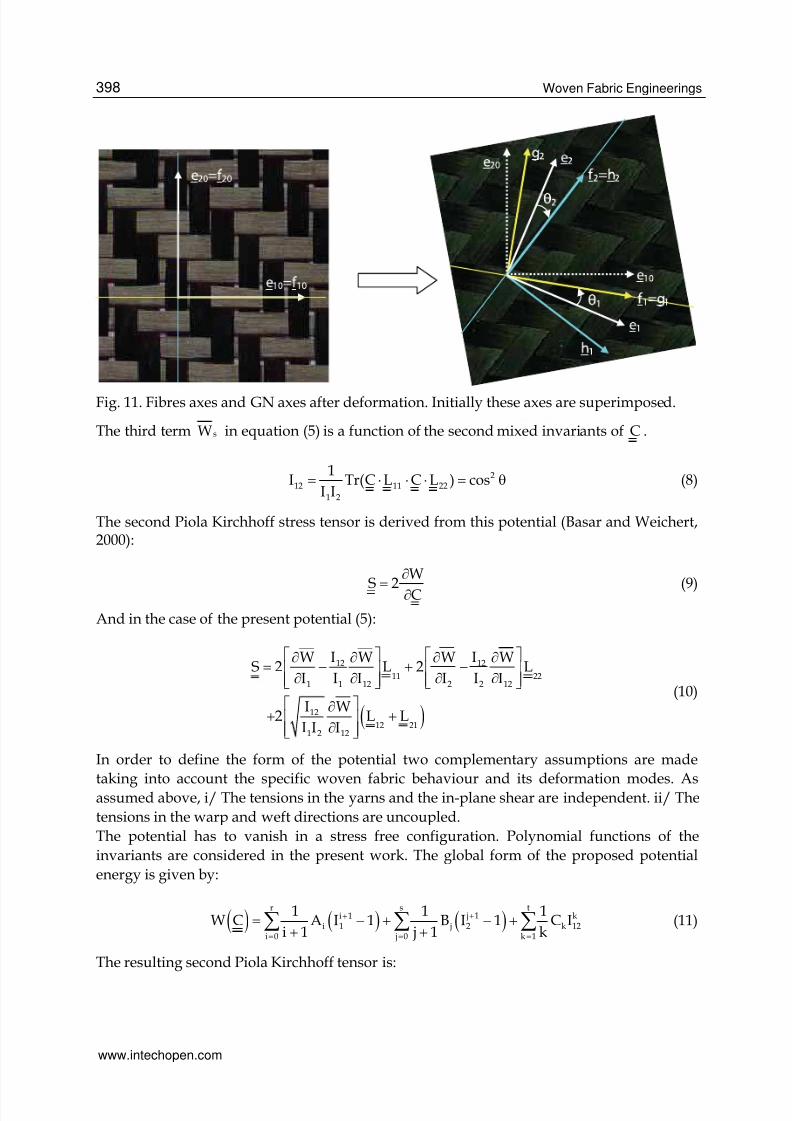
Fig. 11. Fibres axes and GN axes after deformation. Initially these axes are superimposed.
The third term sW in equation (5) is a function of the second mixed invariants of C .
212 11 22
1 2
1I Tr(C L C L ) cos
I I= ⋅ ⋅ ⋅ = θ (8)
The second Piola Kirchhoff stress tensor is derived from this potential (Basar and Weichert,2000):
W
S 2 C
∂
= ∂ (9)
And in the case of the present potential (5):
( )
12 12
11 221 1 12 2 2 12
12
12 211 2 12
W I W W I WS 2 L 2 L
I I I I I I
I W2 L L
I I I
⎡ ⎤ ⎡ ⎤∂ ∂ ∂ ∂= − + −⎢ ⎥ ⎢ ⎥
∂ ∂ ∂ ∂⎢ ⎥ ⎢ ⎥⎣ ⎦ ⎣ ⎦
⎡ ⎤∂+ +⎢ ⎥
∂⎢ ⎥⎣ ⎦
(10)
In order to define the form of the potential two complementary assumptions are made
taking into account the specific woven fabric behaviour and its deformation modes. Asassumed above, i/ The tensions in the yarns and the in-plane shear are independent. ii/ The
tensions in the warp and weft directions are uncoupled.
The potential has to vanish in a stress free configuration. Polynomial functions of the
invariants are considered in the present work. The global form of the proposed potential
energy is given by:
( ) ( ) ( )r s t
j 1i 1 ki 1 j 2 k 12
i 0 j 0 k 1
1 1 1W C A I 1 B I 1 C I
i 1 j 1 k++
= = =
= − + − ++ +∑ ∑ ∑ (11)
The resulting second Piola Kirchhoff tensor is:
www.intechopen.com

7/28/2019 InTech-Simulations of Composite Reinforcement Forming
http://slidepdf.com/reader/full/intech-simulations-of-composite-reinforcement-forming 13/29
Simulations of Woven Composite Reinforcement Forming 399
( )
r t s t ji k k
i 1 k 12 j 2 k 1211 22i 0 k 1 j 0 k 11 2
tk 1/2
k 12 12 21k 11 2
1 1S 2 A I C I L 2 B I C I L
I I
1
2 C I L LI I
= = = =
−
=
⎛ ⎞⎛ ⎞= − + −⎜ ⎟⎜ ⎟ ⎜ ⎟
⎝ ⎠ ⎝ ⎠⎛ ⎞
+ +⎜ ⎟⎜ ⎟⎝ ⎠
∑ ∑ ∑ ∑
∑
(12)
For strain-free configuration, stresses have to vanish. This condition imposes:
r s
i ji 0 j 0
A 0 ; B 0= =
= =∑ ∑ (13)
To determine the constants Ai, B j and Ck, three experimental tests are necessary: two tensiletests in the warp and weft directions and one in-plane pure shear test. The details of thecalculations to obtain equations ??? to ??? are given in (Aimene et al, 2010). In this paper it isalso shown that the form of the potential given above gives correct results concerning the
direction of the loads on the boundary of a picture frame while other forms of the potentiallead to boundary loads that are not correct for a woven fabric.The proposed hyperelastic model is implemented in a user routine VUMAT ofAbaqus/Explicit and it is applied to membrane elements. The simulation of a hemisphericalpunch forming process is performed in the case of strongly unbalanced twill (Daniel et al,2003). The warp rigidity is 50 N/yarn and the weft rigidity is 0.2 N/yarn. The experimentaldeformed shape are shown figure 12 (a) together with the results of the simulation figure 12(c). The computed deformed shape (made using the hyperelastic model proposed above) isin correct agreement with the experimental one. Especially the strong difference of thedeformation in warp and weft directions is well verified.
5.2 Hypoelastic behaviourHypoelastic models have been proposed for material at large strain (Truesdell, 1955, Xiao etal, 1988)
∇ =C : D (14)
where D and C are the strain rate tensor and the constitutive tensor, respectively. ∇σ ,
called the objective derivative of the stress tensor, is the time derivative for an observer whois fixed with respect to the material.
( )T Td
dt∇ ⎛ ⎞= ⋅ ⋅ ⋅ ⋅⎜ ⎟
⎝ ⎠Q Q Q Qσ (15)
Q is the rotation from the initial orthogonal frame to the so-called rotating frame where the
objective derivative is made. The most common objective derivatives are those of Green-Naghdi and Jaumann. They use the rotation of the polar decomposition of the deformationgradient tensor ⋅F =R U , (standard in Abaqus explicit), and the corotational frame,
respectively. These are routinely used for analyses of metals at finite strains (Belytschko etal, 2000). It has been shown that, in the case of a material with one fibre direction the properobjective rotational derivative is based on the rotation of the fibre (Badel et al, 2009)
www.intechopen.com

7/28/2019 InTech-Simulations of Composite Reinforcement Forming
http://slidepdf.com/reader/full/intech-simulations-of-composite-reinforcement-forming 14/29
Woven Fabric Engineerings400
Fig. 12. Deformed shape in the case of an unbalanced fabric (experimental shape (a); Resultof the simulation (c))
A membrane assumption is used. The Green-Naghdi’s frame (GN) is the default work basisof ABAQUS/Explicit. Its unit vectors 1 2( , )e e in the current configuration are updated from
the initial orientation axes, 0 01 2( , )e e using the proper rotation R :
0 01 1 2 2 = ⋅ = ⋅e R e e R e (16)
In the current configuration, the unit vectors in the warp and weft fibre directions arerespectively:
1
1
1
=0
0
F.f f
F.f
2
2
2
=0
0
F.f f
F.f (17)
Where 0 01 2( , )e e and 0 0
1 2( , )f f are assumed to coincide initially (Figure 3). Two orthonormal
frames based on the two fibre directions are defined: ( )1 2
g ,g g with11,=g f and
( )1 2h ,h h with 2 2=h f (Figure 11).
The strain increment dε is given as a code’s output in calculation loop from time tn to time
tn+1. (The matrix of the components of this strain increment is given in the GN frame in thecase of Abaqus explicit, but it could be any other frame). The components of the strainincrement in the two frames g and h are considered (α and β are indexes taking value 1 or2):
g hd d α βαβ αβα β
= ε ⊗ = ε ⊗dε g g h h
(18)
The fibre stretching strain and the shear strain are calculated for the two frames g and h.
www.intechopen.com

7/28/2019 InTech-Simulations of Composite Reinforcement Forming
http://slidepdf.com/reader/full/intech-simulations-of-composite-reinforcement-forming 15/29
Simulations of Woven Composite Reinforcement Forming 401
g
11 1 1dε = ⋅ ⋅g dε g
g
12 1 2dε = ⋅ ⋅g dε g (19)
h
2 222dε = ⋅ ⋅h dε h
h
1 212dε = ⋅ ⋅h dε h (20)
From these strain components the axial stress component and shear stress components arecalculated in each frame g and h:
g g g
11 11d E dσ = ε
g g
12 12d Gdσ = ε
(21)
h h h
22 22d E dσ = ε
h h
12 12d Gdσ = ε (22)
Eg and Eh are the stiffness in the warp and weft fibre directions respectively and G the in-plane shear stiffness of the fabric (They are not constant, especially G depends strongly onthe in plane shear). Following the scheme of Hughes and Winget the stresses are then
integrated on the time increment from time tn to time tn+1 (Hughes & Winget, 1980):
( ) ( )n 1/ 2n 1 n
g g g
11 11 11d++
σ = σ + σ
( ) ( )n 1/ 2n 1 n
g g g
12 12 12d++
σ = σ + σ
(23)
( ) ( )n 1/ 2n 1 n
h h h
11 11 11d++
σ = σ + σ
( ) ( )n 1/ 2n 1 n
h h h
12 12 12d++
σ = σ + σ (24)
The stress at time tn+1 in the fabric is the addition of the stresses in the two fibre frames:
( ) ( )
n 1 n 1n 1 g h
+ ++ = +σ σ σ
(25)
For instance, denotinge
α βαβ= σ ⊗σ e e and omitting the superscript n+1 because all thequantities are at time tn+1, the components of the Cauchy stress tensor in the GN frame (thatare requested in the Abaqus Explicit code) are:
( ) ( ) ( )( ) ( ) ( )( )( )
g ge h2 211 22 121 1 1 2
h1 212
e .g e .g e .h e .h e .g e .g
e .h e .h
αβ α β α β α β
α β
σ = σ + σ + σ
+σ(26)
More detail on this approach can be found in (Badel et al, 2009, Khan et al, 2010). Thisapproach is used to simulate the forming double dome shape corresponding to an
international benchmark (Khan et al, 2010). An experimental device has been realised inINSA Lyon in order to perform this forming (Figure 13). The woven fabric is a commingledglass/polypropylene plain weave that has been tested in the material benchmark studyconducted recently (Cao et al, 2008). The computed and experimental geometries afterforming are compared figure 14 and 15. The measured and numerical geometries and shearangles are in good agreement.
6. Discrete approach for the composite reinforcement forming
In discrete modelling (also called meso-modelling in the case of textile material), themodelling does not directly concern the textile material but each fibre bundle. This one is
www.intechopen.com

7/28/2019 InTech-Simulations of Composite Reinforcement Forming
http://slidepdf.com/reader/full/intech-simulations-of-composite-reinforcement-forming 16/29
Woven Fabric Engineerings402
Fig. 13. Double dome forming: experimental device
1
5 6 7
10
8
3
2
4
9
°
°
°
° ° ° °
°
°
°
Fig. 14. Experimental and numerical outputs of double dome forming test
www.intechopen.com

7/28/2019 InTech-Simulations of Composite Reinforcement Forming
http://slidepdf.com/reader/full/intech-simulations-of-composite-reinforcement-forming 17/29
Simulations of Woven Composite Reinforcement Forming 403
0
5
10
15
20
25
30
35
40
45
50
1 2 3 4 5 6 7 8 9 10
S h e a r A n g l e ( d e g . )
Shear Angle Locations
Numerical Experimental (OSM)
Fig. 15. Comparison of numerical and experimental shear angles at the locations shown inFigure 14.
modelled by elements simple enough to render the computation possible because it
concerns the forming of the whole composite reinforcement and the number of yarns andcontacts between these yarns is very large. The interactions between warp and weftdirections are taken into account explicitly by considering contact behaviour and relativemotions between the yarns are possible (Pickett et al, 2005, Duhovic et al, 2006, BenBoukaber et al 2007).At the microscopic level, each fibre is satisfactorily described as a beam but this approach istime consuming. The main difficulty is the great number of contacts with friction that haveto be taken into account, especially for a woven fabric. For this reason, only very smallelements of the fabric have been modelled to date (Durville, 2005, Miao et al, 2008).Nevertheless, this approach is promising because it does not necessitate any assumptionsregarding the continuity of the material, the specific mechanical properties resulting at the
macroscopic level naturally follow the displacements and deformations of the yarns and itprovides an interesting way of taking the weaving operation into account. The fibresconstituting the yarns can be modelled directly, but their very large number (3K to 48K peryarn) requires that the computations are made for a number of fibres per yarn significantlysmaller than in reality. An alternative possibility is to use a continuous behaviour for eachyarn (meso-modelling). This implies that the fibrous nature of the yarn is taken into accountin this model especially in order to have rigidities in bending and transverse compressionvery small in comparison to the tensile stiffness. In any case, a compromise must be foundbetween a fine description (which will be expensive from the computation time point ofview) and a model simple enough to compute the entire forming process. Figure 16(b) show
www.intechopen.com

7/28/2019 InTech-Simulations of Composite Reinforcement Forming
http://slidepdf.com/reader/full/intech-simulations-of-composite-reinforcement-forming 18/29
Woven Fabric Engineerings404
(a) (b)
Fig. 16. Meso-modelling of a unit cell of a plain weave. (a) FE model for the analysis of thebehaviour of the unit cell. 47214 Dof. (b) FE model for simulations of the whole compositereinforcement forming. 216 Dof.
the finite element model used for discrete simulations of forming processes (216 dof
(degrees of freedom)). It is compared to another FE model of the unit cell used in (Badel etal, 2009)(Figure 16(a)) to analyze the local in plane shear of a plain weave unit cell (47214dof). It cannot be considered (at least today) to use this last FE model to simulate theforming of a composite reinforcement that is made of several thousands of woven cells. Inthe simplified unit cell (Figure 16(b)) each yarn is described by few shell elements and thecontact friction and possible relative displacement of the yarns are considered. The in-planemechanical behaviour is the same as the one defined in (Badel et al, 2009). The bendingstiffness is independent of the tensile one and very much reduced in comparison to the onegiven by plate theories.Two examples are presented in figures 17 and 18 based on a discrete modelling using theunit cell of figure 16(b) (Gatouillat et al, 2010) The first one is a picture frame test for which
the wrinkles appear naturally in the simulation when the shear locking angle is reached. Itmust be noticed that the in-plane shear behaviour of the fabric is not an input data of theanalysis and does not need to be known. It results at the macroscopic level of contact andfriction between the yarns and lateral compression of the yarns. Figure 18 shows the resultsof a hemispherical forming simulation. It must be said that this study concerning formingsimulation at the meso-scopic scale is beginning at INSA Lyon. If the discrete or mesoscopicmodelling is a promising approach because a large part of the mechanical specificity offabric behaviour is due to yarn and fibre interactions, and following fibre directions issimpler than for continuous models, it must be recognized that the forming simulationsmade with approaches that permits the relative sliding of the yarns in contact are not many.
7. The semi-discrete finite elements for the composite reinforcement forming
This approach can be seen as intermediate between the continuous and the discreteapproaches. The textile composite reinforcement is seen as a set of a discrete number of unitwoven cells submitted to membrane loadings (i.e. biaxial tension and in-plane shear) andbending (Figure 19)(Hamila et al, 2009)
In any virtual displacement field η such as η = 0 on the boundary with prescribed loads, thevirtual work theorem relates the internal, exterior and acceleration virtual works:
ext int accW ( ) W ( ) W ( )η − η = η (27)
www.intechopen.com

7/28/2019 InTech-Simulations of Composite Reinforcement Forming
http://slidepdf.com/reader/full/intech-simulations-of-composite-reinforcement-forming 19/29
Simulations of Woven Composite Reinforcement Forming 405
Fig. 17. Simulation of a picture frame test using the unit cell model of figure 16(b)
Fig. 18. Simulation of hemispherical forming test using the unit cell model of figure 16(b)
www.intechopen.com
7/28/2019 InTech-Simulations of Composite Reinforcement Forming
http://slidepdf.com/reader/full/intech-simulations-of-composite-reinforcement-forming 20/29
Woven Fabric Engineerings406
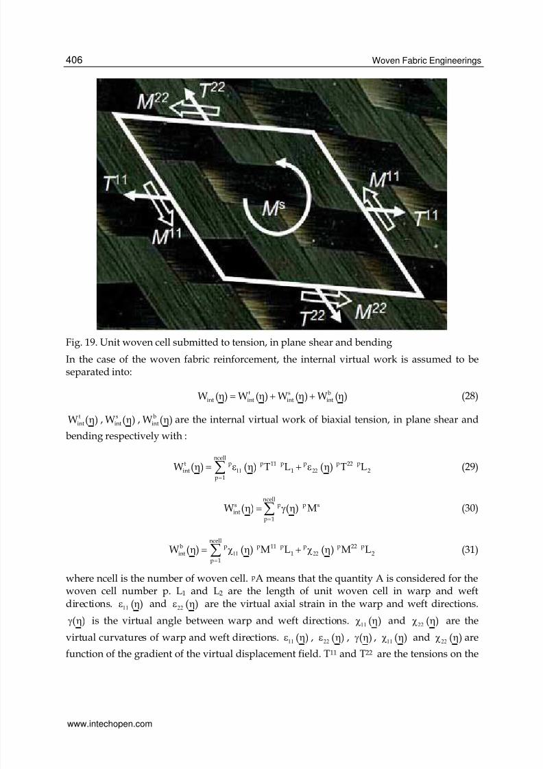
Fig. 19. Unit woven cell submitted to tension, in plane shear and bending
In the case of the woven fabric reinforcement, the internal virtual work is assumed to beseparated into:
t s bint int int intW ( ) W ( ) W ( ) W ( )η = η + η + η (28)
tintW ( )η , s
intW ( )η , bintW ( )η are the internal virtual work of biaxial tension, in plane shear and
bending respectively with :
ncellp p p p p pt 11 22
int 1 2p 1
W ( ) ( ) T L ( ) T L11 22=
η = ε η + ε η∑ (29)
ncellp ps s
intp 1
W ( ) ( ) M=
η = γ η∑ (30)
ncellp p p p p pb 11 22
int 1 2p 1
W ( ) ( ) M L ( ) M L11 22=
η = χ η + χ η∑ (31)
where ncell is the number of woven cell. pA means that the quantity A is considered for thewoven cell number p. L1 and L2 are the length of unit woven cell in warp and weftdirections. ( )11ε η and ( )22ε η are the virtual axial strain in the warp and weft directions.
( )γ η is the virtual angle between warp and weft directions. ( )11χ η and ( )22χ η are the
virtual curvatures of warp and weft directions. ( )11ε η , ( )22ε η , ( )γ η , ( )11χ η and ( )22χ η are
function of the gradient of the virtual displacement field. T11 and T22 are the tensions on the
www.intechopen.com
7/28/2019 InTech-Simulations of Composite Reinforcement Forming
http://slidepdf.com/reader/full/intech-simulations-of-composite-reinforcement-forming 21/29
Simulations of Woven Composite Reinforcement Forming 407
unit woven cell in warp and weft directions. M11 and M22 are the bending moments on thewoven cell respectively in warp and weft directions. Ms is the in-plane shear moment. Theloads on an edge of the woven unit cell (presented Figure 19) result in the tensions T11 andT22 in one hand and shear forces in the other hand. This shear forces on a warp and weft
sections have a moment at the centre of the woven unit cell in the direction normal to theunit cell. The component of this moment is called in-plane shear moment Ms. This quantity
is conjugated to the in-plane shear angle γ . The internal virtual work of in plane shear isdirectly given from Ms and the virtual shear angle (Equation 30). In the case of a textile
material, the shear angle γ is a significant and clearly defined quantity and it is interesting toexpress the internal virtual work of in plane shear in function of this quantity.The mechanical behaviour of the textile reinforcement defines a relation between the loadsTαα, Ms, Mαα and the strain field. The experimental tests specific to textile compositereinforcements that have been presented in Section 4 are used to obtain T11, T22, Ms, M11andM22 in function of ε11, ε22, γ, χ11 and χ22. An alternative consists in virtual tests i.e. in 3D simulations of the deformation of a unit
woven cell submitted to elementary loadings such as biaxial tensions or in plane shear(Badel et al, 2008, Badel et al, 2009)
7.1 Shell finite element made of woven cellsA three node shell finite element have been defined from the simplified form of the principleof virtual works given in equations 28 to 31. The details of its formulation are given in(Hamila et al, 2009). It is summarized below.A finite element interpolation is introduced within the principle of virtual work. Thedisplacement u and virtual displacement η of any point within an element are in the form:
eu =Nu and eη =Nη (32)
N is the interpolation matrix of the element under consideration and eu and eη the single
column matrices of its nodal displacements and virtual displacements respectively.
Equation 28 leads to:
( )t s bint int int ext 0+ + + − =Mu F F F F$$ (33)
M is the mass matrix, u is the single column matrices of the nodal displacements. t s bint int int, ,F F F
are the single column matrices of the nodal internal forces respectively for tension, shear
and bending.This dynamic equation can be solved using an explicit scheme (central differences):
( )i 1 i 1 i ti si biD ext int int int
+ −= − − −u M F F F F$$ (34)
( )i 1 2 i 1 2 i 1 i i 11t t
2+ − − += + Δ + Δu u u$ $ $$ (35)
i 1 2i 1 i it++ = + Δu u u$ (36)
There is no system to solve since MD is a diagonal matrix calculated fromM (Zienkiewicz &Taylor, 2000). This explicit scheme requires the time step to be small enough to insure the
www.intechopen.com

7/28/2019 InTech-Simulations of Composite Reinforcement Forming
http://slidepdf.com/reader/full/intech-simulations-of-composite-reinforcement-forming 22/29
Woven Fabric Engineerings408
stability of the scheme (Belytschko, 1983). It is effective for many dynamic applications andalso in material forming. For the sake of numerical efficiency, the speed can be larger thanthe real one under the condition that the dynamic effects do not modify the solution.The 3 node shell finite element M1M2M3 made up of ncelle woven cells is considered (Figure
20). The vectors k1=AM2 and k2=BM3 respectively in warp and weft directions are defined.The internal virtual work of tension on the element defines the element nodal tensile
internal forces teintF :
ncellep p p p p p eT te
1 1 2 2 intp 1
( ) T L ( ) T L11 22=
ε η + ε η =∑ η F (37)
The internal tensile force components are calculated from the tensions T1 and T2:
( )te 1 2int 1ij 1 2ij 22 2ij
1 2
L LF ncelle B T B T
k k
⎛ ⎞⎜ ⎟= +
⎜ ⎟⎝ ⎠
(38)
i is the index of the direction (i=1 to 3), j is the index of the node (j=1 to 3). B 1ij and B2ij arestrain interpolation components. They are constant over the element because theinterpolation functions in equation 32 are linear in the case of the 3 node triangle.The internal virtual work of in-plane shear on the element defines the element nodal tensile
internal forces seintF :
ncellep p eT se
s intp 1
( ) M=
γ η =∑ η F (39)
The internal in-plane shear force components are calculated from the in-plane shear moment:
( ) ( )se sint ijij
F ncelle B Mγ= γ (40)
In order to avoid supplementary degrees of freedom and consequently for numericalefficiency, the bending stiffness is taken into account within an approach without rotationaldegree of freedom (Onate & Zarate, 2000, Sabourin et Brunet, 2006). In theses approachesthe curvatures of the element are computed from the positions and displacements of thenodes of the neighbouring elements (Figure 20). The internal virtual work of bending on the
element defines the element nodal bending internal forces beintF :
ncellep p p p p p eT be
1 1 2 2 intp 1
( ) M L ( ) M L11 22=
χ η + χ η =∑ η F (41)
The internal bending force components are calculated from the bending moments M1 and M2:
( )be 1 2int celle 1km 1 2km 22 2km
1 2
L LF n Bb M Bb M
k k
⎛ ⎞⎜ ⎟= +⎜ ⎟⎝ ⎠
(42)
The finite element presented above is used to simulate the hemispherical forming of thevery unbalanced fabric presented in section 5.1. The experimental forming by a
www.intechopen.com

7/28/2019 InTech-Simulations of Composite Reinforcement Forming
http://slidepdf.com/reader/full/intech-simulations-of-composite-reinforcement-forming 23/29
Simulations of Woven Composite Reinforcement Forming 409
Fig. 20. Three node finite element made of unit woven cells,
(a)
(b) (c)
Fig. 21. Forming of an unbalanced textile reinforcement
hemispherical punch has been performed at the University of Nottingham (Daniel et al,2003). A 6 kg ring was used as blank-holder avoiding reinforcement wrinkling in thehemispherical zone (Figure 21a). The experimental shape obtained after forming is shown inFigure 21b. In warp direction (with the strongest rigidity) large fabric sliding is observedrelatively to the die. On the contrary, in the weft direction (weak direction) no edge
www.intechopen.com

7/28/2019 InTech-Simulations of Composite Reinforcement Forming
http://slidepdf.com/reader/full/intech-simulations-of-composite-reinforcement-forming 24/29
Woven Fabric Engineerings410
movement is depicted and the yarns are subjected to large stretch deformations. Thecomputed shape after forming is shown in Figure 21c. It is in good agreement withexperiments. Especially the extension ratio at the centre of the hemisphere (lweft/lwarp = 1.8)is correctly computed. The shape of the many wrinkles in the flat part of the textile is also
properly simulated.
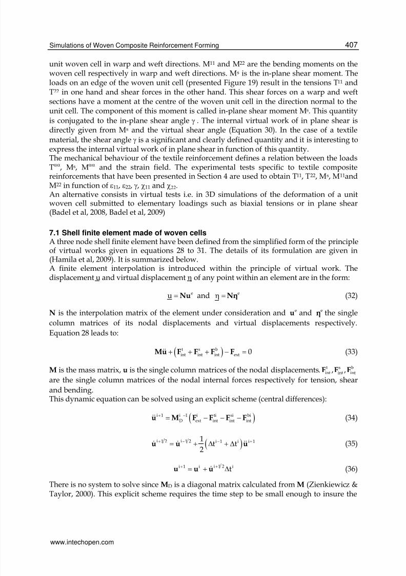
7.2 Extension to 3D interlock textile reinforcementsWhen the thickness of a composite part is large, the use of these laminated composites isrestricted by manufacturing problems and their low resistance to delamination cracking. Toovercome these difficulties composites with 3D fibre architecture called ply to ply interlockfabric have been proposed (Tong et al, 2002). This material is not fully 3D since there is nothird yarn set in the transverse direction but the properties through the thickness are muchimproved. Above all, the possible delaminations of the 2D laminated composites areovercome. (Figure 22). The semi-discrete approach has been extended to 3D hexahedralfinite elements for interlock forming simulations; These elements are made of yarns asshown Figure 23. The simulation of a thick twisted plate made of interlock textilereinforcement is shown figure 24. The formulation of these finite elements for interlockforming simulations is given in (De Luycker et al, 2009).
Fig. 22. Example of complex layer interlock weave
Fig. 23. Height node hexahedral finite element containing yarns – (a) Initial state–(b) Deformed state.
www.intechopen.com
7/28/2019 InTech-Simulations of Composite Reinforcement Forming
http://slidepdf.com/reader/full/intech-simulations-of-composite-reinforcement-forming 25/29
Simulations of Woven Composite Reinforcement Forming 411
Fig. 24. Forming of a 3D interlock twisted plate
8. Conclusion
Different approaches for composite forming simulations have been presented in thischapter. They are continuous discrete or semi-discrete element. These different approachesare based on the strong multi-scale nature of the textile reinforcements.The discrete approach is attractive and promising. The very specific mechanical behaviourof the textile material due to the contacts and friction between the yarns and to the change ofdirection is explicitly taken into account. If some sliding occurs between warp and weftyarns, they can be simulated. This is not possible by the continuous approaches thatconsider the textile material as a continuum. This is an important point because it can benecessary to prevent such a sliding in a process. Nevertheless, the main difficulty of thediscrete approach is the necessary compromise that must be done between the accuracy ofthe model of the unit woven cell and the total number of degrees of freedom. The modellingof the unit cell must be accurate enough to obtain a correct macroscopic mechanicalbehaviour, but the number of degrees of freedom of each cell must remain small in order tocompute a forming process for which there will be thousand of woven cells. There are a lotof improvements to achieve in the meso-modelling of different textile reinforcements. Thecontinuous increase of the computer power is a strong argument in favour of this approach.The continuous approach is the most commonly used in composite reinforcement formingtoday. The main advantage is to use standard shell or membrane finite element. The onlymechanical behaviour has to be specified in order to take the very particular behaviour oftextile materials into account. Many models exist, but none of them is clearly admitted. Thesemi-discrete approach aims to avoid the use of stress tensors and directly define the
loading on a woven unit cell by the warp and weft tensions and by in-plane shear andbending moments. These quantities are simply defined on a woven unit cell and above allthey are directly measured by standard tests on composite reinforcements (biaxial tension,picture frame, bias extension and bending tests).
9. References
Advani SG. Flow and rheology in polymeric composites manufacturing. Elsevier, 1994.Aimène Y, Vidal-Sallé E, Hagège B, Sidoroff F, Boisse P, A hyperelastic approach for
composite reinforcement large deformation analysis, Journal of CompositeMaterials Vol. 44, No. 1/2010, 5-26
www.intechopen.com
7/28/2019 InTech-Simulations of Composite Reinforcement Forming
http://slidepdf.com/reader/full/intech-simulations-of-composite-reinforcement-forming 26/29
Woven Fabric Engineerings412
Badel P, Vidal-Sallé E, Maire E, Boisse P (2009) Simulation and tomography analysis oftextile composite reinforcement deformation at the mesoscopic scale. CompositesScience and Technology 68:2433-2440
Badel P, Gauthier S, Vidal-Salle E, Boisse P. Rate constitutive equations for computational
analyses of textile composite reinforcement mechanical behaviour during forming.Composites: Part A 40 (2009) 997–1007
Basar Y, Weichert D (2000) Nonlinear continuum mechanics of solids. Springer, BerlinBelytschko T. An overview of semidiscretisation and time integration procedures. In:
Belytschko T, Hughes TJR, editors, Computation Methods for Transient Analysis.Amsterdam: Elsevier, 1983.
Ben Boukaber B, Haussy G, Ganghoffer JF (2007) Discrete models of woven structures.Macroscopic approach. Composites: Part B 38:498-505
Borouchaki H, Cherouat A. Une nouvelle approche pour le drappage des structurescomposites. Rev Comp Mat Avanc 2002;32:407–22
Buet-Gautier K., Boisse P. Experimental analysis and modeling of biaxial mechanical
behavior of woven composite reinforcements. Experimental Mechanics 2001; 41 (3):260-269.
Cao J., Akkerman R., Boisse P., Chen J. et al. Characterization of Mechanical Behavior ofWoven Fabrics: Experimental Methods and Benchmark Results. Composites Part A2008; 39: 1037-1053.
Carvelli V., Corazza C., Poggi C. Mechanical modelling of monofilament technical textiles.Computational Materials Science 2008; 42: 679-691.
Dong L, Lekakou C, Bader MG. Processing of composites: simulations of the draping offabrics with updated material behaviour law. Journal of Composite Materials 2001;35: 38–163.
Daniel JL, Soulat D, Dumont F, Zouari B, Boisse P, Long AC, Forming simulation of veryunbalanced woven composite reinforcements. International Journal of FormingProcesses 2003, 6:465-480
de Bilbao E, Soulat D, Hivet G, Gasser A., Experimental Study of Bending Behaviour ofReinforcements, Experimental Mechanics (2010) 50:333–351
De Luycker E, F. Morestin, P. Boisse, D. Marsal, Simulation of 3D interlock compositepreforming, Composite Structures, 88, Issue 4, May 2009, Pages 615-623
Duhovic M, Bhattacharyya D (2006) Simulating the deformation mechanisms of knittedfabric composites. Composites: Part A 37:1897-1915
Dumont F, Hivet G, Rotinat R, Launay J, Boisse P, Vacher P. Field measurements for sheartests on woven reinforcements. Mécanique et Industrie, 2003; 4:627–35.
Durville D, 2005, Numerical simulation of entangled materials mechanical properties. Journal of Materials Science 40:5941-5948
Gatouillat S, Vidal-Salle E, Boisse P, Advantages of the meso/macro approach for thesimulation of fibre composite reinforcements, Proceedings of the ESAFORM 2010Conference, Brescia, April 2010, Italy
Hamila N., Boisse P., Sabourin F., Brunet M. A semi-discrete shell finite element for textilecomposite reinforcement forming simulation. Int J Numerical Methods inEngineering 2009; 79: 1443-1466.
www.intechopen.com

7/28/2019 InTech-Simulations of Composite Reinforcement Forming
http://slidepdf.com/reader/full/intech-simulations-of-composite-reinforcement-forming 27/29
Simulations of Woven Composite Reinforcement Forming 413
Harrison P., Clifford MJ., Long AC. Shear characterisation of viscous woven textilecomposites: a comparison between picture frame and bias extension experiments.Compos Sci Tech 2004; 64: 1453-1465.
Hughes TJR, Winget J (1980) Finite rotation effects in numerical integration of rate
constitutive equations arising in large deformation analysis. International Journalfor Numerical Methods in Engineering 15:1862-1867
Kawabata S., Niwa M., Kawai H. The Finite Deformation Theory of Plain Weave FabricsPart I: The Biaxial Deformation Theory. Journal of the Textile Institute 1973; 64(1):21-46.
King MJ, Jearanaisilawong P, Socrate S. A continuum constitutive model for the mechanicalbehavior of woven fabrics. International Journal of Solids and Structures 2005; 42:3867–3896.
Kawabata S. The Standardization and Analysis of Hand Evaluation. Osaka: The TextileMachinery Society of Japan, 1986.
M.A. Khan, T. Mabrouki, E. Vidal-Sallé, P. Boisse, Numerical and experimental analyses of
woven composite reinforcement forming using a hypoelastic behaviour.Application to the double dome benchmark, Journal of Materials ProcessingTechnology 210 (2010) 378–388
Lahey TJ., Heppler GR. Mechanical Modeling of Fabrics in Bending. ASME Journal ofApplied Mechanics 2004; 71: 32-40.
Launay J., Hivet G., Duong AV., Boisse P. Experimental analysis of the influence of tensionson in plane shear behaviour of woven composite reinforcements. Compos Sci Tech2008; 68: 506-515.
Lebrun G., Bureau MN., Denault J. Evaluation of bias-extension and picture-frame testmethods for the measurement of intraply shear properties of PP/glass commingled
fabrics. Compos Struct 2003; 61: 341-52Lomov S., Boisse P., Deluycker E., Morestin F., Vanclooster K., Vandepitte D., Verpoest I.,Willems A. Full field strain measurements in textile deformability studies.Composites: Part A 2008; 39: 1232-1244.
Lomov SV., Willems A., Verpoest I., Zhu Y., Barburski M., Stoilova Tz. Picture frame test ofwoven composite reinforcements with a full-field strain registration. TextileResearch Journal 2006; 76 (3): 243-252.
Long A.C., Rudd C.D. (1994), ‘A simulation of reinforcement deformation during theproduction of preform for liquid moulding processes’, I. Mech. E. J. Eng. Manuf.,208, 269-278.
Mark C., Taylor H. M. (1956), ‘The fitting of woven cloth to surfaces’, Journal of Textile
Institute, 47, 477-488Miao Y, Zhou E, Wang Y, Cheeseman BA (2008) Mechanics of textile composites: Micro-
geometry. Composites Science and Technology 68:1671-1678Parnas RS. Liquid Composite Molding. Hanser Garner publications, 2000.Onate E., Zarate F. Rotation-free triangular plate and shell elements. Int J for Num Meth in
Eng 2000; 47: 557-603.Peng XQ., Cao J., Chen J., Xue P., Lussier DS., Liu L. Experimental and numerical analysis
on normalization of picture frame tests for composite materials. Compos Sci Tech2004; 64: 11-21.
www.intechopen.com

7/28/2019 InTech-Simulations of Composite Reinforcement Forming
http://slidepdf.com/reader/full/intech-simulations-of-composite-reinforcement-forming 28/29
Woven Fabric Engineerings414
Peng X, Cao J. A continuum mechanics-based non-orthogonal constitutive model for wovencomposite fabrics. Composites Part A 2005; 36: 859–874.
Pickett AK, Creech G, de Luca P (2005) Simplified and Advanced Simulation Methods forPrediction of Fabric Draping. European Journal of Computational Mechanics
14:677-691Potter K. Bias extension measurements on cross-plied unidirectional prepreg. Composites
Part A 2002; 33: 63-73.Potluri P., Perez Ciurezu DA., Ramgulam RB. Measurement of meso-scale shear
deformations for modelling textile composites. Composites Part A 2006; 37: 303-314.
Prodromou AG., Chen J. On the relationship between shear angle and wrinkling of textilecomposite preforms. Composite Part A 1997; 28A:491-503.
Rozant O., Bourban PE., Manson JAE. Drapability of dry textile fabrics for stampablethermoplastic preforms. Composites: Part A 2000; 31: 1167-1177.
Rudd CD., Long AC. Liquid Molding Technologies. Cambridge: Woodhead Pub. Lim., 1997.
Spencer AJM. Theory of fabric-reinforced viscous fluid. Composites Part A 2000; 31: 1311–1321.
Sabourin F., Brunet M. Detailed formulation of the rotation-free triangular element “S3” forgeneral purpose shell analysis. Engineering computations 2006; 23 (5): 469-502.
Sharma S.B., Sutcliffe M.P.F., Chang S.H. Characterisation of material properties for drapingof dry woven composite material. Composites Part A, 2003; 34:1167–1175.
Spencer A.J.M. – Theory of fabric-reinforced viscous fluids – Composites: Part A 31 (2000)1311–1321
Ten Thije RHW, Akkerman R, Huetink J. Large deformation simulation of anisotropicmaterial using an updated Lagrangian finite element method. Computer methods
in applied mechanics and engineering 2007; 196(33–34): 3141–3150.Tong L, Mouritz AP, Bannister MK. 3D Fibre reinforced polymer composites. ElsevierScience, 2002.
Truesdell C (1955) Hypo-elasticity. J Ration Mech Anal 4:83-133Van Der Ween F. (1991), ‘Algorithms for draping fabrics on doubly curved surfaces’,
International Journal of Numerical Method in Engineering, 31, 1414-1426.Willems A., Lomov SV., Verpoest I., Vandepitte D. Optical strain fields in shear and tensile
testing of textile reinforcements. Composites Science and Technology 2008; 68: 807-819.
Xiao H, Bruhns OT, Meyers A (1998) On objective corotational rates and their defining spintensors. International Journal of Solids and Structures 35:4001-4014
Yu W.R., Pourboghrata F., Chungb K., Zampalonia M., Kang T. J. – Non-orthogonalconstitutive equation for woven fabric reinforced thermoplastic composites –Composites: Part A 33 (2002) 1095–1105
Zienkiewicz OC., Taylor RL. The finite element method, vol. 2: Solid Mechanics. Oxford:Butterworth, Heineman, 2000.
www.intechopen.com

7/28/2019 InTech-Simulations of Composite Reinforcement Forming
http://slidepdf.com/reader/full/intech-simulations-of-composite-reinforcement-forming 29/29
Woven Fabric Engineering
Edited by Polona Dobnik Dubrovski
ISBN 978-953-307-194-7
Hard cover, 414 pages
Publisher Sciyo
Published online 18, August, 2010
Published in print edition August, 2010
InTech Europe
University Campus STeP Ri
Slavka Krautzeka 83/A51000 Rijeka, Croatia
Phone: +385 (51) 770 447
Fax: +385 (51) 686 166
www.intechopen.com
InTech China
Unit 405, Office Block, Hotel Equatorial Shanghai
No.65, Yan An Road (West), Shanghai, 200040, China
Phone: +86-21-62489820
Fax: +86-21-62489821
The main goal in preparing this book was to publish contemporary concepts, new discoveries and innovative
ideas in the field of woven fabric engineering, predominantly for the technical applications, as well as in the
field of production engineering and to stress some problems connected with the use of woven fabrics in
composites. The advantage of the book Woven Fabric Engineering is its open access fully searchable by
anyone anywhere, and in this way it provides the forum for dissemination and exchange of the latest scientific
information on theoretical as well as applied areas of knowledge in the field of woven fabric engineering. It is
strongly recommended for all those who are connected with woven fabrics, for industrial engineers,
researchers and graduate students.
How to reference
In order to correctly reference this scholarly work, feel free to copy and paste the following:
Philippe Boisse (2010). Simulations of Composite Reinforcement Forming, Woven Fabric Engineering, Polona
Dobnik Dubrovski (Ed.), ISBN: 978-953-307-194-7, InTech, Available from:
http://www.intechopen.com/books/woven-fabric-engineering/simulations-of-composite-reinforcement-forming-