INSULATION OPTIONS NOTE - broxbourne.gov.uk · · 2015-01-26two100x150mm deep concrete lintels...
11
Site Address: Description: GROUND BEARING FLOOR & FOUNDATION Scale: Scale: Scale: Scale: Not to Scale Date: Date: Date: Date: Produced by Broxbourne Borough Council Building Control Services Drawing 2 DPC min DPC min DPC min DPC min 150mm Above 150mm Above 150mm Above 150mm Above Cavity fill to be Cavity fill to be Cavity fill to be Cavity fill to be min 225mm min 225mm min 225mm min 225mm Below DPC Below DPC Below DPC Below DPC 25mm Perimeter Insulation 25mm Perimeter Insulation 25mm Perimeter Insulation 25mm Perimeter Insulation 50mm Compacted Sand Blinding 50mm Compacted Sand Blinding 50mm Compacted Sand Blinding 50mm Compacted Sand Blinding 150mm well compacted Hardcore 150mm well compacted Hardcore 150mm well compacted Hardcore 150mm well compacted Hardcore Subsoil Subsoil Subsoil Subsoil 65mm Screed Finish 65mm Screed Finish 65mm Screed Finish 65mm Screed Finish 100mm Concrete slab 100mm Concrete slab 100mm Concrete slab 100mm Concrete slab 500g Separation Layer 500g Separation Layer 500g Separation Layer 500g Separation Layer Insulation (see Table Above) Insulation (see Table Above) Insulation (see Table Above) Insulation (see Table Above) 1200g DPM Linked to DPC 1200g DPM Linked to DPC 1200g DPM Linked to DPC 1200g DPM Linked to DPC Foundations to be 1:2:4 mix (cement, sharp sand, 20mm Foundations to be 1:2:4 mix (cement, sharp sand, 20mm Foundations to be 1:2:4 mix (cement, sharp sand, 20mm Foundations to be 1:2:4 mix (cement, sharp sand, 20mm aggregate) with slump of between 50 and 75mm well compacted aggregate) with slump of between 50 and 75mm well compacted aggregate) with slump of between 50 and 75mm well compacted aggregate) with slump of between 50 and 75mm well compacted in layers and levelled. Drains passing through foundation to be in layers and levelled. Drains passing through foundation to be in layers and levelled. Drains passing through foundation to be in layers and levelled. Drains passing through foundation to be separated from concrete to allow movement and bridged with separated from concrete to allow movement and bridged with separated from concrete to allow movement and bridged with separated from concrete to allow movement and bridged with two100x150mm deep concrete lintels (max span 1.5m). two100x150mm deep concrete lintels (max span 1.5m). two100x150mm deep concrete lintels (max span 1.5m). two100x150mm deep concrete lintels (max span 1.5m). Excavations are to be dug to a minimum depth of 1.0m and to at least the depth of the existing foundations Excavations are to be dug to a minimum depth of 1.0m and to at least the depth of the existing foundations Excavations are to be dug to a minimum depth of 1.0m and to at least the depth of the existing foundations Excavations are to be dug to a minimum depth of 1.0m and to at least the depth of the existing foundations and below the invert level of adjacent drains. Width of excavation to be 450mm for single storey buildings and below the invert level of adjacent drains. Width of excavation to be 450mm for single storey buildings and below the invert level of adjacent drains. Width of excavation to be 450mm for single storey buildings and below the invert level of adjacent drains. Width of excavation to be 450mm for single storey buildings and 600mm for eccentrically loaded single storey buildings and two storey buildings. Any trees, whether and 600mm for eccentrically loaded single storey buildings and two storey buildings. Any trees, whether and 600mm for eccentrically loaded single storey buildings and two storey buildings. Any trees, whether and 600mm for eccentrically loaded single storey buildings and two storey buildings. Any trees, whether y y yo o ou u un n ng g g, , , m m ma a at t tu u ur r re e e o o or r r r r re e em m mo o ov v ve e ed d d w w wi i it t th h hi i in n n t t th h he e e l l la a as s st t t 1 1 12 2 2 y y ye e ea a ar r rs s s, , , t t th h ha a at t t a a ar r re e e w w wi i it t th h hi i in n n 3 3 30 0 0m m m o o of f f t t th h he e e p p pr r ro o op p po o os s se e ed d d b b bu u ui i il l ld d di i in n ng g g m m ma a ay y y a a af f ff f fe e ec c ct t t the final depth of the foundation and further guidance as to the depth is available from Building Control. the final depth of the foundation and further guidance as to the depth is available from Building Control. the final depth of the foundation and further guidance as to the depth is available from Building Control. the final depth of the foundation and further guidance as to the depth is available from Building Control. Final depths of excavations to be approved by a Building Control surveyor prior to placing of concrete. Final depths of excavations to be approved by a Building Control surveyor prior to placing of concrete. Final depths of excavations to be approved by a Building Control surveyor prior to placing of concrete. Final depths of excavations to be approved by a Building Control surveyor prior to placing of concrete. Oversite to be prepared by removing any vegetation matter Oversite to be prepared by removing any vegetation matter Oversite to be prepared by removing any vegetation matter Oversite to be prepared by removing any vegetation matter and top soil to a minimum depth of 150mm and compact- and top soil to a minimum depth of 150mm and compact- and top soil to a minimum depth of 150mm and compact- and top soil to a minimum depth of 150mm and compact- ing clean hardcore (crushed concrete or bricks) no bigger ing clean hardcore (crushed concrete or bricks) no bigger ing clean hardcore (crushed concrete or bricks) no bigger ing clean hardcore (crushed concrete or bricks) no bigger than 75mm with a mechanical plate compactor. than 75mm with a mechanical plate compactor. than 75mm with a mechanical plate compactor. than 75mm with a mechanical plate compactor. INSULATION OPTIONS INSULATION OPTIONS INSULATION OPTIONS INSULATION OPTIONS NOTE This construction is only suitable for extensions up to two storeys and for certain ground conditions. Exact specification to be agreed on site with Building Control Surveyor. Product Product Product Product Overall thickness (In mm) Overall thickness (In mm) Overall thickness (In mm) Overall thickness (In mm) Kingspan Kooltherm K3 70 Celotex GA 4000 75 Quinnptherm OF 75 Xtratherm Thin-R 80 Knauf Polyfoam Floorboard Standard 100 Styrofoam Floormate 300A 100 Rockwool Rockfloor 120 Jablite Jabfloor Premium 100 Note: All the above materials must be installed to the manufacturers’ details and specification.
Transcript of INSULATION OPTIONS NOTE - broxbourne.gov.uk · · 2015-01-26two100x150mm deep concrete lintels...
Site Address:
Description:
GROUND BEARING
FLOOR & FOUNDATION
Scale:Scale:Scale:Scale: Not to Scale
Date:Date:Date:Date:
Produced by Broxbourne Borough Council
Building Control Services Drawing 2
DPC min DPC min DPC min DPC min 150mm Above 150mm Above 150mm Above 150mm Above
Cavity fill to be Cavity fill to be Cavity fill to be Cavity fill to be min 225mm min 225mm min 225mm min 225mm Below DPCBelow DPCBelow DPCBelow DPC
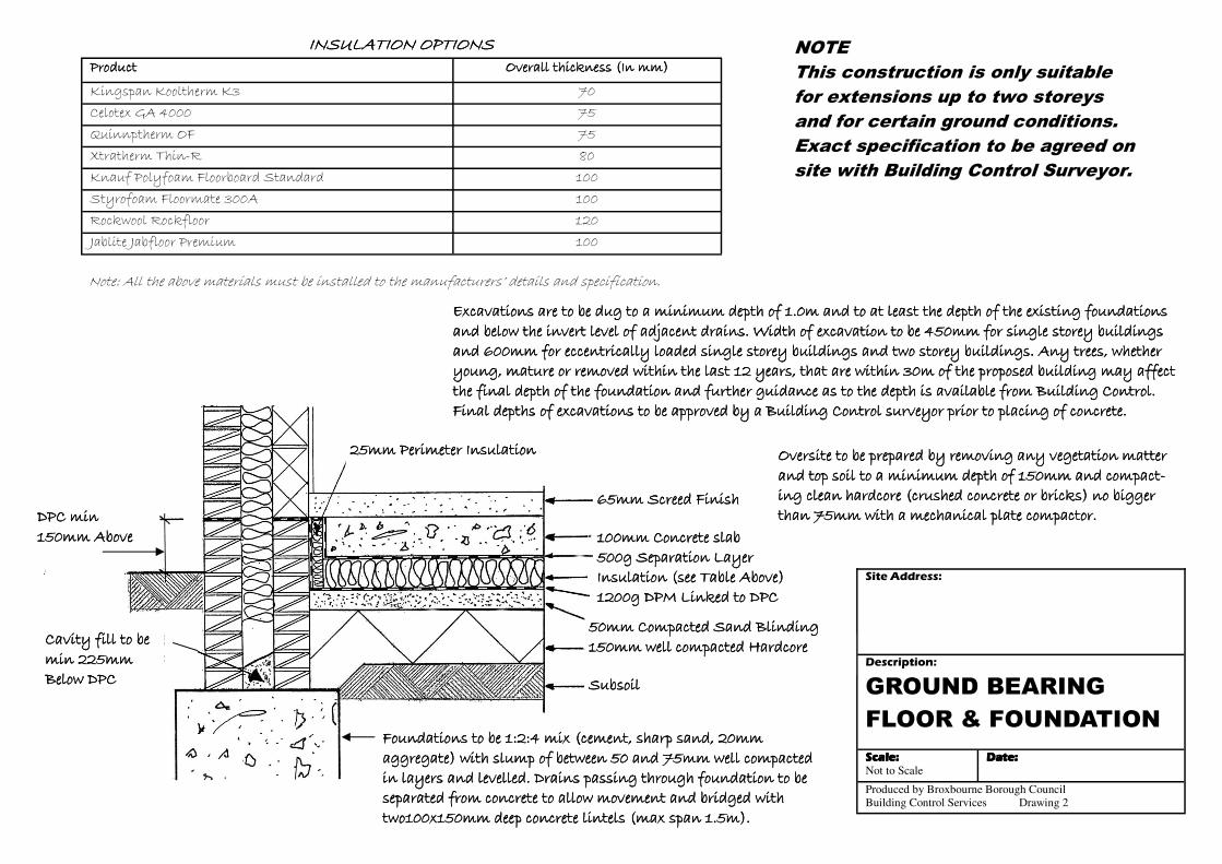
25mm Perimeter Insulation25mm Perimeter Insulation25mm Perimeter Insulation25mm Perimeter Insulation
50mm Compacted Sand Blinding50mm Compacted Sand Blinding50mm Compacted Sand Blinding50mm Compacted Sand Blinding 150mm well compacted Hardcore150mm well compacted Hardcore150mm well compacted Hardcore150mm well compacted Hardcore SubsoilSubsoilSubsoilSubsoil
65mm Screed Finish65mm Screed Finish65mm Screed Finish65mm Screed Finish 100mm Concrete slab100mm Concrete slab100mm Concrete slab100mm Concrete slab 500g Separation Layer500g Separation Layer500g Separation Layer500g Separation Layer Insulation (see Table Above)Insulation (see Table Above)Insulation (see Table Above)Insulation (see Table Above) 1200g DPM Linked to DPC1200g DPM Linked to DPC1200g DPM Linked to DPC1200g DPM Linked to DPC
Foundations to be 1:2:4 mix (cement, sharp sand, 20mm Foundations to be 1:2:4 mix (cement, sharp sand, 20mm Foundations to be 1:2:4 mix (cement, sharp sand, 20mm Foundations to be 1:2:4 mix (cement, sharp sand, 20mm aggregate) with slump of between 50 and 75mm well compacted aggregate) with slump of between 50 and 75mm well compacted aggregate) with slump of between 50 and 75mm well compacted aggregate) with slump of between 50 and 75mm well compacted in layers and levelled. Drains passing through foundation to be in layers and levelled. Drains passing through foundation to be in layers and levelled. Drains passing through foundation to be in layers and levelled. Drains passing through foundation to be separated from concrete to allow movement and bridged with separated from concrete to allow movement and bridged with separated from concrete to allow movement and bridged with separated from concrete to allow movement and bridged with two100x150mm deep concrete lintels (max span 1.5m).two100x150mm deep concrete lintels (max span 1.5m).two100x150mm deep concrete lintels (max span 1.5m).two100x150mm deep concrete lintels (max span 1.5m).
Excavations are to be dug to a minimum depth of 1.0m and to at least the depth of the existing foundations Excavations are to be dug to a minimum depth of 1.0m and to at least the depth of the existing foundations Excavations are to be dug to a minimum depth of 1.0m and to at least the depth of the existing foundations Excavations are to be dug to a minimum depth of 1.0m and to at least the depth of the existing foundations and below the invert level of adjacent drains. Width of excavation to be 450mm for single storey buildings and below the invert level of adjacent drains. Width of excavation to be 450mm for single storey buildings and below the invert level of adjacent drains. Width of excavation to be 450mm for single storey buildings and below the invert level of adjacent drains. Width of excavation to be 450mm for single storey buildings and 600mm for eccentrically loaded single storey buildings and two storey buildings. Any trees, whether and 600mm for eccentrically loaded single storey buildings and two storey buildings. Any trees, whether and 600mm for eccentrically loaded single storey buildings and two storey buildings. Any trees, whether and 600mm for eccentrically loaded single storey buildings and two storey buildings. Any trees, whether yyyyoooouuuunnnngggg,,,, mmmmaaaattttuuuurrrreeee oooorrrr rrrreeeemmmmoooovvvveeeedddd wwwwiiiitttthhhhiiiinnnn tttthhhheeee llllaaaasssstttt 11112222 yyyyeeeeaaaarrrrssss,,,, tttthhhhaaaatttt aaaarrrreeee wwwwiiiitttthhhhiiiinnnn 33330000mmmm ooooffff tttthhhheeee pppprrrrooooppppoooosssseeeedddd bbbbuuuuiiiillllddddiiiinnnngggg mmmmaaaayyyy aaaaffffffffeeeecccctttt the final depth of the foundation and further guidance as to the depth is available from Building Control. the final depth of the foundation and further guidance as to the depth is available from Building Control. the final depth of the foundation and further guidance as to the depth is available from Building Control. the final depth of the foundation and further guidance as to the depth is available from Building Control. Final depths of excavations to be approved by a Building Control surveyor prior to placing of concrete.Final depths of excavations to be approved by a Building Control surveyor prior to placing of concrete.Final depths of excavations to be approved by a Building Control surveyor prior to placing of concrete.Final depths of excavations to be approved by a Building Control surveyor prior to placing of concrete.
Oversite to be prepared by removing any vegetation matter Oversite to be prepared by removing any vegetation matter Oversite to be prepared by removing any vegetation matter Oversite to be prepared by removing any vegetation matter and top soil to a minimum depth of 150mm and compact-and top soil to a minimum depth of 150mm and compact-and top soil to a minimum depth of 150mm and compact-and top soil to a minimum depth of 150mm and compact-ing clean hardcore (crushed concrete or bricks) no bigger ing clean hardcore (crushed concrete or bricks) no bigger ing clean hardcore (crushed concrete or bricks) no bigger ing clean hardcore (crushed concrete or bricks) no bigger than 75mm with a mechanical plate compactor.than 75mm with a mechanical plate compactor.than 75mm with a mechanical plate compactor.than 75mm with a mechanical plate compactor.
INSULATION OPTIONSINSULATION OPTIONSINSULATION OPTIONSINSULATION OPTIONS NOTE
This construction is only suitable
for extensions up to two storeys
and for certain ground conditions.
Exact specification to be agreed on
site with Building Control Surveyor.
ProductProductProductProduct Overall thickness (In mm)Overall thickness (In mm)Overall thickness (In mm)Overall thickness (In mm)
Kingspan Kooltherm K3 70
Celotex GA 4000 75
Quinnptherm OF 75
Xtratherm Thin-R 80
Knauf Polyfoam Floorboard Standard 100
Styrofoam Floormate 300A 100
Rockwool Rockfloor 120
Jablite Jabfloor Premium 100
Note: All the above materials must be installed to the manufacturers’ details and specification.
Site Address:Site Address:Site Address:Site Address:
Description:
SUSPENDED TIMBER
FLOOR
Scale:Scale:Scale:Scale: Not to Scale
Date:Date:Date:Date:
Produced by Broxbourne Borough Council
Building Control Services Drawing 7
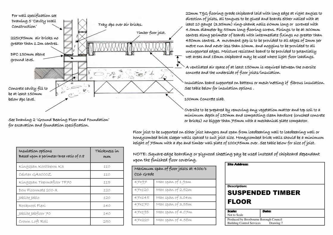
Maximum span of floor joists at 400c/c Maximum span of floor joists at 400c/c Maximum span of floor joists at 400c/c Maximum span of floor joists at 400c/c C16 GradeC16 GradeC16 GradeC16 Grade
47x97 Max span of 1.93m
47x120 Max span of 2.52m
47x145 Max span of 3.04m
47x220 Max span of 4.58m
47x170 Max span of 3.55m
47x195 Max span of 4.07m
Insulation optionsInsulation optionsInsulation optionsInsulation options Based upon a perimeter/area ratio of 0.8Based upon a perimeter/area ratio of 0.8Based upon a perimeter/area ratio of 0.8Based upon a perimeter/area ratio of 0.8
Thickness in Thickness in Thickness in Thickness in mmmmmmmm
Kingspan Kooltherm K3 110
Celotex GA3000Z 110
Kingspan Thermafloor TF70 115
Dow Floormate 200-X 120
Jablite Jablo 120
Rockwool Flexi 140
Jablite Jabfloor 70 140
Crown Loft Roll 250
22222222mmmmmmmm TTTT&&&&GGGG fffflllloooooooorrrriiiinnnngggg ggggrrrraaaaddddeeee cccchhhhiiiippppbbbbooooaaaarrrrdddd llllaaaaiiiidddd wwwwiiiitttthhhh lllloooonnnngggg eeeeddddggggeeee aaaatttt rrrriiiigggghhhhtttt aaaannnngggglllleeeessss ttttoooo direction of joists, all tongues to be glued and boards either nailed with at direction of joists, all tongues to be glued and boards either nailed with at direction of joists, all tongues to be glued and boards either nailed with at direction of joists, all tongues to be glued and boards either nailed with at least 10 gauge (3.35mm) ringleast 10 gauge (3.35mm) ringleast 10 gauge (3.35mm) ringleast 10 gauge (3.35mm) ring----shank nails 60mm long or screwed with shank nails 60mm long or screwed with shank nails 60mm long or screwed with shank nails 60mm long or screwed with 4444....5555mmmmmmmm ddddiiiiaaaammmmeeeetttteeeerrrr bbbbyyyy 55555555mmmmmmmm lllloooonnnngggg fffflllloooooooorrrriiiinnnngggg ssssccccrrrreeeewwwwssss.... FFFFiiiixxxxiiiinnnnggggssss ttttoooo bbbbeeee aaaatttt 333300000000mmmmmmmm cccceeeennnnttttrrrreeeessss aaaalllloooonnnngggg ppppeeeerrrriiiimmmmeeeetttteeeerrrr ooooffff bbbbooooaaaarrrrddddssss wwwwiiiitttthhhh iiiinnnntttteeeerrrrmmmmeeeeddddiiiiaaaatttteeee ffffiiiixxxxiiiinnnnggggssss nnnnoooo ggggrrrreeeeaaaatttteeeerrrr tttthhhhaaaannnn 444455550000mmmmmmmm cccceeeennnnttttrrrreeeessss.... AAAA mmmmoooovvvveeeemmmmeeeennnntttt ggggaaaapppp iiiissss ttttoooo bbbbeeee pppprrrroooovvvviiiiddddeeeedddd ttttoooo aaaallllllll eeeeddddggggeeeessss ooooffff 2222mmmmmmmm ppppeeeerrrr metre run and never less than 10mm. and noggins to be provided to all metre run and never less than 10mm. and noggins to be provided to all metre run and never less than 10mm. and noggins to be provided to all metre run and never less than 10mm. and noggins to be provided to all unsupported edges. Moisture resistant board to be provided to potentially unsupported edges. Moisture resistant board to be provided to potentially unsupported edges. Moisture resistant board to be provided to potentially unsupported edges. Moisture resistant board to be provided to potentially wet areas and 18mm chipboard may be used where light floor loadings.wet areas and 18mm chipboard may be used where light floor loadings.wet areas and 18mm chipboard may be used where light floor loadings.wet areas and 18mm chipboard may be used where light floor loadings.
A ventilated air space of at least 150mm is required between the oversite A ventilated air space of at least 150mm is required between the oversite A ventilated air space of at least 150mm is required between the oversite A ventilated air space of at least 150mm is required between the oversite concrete and the underside of floor joists/insulation. concrete and the underside of floor joists/insulation. concrete and the underside of floor joists/insulation. concrete and the underside of floor joists/insulation.
225x75mm air bricks no 225x75mm air bricks no 225x75mm air bricks no 225x75mm air bricks no greater than 1.2m centres. greater than 1.2m centres. greater than 1.2m centres. greater than 1.2m centres. DPC 150mm above DPC 150mm above DPC 150mm above DPC 150mm above ground level.ground level.ground level.ground level.
Tray dpc over air bricks.Tray dpc over air bricks.Tray dpc over air bricks.Tray dpc over air bricks.
IIIInnnnssssuuuullllaaaattttiiiioooonnnn bbbbooooaaaarrrrdddd ssssuuuuppppppppoooorrrrtttteeeedddd oooonnnn bbbbaaaatttttttteeeennnnssss oooorrrr mmmmeeeesssshhhh////nnnneeeettttttttiiiinnnngggg iiiiffff ffffiiiibbbbrrrroooouuuussss iiiinnnnssssuuuullllaaaattttiiiioooonnnn.... See table below for insulation options .See table below for insulation options .See table below for insulation options .See table below for insulation options . 100mm Concrete slab.100mm Concrete slab.100mm Concrete slab.100mm Concrete slab. OOOOvvvveeeerrrrssssiiiitttteeee ttttoooo bbbbeeee pppprrrreeeeppppaaaarrrreeeedddd bbbbyyyy rrrreeeemmmmoooovvvviiiinnnngggg aaaannnnyyyy vvvveeeeggggeeeettttaaaattttiiiioooonnnn mmmmaaaatttttttteeeerrrr aaaannnndddd ttttoooopppp ssssooooiiiillll ttttoooo aaaa mmmmiiiinnnniiiimmmmuuuummmm ddddeeeepppptttthhhh ooooffff 111155550000mmmmmmmm aaaannnndddd ccccoooommmmppppaaaaccccttttiiiinnnngggg cccclllleeeeaaaannnn hhhhaaaarrrrddddccccoooorrrreeee ((((ccccrrrruuuusssshhhheeeedddd ccccoooonnnnccccrrrreeeetttteeee or bricks) no bigger than 75mm with a mechanical plate compactor.or bricks) no bigger than 75mm with a mechanical plate compactor.or bricks) no bigger than 75mm with a mechanical plate compactor.or bricks) no bigger than 75mm with a mechanical plate compactor.
Floor joist to be supported on either joist hangers and span from loadbearing wall to loadbearing wall or Floor joist to be supported on either joist hangers and span from loadbearing wall to loadbearing wall or Floor joist to be supported on either joist hangers and span from loadbearing wall to loadbearing wall or Floor joist to be supported on either joist hangers and span from loadbearing wall to loadbearing wall or hhhhoooonnnneeeeyyyyccccoooommmmbbbbeeeedddd bbbbrrrriiiicccckkkk sssslllleeeeeeeeppppeeeerrrr wwwwaaaallllllllssss ssssppppaaaacccceeeedddd ttttoooo ssssuuuuiiiitttt jjjjooooiiiisssstttt ssssiiiizzzzeeee.... HHHHoooonnnneeeeyyyyccccoooommmmbbbbeeeedddd bbbbrrrriiiicccckkkk wwwwaaaallllllllssss sssshhhhoooouuuulllldddd bbbbeeee aaaa mmmmiiiinnnniiiimmmmuuuummmm height of 75mm with a dpc and timber wall plate of 100x75mm over. See table below for size of joist.height of 75mm with a dpc and timber wall plate of 100x75mm over. See table below for size of joist.height of 75mm with a dpc and timber wall plate of 100x75mm over. See table below for size of joist.height of 75mm with a dpc and timber wall plate of 100x75mm over. See table below for size of joist. NOTE: SquareNOTE: SquareNOTE: SquareNOTE: Square----edge boarding or plywood sheeting pay be used instead of chipboard dependant edge boarding or plywood sheeting pay be used instead of chipboard dependant edge boarding or plywood sheeting pay be used instead of chipboard dependant edge boarding or plywood sheeting pay be used instead of chipboard dependant upon the finished floor covering.upon the finished floor covering.upon the finished floor covering.upon the finished floor covering.
Concrete cavity fill to Concrete cavity fill to Concrete cavity fill to Concrete cavity fill to be at least 150mm be at least 150mm be at least 150mm be at least 150mm below dpc level. below dpc level. below dpc level. below dpc level.
See Drawing 2 ‘Ground Bearing Floor and Foundation’ See Drawing 2 ‘Ground Bearing Floor and Foundation’ See Drawing 2 ‘Ground Bearing Floor and Foundation’ See Drawing 2 ‘Ground Bearing Floor and Foundation’ for excavation and foundation specification. for excavation and foundation specification. for excavation and foundation specification. for excavation and foundation specification.
Timber floor joist.Timber floor joist.Timber floor joist.Timber floor joist.
For wall specification see For wall specification see For wall specification see For wall specification see Drawing 5 ‘Cavity Wall Drawing 5 ‘Cavity Wall Drawing 5 ‘Cavity Wall Drawing 5 ‘Cavity Wall Construction’Construction’Construction’Construction’
Site Address:Site Address:Site Address:Site Address:
Description:
CAVITY WALL
CONSTRUCTION
Scale:Scale:Scale:Scale: Not to Scale
Date:Date:Date:Date:
Produced by Broxbourne Borough Council
Building Control Services Drawing 5
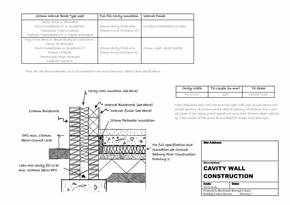
Note: Stainless steel wall ties must be used. Wall ties should have a hori-zontal spacing of 900mm and a vertical spacing of 225mm from verti-cal edges of the opening and spaced not more than 300mm apart vertical-ly. The number of ties must be increased at reveals and openings.
Cavity WidthCavity WidthCavity WidthCavity Width Tie Length (in mm)Tie Length (in mm)Tie Length (in mm)Tie Length (in mm) Tie ShapeTie ShapeTie ShapeTie Shape
76 to 100 225 Vertical twist
100mm Internal Block Type used100mm Internal Block Type used100mm Internal Block Type used100mm Internal Block Type used Full Fill Cavity InsulationFull Fill Cavity InsulationFull Fill Cavity InsulationFull Fill Cavity Insulation Internal FinishInternal FinishInternal FinishInternal Finish
Celcon Solar or Standard Durox Supablock 40 or Supablock
Thermalite Turbo or Shield Topblock Topblocklite GTI or Toplite Standard
95mm cavity filled with 85mm Crown Dritherm 37
12.5mm Plasterboard on dabs
Any of the above or denser blocks as listed below: Celcon Hi Strength
Durox Supablock4 or Supablock 7 Plasmor Fibolite
Thermalight High-Strength Topblock Toplite 7
95mm cavity filled with 85mm Crown Dritherm 32
15mm Light weight plaster
Note: All the above materials must be installed to the manufacturers’ details and specification.
DPC min. 150mm DPC min. 150mm DPC min. 150mm DPC min. 150mm above Ground Levelabove Ground Levelabove Ground Levelabove Ground Level
Lean mix cavity fill to be Lean mix cavity fill to be Lean mix cavity fill to be Lean mix cavity fill to be min. 225mm below DPCmin. 225mm below DPCmin. 225mm below DPCmin. 225mm below DPC
105mm Brickwork105mm Brickwork105mm Brickwork105mm Brickwork
Cavity Wall Insulation (see above)Cavity Wall Insulation (see above)Cavity Wall Insulation (see above)Cavity Wall Insulation (see above)
Internal Blockwork (see above)Internal Blockwork (see above)Internal Blockwork (see above)Internal Blockwork (see above)
25mm Perimeter insulation25mm Perimeter insulation25mm Perimeter insulation25mm Perimeter insulation
Internal finish (see above)Internal finish (see above)Internal finish (see above)Internal finish (see above)
For full specification and For full specification and For full specification and For full specification and Insulation see Ground Insulation see Ground Insulation see Ground Insulation see Ground Bearing Floor Construction Bearing Floor Construction Bearing Floor Construction Bearing Floor Construction Drawing 2.Drawing 2.Drawing 2.Drawing 2.
Site Address:Site Address:Site Address:Site Address:
Description:
SOLID WALL
CONSTRUCTION
Scale:Scale:Scale:Scale: Not to Scale
Date:Date:Date:Date:
Produced by Broxbourne Borough Council
Building Control Services Drawing 4
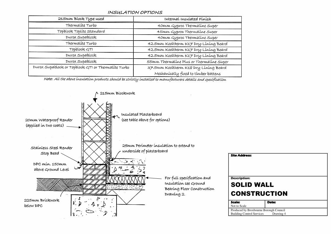
For full specification and For full specification and For full specification and For full specification and Insulation see Ground Insulation see Ground Insulation see Ground Insulation see Ground Bearing Floor Construction Bearing Floor Construction Bearing Floor Construction Bearing Floor Construction Drawing 2.Drawing 2.Drawing 2.Drawing 2.
25mm Perimeter insulation to extend to 25mm Perimeter insulation to extend to 25mm Perimeter insulation to extend to 25mm Perimeter insulation to extend to underside of plasterboardunderside of plasterboardunderside of plasterboardunderside of plasterboard
Insulated Plasterboard Insulated Plasterboard Insulated Plasterboard Insulated Plasterboard (see table above for options)(see table above for options)(see table above for options)(see table above for options)
215mm Blockwork215mm Blockwork215mm Blockwork215mm Blockwork
Stainless Steel Render Stainless Steel Render Stainless Steel Render Stainless Steel Render Stop BeadStop BeadStop BeadStop Bead
DPC min. 150mm DPC min. 150mm DPC min. 150mm DPC min. 150mm above Ground Levelabove Ground Levelabove Ground Levelabove Ground Level
20mm Waterproof Render 20mm Waterproof Render 20mm Waterproof Render 20mm Waterproof Render (applied in two coats)(applied in two coats)(applied in two coats)(applied in two coats)
225mm Brickwork 225mm Brickwork 225mm Brickwork 225mm Brickwork below DPCbelow DPCbelow DPCbelow DPC
Site Address:Site Address:Site Address:Site Address:
Description:
FLAT ROOF
CONSTRUCTION
Scale:Scale:Scale:Scale: Not to Scale
Date:Date:Date:Date:
Produced by Broxbourne Borough Council
Building Control Services Drawing 1
Site Address:Site Address:Site Address:Site Address:
Description:
FLAT ROOF
CONSTRUCTION
Scale:Scale:Scale:Scale: Not to Scale
Date:Date:Date:Date:
Produced by Broxbourne Borough Council
Building Control Services Drawing 1 Rev Sept2013
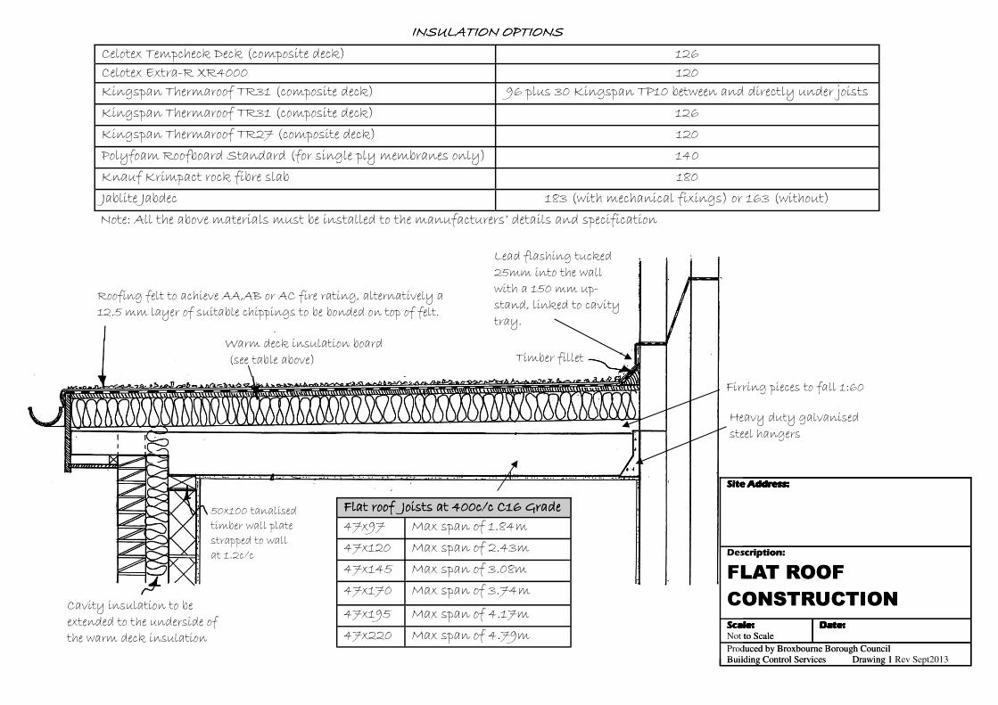
INSULATION OPTIONSINSULATION OPTIONSINSULATION OPTIONSINSULATION OPTIONS
Celotex Tempcheck Deck (composite deck) 126
Celotex Extra-R XR4000 120
Kingspan Thermaroof TR31 (composite deck) 96 plus 30 Kingspan TP10 between and directly under joists
Kingspan Thermaroof TR31 (composite deck) 126
Polyfoam Roofboard Standard (for single ply membranes only) 140
Knauf Krimpact rock fibre slab 180
Jablite Jabdec 183 (with mechanical fixings) or 163 (without)
Note: All the above materials must be installed to the manufacturers’ details and specification
Kingspan Thermaroof TR27 (composite deck) 120
Lead flashing tucked 25mm into the wall with a 150 mm up-stand, linked to cavity tray.
Timber fillet
50x100 tanalised timber wall plate strapped to wall at 1.2c/c
Roofing felt to achieve AA,AB or AC fire rating, alternatively a 12.5 mm layer of suitable chippings to be bonded on top of felt.
Warm deck insulation board (see table above)
Cavity insulation to be extended to the underside of the warm deck insulation
Heavy duty galvanised steel hangers
Firring pieces to fall 1:60
Flat roof Joists at 400c/c C16 GradeFlat roof Joists at 400c/c C16 GradeFlat roof Joists at 400c/c C16 GradeFlat roof Joists at 400c/c C16 Grade 47x97 Max span of 1.84m
47x120 Max span of 2.43m
47x145 Max span of 3.08m
47x170 Max span of 3.74m
47x195 Max span of 4.17m
47x220 Max span of 4.79m
Site Address:Site Address:Site Address:Site Address:
Description:
MONO-PITCHED ROOF
WITH FLAT CEILING
Scale:Scale:Scale:Scale: Not to Scale
Date:Date:Date:Date:
Produced by Broxbourne Borough Council
Building Control Services Drawing 6
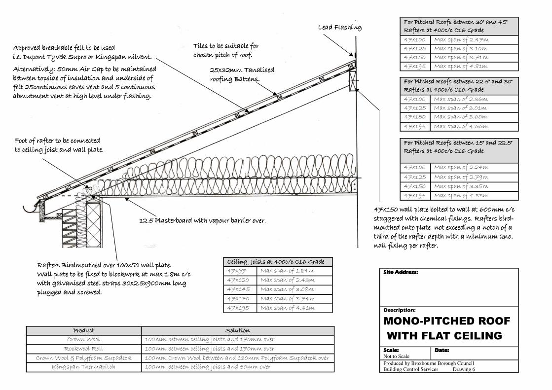
Rafters Birdmouthed over 100x50 wall plate.Rafters Birdmouthed over 100x50 wall plate.Rafters Birdmouthed over 100x50 wall plate.Rafters Birdmouthed over 100x50 wall plate. Wall plate to be fixed to blockwork at max 1.8m c/c Wall plate to be fixed to blockwork at max 1.8m c/c Wall plate to be fixed to blockwork at max 1.8m c/c Wall plate to be fixed to blockwork at max 1.8m c/c with galvanised steel straps 30x2.5x900mm long with galvanised steel straps 30x2.5x900mm long with galvanised steel straps 30x2.5x900mm long with galvanised steel straps 30x2.5x900mm long plugged and screwed. plugged and screwed. plugged and screwed. plugged and screwed.
47x150 wall plate bolted to wall at 600mm c/c 47x150 wall plate bolted to wall at 600mm c/c 47x150 wall plate bolted to wall at 600mm c/c 47x150 wall plate bolted to wall at 600mm c/c staggered with chemical fixings. Rafters bird-staggered with chemical fixings. Rafters bird-staggered with chemical fixings. Rafters bird-staggered with chemical fixings. Rafters bird-mouthed onto plate not exceeding a notch of a mouthed onto plate not exceeding a notch of a mouthed onto plate not exceeding a notch of a mouthed onto plate not exceeding a notch of a third of the rafter depth with a minimum 2no. third of the rafter depth with a minimum 2no. third of the rafter depth with a minimum 2no. third of the rafter depth with a minimum 2no. nail fixing per rafter.nail fixing per rafter.nail fixing per rafter.nail fixing per rafter.
ProductProductProductProduct SolutionSolutionSolutionSolution
Crown Wool 100mm between ceiling joists and 170mm over
Rockwool Roll 100mm between ceiling joists and 170mm over Crown Wool & Polyfoam Supadeck 100mm Crown Wool between and 130mm Polyfoam Supadeck over
Kingspan Thermapitch 100mm between ceiling joists and 50mm over
Ceiling Joists at 400c/c C16 GradeCeiling Joists at 400c/c C16 GradeCeiling Joists at 400c/c C16 GradeCeiling Joists at 400c/c C16 Grade 47x97 Max span of 1.84m
47x120 Max span of 2.43m
47x145 Max span of 3.08m
47x170 Max span of 3.74m
47x195 Max span of 4.41m
12.5 Plasterboard with vapour barrier over.12.5 Plasterboard with vapour barrier over.12.5 Plasterboard with vapour barrier over.12.5 Plasterboard with vapour barrier over.
Approved breathable felt to be used Approved breathable felt to be used Approved breathable felt to be used Approved breathable felt to be used i.e. Dupont Tyvek Supro or Kingspan nilvent.i.e. Dupont Tyvek Supro or Kingspan nilvent.i.e. Dupont Tyvek Supro or Kingspan nilvent.i.e. Dupont Tyvek Supro or Kingspan nilvent.
Alternatively: 50mm Air Gap to be maintained Alternatively: 50mm Air Gap to be maintained Alternatively: 50mm Air Gap to be maintained Alternatively: 50mm Air Gap to be maintained between topside of insulation and underside of between topside of insulation and underside of between topside of insulation and underside of between topside of insulation and underside of felt 25continuous eaves vent and 5 continuous felt 25continuous eaves vent and 5 continuous felt 25continuous eaves vent and 5 continuous felt 25continuous eaves vent and 5 continuous abmutment vent at high level under flashing.abmutment vent at high level under flashing.abmutment vent at high level under flashing.abmutment vent at high level under flashing.
Tiles to be suitable for Tiles to be suitable for Tiles to be suitable for Tiles to be suitable for chosen pitch of roof.chosen pitch of roof.chosen pitch of roof.chosen pitch of roof.
25x32mm Tanalised 25x32mm Tanalised 25x32mm Tanalised 25x32mm Tanalised roofing Battens.roofing Battens.roofing Battens.roofing Battens.
Lead FlashingLead FlashingLead FlashingLead Flashing
For Pitched Roofs between 22.5° and 30°For Pitched Roofs between 22.5° and 30°For Pitched Roofs between 22.5° and 30°For Pitched Roofs between 22.5° and 30° Rafters at 400c/c C16 GradeRafters at 400c/c C16 GradeRafters at 400c/c C16 GradeRafters at 400c/c C16 Grade
47x100 Max span of 2.36m
47x125 Max span of 3.01m
47x150 Max span of 3.60m
47x195 Max span of 4.66m
For Pitched Roofs between 15° and 22.5°For Pitched Roofs between 15° and 22.5°For Pitched Roofs between 15° and 22.5°For Pitched Roofs between 15° and 22.5° Rafters at 400c/c C16 GradeRafters at 400c/c C16 GradeRafters at 400c/c C16 GradeRafters at 400c/c C16 Grade
47x100 Max span of 2.24m
47x125 Max span of 2.79m
47x150 Max span of 3.35m
47x195 Max span of 4.33m
Foot of rafter to be connected Foot of rafter to be connected Foot of rafter to be connected Foot of rafter to be connected to ceiling joist and wall plate.to ceiling joist and wall plate.to ceiling joist and wall plate.to ceiling joist and wall plate.
For Pitched Roofs between 30° and 45°For Pitched Roofs between 30° and 45°For Pitched Roofs between 30° and 45°For Pitched Roofs between 30° and 45° Rafters at 400c/c C16 GradeRafters at 400c/c C16 GradeRafters at 400c/c C16 GradeRafters at 400c/c C16 Grade
47x100 Max span of 2.47m
47x125 Max span of 3.10m
47x150 Max span of 3.71m
47x195 Max span of 4.81m
Site Address:Site Address:Site Address:Site Address:
Description:
MONO-PITCHED ROOF
WITH VAULTED CEILING
Scale:Scale:Scale:Scale: Not to Scale
Date:Date:Date:Date:
Produced by Broxbourne Borough Council
Building Control Services Drawing 3
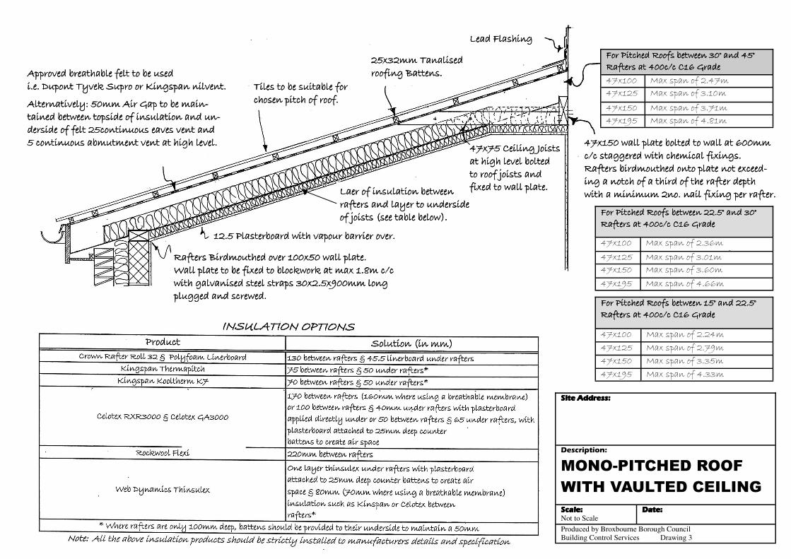
Lead FlashingLead FlashingLead FlashingLead Flashing
25x32mm Tanalised 25x32mm Tanalised 25x32mm Tanalised 25x32mm Tanalised roofing Battens.roofing Battens.roofing Battens.roofing Battens.
Tiles to be suitable for Tiles to be suitable for Tiles to be suitable for Tiles to be suitable for chosen pitch of roof.chosen pitch of roof.chosen pitch of roof.chosen pitch of roof.
Approved breathable felt to be used Approved breathable felt to be used Approved breathable felt to be used Approved breathable felt to be used i.e. Dupont Tyvek Supro or Kingspan nilvent.i.e. Dupont Tyvek Supro or Kingspan nilvent.i.e. Dupont Tyvek Supro or Kingspan nilvent.i.e. Dupont Tyvek Supro or Kingspan nilvent.
Alternatively: 50mm Air Gap to be main-Alternatively: 50mm Air Gap to be main-Alternatively: 50mm Air Gap to be main-Alternatively: 50mm Air Gap to be main-tained between topside of insulation and un-tained between topside of insulation and un-tained between topside of insulation and un-tained between topside of insulation and un-derside of felt 25continuous eaves vent and derside of felt 25continuous eaves vent and derside of felt 25continuous eaves vent and derside of felt 25continuous eaves vent and 5 continuous abmutment vent at high level.5 continuous abmutment vent at high level.5 continuous abmutment vent at high level.5 continuous abmutment vent at high level.
Rafters Birdmouthed over 100x50 wall plate.Rafters Birdmouthed over 100x50 wall plate.Rafters Birdmouthed over 100x50 wall plate.Rafters Birdmouthed over 100x50 wall plate. Wall plate to be fixed to blockwork at max 1.8m c/c Wall plate to be fixed to blockwork at max 1.8m c/c Wall plate to be fixed to blockwork at max 1.8m c/c Wall plate to be fixed to blockwork at max 1.8m c/c with galvanised steel straps 30x2.5x900mm long with galvanised steel straps 30x2.5x900mm long with galvanised steel straps 30x2.5x900mm long with galvanised steel straps 30x2.5x900mm long plugged and screwed. plugged and screwed. plugged and screwed. plugged and screwed.
12.5 Plasterboard with vapour barrier over.12.5 Plasterboard with vapour barrier over.12.5 Plasterboard with vapour barrier over.12.5 Plasterboard with vapour barrier over.
Laer of insulation between Laer of insulation between Laer of insulation between Laer of insulation between rafters and layer to underside rafters and layer to underside rafters and layer to underside rafters and layer to underside of joists (see table below).of joists (see table below).of joists (see table below).of joists (see table below).
47x75 Ceiling Joists 47x75 Ceiling Joists 47x75 Ceiling Joists 47x75 Ceiling Joists at high level bolted at high level bolted at high level bolted at high level bolted to roof joists and to roof joists and to roof joists and to roof joists and fixed to wall plate.fixed to wall plate.fixed to wall plate.fixed to wall plate.
44447777xxxx111155550000 wwwwaaaallllllll ppppllllaaaatttteeee bbbboooolllltttteeeedddd ttttoooo wwwwaaaallllllll aaaatttt 666600000000mmmmmmmm c/c staggered with chemical fixings. c/c staggered with chemical fixings. c/c staggered with chemical fixings. c/c staggered with chemical fixings. RRRRaaaafffftttteeeerrrrssss bbbbiiiirrrrddddmmmmoooouuuutttthhhheeeedddd oooonnnnttttoooo ppppllllaaaatttteeee nnnnooootttt eeeexxxxcccceeeeeeeedddd----ing a notch of a third of the rafter depth ing a notch of a third of the rafter depth ing a notch of a third of the rafter depth ing a notch of a third of the rafter depth wwwwiiiitttthhhh aaaa mmmmiiiinnnniiiimmmmuuuummmm 2222nnnnoooo.... nnnnaaaaiiiillll ffffiiiixxxxiiiinnnngggg ppppeeeerrrr rrrraaaafffftttteeeerrrr....
For Pitched Roofs between 30° and 45°For Pitched Roofs between 30° and 45°For Pitched Roofs between 30° and 45°For Pitched Roofs between 30° and 45° Rafters at 400c/c C16 GradeRafters at 400c/c C16 GradeRafters at 400c/c C16 GradeRafters at 400c/c C16 Grade
47x100 Max span of 2.47m
47x125 Max span of 3.10m
47x150 Max span of 3.71m
47x195 Max span of 4.81m
For Pitched Roofs between 22.5° and 30°For Pitched Roofs between 22.5° and 30°For Pitched Roofs between 22.5° and 30°For Pitched Roofs between 22.5° and 30° Rafters at 400c/c C16 GradeRafters at 400c/c C16 GradeRafters at 400c/c C16 GradeRafters at 400c/c C16 Grade
47x100 Max span of 2.36m
47x125 Max span of 3.01m
47x150 Max span of 3.60m
47x195 Max span of 4.66m
For Pitched Roofs between 15° and 22.5°For Pitched Roofs between 15° and 22.5°For Pitched Roofs between 15° and 22.5°For Pitched Roofs between 15° and 22.5° Rafters at 400c/c C16 GradeRafters at 400c/c C16 GradeRafters at 400c/c C16 GradeRafters at 400c/c C16 Grade
47x100 Max span of 2.24m
47x125 Max span of 2.79m
47x150 Max span of 3.35m
47x195 Max span of 4.33m
Site Address:Site Address:Site Address:Site Address:
Description:
PITCHED ROOF
CONSTRUCTION
Scale:Scale:Scale:Scale: Not to Scale
Date:Date:Date:Date:
Produced by Broxbourne Borough Council
Building Control Services Drawing 6
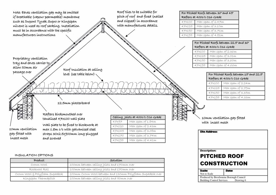
For Pitched Roofs between 30° and 45°For Pitched Roofs between 30° and 45°For Pitched Roofs between 30° and 45°For Pitched Roofs between 30° and 45° Rafters at 400c/c C16 GradeRafters at 400c/c C16 GradeRafters at 400c/c C16 GradeRafters at 400c/c C16 Grade
47x100 Max span of 2.47m
47x125 Max span of 3.10m
47x150 Max span of 3.71m
47x195 Max span of 4.81m
Ceiling Joists at 400c/c C16 GradeCeiling Joists at 400c/c C16 GradeCeiling Joists at 400c/c C16 GradeCeiling Joists at 400c/c C16 Grade 47x97 Max span of 1.84m
47x120 Max span of 2.43m
47x145 Max span of 3.08m
47x170 Max span of 3.74m
47x195 Max span of 4.41m
Roof Insulation at ceiling Roof Insulation at ceiling Roof Insulation at ceiling Roof Insulation at ceiling level (see table below)level (see table below)level (see table below)level (see table below)
Rafters birdsmouthed over Rafters birdsmouthed over Rafters birdsmouthed over Rafters birdsmouthed over tanalised 47x100 wall platetanalised 47x100 wall platetanalised 47x100 wall platetanalised 47x100 wall plate
Wall plate to be fixed to blockwork at Wall plate to be fixed to blockwork at Wall plate to be fixed to blockwork at Wall plate to be fixed to blockwork at max 1.8m c/c with galvanised steel max 1.8m c/c with galvanised steel max 1.8m c/c with galvanised steel max 1.8m c/c with galvanised steel straps 30x2.5x900mm long plugged straps 30x2.5x900mm long plugged straps 30x2.5x900mm long plugged straps 30x2.5x900mm long plugged and screwed and screwed and screwed and screwed
12.5mm plasterboard12.5mm plasterboard12.5mm plasterboard12.5mm plasterboard
Proprietary ventilation Proprietary ventilation Proprietary ventilation Proprietary ventilation tray and eaves carrier to tray and eaves carrier to tray and eaves carrier to tray and eaves carrier to allow 50mm air allow 50mm air allow 50mm air allow 50mm air passage overpassage overpassage overpassage over
For Pitched Roofs between 22.5° and 30°For Pitched Roofs between 22.5° and 30°For Pitched Roofs between 22.5° and 30°For Pitched Roofs between 22.5° and 30° Rafters at 400c/c C16 GradeRafters at 400c/c C16 GradeRafters at 400c/c C16 GradeRafters at 400c/c C16 Grade
47x100 Max span of 2.36m
47x125 Max span of 3.01m
47x150 Max span of 3.60m
47x195 Max span of 4.66m
For Pitched Roofs between 15° and 22.5°For Pitched Roofs between 15° and 22.5°For Pitched Roofs between 15° and 22.5°For Pitched Roofs between 15° and 22.5° Rafters at 400c/c C16 GradeRafters at 400c/c C16 GradeRafters at 400c/c C16 GradeRafters at 400c/c C16 Grade
47x100 Max span of 2.24m
47x125 Max span of 2.79m
47x150 Max span of 3.35m
47x195 Max span of 4.33m
10mm ventilation 10mm ventilation 10mm ventilation 10mm ventilation gap fitted withgap fitted withgap fitted withgap fitted with insect meshinsect meshinsect meshinsect mesh
10mm ventilation gap fitted 10mm ventilation gap fitted 10mm ventilation gap fitted 10mm ventilation gap fitted with insect meshwith insect meshwith insect meshwith insect mesh
Note: Eaves ventilation gap may be omitted Note: Eaves ventilation gap may be omitted Note: Eaves ventilation gap may be omitted Note: Eaves ventilation gap may be omitted if breathable (vapour pearmeable) membrane if breathable (vapour pearmeable) membrane if breathable (vapour pearmeable) membrane if breathable (vapour pearmeable) membrane such as Dupont Tyvek Supro or Kingspan such as Dupont Tyvek Supro or Kingspan such as Dupont Tyvek Supro or Kingspan such as Dupont Tyvek Supro or Kingspan nilvent is used as roof sarking. Installation nilvent is used as roof sarking. Installation nilvent is used as roof sarking. Installation nilvent is used as roof sarking. Installation must be in accordance with the specific must be in accordance with the specific must be in accordance with the specific must be in accordance with the specific manufacturers instructionsmanufacturers instructionsmanufacturers instructionsmanufacturers instructions
ProductProductProductProduct SolutionSolutionSolutionSolution
Crown Wool 100mm between ceiling joists and 170mm over Rockwool Roll 100mm between ceiling joists and 170mm over
Crown Wool & Polyfoam Supadeck 100mm Crown Wool between and 130mm Polyfoam Supadeck over Kingspan Thermapitch 100mm between ceiling joists and 50mm over
INSULATION OPTIONSINSULATION OPTIONSINSULATION OPTIONSINSULATION OPTIONS
Roof tiles to be suitable for Roof tiles to be suitable for Roof tiles to be suitable for Roof tiles to be suitable for pitch of roof and fixed (nailed pitch of roof and fixed (nailed pitch of roof and fixed (nailed pitch of roof and fixed (nailed and clipped) in accordance and clipped) in accordance and clipped) in accordance and clipped) in accordance with manufactures details.with manufactures details.with manufactures details.with manufactures details.
Site Address:Site Address:Site Address:Site Address:
Description:
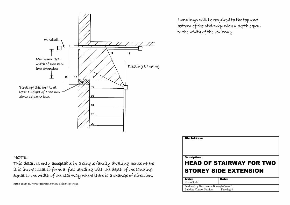
HEAD OF STAIRWAY FOR TWO
STOREY SIDE EXTENSION
Scale:Scale:Scale:Scale: Not to Scale
Date:Date:Date:Date:
Produced by Broxbourne Borough Council
Building Control Services Drawing 8
HandrailHandrailHandrailHandrail
Existing LandingExisting LandingExisting LandingExisting Landing
Minimum clear Minimum clear Minimum clear Minimum clear width of 600 mm width of 600 mm width of 600 mm width of 600 mm into extensioninto extensioninto extensioninto extension
Block off this area to at Block off this area to at Block off this area to at Block off this area to at least a height of 1100 mm least a height of 1100 mm least a height of 1100 mm least a height of 1100 mm above adjacent levelabove adjacent levelabove adjacent levelabove adjacent level
NOTE:NOTE:NOTE:NOTE: This detail is only acceptable in a single family dwelling house where This detail is only acceptable in a single family dwelling house where This detail is only acceptable in a single family dwelling house where This detail is only acceptable in a single family dwelling house where it is impractical to form a full landing with the depth of the landing it is impractical to form a full landing with the depth of the landing it is impractical to form a full landing with the depth of the landing it is impractical to form a full landing with the depth of the landing equal to the width of the stairway where there is a change of direction.equal to the width of the stairway where there is a change of direction.equal to the width of the stairway where there is a change of direction.equal to the width of the stairway where there is a change of direction. Detail based on Herts Technical Forum Guidance Note 2.Detail based on Herts Technical Forum Guidance Note 2.Detail based on Herts Technical Forum Guidance Note 2.Detail based on Herts Technical Forum Guidance Note 2.
Landings will be required to the top and Landings will be required to the top and Landings will be required to the top and Landings will be required to the top and bottom of the stairway with a depth equal bottom of the stairway with a depth equal bottom of the stairway with a depth equal bottom of the stairway with a depth equal to the width of the stairway.to the width of the stairway.to the width of the stairway.to the width of the stairway.
GENERAL SPECIFICATION FOR DOMESTIC EXTENSIONS.GENERAL SPECIFICATION FOR DOMESTIC EXTENSIONS.GENERAL SPECIFICATION FOR DOMESTIC EXTENSIONS.GENERAL SPECIFICATION FOR DOMESTIC EXTENSIONS. (To be used in conjunction with standard detail sheets)
Non load bearing wallsNon load bearing wallsNon load bearing wallsNon load bearing walls Where concrete blocks are to be used for non load bearing walls; the wall is to be 100mm thick constructed on a thickened concrete slab. Where timber studwork is to be used; they are to be constructed with 75x 50mm at 450mm centres with head and sole plates. To be finished with 12.5mm plasterboard and a skim finish. Foul drainageFoul drainageFoul drainageFoul drainage to be 100mm diameter UPVC, flexibly jointed and surrounded in 150mm pea shingle. New manholes are to be constructed in 225mm semi-engineering brickwork on 150mm concrete base. All sizes are to be determined on site and subject to size and invert level. The external cover is to be cast iron or pressed galvanised steel and internal cover to be double sealed bolt down type. Waste pipes are to be 32mm diameter for hand basins, 40mm for sinks, baths or showers with access points at changes of direction. These are to be increased to 50mm diameter for runs over 1.7m. All traps to be 75mm with a deep seal. Rainwater drainageRainwater drainageRainwater drainageRainwater drainage A drainage system is to be used to carry all rain water away from the surface (roof or paved area). All design of rain water goods are to be carried out in accordance with BS EN 12056. The gutters should be a 100mm half round section to a 63mm Rainwater pipe with a sharp edged outlet at one end. The gutter should be laid level. These should connect to existing drains or new man holes. Details are to be confirmed on site. SoakawaySoakawaySoakawaySoakaway Where a soakaway is to be used for an extension up to 20m2, it should have an internal capacity of 1m3 if the ground is permeable, be of hollow construction and not be within 5m of any buildings. Window glazingWindow glazingWindow glazingWindow glazing Where new glazing is installed whether UPVC or timber framed windows the window energy rating (WER) should be a band C or better. If U values are used they must achieve 1.6 W/m2K or better. Draught stripping is to be used on all opening elements. Door glazingDoor glazingDoor glazingDoor glazing For door glazing the U value is to be 1.8 W/m2K or better. Where more than 50% of a door is glazed the U value of the door is the average of the window U value and the non glazed part. Safety glazingSafety glazingSafety glazingSafety glazing Safety glazing only needs to be installed to BS6206 where there are critical locations. The critical locations are from 800mm down to the finished floor level on any internal or external walls and partitions. They are also from 1500mm down to the finished floor level on a door and side panels. Page 1 of 2
Flashings and upstandsFlashings and upstandsFlashings and upstandsFlashings and upstands For flashings and upstands only Code 4 lead is to be used for flashings and upstands in accordance with BSEN 12588 (formerly BS1178). A minimum upstand of 150mm is required for roofing which is to be linked to a cavity tray. Any other flashing or lead work that has been disturbed is to be reinstated in code 4 lead. All lead work is to be designed and constructed in accordance with BS6915. Windows andWindows andWindows andWindows and VentilationVentilationVentilationVentilation New rooms are required to have to be ventilation to 1/20th of the floor area with trickle ventilation of 8000mm2 per room. Where a new kitchen is to be provided an extractor fan should be installed at a rate of 60 l/s or 30 l/s from the extractor hood. Where a new bathroom is to be provided an extractor fan should be installed to extract 15 l/s with a 15 min overrun. Internal doors are to be under cut with a minimum of 10mm above the finished floor level. Fire escape windowsFire escape windowsFire escape windowsFire escape windows Each first floor habitable room and ground floor inner rooms are to be provided with an escape window with an unobstructed openable area of at least 0.33m² and at least 450mm high and 450mm wide, the bottom of the openable area should be between 800mm and 1100mm above floor level. Electrical worksElectrical worksElectrical worksElectrical works New electrical works to be installed, inspected and tested by an electrician registered under the Competent Person Scheme. A copy of the appropriate BS7671 installation and test certificate must be provided to Building Control before a completion certificate can be issued. Internal LightingInternal LightingInternal LightingInternal Lighting At least three out of four of all the light fittings in the main dwelling spaces (excluding infrequently accessed spaces such as storage spaces) are to be low energy light fittings with lamp efficacy greater than 45 lumens per circuit watt and a total output greater than 400 lamp lumens. External LightingExternal LightingExternal LightingExternal Lighting Either lamp capacity is no greater than 100 lamp-watts per light fitting and all lamps are automatically controlled so as to switch off after the area lit by the fitting becomes unoccu-pied and all lamps automatically controlled so as to switch off when daylight is sufficient OR; Lamp efficacy is greater than 45 lumens per circuit watt, and all lamps are automatically controlled so as to switch off when daylight is sufficient and light fittings are controllable manually. Smoke detectionSmoke detectionSmoke detectionSmoke detection Mains operated smoke alarms with battery back up are to be provided to the circulation areas in each storey of the dwelling complying with BS5839 Part 6. Gas WorksGas WorksGas WorksGas Works Any new boiler must have a SEDBUK 2005 efficiency of at least 90%, or 88% as rated by SEDBUK 2009. All gas work must be carried out by a registered Gas Safe engineer. Party Wall ActParty Wall ActParty Wall ActParty Wall Act Party Wall Notices may need to be served to the property’s adjoining owners if work is to be carried out on or adjacent to a boundary line. Contact must be made with a Party Wall Surveyor to clarify the need for a Party Wall Agreement. Should you require any clarification regarding this specification, please contact Broxbourne Building Control on 01992 785566Should you require any clarification regarding this specification, please contact Broxbourne Building Control on 01992 785566Should you require any clarification regarding this specification, please contact Broxbourne Building Control on 01992 785566Should you require any clarification regarding this specification, please contact Broxbourne Building Control on 01992 785566.... Page 2 of 2Page 2 of 2Page 2 of 2Page 2 of 2