INSULATION MONITORING RELAIS - La protection … MONITORING RELAIS for use in medical rooms...
40
October 2010 INSULATION MONITORING RELAIS for use in medical rooms www.contrel.it industrial applications www.microener.com
Transcript of INSULATION MONITORING RELAIS - La protection … MONITORING RELAIS for use in medical rooms...

October 2010
INSULATION MONITORING RELAIS
for use in medical rooms
www.contrel.it
industrial applications
www.microener.com

RI se rie sThe RI isolationmonitor series, are designed to permanently monitor the isolation to earth,in single and three phase networks with isolated neutral or withoutneutral (IT systems ) up to 1.000Vac and dc networks up to 1.000Vdc.In the isolated neutral systems, in case of first leakage to earth, the tripping ofthe protection is not required, but according with the IEC 61557.8Standard,the leakage should be signalled by optical and acoustic means.The device generates internally a measure signal,which is applied between the controlled circuit and earth.
HRI se rie sThe working principle of the isolationmonitor for use inmedical room is basedon applying a dc voltage or a codified signal, between the secondaryof the isolation transformer and the equipotential node of the installation,pointing out therefore, in a case of an earth leakage, the current flowing in the relayand its corresponding isolation resistance of the installation.
/ www.microener.com 49 rue de l'université – F93191 NOISY LE GRAND – Tel: +33 1 48 15 09 09/Fax: +33 1 43 05 08 24 / E-mail: [email protected]

indexSerie RI e HRIForeword 2
RRII Se rie s - FFOO RR IINNDDUUSSTTRRIIAALL AAPPPPLLIICC AATTIIOO NNSSINSULATION MONITORING
RI-F48 | RI-R48 | RI-R48N 4Insulation monitoring relay for networks 24 - 48 Vac/dc
RI-R11 | RI-R11D 6Insulation monitoring relay for networks 110 - 220 Vdc
RI-R15 9Insulation monitoring relay for networks 300 / 500 / 1000 Vdc
RI-F22 | RI-R22 | RI-R38 13Insulation monitoring relay for networks max 440 Vac
ARI-R100 16Adapters for networks up to 1000 Vac
RI-R60 18Insulation monitoring relay for networks max 760/1000 Vac
RI-SM 22Insulation monitoring relay for out-voltage systems
HHRRII Se rie s - FFOO RR MMEEDDIICC AALL UUSSEE AANNDD HHOO SSPPIITTAA LL AAPPPPLLIICC AATTIIOO NN 24INSULATION MONITORINGGeneral - Models - Accessories - Options (only for HRI-R40 and HRI-R40W)
HRI-R40 | HRI-R40W 25
HRI-R22t 29
HRI-R24 32Insulation monitoring relay for use in medical rooms
PR5 34 Remote repetition panels
EML 36Remote serial concentrator
PRODUCTS PAGE
4
6
9
13
16
20
22
25
29
32
34
36
/ www.microener.com 49 rue de l'université – F93191 NOISY LE GRAND – Tel: +33 1 48 15 09 09/Fax: +33 1 43 05 08 24 / E-mail: [email protected]
RI seriesINSULATION MONITORINGFOR ISOLATED NEUTRAL NETWORKS (IT)
2
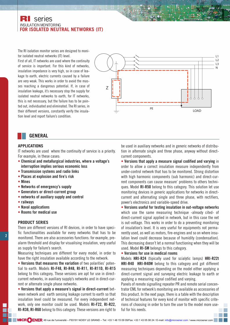
The RI isolation monitor series are designed to moni-tor isolated neutral networks (IT) level.First of all, IT networks are used where the continuityof service is important. For this kind of networks,insulation impedance is very high, so in case of lea-kage to earth, electric currents caused by a failureare very weak. This works in order to avoid the mas-ses reaching a dangerous potential. If, in case ofinsulation leakage, it’s necessary stop the supply forisolated neutral networks to earth, for IT networks,this is not necessary, but the failure has to be poin-ted out, individuated and eliminated. The RI series, intheir different versions, constantly verify the insula-tion level and report failure’s condition.
GENERAL
APPLICATIONSIT networks are used where the continuity of service is a priority.For example, in these cases:• Chemical and metallurgical industries, where a voltage’sinterruption implies serious economic loss
• Transmission systems and radio links• Places at explosion and fire’s risk• Mines• Networks of emergency’s supply• Generators or direct-current group• networks of auxiliary supply and control• railways• Naval applications• Rooms for medical use
PRODUCT SERIESThere are different versions of RI devices, in order to have speci-fic functionalities available for every networks that has to bemonitored. There are also accessories functions: for example, pre-alarm threshold and display for visualising insulation, very usefulas supply for failure’s search. Measuring techniques are different for every model, in order tohave the right insulation available according to the network.• Versions that measures the variation of two polarities’ poten-tial to earth. Models RI-F48, RI-R48, RI-R11, RI-R11D, RI-R15belong to this category. These versions are apt for use in direct-current networks, in auxiliary supply’s networks and in direct-cur-rent or alternate single phase networks.• Versions that apply a measure’s signal in direct-current bet-ween network and earth sensing leakage current to earth so thatinsulation level could be measured. For every independent net-work, only one monitor could be used. Models RI-F22, RI-R22,RI-R38, RI-R60 belong to this category. These versions are right to
be used in auxiliary networks and in generic networks of distribu-tion in alternate single and three phase, anyway without direct-current components.• Versions that apply a measure signal codified and varying inorder to allow a correct insulation measure independently fromunder-control network that has to be monitored. Strong distortionwith high harmonic components (sub harmonic) and direct-cur-rent components can cause measure’ problems to others techni-ques. Model RI-R50 belong to this category. This solution let usemonitoring devices in generic applications for networks in direct-current and alternating single and three phase, with rectifiers,power’s electronics and variable-speed drive.• Versions useful for testing insulation in out-voltage networkswhich use the same measuring technique -already cited- ofdirect-current signal applied in network, but in this case the netis out-voltage. This works in order to do a preventing monitoringof insulation’s level. It is very useful for equipments not perma-nently used, as well as motors, fire-engines and so on where insu-lation level could decrease because of humidity (condensation).This decreasing doesn’t let a normal functioning when they will beused. Model RI-SM belongs to this category.• Versions for use in medical roomsModels HRI-R24 (tipically used for scialytic lamps) HRI-R22tHRI-R40 HRI-R40W belong to this category and got differentmeasuring techniques depending on the model either applying adirect-current signal and surveying electric leakage to earth orapplying a measuring signal codified and varying.Panels of remote signalling repeater PR and remote serial concen-trator EML for network’s monitoring are available as accessories ofthis product. In the next page, there is a table with the descriptionof technical features for every kind of monitor with specific crite-rions of choosing in order to turn the user to the model more use-ful for his needs.
Z
LOADPE
L1L2L3N
/ www.microener.com 49 rue de l'université – F93191 NOISY LE GRAND – Tel: +33 1 48 15 09 09/Fax: +33 1 43 05 08 24 / E-mail: [email protected]

3
RI seriesINSULATION MONITORING
FOR ISOLATED NEUTRAL NETWORKS (IT)
FUNCTIONS TABLE
RI-R60 Alarm1 relais NO-C-NCFoult1 relais NO-C-NC
Local and remotemax 760 Vacmax 1000 Vacwith adapter ARI-R60
230 Vac115 Vac
Local and remoteAlarm faultinsulationlevel
dc signal
ARI-R100 Upper limit1000 Vacwith RI-R38
230 Vac115 Vac opt
RI-R15 Local polo +polo -
300 Vdc500 Vdc1.000 Vdcwith adapter ARI-R15
read fromunder controlnetwork
AutomaticManual localand remote
TRIP=30÷300 kohm Fault on +/LFault on -/NAlarm on +/LAlarm on -/N
Potential variationof polarities
1 relais NO-C-NCfail safe function
MODEL
RI-F48
NETWORKUNDER CONTROL
AUXILIARYSUPPLY
TRIPPINGTHRESHOLD
SIGNALS OUTPUT TEST RESET
1 relais NO-C-NC Local24 - 48 Vac/dc read fromunder controlnetwork
AutomaticTRIP 10 kohm fixed
Fault
MEASURAMENTTECHNOLOGY
Potential variationof polarities
RI-R48 1 relais NO-C-NC Local24 - 48 Vac/dc read fromunder controlnetwork
Manual localTRIP10 ÷ 50 kohm
FaultPotential variationof polarities
RI-R48N 1 relais NO-C-NC Local24 - 48 Vac/dc read fromunder controlnetwork
Manual localTRIP10 ÷ 60 kohm
Fault on +/LFault on -/N
Potential variationof polarities
RI-R11 110RI-R11 220
Local and remote80 ÷ 110 Vdc
185 ÷ 275 Vdcread fromunder controlnetwork
AutomaticManual localand remote
TRIP10 ÷ 100 kohmALARM30 ÷ 100 kohm
Fault on +/LFault on -/NAlarm on +/LAlarm on -/N
Potential variationof polarities
RI-R11D 110RI-R11D 220
Local and remote80 ÷ 110 Vdc
185 ÷ 275 Vdcread fromunder controlnetwork
AutomaticManual localand remote
TRIP10 ÷ 100 kohmALARM30 ÷ 100 kohm
Fault on +/LFault on -/NAlarm on +/LAlarm on -/NInsulation level(by LED bar)
Potential variationof polarities
RI-F22 1 relais NO-C-NC Localmax 230 Vacmax 500 Vac(with adapter)
230 Vac115 Vac opt
AutomaticTRIP100 kohm fixed
Faultdc signal
RI-R22 1 relais NO-C-NC Localmax 230 Vacmax 500 Vac(with adapter)
230 Vac115 Vac opt
Manual localand remote
TRIP25 ÷ 100 kohm
Faultdc signal
RI-R38 1 relais NO-C-NC Localmax 440 Vacmax 1000 Vac(with adapter)
115-230 Vac Manual localand remote
TRIP10 ÷ 100 kohm
Faultdc signal
- - -- --
RI-SM 1 relais NO-C-NC LocalOut of voltage read fromunder controlnetwork
AutomaticTRIP0.1 ÷ 10 Mohm
Faultdc signal
HRI-R24 1 relais NO-C-NC Local and remote,with appropriateremote panels
max 24 Vac read fromunder controlnetwork
Manual localTRIP10 ÷ 50 kohm
FaultPotential variationof polarities
HRI-R24t 1 relais NO-C-NC Local and remote,with appropriateremote panels
max 230 Vac 230 Vac115 Vac
Manual localTRIP50 ÷ 250 kohm
Fault forvisualizationinsulation levelby led bar
dc signal
HRI-R40 1 relais NO-C-NC Local and remote,with appropriateremote panels
max 230 Vac 230 Vac115 Vac
Manual localTRIP50 ÷ 500 kohm
Fault alarmdisplay 3 leddigit, min. valuememorized
dc signal
HRI-R40W 1 relais NO-C-NC Local and remote,with appropriateremote panels
max 230 Vac 230 Vac115 Vac
Manual localTRIP50 ÷ 500 kohm
Fault alarmdisplay 3 leddigit, min. valuememorized
Codified andvariable signal
Alarm2 relais NO-C-NCfail safe functionFault2 relais NO-C-NCfail safe functionAlarm2 relais NO-C-NCfail safe functionFault2 relais NO-C-NCfail safe function
/ www.microener.com 49 rue de l'université – F93191 NOISY LE GRAND – Tel: +33 1 48 15 09 09/Fax: +33 1 43 05 08 24 / E-mail: [email protected]
4
RI-F48 seriesRI-R48 seriesRI-R48N seriesINSULATION MONITORINGVERSIONS FOR NETWORKS ac/dc MAX 48 V
58
45
65
64 44
68
52,5
85,5
85
1 2 3 4 5 6
7 8 9
kΩ10203040
RI-R48NINSULATIONMONITOR
kΩ
10 11 12
contrelALARM
ON
_TEST
RESET
60 +TRIP
10
20
3040
50 ONTRIP TEST
RESET
INSULATIONMONITORINGRI-R48
kΩ
52,5
GENERAL
RI-F48 RI-R48 RI-R48N
1 2 3 4 5 6
7 8 9
kΩ10203040
RI-R48NINSULATIONMONITOR
kΩ
10 11 12
ALARM
ON
_TEST
RESET
60 +TRIP
10
20
3040
50 ONTRIP TEST
RESET
INSULATIONMONITORINGRI-R48
kΩ
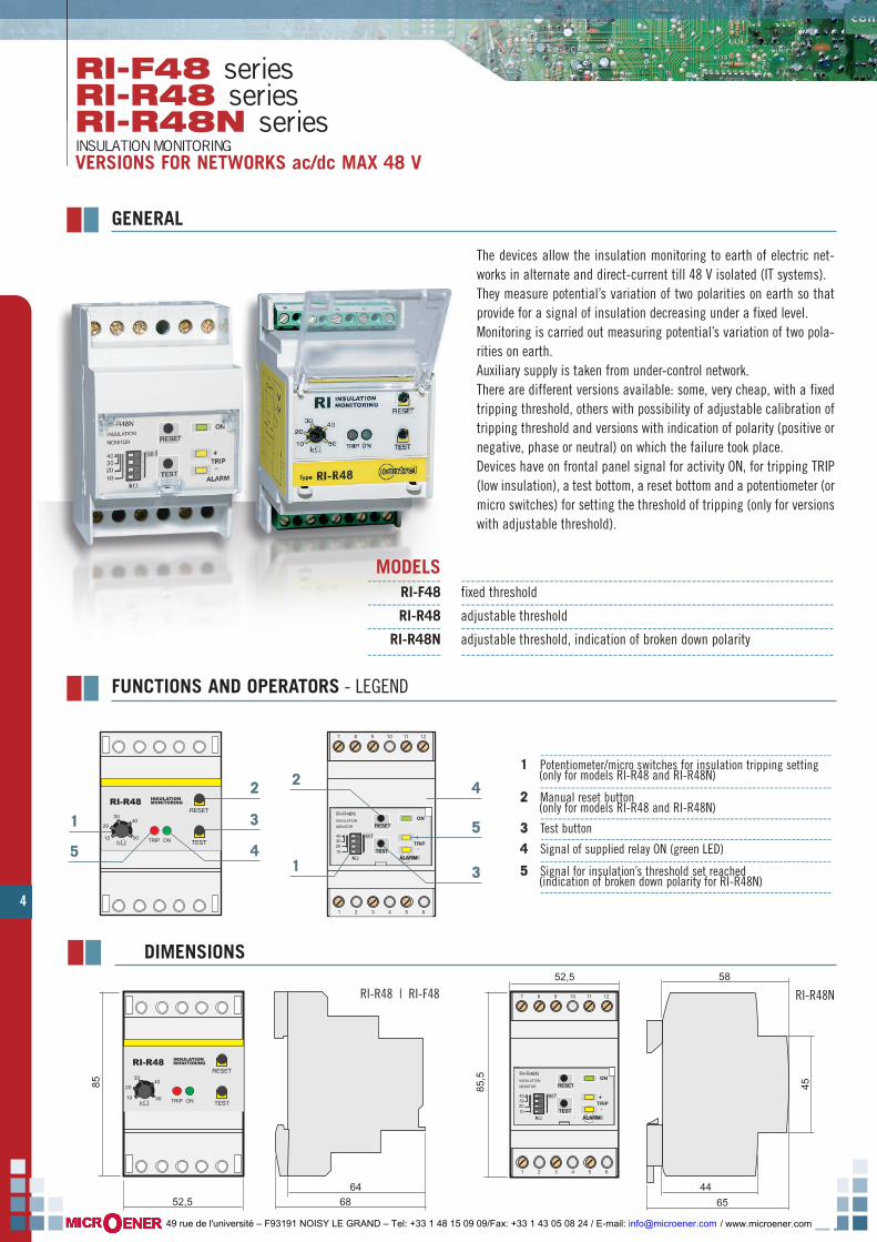
------------------------------------------------------------------11 Potentiometer/micro switches for insulation tripping setting
(only for models RI-R48 and RI-R48N)------------------------------------------------------------------
22 Manual reset button(only for models RI-R48 and RI-R48N)------------------------------------------------------------------
33 Test button------------------------------------------------------------------
44 Signal of supplied relay ON (green LED)------------------------------------------------------------------
55 Signal for insulation’s threshold set reached(indication of broken down polarity for RI-R48N)------------------------------------------------------------------
RI-R48 | RI-F48 RI-R48N
FUNCTIONS AND OPERATORS - LEGEND
22
33
44
11
55
RI-F48 RI-R48 RI-R48N
1 2 3 4 5 6
7 8 9
kΩ10203040
RI-R48NINSULATIONMONITOR
kΩ
10 11 12
contrelALARM
ON
_TEST
RESET
60 +TRIP
10
20
3040
50 ONTRIP TEST
RESET
INSULATIONMONITORINGRI-R48
kΩ
44
55
33
22
11
The devices allow the insulation monitoring to earth of electric net-works in alternate and direct-current till 48 V isolated (IT systems).They measure potential’s variation of two polarities on earth so thatprovide for a signal of insulation decreasing under a fixed level.Monitoring is carried out measuring potential’s variation of two pola-rities on earth.Auxiliary supply is taken from under-control network. There are different versions available: some, very cheap, with a fixedtripping threshold, others with possibility of adjustable calibration oftripping threshold and versions with indication of polarity (positive ornegative, phase or neutral) on which the failure took place.Devices have on frontal panel signal for activity ON, for tripping TRIP(low insulation), a test bottom, a reset bottom and a potentiometer (ormicro switches) for setting the threshold of tripping (only for versionswith adjustable threshold).
MODELS--------------- ----------------------------------------------------------------------------
RI-F48 fixed threshold--------------- ----------------------------------------------------------------------------
RI-R48 adjustable threshold--------------- ----------------------------------------------------------------------------
RI-R48N adjustable threshold, indication of broken down polarity--------------- ----------------------------------------------------------------------------
DIMENSIONS
/ www.microener.com 49 rue de l'université – F93191 NOISY LE GRAND – Tel: +33 1 48 15 09 09/Fax: +33 1 43 05 08 24 / E-mail: [email protected]
5
RI-F48 seriesRI-R48 series
RI-R48N seriesINSULATION MONITORING
VERSIONS FOR NETWORK ac/dc MAX 48 V
Auxiliary supply voltage 24 V or 48 V 50-60 Hz ± 20 % or dc ± 20 %Self-consumption 3 VA MAX Network voltage
24 V MAXMeasuring voltage0.5 mA MAXMeasuring current
100 kohmInternal impedanceRI-R48 adjustable 10 ÷ 50 kohm by potentiometerRI-R48N adjustable 10 ÷ 60 kohm by micro switchesRI-F48 fixed 10 kohm
Tripping threshold
about 1 secondTripping late
led ON - led TRIPbuttons TEST and RESET (only model RI-R48 / RI-R48N)
Signalling and operators
- 10 …+ 60 °CWorking temperature
- 20 …+ 70 °CStoring temperature< 90 %Relative humidity
Insulation testindifferentAssembling positionby screw terminals - wire section MAX 4 mm2Connection typeIP 40 frontal with cap - IP 20 caseProtection's degreeeasy connection snap on DIN rail 35 mm / 3 modules of 17.5 mmMounting according with DIN 50022approximately 300 gWeightCEI-EN 61010-1 / CEI-EN 61557-8 / VDE0413 part.8 / CEI-EN 61326-1Standard reference
24 ÷ 48 Vac/dc +10 %
relay switch contact NO-C-NC MAX 5 A 250 VacOutput
3 kV 60 sec / 4 kv imp. 1,2 / 50 µs
ELECTRIC CHARACTERISTICS
1 2 3 4 5 6 7 8 9PE
10
RI-F48 / RI-R48 / RI-R48N
AUX1
INSULATED LINE max 48Vac/dc
LOAD
OUT-NOOUT-NCRESET TEST RESETOUT-CAUX2
Vaux
PE
+
_
WIRING DIAGRAMS - LEGEND
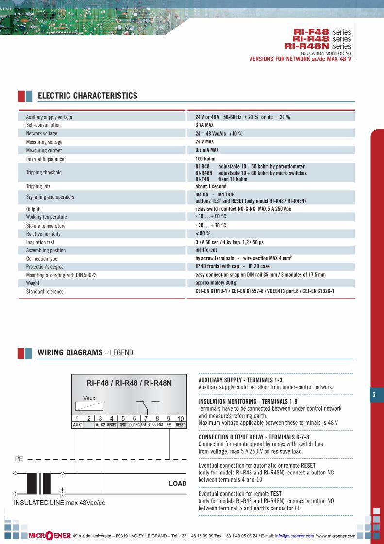
------------------------------------------------------------------------AUXILIARY SUPPLY - TERMINALS 1-3Auxiliary supply could be taken from under-control network.------------------------------------------------------------------------INSULATION MONITORING - TERMINALS 1-9Terminals have to be connected between under-control networkand measure’s referring earth.Maximum voltage applicable between these terminals is 48 V------------------------------------------------------------------------CONNECTION OUTPUT RELAY - TERMINALS 6-7-8Connection for remote signal by relays with switch freefrom voltage, max 5 A 250 V on resistive load.------------------------------------------------------------------------Eventual connection for automatic or remote RESET(only for models RI-R48 and RI-R48N), connect a button NCbetween terminals 4 and 10.------------------------------------------------------------------------Eventual connection for remote TEST(only for models RI-R48 and RI-R48N), connect a button NObetween terminal 5 and earth’s conductor PE------------------------------------------------------------------------
/ www.microener.com 49 rue de l'université – F93191 NOISY LE GRAND – Tel: +33 1 48 15 09 09/Fax: +33 1 43 05 08 24 / E-mail: [email protected]

RI-R11 seriesRI-R11D seriesINSULATION MONITORINGVERSIONS FOR NETWORKS dc MAX 250 V
6
The devices allow permanent monitoring of insulation of electricalnetworks in direct-current current isolated on earth (IT networks).Monitoring is carried out measuring potential’s variation of two pola-rities of network on earth. Auxiliary supply is taken from under-controlnetwork.These devices have two trip thresholds, which are adjustable by fron-tal micro switches, called ALARM and TRIP. This works in order tosignal that insulation’s level decreased under the threshold. Trip issignalled by frontal LED with indication of polarity (+ or -) that showlow insulation. Remote trip threshold is carried out by double switchtwo relays with contacts voltage-free. Relays could be programmed inpositive safe too (FAIL-SAFE function, normally excited). On the front,there are TEST and RESET buttons; test could be activated locally orby an external button; push button could be set manually or automa-tically, either with local button or with external push button.Model RI-R11D has a monitor of insulation’s level of the device by abar.
GENERAL
kΩTEST
RESET
300 100
offman
F.S. onauto
RESET
10204060
5030
80150
kΩTRIPALARM
offman
F.S. onauto
RESET
ALARM
TRIP
ON
+-
kΩ
connttrreellcontrel
Insulation monitor RI-B32
28 29 30 31 32 33 34 35 36
1 2 3 4 5 6 7 8 9 10 11 12 13 14 15 16 17 18
19 20 21 22 23 24 25 26 27
kΩTEST
RESET
300 100
offman
F.S. onauto
RESET
10204060
5030
80150
kΩTRIPALARM
offman
F.S. onauto
RESET
ALARM
TRIP
ON
+-
kΩ
connttrreellcontrel
Insulation monitor RI-R11
28 29 30 31 32 33 34 35 36
1 2 3 4 5 6 7 8 9 10 11 12 13 14 15 16 17 18
19 20 21 22 23 24 25 26 27
kΩTEST
RESET
300 100
offman
F.S. onauto
RESET
10204060
5030
80150
kΩTRIPALARM
offman
F.S. onauto
RESET
ALARM
TRIP
ON
+-
kΩ
contrelcontrel
Insulation monitor RI-B32
28 29 30 31 32 33 34 35 36
1 2 3 4 5 6 7 8 9 10 11 12 13 14 15 16 17 18
19 20 21 22 23 24 25 26 27
kΩTEST
RESET
300 100
offman
F.S. onauto
RESET
10204060
5030
80150
kΩTRIPALARM
offman
F.S. onauto
RESET
ALARM
TRIP
ON
+-
kΩ
contrelcontrel
Insulation monitor RI-B32
28 29 30 31 32 33 34 35 36
1 2 3 4 5 6 7 8 9 10 11 12 13 14 15 16 17 18
19 20 21 22 23 24 25 26 27
kΩTEST
RESET
300 100
offman
F.S. onauto
RESET
10204060
5030
80150
kΩTRIPALARM
offman
F.S. onauto
RESET
kΩ
ccoonnttrreellcontrel
Insulation monitor relay RI-R11D 5
10
20
50
100
200
400
600
kΩ
kΩ
kΩ
kΩ
kΩ
kΩ
kΩ
kΩ
total
trip
alarm
on
on
on
HOLD
TRIP
ALARM
ON
+
-
TEST
RESET
300
offman
TEST
RESET
300
offman
TEST
RESET
300
offman
TEST
RESET
300
offman
22
33
1155
44
66
77
99
---------------------------------------------------------------------------------------------------------------------------------------------------- 11 RESET button. This works only if RESET functioning is set manually.
---------------------------------------------------------------------------------------------------------------------------------------------------- 22 TEST button. Pushing TEST button cause either alarm activation or trip activation with output relays’ switching.
---------------------------------------------------------------------------------------------------------------------------------------------------- 33 LED ON for active device signalling
---------------------------------------------------------------------------------------------------------------------------------------------------- 44 LED TRIP for trip threshold TRIP signalling
---------------------------------------------------------------------------------------------------------------------------------------------------- 55 LED ALARM for alarm threshold ALARM signalling
---------------------------------------------------------------------------------------------------------------------------------------------------- 66 LED+ and LED- signalling which under-control network’s polarity has low insulation. Ignition of one of these LED will be connected
with ALARM LED and TRIP ignition. ----------------------------------------------------------------------------------------------------------------------------------------------------
77 Screw terminals for connections----------------------------------------------------------------------------------------------------------------------------------------------------
88 Micro switches for alarm threshold setting----------------------------------------------------------------------------------------------------------------------------------------------------
99 Micro switches for trip threshold setting----------------------------------------------------------------------------------------------------------------------------------------------------
1100 Led bar for insulation level visualising (only for RI-R11D)----------------------------------------------------------------------------------------------------------------------------------------------------
FUNCTIONS AND OPERATORS - LEGEND
88
22
33
1155
44
66
77
99
1100
88
MODELS------------------- --------------------------------------------------------------------------------------RI-R11 110 V Main supply and auxiliary voltage 110 Vdc / -15% +25% (80 ÷ 180 Vdc)RI-R11D 110 V Main supply and auxiliary voltage 110 Vdc / -15% +25% (80 ÷ 180 Vdc)------------------- --------------------------------------------------------------------------------------RI-R11 220 V Main supply and auxiliary voltage 220 Vdc /-15% +25% (185 ÷ 275 Vdc)
------------------- --------------------------------------------------------------------------------------
/ www.microener.com 49 rue de l'université – F93191 NOISY LE GRAND – Tel: +33 1 48 15 09 09/Fax: +33 1 43 05 08 24 / E-mail: [email protected]

7
RI-R11 seriesRI-R11D series
INSULATION MONITORINGVERSIONS FOR NETWORKS dc MAX 250 V
Network voltage and auxiliary supplyRI-R11 110 V 110 Vdc -15/+25 % (80 ÷ 180 Vdc)RI-R11D 110 V 110 Vdc -15/+25 % (80 ÷ 180 Vdc)RI-R11 220 V 220 Vdc -15/+25 % (185 ÷ 275 Vdc)
Self-consumption 5 W MAXAlternating residual load
300 ÷ 30 kohm (5 levels adjustable by micro switches)ALARM threshold setting
100 ÷ 10 kohm (5 levels adjustable by micro switches)TRIP threshold setting
led ON, led ALARM, led TRIP, led +, led -signalling insulation led bar (only for RI-R11D)
Signalling
about 1 secondTripping delayMAX 1.8 mAMeasure's currentRI-R11 / RI-R11D 110 V 200 kohm L+/L- 100 kohm L/earthRI-R11 220 V 400 kohm L+/L- 200 kohm L/earth
Internal impedance
ALARM : 2 contacts switched NO-C-NCTRIP : 2 contacts switched NO-C-NC
Output relay free from voltage contacts
5 A 250 Vac – 0.3 A 130 Vdc – 0.2 A 280 Vdc resistive load0.15 A 130 Vdc – 0.05 A 280 Vdc inductive load L/R < 40 mswith 2 serial contacts: 0.7 A 130 Vdc – 0.5 A 280 Vdc resistive load
Capacity relay contacts
output alarm function - fail safe function for both outputsmanual or automatic reset (external reset)Adjustable functions
- 10 …+ 60 °CWorking temperature- 20 …+ 70 °CStoring temperature< 90 %Relative humidity
Insulation testindifferentAssembling positionby screw terminals - wire section MAX 2.5 mm2Connection type
IP 40 frontal with cap - IP 20 caseProtection's degreeeasy connection snap on DIN rail 35 mm / 6 modules of 17.5 mmMounting according with DIN 50022
approximately 400 gWeightCEI-EN 61010-1 / CEI-EN 61557-8 / VDE 0413 part.8 / CEI-EN 61326-1Standard reference
5 %
ELECTRIC CHARACTERISTICS
DIMENSIONS
73
68
44
54
105
90 90
105
kΩTEST
RESET
300 100
offman
F.S. onauto
RESET
10204060
5030
80150
kΩTRIPALARM
offman
F.S. onauto
RESET
ALARM
TRIP
ON
+-
kΩ
connttrreellcontrel
Insulation monitor RI-B32
28 29 30 31 32 33 34 35 36
1 2 3 4 5 6 7 8 9 10 11 12 13 14 15 16 17 18
19 20 21 22 23 24 25 26 27
kΩTEST
RESET
300 100
offman
F.S. onauto
RESET
10204060
5030
80150
kΩTRIPALARM
offman
F.S. onauto
RESET
ALARM
TRIP
ON
+-
kΩ
connttrreellcontrel
Insulation monitor RI-R11
28 29 30 31 32 33 34 35 36
1 2 3 4 5 6 7 8 9 10 11 12 13 14 15 16 17 18
19 20 21 22 23 24 25 26 27
kΩTEST
RESET
300 100
offman
F.S. onauto
RESET
10204060
5030
80150
kΩTRIPALARM
offman
F.S. onauto
RESET
ALARM
TRIP
ON
+-
kΩ
contrelcontrel
Insulation monitor RI-B32
28 29 30 31 32 33 34 35 36
1 2 3 4 5 6 7 8 9 10 11 12 13 14 15 16 17 18
19 20 21 22 23 24 25 26 27
kΩTEST
RESET
300 100
offman
F.S. onauto
RESET
10204060
5030
80150
kΩTRIPALARM
offman
F.S. onauto
RESET
ALARM
TRIP
ON
+-
kΩ
contrelcontrel
Insulation monitor RI-B32
28 29 30 31 32 33 34 35 36
1 2 3 4 5 6 7 8 9 10 11 12 13 14 15 16 17 18
19 20 21 22 23 24 25 26 27
kΩTEST
RESET
300 100
offman
F.S. onauto
RESET
10204060
5030
80150
kΩTRIPALARM
offman
F.S. onauto
RESET
kΩ
ccoonnttrreellcontrel
Insulation monitor relay RI-R11D 5
10
20
50
100
200
400
600
kΩ
kΩ
kΩ
kΩ
kΩ
kΩ
kΩ
kΩ
total
trip
alarm
on
on
on
HOLD
TRIP
ALARM
ON
+
-
TEST
RESET
300
offman
TEST
RESET
300
offman
TEST
RESET
300
offman
TEST
RESET
300
offman
RI-R11 RI-R11D
/ www.microener.com 49 rue de l'université – F93191 NOISY LE GRAND – Tel: +33 1 48 15 09 09/Fax: +33 1 43 05 08 24 / E-mail: [email protected]
8
RI-R11 seriesRI-R11D seriesINSULATION MONITORINGVERSIONS FOR NETWORKS dc MAX 250 V
WIRING DIAGRAMS - LEGENDA
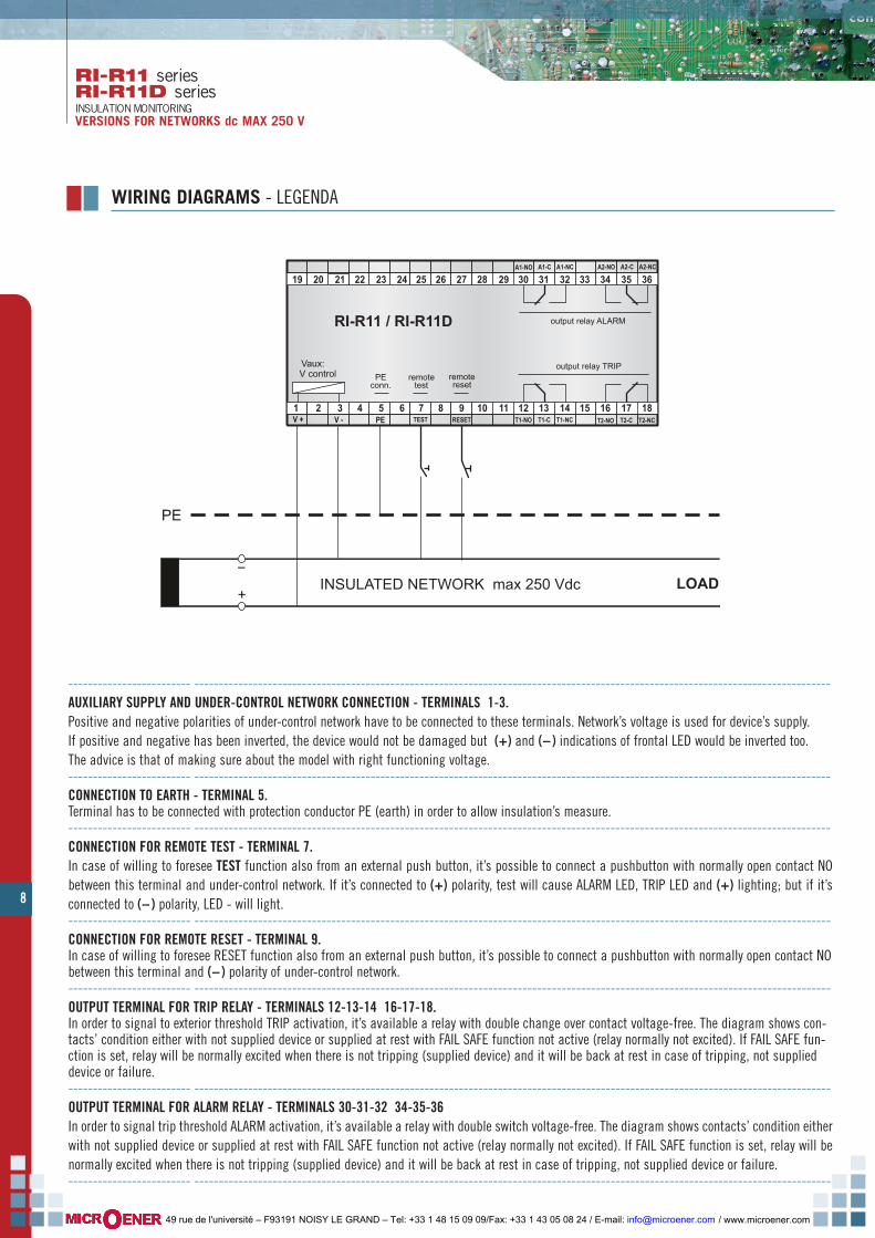
------------------------- ----------------------------------------------------------------------------------------------------------------------------------AUXILIARY SUPPLY AND UNDER-CONTROL NETWORK CONNECTION - TERMINALS 1-3.Positive and negative polarities of under-control network have to be connected to these terminals. Network’s voltage is used for device’s supply.If positive and negative has been inverted, the device would not be damaged but (+) and (-- ) indications of frontal LED would be inverted too. The advice is that of making sure about the model with right functioning voltage.------------------------- ----------------------------------------------------------------------------------------------------------------------------------CONNECTION TO EARTH - TERMINAL 5.Terminal has to be connected with protection conductor PE (earth) in order to allow insulation’s measure.------------------------- ----------------------------------------------------------------------------------------------------------------------------------CONNECTION FOR REMOTE TEST - TERMINAL 7.In case of willing to foresee TEST function also from an external push button, it’s possible to connect a pushbutton with normally open contact NObetween this terminal and under-control network. If it’s connected to (+) polarity, test will cause ALARM LED, TRIP LED and (+) lighting; but if it’sconnected to (-- ) polarity, LED - will light.------------------------- ----------------------------------------------------------------------------------------------------------------------------------CONNECTION FOR REMOTE RESET - TERMINAL 9.In case of willing to foresee RESET function also from an external push button, it’s possible to connect a pushbutton with normally open contact NObetween this terminal and (-- ) polarity of under-control network.------------------------- ----------------------------------------------------------------------------------------------------------------------------------OUTPUT TERMINAL FOR TRIP RELAY - TERMINALS 12-13-14 16-17-18.In order to signal to exterior threshold TRIP activation, it’s available a relay with double change over contact voltage-free. The diagram shows con-tacts’ condition either with not supplied device or supplied at rest with FAIL SAFE function not active (relay normally not excited). If FAIL SAFE fun-ction is set, relay will be normally excited when there is not tripping (supplied device) and it will be back at rest in case of tripping, not supplieddevice or failure.------------------------- ----------------------------------------------------------------------------------------------------------------------------------OUTPUT TERMINAL FOR ALARM RELAY - TERMINALS 30-31-32 34-35-36In order to signal trip threshold ALARM activation, it’s available a relay with double switch voltage-free. The diagram shows contacts’ condition eitherwith not supplied device or supplied at rest with FAIL SAFE function not active (relay normally not excited). If FAIL SAFE function is set, relay will benormally excited when there is not tripping (supplied device) and it will be back at rest in case of tripping, not supplied device or failure.------------------------- ----------------------------------------------------------------------------------------------------------------------------------
PEV + TEST
Vaux:V control remote
reset
A2-NO A2-C A2-NC
RI-R11 / RI-R11D
V - RESET
A1-NO A1-C A1-NC
T1-NO T1-C T1-NC T2-NO T2-C T2-NC
output relay TRIP
output relay ALARM
remotetest
PEconn.
INSULATED NETWORK max 250 Vdc LOAD+
_
PE
1 2 3 4 5 6 7 8 9 10 11 12 13 14 15 16 17 18
19 20 21 22 23 24 25 26 27 28 29 30 31 32 33 34 35 36
/ www.microener.com 49 rue de l'université – F93191 NOISY LE GRAND – Tel: +33 1 48 15 09 09/Fax: +33 1 43 05 08 24 / E-mail: [email protected]
9
GENERAL
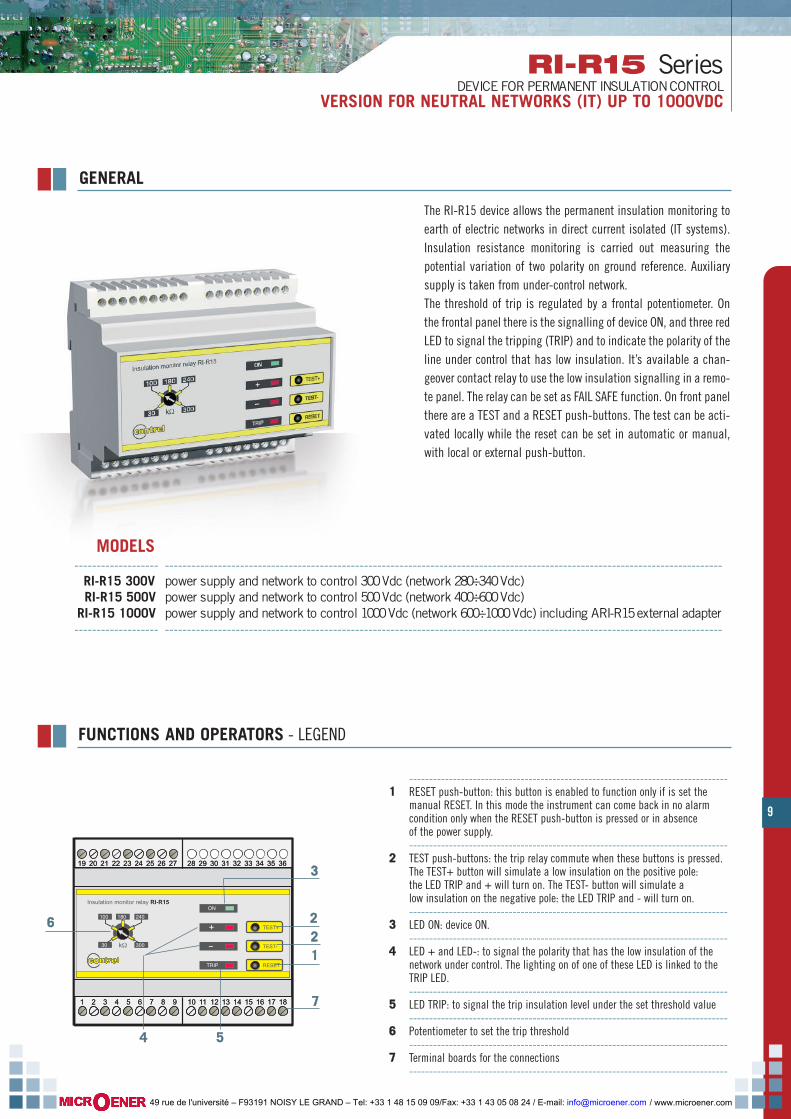
The RI-R15 device allows the permanent insulation monitoring toearth of electric networks in direct current isolated (IT systems).Insulation resistance monitoring is carried out measuring thepotential variation of two polarity on ground reference. Auxiliarysupply is taken from under-control network.The threshold of trip is regulated by a frontal potentiometer. Onthe frontal panel there is the signalling of device ON, and three redLED to signal the tripping (TRIP) and to indicate the polarity of theline under control that has low insulation. It’s available a chan-geover contact relay to use the low insulation signalling in a remo-te panel. The relay can be set as FAIL SAFE function. On front panelthere are a TEST and a RESET push-buttons. The test can be acti-vated locally while the reset can be set in automatic or manual,with local or external push-button.
kΩ
Insulation monitor relay RI-R15ON
TRIP
TEST+
TEST-
RESET
+
-
100
30 300
240180
28 29 30 31 32 33 34 35 3619 20 21 22 23 24 25 26 27 28 29 30 31 32 33 34 35 36
1 2 3 4 5 6 7 8 9 10 11 12 13 14 15 16 17 181 2 3 4 5 6 7 8 9 10 11 12 13 14 15 16 17 18
19 20 21 22 23 24 25 26 27
66
33
112222
77
55
--------------------------------------------------------------------------------11 RESET push-button: this button is enabled to function only if is set the
manual RESET. In this mode the instrument can come back in no alarm condition only when the RESET push-button is pressed or in absence of the power supply.--------------------------------------------------------------------------------
22 TEST push-buttons: the trip relay commute when these buttons is pressed. The TEST+ button will simulate a low insulation on the positive pole: the LED TRIP and + will turn on. The TEST- button will simulate a low insulation on the negative pole: the LED TRIP and - will turn on.--------------------------------------------------------------------------------
33 LED ON: device ON.--------------------------------------------------------------------------------
44 LED + and LED-: to signal the polarity that has the low insulation of the network under control. The lighting on of one of these LED is linked to the TRIP LED.--------------------------------------------------------------------------------
55 LED TRIP: to signal the trip insulation level under the set threshold value--------------------------------------------------------------------------------
66 Potentiometer to set the trip threshold--------------------------------------------------------------------------------
77 Terminal boards for the connections --------------------------------------------------------------------------------
FUNCTIONS AND OPERATORS - LEGEND
44
MODELS------------------- ------------------------------------------------------------------------------------------------------------------------------RI-R15 300V power supply and network to control 300 Vdc (network 280÷340 Vdc)RI-R15 500V power supply and network to control 500 Vdc (network 400÷600 Vdc)RI-R15 1000V power supply and network to control 1000 Vdc (network 600÷1000 Vdc) including ARI-R15 external adapter------------------- ------------------------------------------------------------------------------------------------------------------------------
RI-R15 SeriesDEVICE FOR PERMANENT INSULATION CONTROL
VERSION FOR NEUTRAL NETWORKS (IT) UP TO 1000VDC
/ www.microener.com 49 rue de l'université – F93191 NOISY LE GRAND – Tel: +33 1 48 15 09 09/Fax: +33 1 43 05 08 24 / E-mail: [email protected]
10
RI-R15 SeriesDEVICE FOR PERMANENT INSULATION CONTROLVERSION FOR NEUTRAL NETWORKS (IT) UP TO 1000VDC
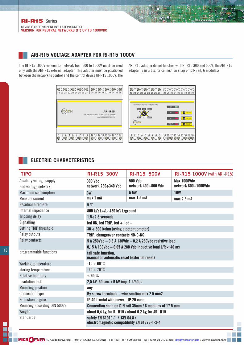
Auxiliary voltage supply and voltage networkMaximum consumptionMeasure currentResidual alternateInternal impedanceTripping delaySignallingSetting TRIP threshold Relay outputsRelay contacts
programmable functions
Working temperaturestoring temperatureRelative humidityInsulation testMounting positionConnection typeProtection degreeMounting according DIN 50022WeightStandards
5 %800 kΩ L+/L- 450 kΩ L/ground1.5÷2.5 secondsled ON, led TRIP, led +, led -30 ÷ 300 kohm (using a potentiometer)TRIP: changeover contacts NO-C-NC5 A 250Vac – 0,3 A 130Vdc – 0,2 A 280Vdc resistive load0,15 A 130Vdc – 0,05 A 280 Vdc inductive load L/R < 40 msfail safe function, manual or automatic reset (external reset)-10 ÷ 60°C-20 ÷ 70°C≤ 95 %2,5 kV 60 sec. / 6 kV imp. 1,2/50µsanyBy screw terminals – wire section max 2.5 mm2IP 40 frontal with cover - IP 20 caseConnection snap on DIN rail 35mm / 6 modules of 17.5 mmabout 0,4 kg for RI-R15 / about 0.2 kg for ARI-R15safety EN 61010-1 / CEI 64.8 / electromagnetic compatibility EN 61326-1-2-4
TIPO RI-R15 300V RI-R15 500V 300 Vdcnetwork 280÷340 Vdc
3Wmax 1 mA
500 Vdcnetwork 400÷600 Vdc
5.5Wmax 1.5 mA
RI-R15 1000V (with ARI-R15)Max 1000Vdcnetwork 600÷1000Vdc
10Wmax 2.5 mA
ELECTRIC CHARACTERISTICS
ARI-R15 VOLTAGE ADAPTER FOR RI-R15 1000V
The RI-R15 1000V version for network from 600 to 1000V must be usedonly with the ARI-R15 external adapter. This adapter must be positionedbetween the network to control and the control device RI-R15 1000V. The
ARI-R15 adapter do not function with RI-R15 300 and 500V. The ARI-R15adapter is in a box for connection snap on DIN rail, 6 modules:
1 2 3 4 5 6 7 8 9 10 11 12 13 14 15 16 17 18
28 29 30 31 32 33 34 35 3619 20 21 22 23 24 25 26 27
contrel ARI-R15INSULATION MONITOR VOLTAGE ADAPTER
max 700/800/900/1000Vdc k
Insulation monitor relay RI-R15
contrel
ON
TRIP
TEST+
TEST-
RESET
+
-
100
30 300
240180
1 2 3 4 5 6 7 8 9 10 11 12 13 14 15 16 17 18
28 29 30 31 32 33 34 35 3619 20 21 22 23 24 25 26 27
/ www.microener.com 49 rue de l'université – F93191 NOISY LE GRAND – Tel: +33 1 48 15 09 09/Fax: +33 1 43 05 08 24 / E-mail: [email protected]
11
RI-R15 SeriesDEVICE FOR PERMANENT INSULATION CONTROL
VERSION FOR NEUTRAL NETWORKS (IT) UP TO 1000VDC
DIMENSIONS
73
54
105
90 90
105
RI-R15 300V / RI-R15 500V WIRING CONNECTION - LEGEND
1 2 3 4 5 6 7 8 9 10 11 12 13 14 15 16 17 18PE
V +
F.S.+
Vau
x:V
con
trol*
19 20 21 22 23 24 25 26 27 28 29 30 31 32 33 34 35 36
RI-R15INSULATION MONITOR
V - RES+ T-NC T-C T-NO
conn
essi
one
PE
INSULATED LINE Vdc LOAD+
_
PE
RES- F.S.-
resetremotemanual
Fail Safefunction
relay output TRIP
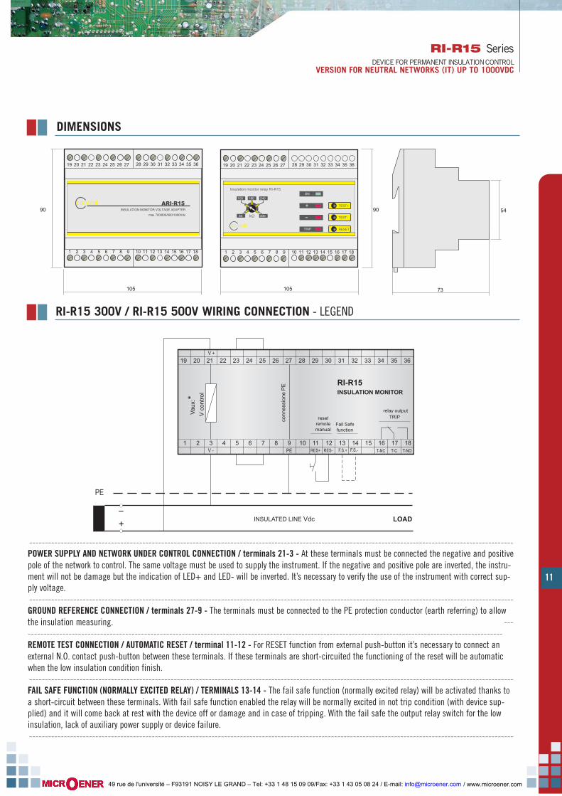
----------------------------------------------------------------------------------------------------------------------------------------------------------POWER SUPPLY AND NETWORK UNDER CONTROL CONNECTION / terminals 21-3 - At these terminals must be connected the negative and positivepole of the network to control. The same voltage must be used to supply the instrument. If the negative and positive pole are inverted, the instru-ment will not be damage but the indication of LED+ and LED- will be inverted. It’s necessary to verify the use of the instrument with correct sup-ply voltage.----------------------------------------------------------------------------------------------------------------------------------------------------------GROUND REFERENCE CONNECTION / terminals 27-9 - The terminals must be connected to the PE protection conductor (earth referring) to allowthe insulation measuring. ----------------------------------------------------------------------------------------------------------------------------------------------------------REMOTE TEST CONNECTION / AUTOMATIC RESET / terminal 11-12 - For RESET function from external push-button it’s necessary to connect anexternal N.O. contact push-button between these terminals. If these terminals are short-circuited the functioning of the reset will be automaticwhen the low insulation condition finish.----------------------------------------------------------------------------------------------------------------------------------------------------------FAIL SAFE FUNCTION (NORMALLY EXCITED RELAY) / TERMINALS 13-14 - The fail safe function (normally excited relay) will be activated thanks toa short-circuit between these terminals. With fail safe function enabled the relay will be normally excited in not trip condition (with device sup-plied) and it will come back at rest with the device off or damage and in case of tripping. With the fail safe the output relay switch for the lowinsulation, lack of auxiliary power supply or device failure.----------------------------------------------------------------------------------------------------------------------------------------------------------
/ www.microener.com 49 rue de l'université – F93191 NOISY LE GRAND – Tel: +33 1 48 15 09 09/Fax: +33 1 43 05 08 24 / E-mail: [email protected]

12
RI-R15 SeriesDEVICE FOR PERMANENT INSULATION CONTROLVERSION FOR NEUTRAL NETWORKS (IT) UP TO 1000VDC
TRIP RELAY OUTPUT / terminals 16-17-18 - To signal externally the TRIP threshold intervention it’s available a voltage changeover contact relay.The wiring connection shows the contacts with the device off or on in rest condition with FAIL SAFE function disable (relay normally not excited).With FAIL SAFE function enabled the relay will be normally excited in not trip condition (with device supplied) and it will come back at rest withthe device off or damage and in case of tripping.---------------------------------------------------------------- ------------------------------------------------------------------------------------------CONNEXION TO THE EXTERNAL ADAPTERS - To activate the instrument it’s necessary to make the short-circuit between the following terminals23-25 and 5-7. This terminals are used to connect the external adapters when they are used (see specific manual).----------------------------------------------------------------------------------------------------------------------------------------------------------
1 2 3 4 5 6 7 8 9 10 11 12 13 14 15 16 17 18F.S.+
resetremotemanual
19 20 21 22 23 24 25 26 27 28 29 30 31 32 33 34 35 36
RI-R15 1000VINSULATION MONITOR
RES+
INSULATED LINE Vdc (MAX 700 / 800 / 900 / 1000 V) LOAD
RES- F.S.-
Fail Safefunction
1 2 3 4 5 6 7 8 9 10 11 12 13 14 15 16 17 18
V +
Vau
x:V
con
trol*
19 20 21 22 23 24 25 26 27 28 29 30 31 32 33 34 35 36
ARI-R15INSULATIONMONITORVOLTAGEADAPTER
V -
for l
ine
600÷
700V
dc
for l
ine
700÷
800V
dc
for l
ine
800÷
900V
dc
for l
ine
900÷
1000
Vdc
IN-A
IN-B
IN+A
IN+B
+
_
PE
T-NC T-C T-NO
relay output TRIP
REF
PE
In this version is present obligatory the ARI-R15 adapter.The connections of the relay output, remote reset and fail safe function remain the same while the connections to the network under control andthe earth reference has been changed.----------------------------------------------------------------------------------------------------------------------------------------------------------POWER SUPPLY AND NETWORK UNDER CONTROL CONNECTION - terminals 21-3 of the ARI-R15 adapterAt these terminals must be connected the negative and positive pole of the network to control.------------------------------------------------------------------------------------------------------------------------------------------------------GROUND REFERENCE CONNECTION - terminal 9 of the ARI-R15 adapter----------------------------------------------------------------------------------------------------------------------------------------------------------ARI-R15 AND RI-R15 1000V CONNECTIONS - Terminals 5-23-27 to connect between the control device and the adapterTerminals to connect depending the network under control:
If the network voltage is exactly an expected valuefor two outputs (700 / 800 / 900V) it’s better to usethe output with the upper nominal values.
For example for a network at 800V is better to usethe output with the terminals 32-14.
tensione di rete ARI-R15 RI-R15 1000V
600÷700V dc terminals 28 - 10 terminals 25 - 7
700÷800V dc terminals 30 - 12 terminals 25 - 7
800÷900V dc terminals 32 - 14 terminals 25 - 7
900÷1000V dc terminals 34 - 16 terminals 25 - 7
RI-R15 1000V WIRING CONNECTION - LEGEND
/ www.microener.com 49 rue de l'université – F93191 NOISY LE GRAND – Tel: +33 1 48 15 09 09/Fax: +33 1 43 05 08 24 / E-mail: [email protected]

13
RI-F22 seriesRI-R22 seriesRI-R38 series
INSULATION MONITORING - VERSIONS FOR NETWORKS ac MAX 400 V
GENERAL
1 2 3 4 5 6
10 11 127 8 9
TEST
RESET
103050100 150
RI-R38INSULATIONMONITOR
kΩ
ON
TRIP
25
5075
100 ONTRIP TEST
RESETRI-R22
kΩ ONTRIP TEST
RI-F22
connttrreellcontrelconnttrreellcontrel
connttrreellcontrelconnttrreellcontrel connttrreellcontrelconnttrreellcontrel
RI-R38----------------------------------------------------------------
11 LED ON green active device’s indication----------------------------------------------------------------
22 LED TRIP red signal of trip for low insulation----------------------------------------------------------------
33 TEST button device functioning testing----------------------------------------------------------------
44 RESET button trip signalling reset (manual reset functions)----------------------------------------------------------------
55 micro switches for trip threshold adjusting----------------------------------------------------------------
RI-F22 / RI-R22----------------------------------------------------------------
11 Potentiometer for adjusting insulation’s resistance(only for model RI-R22)----------------------------------------------------------------
22 Manual resetting button (only for model RI-R22)----------------------------------------------------------------
33 Test button----------------------------------------------------------------
44 Signalling lamp of auxiliary supply (green LED)----------------------------------------------------------------
55 Signalling lamp for relay tripped (red LED)----------------------------------------------------------------
FUNCTIONS AND OPERATORS - LEGEND
MODELS----------------------------------- --------------------------------------------------------
RI-F22 fixed threshold Vaux: 230 V 50-60 Hz (standard version)RI-F22 fixed threshold Vaux: 110 V 50-60 Hz (optional version)
----------------------------------- --------------------------------------------------------RI-R22 adjustable threshold Vaux: 230 V 50-60 Hz (standard version)RI-R22 adjustable threshold Vaux: 110 V 50-60 Hz (optional version)----------------------------------- --------------------------------------------------------RI-R38 adjustable threshold Vaux: 230 V 50-60 Hz (standard version)RI-R38 adjustable threshold Vaux: 110 V 50-60 Hz (optional version)----------------------------------- --------------------------------------------------------
11
22
44
55 33
22
3311
44
55
33
55
44
These devices allow insulation monitoring onearth of electric networks in alternating 230 Vand isolated 400 V (IT systems).Insulation resistance monitoring is carried outapplying a measure’s signalling in direct-cur-rent between isolated network and earth.Surveying electric leakage set up on earth it’spossible to measure insulation level.Versions with fixed trip threshold are availableand they are very cheap.There are also versions with possibility of adju-stable calibration of trip threshold.On frontal panel, devices have signal for activi-ty ON, for TRIP (low insulation), a test button, areset button (only for versions with adjustablethreshold) and a potentiometer for setting thethreshold of tripping (model RI-R22) or microswitches (model RI-R38).
/ www.microener.com 49 rue de l'université – F93191 NOISY LE GRAND – Tel: +33 1 48 15 09 09/Fax: +33 1 43 05 08 24 / E-mail: [email protected]

14
RI-F22 seriesRI-R22 seriesRI-R38 seriesINSULATION MONITORINGVERSIONS FOR NETWORKS ac MAX 400 V
64
68
52,5
85,5
85
25
5075
100 ONTRIP TEST
RESETRI-R22
kΩ
connttrreellcontrelconnttrreellcontrel
1 2 3 4 5 6
10 11 127 8 9
TEST
RESET
103050100 150
RI-R38INSULATIONMONITOR
kΩ
ON
TRIP
connttrreellcontrelconnttrreellcontrel
52,5
58
45
65
44
DIMENSIONS
ELECTRIC CHARACTERISTICS
Auxiliary supply voltage 230 V 50-60 Hz ± 20 % standard110 V 50-60 Hz ± 20 % optional
Self-consumption 3 VA MAX
RI-F22 / RI-R22 12 V MAXRI-R38 24 V MAX
Network voltage
Measure's voltage
RI-F22 / RI-R22 0.1 mA MAXRI-R38 0.5 mA MAX
Measure's current
RI-F22 / RI-R22 100 kohmRI-R38 250 kohm
Internal impedance
RI-F22 fixed 100 kohmRI-R22 adjustable 25 ÷ 100 kohm (by potentiometer)RI-R38 adjustable 10 ÷ 150 kohm (4 levels by micro switches)
Tripping threshold setting
about 1 secondTripping late
led ON - led TRIPbuttons TEST and RESET (RESET is not available for RI-F22)
Signals and operators
- 10 …+ 60 °CWorking temperature- 20 …+ 70 °CStoring temperature< 90 %Relative humidity
Insulation testindifferentAssembling positionby screw terminals - wire section MAX 4 mm2Connection typeIP 40 frontal with cap - IP 20 caseProtection's degreeeasy connection snap on DIN rail 35 mm / 3 modules of 17.5 mmMounting according with DIN 50022approximately 300 gWeightCEI-EN 61010-1 / CEI-EN 61557-8 / VDE 0413 part.8 / CEI-EN 61326-1Standard reference
RI-F22 / RI-R22 24 ÷ 230 Vac +10 % (400 V on 3 phase network with neutral)RI-R38 24 ÷ 440 Vac +10 % (760 V on 3 phase network with neutral)
relay switch contact NO-C-NC MAX 5 A 250 VacOutput
RI-F22 | RI-R22 RI-R38
/ www.microener.com 49 rue de l'université – F93191 NOISY LE GRAND – Tel: +33 1 48 15 09 09/Fax: +33 1 43 05 08 24 / E-mail: [email protected]

15
RI-F22 seriesRI-R22 seriesRI-R38 series
INSULATION MONITORINGVERSIONS FOR NETWORKS ac MAX 400 V
WIRING DIAGRAMS - LEGEND
1 2 3 4 5 6 7 8 9PE
10 11
RI-F22 / RI-R22
AUX1
INSULATED LINEmax 230 Vac
L1
N
OUT-NC OUT-NOOUT-CAUX2 VC RESET
Vaux
PE
L2
L3 LOAD
1 2 3 4 5 6 7 8 9PE
10 11
RI-R38
AUX1
INSULATED LINEmax 440 Vac
L1
N
OUT-NC OUT-NOOUT-CAUX2 VC RESET
Vaux
PE
L2
L3 LOAD
12
12
RI-F22 / RI-R22--------------------------------------------------------------------------AUXILIARY SUPPLY - terminals 1-3auxiliary supply available from under-control network--------------------------------------------------------------------------INSULATION MONITORING - terminals 4-9the two terminals have to be connected between under-controlnetwork and measure’s referring earth (max. applicable voltagebetween these terminals is 230 V, so it’s possible apply insulationmonitoring on single phase networks till 230 V, three phasenetworks three-wires without neutral till 230 V and three phasenetworks with neutral till 400 V)--------------------------------------------------------------------------RELAYS’ OUTPUT CONNECTIONS - terminals 6-7-8--------------------------------------------------------------------------CONNECTIONS FOR REMOTE SIGNALLINGby relays in switch voltage-free max 5 A 250 V on resistive load--------------------------------------------------------------------------EVENTUAL CONNECTION FOR AUTOMATIC OR REMOTE RESET(only for RI-R22) it is required to connect a NC button betweenterminal 10 and earth’s conductor PE and to link with a bondterminals 9 and 10 themselves--------------------------------------------------------------------------EVENTUAL CONNECTION FOR REMOTE TEST (only for version RI-R22) it is required to connect a NO buttonbetween terminal 5 and earth’s conductor PE--------------------------------------------------------------------------
RI-R38--------------------------------------------------------------------------AUXILIARY SUPPLY - terminals 1-3auxiliary supply available from under-control network--------------------------------------------------------------------------INSULATION MONITORING - terminals 5-11the two terminals have to be connected between under-controlnetwork and measure’s referring earth. Terminal 5 has to beconnected between under-control network single phase or three phaseand neutral conductor. If three phase network is three-wire, theterminal has to be connected to a phase. max. applicable voltagebetween these terminals is 230 V, so it’s possible apply insulationmonitoring on single phase networks up to 440 V, three phasenetworks three-wire without neutral up to 440 V and three phasenetworks with neutral up to 760 V--------------------------------------------------------------------------RELAYS’ OUTPUT CONNECTIONS - terminals 7-8-9--------------------------------------------------------------------------CONNECTIONS FOR REMOTE SIGNALLINGby relays in switch voltage-free max 5 A 250 V on resistive load--------------------------------------------------------------------------CONNECTION FOR AUTOMATIC OR REMOTE RESET - terminal 12--------------------------------------------------------------------------
/ www.microener.com 49 rue de l'université – F93191 NOISY LE GRAND – Tel: +33 1 48 15 09 09/Fax: +33 1 43 05 08 24 / E-mail: [email protected]

ARI-R100 seriesADAPTER FOR NETWORKS TILL 1000 VacVOLTAGE ADAPTER FOR INSULATION MONITORING RI-R38
16
GENERAL
contrelcontrel ARI-R100AUXILIARY VOLTAGE ADAPTER FOR RI INSULATION MONITOR
MADE IN EU
1
V aux:230V 50-60Hz
3
PE
94
LINE INPUTmax. 1000V 50-60Hz
23
to RIinsulation monitor
auxiliarysupply
connection toRI-R38
connection toreference earth
connection toline in check
FUNCTIONS AND OPERATORS - LEGENDA
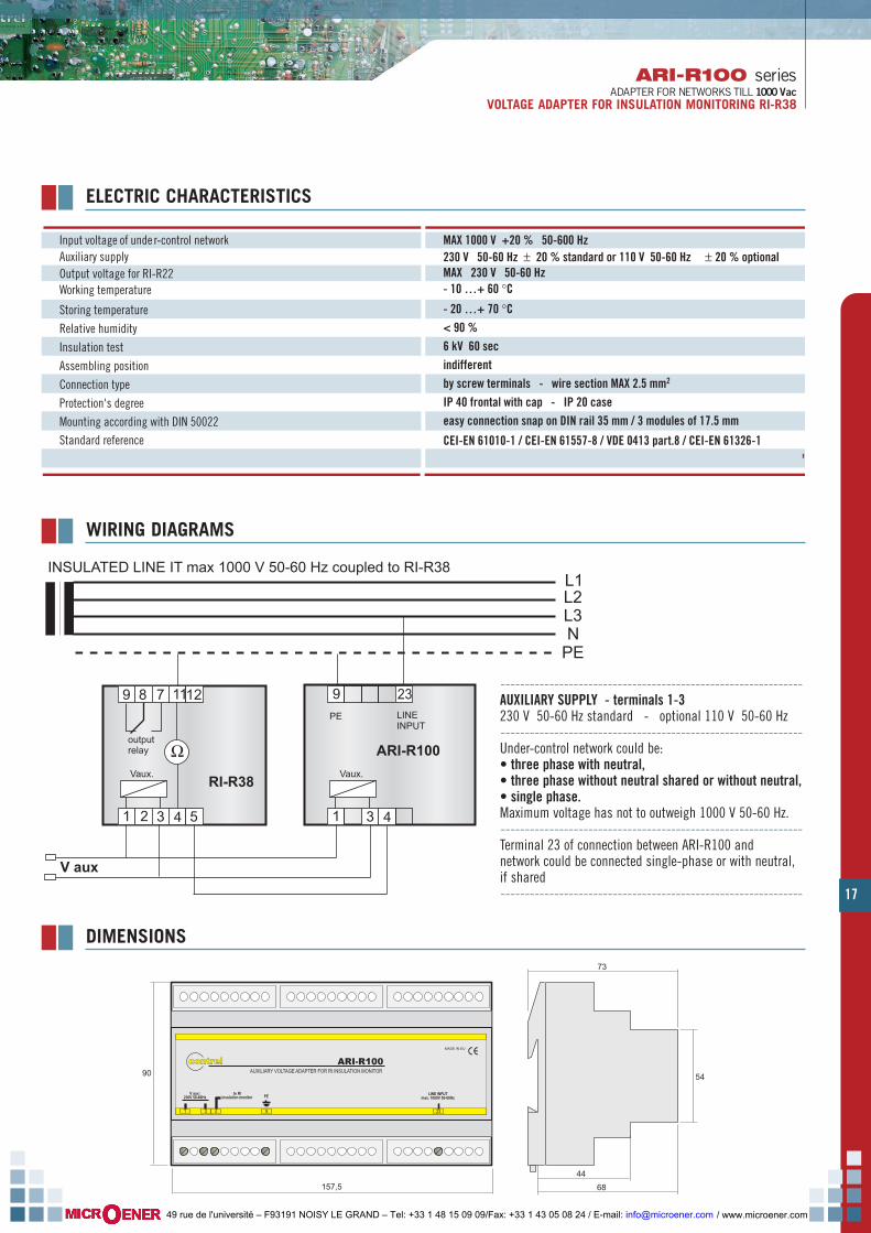
ARI-R100 is an adapter which allow the use of insu-lation monitors RI-R38 on single phase and threephase up to 1000 V 50-60 Hz.the adapter have to be connected between RI-R38insulation ralay and under-control network.Under-control network could be three phase networkwith neutral, three phase without neutral and singlephase network.Maximum voltage has not to outweigh 1000 V 50-60Hz (application of adapter for networks in direct-current or with strong presence of direct-currentcomponents is not possible).ARI-R100 needs an auxiliary supply (normally thesame of RI-R38 relay).
MODELS--------------- --------------------------------------------------------------------------------------ARI-R100 Vaux: 230 V 50-60 Hz (standard version)
--------------- --------------------------------------------------------------------------------------ARI-R100 Vaux: 110 V 50-60 Hz (optional version)
--------------- --------------------------------------------------------------------------------------
/ www.microener.com 49 rue de l'université – F93191 NOISY LE GRAND – Tel: +33 1 48 15 09 09/Fax: +33 1 43 05 08 24 / E-mail: [email protected]
17
ARI-R100 seriesADAPTER FOR NETWORKS TILL 1000 Vac
VOLTAGE ADAPTER FOR INSULATION MONITORING RI-R38
157,5
90
contrelcontrel ARI-R100AUXILIARY VOLTAGE ADAPTER FOR RI INSULATION MONITOR
MADE IN EU
1
V aux:230V 50-60Hz
3
PE
94
LINE INPUTmax. 1000V 50-60Hz
23
to RIinsulation monitor
73
68
44
54
Input voltage of unde r-control network MAX 1000 V +20 % 50-600 Hz 230 V 50-60 Hz ± 20 % standard or 110 V 50-60 Hz ± 20 % optionalAuxiliary supply
- 10 …+ 60 °CWorking temperature
- 20 …+ 70 °CStoring temperature< 90 %Relative humidity6 kV 60 secInsulation testindifferentAssembling positionby screw terminals - wire section MAX 2.5 mm2Connection typeIP 40 frontal with cap - IP 20 caseProtection's degreeeasy connection snap on DIN rail 35 mm / 3 modules of 17.5 mmMounting according with DIN 50022
CEI-EN 61010-1 / CEI-EN 61557-8 / VDE 0413 part.8 / CEI-EN 61326-1Standard reference
MAX 230 V 50-60 HzOutput voltage for RI-R22
ELECTRIC CHARACTERISTICS
L1L2L3N
PE
INSULATED LINE IT max 1000 V 50-60 Hz coupled to RI-R38
9 8 7 1112
ΩVaux.
outputrelay
RI-R38
9 23
Vaux.
PE
ARI-R100
LINEINPUT
1 3 4 52 1 3 4
V aux
WIRING DIAGRAMS
--------------------------------------------------------------AUXILIARY SUPPLY - terminals 1-3230 V 50-60 Hz standard - optional 110 V 50-60 Hz--------------------------------------------------------------Under-control network could be:• three phase with neutral, • three phase without neutral shared or without neutral, • single phase.Maximum voltage has not to outweigh 1000 V 50-60 Hz.--------------------------------------------------------------Terminal 23 of connection between ARI-R100 andnetwork could be connected single-phase or with neutral,if shared--------------------------------------------------------------
DIMENSIONS
/ www.microener.com 49 rue de l'université – F93191 NOISY LE GRAND – Tel: +33 1 48 15 09 09/Fax: +33 1 43 05 08 24 / E-mail: [email protected]

18
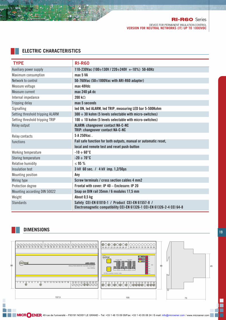
RI-R60 SeriesDEVICE FOR INSULATION PERMANENT CONTROL VERSION FOR NEUTRAL NETWORKS (IT) UP TO 1000VAC
GENERAL
RI-R60 is a device that allows to control the insulation to earth in alternatingneutral networks up to 760 V (IT systems) in direct insertion and in network upto 1000V with ARI-R60 adapter.Putting a continuous component measure signal between the insulated lineand earth it’s possible to control the insulation resistance reading the disper-sion current generated to earth.These devices have two trip thresholds (ALARM and TRIP) adjustable using thefrontal micro-switches to signal when the insulation go under the thresholdlevel. The frontal LED signalling the trip. Two free voltage changeover contactsrelays allow the remote trip signalling. The relays can be programmed with thefail safe (normally excited). The device is supplied on the front panel of a TESTand a RESET push-buttons. The test can be activated thanks to the push-but-ton on the device or to external push-button while the reset that can be set inmanual or in automatic and activated, as the test, with the local or remotepush-button.The level of the insulation resistance is displayed on the bar LED on the frontpanel with scale 5-500 kohm at 8 point.
MODELS----------------- ---------------------------------------------------------------------------------------------------------------------RI-R60-760 network voltage 760Vac max , Uaux 110-230V 50-60 Hz (100÷130 / 220÷240V ± 10%)
----------------- ---------------------------------------------------------------------------------------------------------------------RI-R60-1000 network voltage 1000Vac max (with ARI-R60 adapter), Uaux 110-230V 50-60 Hz (100÷130 /
220÷240V ± 10%)----------------- ---------------------------------------------------------------------------------------------------------------------
INSTALLATION
The installation must be carried out by qualified and authorized person-nel and in absence of voltage. Make sure that the instrument is O.K. andit has not suffered any damage during transport. Make sure that the vol-tage supply are compatible with the operating voltage of instrument.
The device is a 6 modules (17.5mm) DIN version with snap on 35mm DINrail. It has a sealable transparent frontal protection cover.The green LED ON will bright after the connections are set and the instru-ment is power on.
22
11 66
44
77
99--------------------------------------------------------------------------------
11 Pulsante di RESET. Questo pulsante ha effettiva funzionalità solo se impostato il funzionamento in RESET manuale.--------------------------------------------------------------------------------
22 RESET push-button. Only when it’s set the manual reset functioning this push-button is enable.--------------------------------------------------------------------------------
33 TEST push-button. Pressing the TEST push-button cause the tripping of the ALARM and the TRIP and the output relay commute.--------------------------------------------------------------------------------
44 LED ON to signal the device turned ON.--------------------------------------------------------------------------------
55 LED TRIP for the signalling overcoming the TRIP threshold.--------------------------------------------------------------------------------
66 LED ALARM for the signalling overcoming the ALARM threshold.--------------------------------------------------------------------------------
77 LED bar to indicate the measured insulation resistance level. With all LED on the insulation level is lower than 5 kohm, with all led off the insulation level upper is than 500 kohm.--------------------------------------------------------------------------------
88 terminals board--------------------------------------------------------------------------------
99 micro-switches to set the alarm threshold--------------------------------------------------------------------------------
1100 micro-switches to set the trip threshold--------------------------------------------------------------------------------
FUNCTIONS AND OPERATORS - LEGEND
33
55
88
/ www.microener.com 49 rue de l'université – F93191 NOISY LE GRAND – Tel: +33 1 48 15 09 09/Fax: +33 1 43 05 08 24 / E-mail: [email protected]
19
RI-R60 SeriesDEVICE FOR PERMANENT INSULATION CONTROL
VERSION FOR NEUTRAL NETWORKS (IT) UP TO 1000VDC
Auxiliary power supplyMaximum consumptionNetwork to controlMeasure voltageMeasure currentInternal impedanceTripping delaySignallingSetting threshold tripping ALARMSetting threshold tripping TRIPRelay output
Relay contactsfunctions
Working temperatureStoring temperatureRelative humidityInsulation testMounting positionWiring typeProtection degreeMounting according DIN 50022WeightStandards
110-230Vac (100÷130V / 220÷240V +-10%) 50-60Hzmax 5 VA50-760Vac (50÷1000Vac with ARI-R60 adapter)max 48Vdcmax 240 µA dc200 kΩmax 5 secondsled ON, led ALARM, led TRIP, measuring LED bar 5-500Kohm300 ÷ 30 kohm (5 levels selectable with micro-switches)100 ÷ 10 kohm (5 levels selectable with micro-switches)ALARM: changeover contact NA-C-NC TRIP: changeover contact NA-C-NC5 A 250Vac .Fail safe function for both outputs, manual or automatic reset, local and remote test and reset push-button-10 ÷ 60°C-20 ÷ 70°C≤ 95 %3 kV 60 sec. / 4 kV imp. 1,2/50µsAnyScrew terminals / cross section cables 4 mm2Frontal with cover: IP 40 – Enclosure: IP 20Snap on DIN rail 35mm / 6 modules 17,5 mmAbout 0,5 kgSafety CEI-EN 61010-1 / Product CEI-EN 61557-8 /Electromagnetic compatibility CEI-EN 61326-1 CEI-EN 61326-2-4 CEI 64-8
TYPE RI-R60
ELECTRIC CHARACTERISTICS
DIMENSIONS
73
45
157,5
90 90
105
1 2 3 4 5 6 7 8 9 10 11 12 13 14 15 16 17 18
28 29 30 31 32 33 34 35 3619 20 21 22 23 24 25 26 27
kΩTEST
RESET
300 100
offman
F.S.onauto
RESET
10204060
5030
80150
kΩTRIP
offman
F.S.onauto
RESET
ALARM kΩ
RI-R60 insulation monitor relay
contrelcontrel
500
ON
ALARM
200
100
60
40
20
10
< 5
kΩ
TRIP
contrelcontrel ARI-R60INSULATION MONITOR VOLTAGE ADAPTER
max 1000Vac
1 2 3 4 5 6 7 8 9 10 11 12 13 14 15 16 17 18 19 20 21 22 23 24 25 26 27
28 29 30 31 32 33 34 35 36 37 38 39 40 41 42 43 44 45 46 47 48 49 50 51 52 53 54
/ www.microener.com 49 rue de l'université – F93191 NOISY LE GRAND – Tel: +33 1 48 15 09 09/Fax: +33 1 43 05 08 24 / E-mail: [email protected]
20
RI-R60 SeriesDEVICE FOR PERMANENT INSULATION CONTROLVERSION FOR NEUTRAL NETWORKS (IT) UP TO 1000VDC
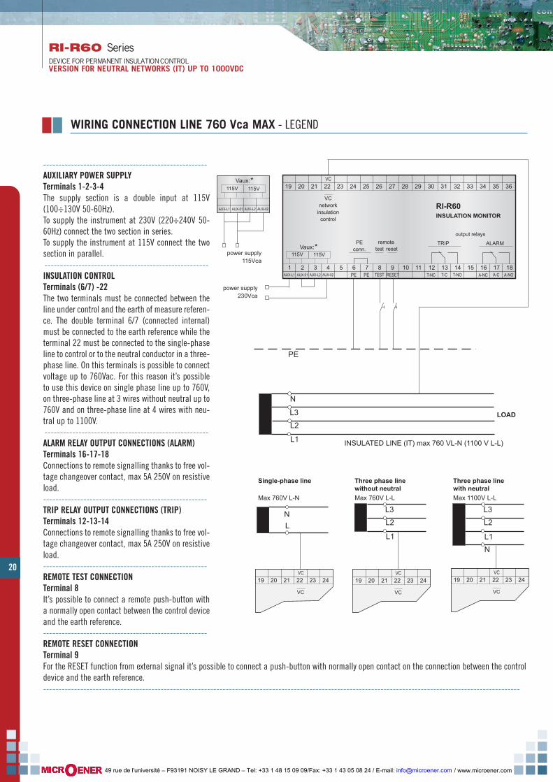
-----------------------------------------------------AUXILIARY POWER SUPPLYTerminals 1-2-3-4The supply section is a double input at 115V(100÷130V 50-60Hz).To supply the instrument at 230V (220÷240V 50-60Hz) connect the two section in series.To supply the instrument at 115V connect the twosection in parallel.-----------------------------------------------------INSULATION CONTROLTerminals (6/7) -22The two terminals must be connected between theline under control and the earth of measure referen-ce. The double terminal 6/7 (connected internal)must be connected to the earth reference while theterminal 22 must be connected to the single-phaseline to control or to the neutral conductor in a three-phase line. On this terminals is possible to connectvoltage up to 760Vac. For this reason it’s possibleto use this device on single phase line up to 760V,on three-phase line at 3 wires without neutral up to760V and on three-phase line at 4 wires with neu-tral up to 1100V.-----------------------------------------------------ALARM RELAY OUTPUT CONNECTIONS (ALARM)Terminals 16-17-18Connections to remote signalling thanks to free vol-tage changeover contact, max 5A 250V on resistiveload.-----------------------------------------------------TRIP RELAY OUTPUT CONNECTIONS (TRIP)Terminals 12-13-14Connections to remote signalling thanks to free vol-tage changeover contact, max 5A 250V on resistiveload.-----------------------------------------------------REMOTE TEST CONNECTIONTerminal 8It’s possible to connect a remote push-button witha normally open contact between the control deviceand the earth reference.-----------------------------------------------------REMOTE RESET CONNECTIONTerminal 9For the RESET function from external signal it’s possible to connect a push-button with normally open contact on the connection between the controldevice and the earth reference.----------------------------------------------------------------------------------------------------------------------------------------------------------
WIRING CONNECTION LINE 760 Vca MAX - LEGEND
1 2 3 4 5 6 7 8 9 10 11 12 13 14 15 16 17 18TEST
reset
19 20 21 22 23 24 25 26 27 28 29 30 31 32 33 34 35 36
RI-R60INSULATION MONITOR
RESET T-NC T-C T-NO A-NC A-C A-NO
output relays
testPE
conn.
PE PE
remote TRIP ALARM
VC
VCnetwork
insulationcontrol
power supply230Vca
115V 115V
LOAD
L1
N
PE
L2L3
INSULATED LINE (IT) max 760 VL-N (1100 V L-L)
115V*
power supply115Vca
LN
Single-phase line
Max 760V L-N
19 20 21 22 23 24 VC
VC
L1
L2L3
Three phase linewithout neutralMax 760V L-L
19 20 21 22 23 24 VC
VC
L1
L2L3
Three phase linewith neutralMax 1100V L-L
19 20 21 22 23 24 VC
VC
N
AUX-L1 AUX-01 AUX-L2 AUX-02
Vaux:115V
*Vaux:
AUX-L1 AUX-01 AUX-L2 AUX-02
/ www.microener.com 49 rue de l'université – F93191 NOISY LE GRAND – Tel: +33 1 48 15 09 09/Fax: +33 1 43 05 08 24 / E-mail: [email protected]

21
RI-R60 SeriesDEVICE FOR PERMANENT INSULATION CONTROL
VERSION FOR NEUTRAL NETWORKS (IT) UP TO 1000VDC
-----------------------------------------------------------------------AUXILIARY POWER SUPPLY - TERMINALS 1-2-3-4The supply section is a double input at 115V (100÷130V 50-60Hz).To supply the instrument at 230V (220÷240V 50-60Hz) connect thetwo section in series.To supply the instrument at 115V connect the two section in parallel.-----------------------------------------------------------------------INSULATION CONTROL - TERMINALS (6/7) -22The two terminals must be connected between the line under controland the earth of measure reference.The double terminal 6/7 (connected internal) must be connected tothe earth reference while the terminal 22 must be connected to theARI-R60 adapter-----------------------------------------------------------------------ALARM RELAY OUTPUT CONNECTIONS (ALARM) - TERMINALS 16-17-18Connections to remote signalling thanks to free voltage changeovercontact, max 5A 250V on resistive load.-----------------------------------------------------------------------TRIP RELAY OUTPUT CONNECTIONS (TRIP) - TERMINALS 12-13-14Connections to remote signalling thanks to free voltage changeovercontact, max 5A 250V on resistive load.-----------------------------------------------------------------------REMOTE TEST CONNECTION - TERMINAL 8It’s possible to connect a remote push-button with a normally opencontact between the control device and the earth reference.-----------------------------------------------------------------------REMOTE RESET CONNECTION - TERMINAL 9For the RESET function from external signal it’s possible to connect apush-button with normally open contact on the connection betweenthe control device and the earth reference.-----------------------------------------------------------------------
1 2 3 4 5 6 7 8 9 10 11 12 13 14 15 16 17 18TEST
reset
19 20 21 22 23 24 25 26 27 28 29 30 31 32 33 34 35 36
RI-R60INSULATION MONITOR
RESET T-NC T-C T-NO A-NC A-C A-NO
testPE
conn.
PE PE
remote TRIP ALARM
VC
to adapter ARI-R60(VC insulation control
line 1000V)
power supply230Vca
115V 115V
LOAD
L1
N
PE
L2L3
INSULATED LINE (IT) max 1000 V 50-60Hz
115V*
power supply115Vca
AUX-L1 AUX-01 AUX-L2 AUX-02
Vaux:115V
*Vaux:
AUX-L1 AUX-01 AUX-L2 AUX-02
924 23 4
ARI-R60ADAPTER
PE
output relays
WIRING CONNECTION LINE 1.000 Vca MAX - LEGEND
FUNZIONALITY
In normally condition with the insulation value upper than alarm and tripthresholds the green LED of the device is turned on and the status of thebar led depending of the insulation resistance level measured (with allled off the insulation value is upper than 500 kohm, with all LED on themeasured LED lower than 5 kohm).By pressing the TEST push-button at least 5 seconds (delay time) thealarm and trip signalling with relative LED will be activated, the outputrelays commute and the LED bar turn on (simulated value lower than 5kohm).
Depending the set of the micro-switches the RESET can be automaticwhen the TEST push-button is released or manual with the local or remo-te RESET push-button.In case of low insulation on the line (insulation resistance value lowerthan threshold set) the ALARM and possibly the TRIP signalling will beactivated as the correspondent output relays. The Signalling will disap-pear only after that on the line come back an insulation level upper thanthe threshold set.
NOTES - It’s not possible to use more than one instrument on a line because the measure of the resistance could be not correct for the overlap ofthe signal.The presence of strong continuous component on the network under control could create some problems for the correct functioning of the device.
/ www.microener.com 49 rue de l'université – F93191 NOISY LE GRAND – Tel: +33 1 48 15 09 09/Fax: +33 1 43 05 08 24 / E-mail: [email protected]

22
The devices allow insulation monitoring to earth of out-voltage networksin order to carry out a preventive monitoring on insulation level of devi-ce. Preventive monitoring is really important in case of applicationswhich are not used permanently (for example: motors, fire-engines, andso on). In these applications, humidity and condensate can cause aserious decrease in insulation’s level and obstruct correct functioning atthe moment of applications’ activation.Insulation resistance’s monitoring is carried out applying a measure’ssignalling in direct-current component between isolated network andearth. Surveying leakage current to earth it’s possible to measure insu-lation’s level.This device allow regulation of trip threshold by micro switches.Devices have on frontal panel signal of active device ON, signal TRIP(low insulation), a test button and micro switches series for regulatingtrip threshold.
GENERAL
1 2 3 4 5 6
10 11 127 8 9
TEST12,557,5
RI-SMINSULATIONMONITOR
MΩ
ON TRIP
contrelcontrel
ON0,10,250,5
FAIL SAFEOFF
10
FUNCTIONS AND OPERATORS - LEGEND
11
44
22
33
RI-SM seriesINSULATION MONITORINGVERSIONS FOR OUT-VOLTAGE NETWORK
58
44
45
65
52,5
85,5
1 2 3 4 5 6
10 11 127 8 9
TEST12,557,5
RI-SMINSULATIONMONITOR
MΩ
ON TRIP
contrelcontrel
ON0,10,250,5
FAIL SAFEOFF
10
DIMENSIONS
------------------------------------------------------------------------------------11 green led ON indication of active device
------------------------------------------------------------------------------------22 red led TRIP trip signal for low insulation
------------------------------------------------------------------------------------33 test button for testing device’s serviceability
------------------------------------------------------------------------------------44 micro switches for selecting trip threshold
------------------------------------------------------------------------------------
MODELS--------------- --------------------------------------------------------------------------------------
RI-SM Vaux: 230 V 50-60 Hz (standard version)--------------- --------------------------------------------------------------------------------------
RI-SM Vaux: 115 V 50-60 Hz (optional version)--------------- --------------------------------------------------------------------------------------
/ www.microener.com 49 rue de l'université – F93191 NOISY LE GRAND – Tel: +33 1 48 15 09 09/Fax: +33 1 43 05 08 24 / E-mail: [email protected]
23
RI-SM seriesINSULATION MONITORING
VERSIONS FOR OUT-VOLTAGE NETWORK
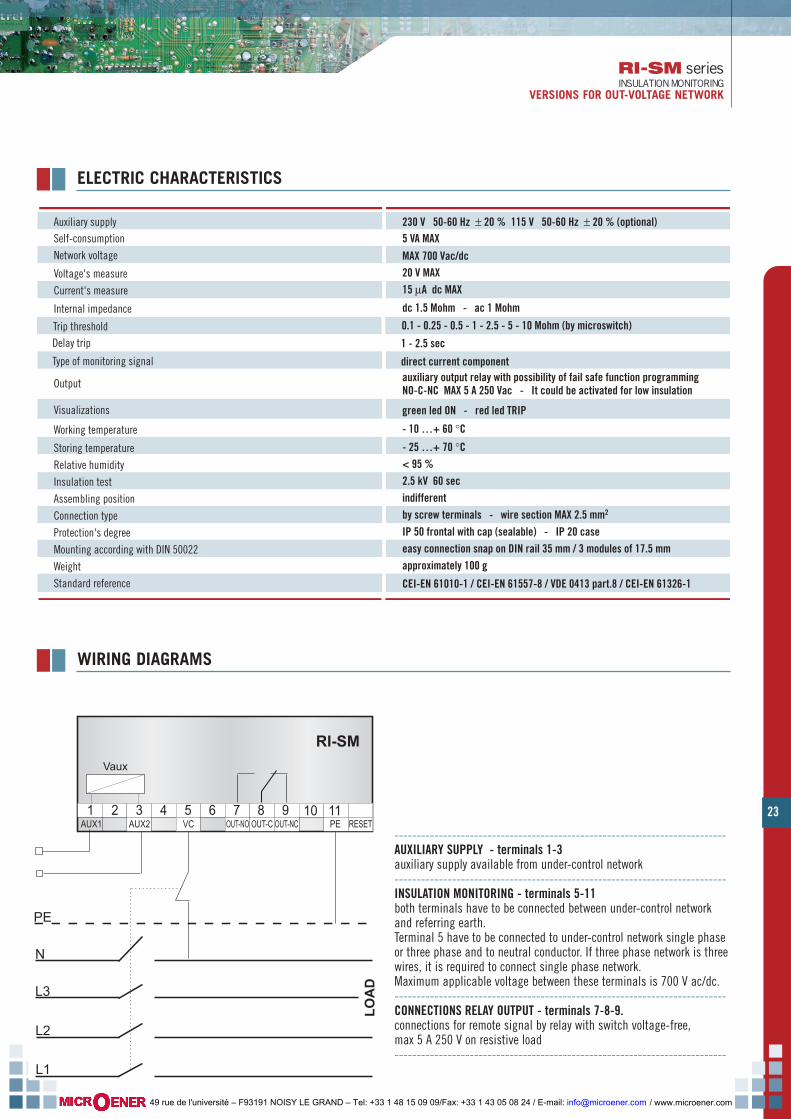
Auxiliary supply 230 V 50-60 Hz ± 20 % 115 V 50-60 Hz ± 20 % (optional)Self-consumption 5 VA MAX Network voltage
20 V MAXVoltage's measure15 µA dc MAXCurrent's measure
dc 1.5 Mohm - ac 1 MohmInternal impedance
1 - 2.5 secDelay trip
direct current componentType of monitoring signal
- 10 …+ 60 °CWorking temperature
- 25 …+ 70 °CStoring temperature< 95 %Relative humidity2.5 kV 60 secInsulation testindifferentAssembling positionby screw terminals - wire section MAX 2.5 mm2Connection typeIP 50 frontal with cap (sealable) - IP 20 caseProtection's degreeeasy connection snap on DIN rail 35 mm / 3 modules of 17.5 mmMounting according with DIN 50022approximately 100 gWeight
CEI-EN 61010-1 / CEI-EN 61557-8 / VDE 0413 part.8 / CEI-EN 61326-1Standard reference
MAX 700 Vac/dc
auxiliary output relay with possibility of fail safe function programmingNO-C-NC MAX 5 A 250 Vac - It could be activated for low insulation
Output
0.1 - 0.25 - 0.5 - 1 - 2.5 - 5 - 10 Mohm (by microswitch)Trip threshold
green led ON - red led TRIPVisualizations
ELECTRIC CHARACTERISTICS
1 2 3 4 5 6 7 8 9PE
10 11 12
RI-SM
AUX1
LOAD
L1
OUT-NO OUT-NCOUT-CAUX2 VC RESET
Vaux
PE
L2
L3
N
WIRING DIAGRAMS
---------------------------------------------------------------------------AUXILIARY SUPPLY - terminals 1-3auxiliary supply available from under-control network---------------------------------------------------------------------------INSULATION MONITORING - terminals 5-11both terminals have to be connected between under-control networkand referring earth.Terminal 5 have to be connected to under-control network single phaseor three phase and to neutral conductor. If three phase network is threewires, it is required to connect single phase network.Maximum applicable voltage between these terminals is 700 V ac/dc.---------------------------------------------------------------------------CONNECTIONS RELAY OUTPUT - terminals 7-8-9.connections for remote signal by relay with switch voltage-free,max 5 A 250 V on resistive load---------------------------------------------------------------------------
/ www.microener.com 49 rue de l'université – F93191 NOISY LE GRAND – Tel: +33 1 48 15 09 09/Fax: +33 1 43 05 08 24 / E-mail: [email protected]
HRI seriesINSULATION MONITORINGVERSIONS FOR USE IN MEDICAL ROOMS
24
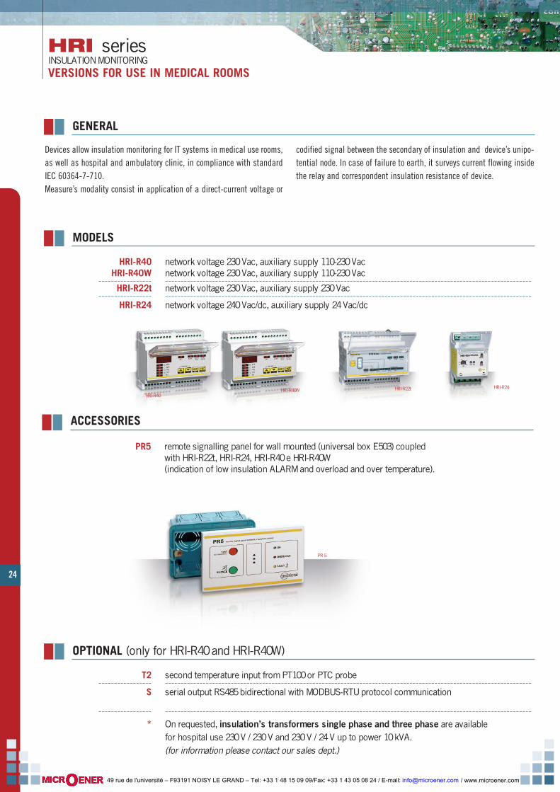
Devices allow insulation monitoring for IT systems in medical use rooms,as well as hospital and ambulatory clinic, in compliance with standardIEC 60364-7-710.Measure’s modality consist in application of a direct-current voltage or
codified signal between the secondary of insulation and device’s unipo-tential node. In case of failure to earth, it surveys current flowing insidethe relay and correspondent insulation resistance of device.
MODELS
GENERAL
HRI-R40 network voltage 230 Vac, auxiliary supply 110-230 VacHRI-R40W network voltage 230 Vac, auxiliary supply 110-230 Vac
----------------- ---------------------------------------------------------------------------------------------------------------------HRI-R22t network voltage 230 Vac, auxiliary supply 230 Vac
----------------- ---------------------------------------------------------------------------------------------------------------------HRI-R24 network voltage 240 Vac/dc, auxiliary supply 24 Vac/dc
ACCESSORIES
OPTIONAL (only for HRI-R40 and HRI-R40W)
T2 second temperature input from PT100 or PTC probe----------------- ---------------------------------------------------------------------------------------------------------------------
S serial output RS485 bidirectional with MODBUS-RTU protocol communication
----------------- ---------------------------------------------------------------------------------------------------------------------* On requested, insulation’s transformers single phase and three phase are available
for hospital use 230 V / 230 V and 230 V / 24 V up to power 10 kVA.(for information please contact our sales dept.)
HRI-R24HRI-R22tHRI-R40
HRI-R40W
PR5 remote signalling panel for wall mounted (universal box E503) coupledwith HRI-R22t, HRI-R24, HRI-R40 e HRI-R40W (indication of low insulation ALARM and overload and over temperature).
PR 5
/ www.microener.com 49 rue de l'université – F93191 NOISY LE GRAND – Tel: +33 1 48 15 09 09/Fax: +33 1 43 05 08 24 / E-mail: [email protected]
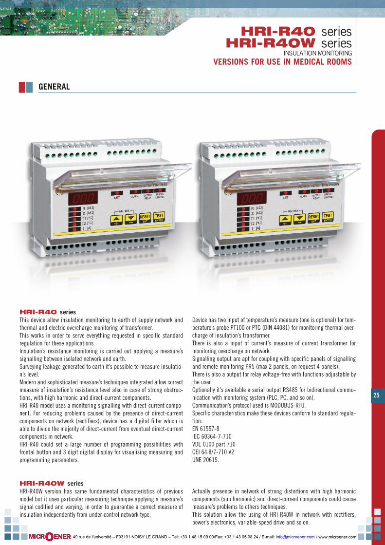
25
HRI-R40 seriesHRI-R40W series
INSULATION MONITORINGVERSIONS FOR USE IN MEDICAL ROOMS
GENERAL
HRI-R40 seriesThis device allow insulation monitoring to earth of supply network andthermal and electric overcharge monitoring of transformer. This works in order to serve everything requested in specific standardregulation for these applications.Insulation’s resistance monitoring is carried out applying a measure’ssignalling between isolated network and earth.Surveying leakage generated to earth it’s possible to measure insulatio-n’s level.Modern and sophisticated measure’s techniques integrated allow correctmeasure of insulation’s resistance level also in case of strong obstruc-tions, with high harmonic and direct-current components.HRI-R40 model uses a monitoring signalling with direct-current compo-nent. For reducing problems caused by the presence of direct-currentcomponents on network (rectifiers), device has a digital filter which isable to divide the majority of direct-current from eventual direct-currentcomponents in network.HRI-R40 could set a large number of programming possibilities withfrontal button and 3 digit digital display for visualising measuring andprogramming parameters.
Device has two input of temperature’s measure (one is optional) for tem-perature’s probe PT100 or PTC (DIN 44081) for monitoring thermal over-charge of insulation’s transformer.There is also a input of current’s measure of current transformer formonitoring overcharge on network.Signalling output are apt for coupling with specific panels of signallingand remote monitoring PR5 (max 2 panels, on request 4 panels).There is also a output for relay voltage-free with functions adjustable bythe user.Optionally it’s available a serial output RS485 for bidirectional commu-nication with monitoring system (PLC, PC, and so on).Communication’s protocol used is MODUBUS-RTU.Specific characteristics make these devices conform to standard regula-tion:EN 61557-8IEC 60364-7-710VDE 0100 part 710CEI 64.8/7-710 V2UNE 20615.
HRI-R40W seriesHRI-R40W version has same fundamental characteristics of previousmodel but it uses particular measuring technique applying a measure’ssignal codified and varying, in order to guarantee a correct measure ofinsulation independently from under-control network type.
Actually presence in network of strong distortions with high harmoniccomponents (sub harmonic) and direct-current components could causemeasure’s problems to others techniques.This solution allow the using of HRI-R40W in network with rectifiers,power’s electronics, variable-speed drive and so on.
/ www.microener.com 49 rue de l'université – F93191 NOISY LE GRAND – Tel: +33 1 48 15 09 09/Fax: +33 1 43 05 08 24 / E-mail: [email protected]

26
HRI-R40 seriesHRI-R40W seriesINSULATION MONITORINGVERSIONS FOR USE IN MEDICAL ROOMS
FUNCTIONS AND OPERATORS - LEGEND
------------------------------------------------------------------------------------1 display for visualising under-control parameters’ degree and for
visualising settings------------------------------------------------------------------------------------
2 green LED SET for indication of programming status ------------------------------------------------------------------------------------
3 yellow LED ALARM for indication alarm for parameter’sdegree out-threshold------------------------------------------------------------------------------------
4 red LED OUTPUT RELAY for indication status of auxiliary relay output------------------------------------------------------------------------------------
5 red LED ERROR / LINK FAIL for indication alarm of internal failure,lack connection to under-control network, temperature’s probePT100 open or short circuit------------------------------------------------------------------------------------
6 red LED R for indication visualisation of insulation’s resistanceparameter; flashing light for out-threshold parameter------------------------------------------------------------------------------------
7 red LED Z for indication visualisation of insulation’s impedanceparameter; flashing light for out-threshold parameter.------------------------------------------------------------------------------------
8 red LED T1 for indication visualisation parameter of transformer’stemperature; flashing light for out-threshold parameter.------------------------------------------------------------------------------------
9 red LED T2 for indication visualisation parameter of second sensortemperature; flashing light for out-threshold parameter.------------------------------------------------------------------------------------
10 red LED I for indication visualisation current of network parameter;flashing light for out-threshold parameter.------------------------------------------------------------------------------------
11 button +/- UP/DOWN for selecting parameter that has to bevisualised, for regulating device’s setting and for visualisingmaximum and minimum memorized degrees------------------------------------------------------------------------------------
12 button RESET / SET for entering device’s programming, for stoppingalarms and memorized degrees resetting------------------------------------------------------------------------------------
13 button TEST / ENTER for testing device and remote signalling panelsand for confirming SETUP settings------------------------------------------------------------------------------------
insulation monitor HRI-R40
ALARM OUTPUTRELAY
ERROR /LINK FAIL
SET
TESTRESET
MIN / MAX
ENTERSET+_
contrelcontrel
R
Z
T1
T2
I
[k ]Ω[k ]Ω[°C]
[°C]
[A]
11
22 33 44 55
1111 1122 1133
66
77
88
99
1100
insulation monitor HRI-R40
ALARM OUTPUTRELAY
ERROR /LINK FAIL
SET
TESTRESET
MIN / MAX
ENTERSET+_
contrelcontrel
R
Z
T1
T2
I
[k ]Ω[k ]Ω[°C]
[°C]
[A]
105
90
74
68
44
45
DIMENSIONS
HRI-R40 / HRI-R40W
/ www.microener.com 49 rue de l'université – F93191 NOISY LE GRAND – Tel: +33 1 48 15 09 09/Fax: +33 1 43 05 08 24 / E-mail: [email protected]
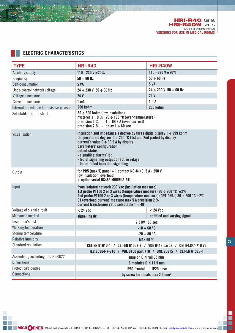
27
HRI-R40 seriesHRI-R40W series
INSULATION MONITORINGVERSIONS FOR USE IN MEDICAL ROOMS
2.5 KV 60 sec-10 ÷ 60 °C-20 ÷ 80 °CMAX 90 %
CEI-EN 61010-1 / CEI-EN 61557-8 / VDE 0413 part.8 / CEI 64.8/7-710 V2IEC 60364-7-710 / VDE 0100 part.710 / UNE 20615 / CEI-EN 61326-1
snap on DIN rail 35 mm 6 modules DIN 17.5 mm
IP50 frontal - IP20 caseby screw terminals max 2.5 mm2
Internal impedance for resistive measureSelectable trip threshold
Visualisation
Output
Input
Voltage of signal circuitMeasure’s method Insulation’s testWorking temperatureStoring temperatureRelative humidityStandard regulation
Assembling according to DIN 50022DimensionsProtection’s degreeConnections
200 kohm 50 ÷ 500 kohm (low insulation) hysteresis 10 % 20 ÷ 180 °C (over-temperature)precision 2 % - 1 ÷ 99.9 A (over-current)precision 2 % - delay 1 ÷ 60 sec
insulation and impedance’s degree by three digits display 1 ÷ 999 kohmtemperature’s degree 0 ÷ 200 °C (1st and 2nd probe) by displaycurrent’s value 0 ÷ 99.9 A by displayparameters’ configurationoutput status:- signalling alarms’ led - led of signalling output of active relays- led of failed insertion signalling
for PR5 (max 5) panel + 1 contact NO-C-NC 5 A - 250 V low insulation, overload+ option serial RS485 MODBUS-RTU
from isolated network 230 Vac (insulation measure)1st probe PT100 2 or 3 wires (temperature measure) 30 ÷ 200 °C ±2%2nd probe PT100 2 or 3 wires (temperature measure) (OPTIONAL) 30 ÷ 200 °C ±2%CT (overload current’ measure max 5 A precision 2 %current transformer ratio selectable 1 ÷ 40< 24 Vdcsignalling dc
TYPE HRI-R40 HRI-R40WAuxiliary supplyFrequencySelf-consumptionUnde-control network voltageVoltage's measure Current's measure
110 - 230 V ±20%50 ÷ 60 Hz5 VA24 ÷ 230 V 50 ÷ 60 Hz24 V1 mA
110 - 230 V ±20%50 ÷ 60 Hz5 VA24 ÷ 230 V 50 ÷ 60 Hz24 V1 mA200 kohm
< 24 Vdccodified and varying signal
ELECTRIC CHARACTERISTICS
/ www.microener.com 49 rue de l'université – F93191 NOISY LE GRAND – Tel: +33 1 48 15 09 09/Fax: +33 1 43 05 08 24 / E-mail: [email protected]
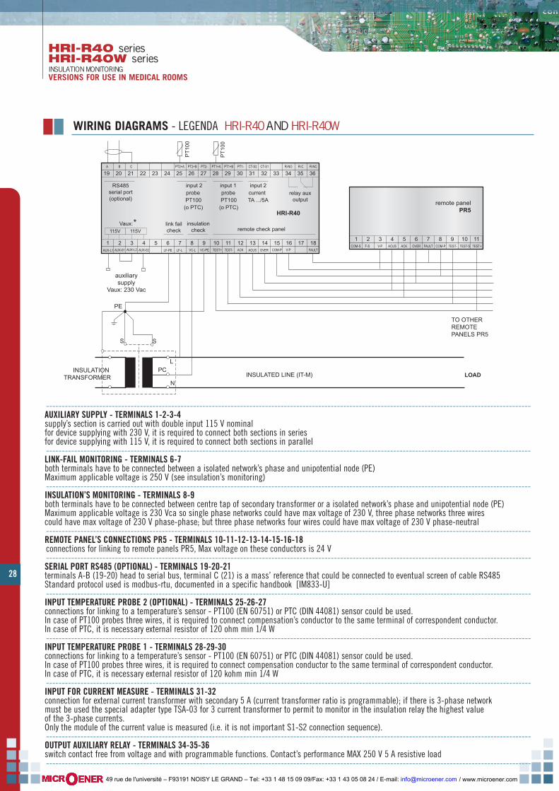
28
LF-PE
1 2 3 4 5 6 7 8 9 10 11 12 13 14 15 16 17 18LF-L VC-L VC-PEAUX-L1 AUX-01 AUX-02AUX-L2 TEST+ TEST- ACK ACUS OVER COM-P V-P FAULT
Vaux:*remote check panel
19 20 21 22 23 24 25 26 27 28 29 30 31 32 33 34 35 36PT2+AA B C PT2+B PT2- PT1+A PT1+B PT1- CT-S2 CT-S1 R-NO R-C R-NC
RS485serial port(optional)
input 2probePT100(o PTC)
input 1probePT100
(o PTC)
input 2currentTA .../5A
relay auxoutput
HRI-R40
1 2 3 4 5 6 7 8 9TEST+TEST-
10 11ACKACUS OVER COM-PV-P FAULT
PE
PC
SS
INSULATED LINE (IT-M) LOADINSULATION
TRANSFORMER
auxiliarysupply
Vaux: 230 Vac
115V 115V
L
N
TO OTHER REMOTE PANELS PR5
PT1
00
PT1
00
COM-S F-S TEST-S
insulationcheck
link failcheck
remote panelPR5
WIRING DIAGRAMS - LEGENDA HRI-R40AND HRI-R40W
-----------------------------------------------------------------------------------------------------------------------------------------------------------AUXILIARY SUPPLY - TERMINALS 1-2-3-4supply’s section is carried out with double input 115 V nominalfor device supplying with 230 V, it is required to connect both sections in seriesfor device supplying with 115 V, it is required to connect both sections in parallel-----------------------------------------------------------------------------------------------------------------------------------------------------------LINK-FAIL MONITORING - TERMINALS 6-7both terminals have to be connected between a isolated network’s phase and unipotential node (PE)Maximum applicable voltage is 250 V (see insulation’s monitoring)-----------------------------------------------------------------------------------------------------------------------------------------------------------INSULATION’S MONITORING - TERMINALS 8-9both terminals have to be connected between centre tap of secondary transformer or a isolated network’s phase and unipotential node (PE)Maximum applicable voltage is 230 Vca so single phase networks could have max voltage of 230 V, three phase networks three wirescould have max voltage of 230 V phase-phase; but three phase networks four wires could have max voltage of 230 V phase-neutral-----------------------------------------------------------------------------------------------------------------------------------------------------------REMOTE PANEL’S CONNECTIONS PR5 - TERMINALS 10-11-12-13-14-15-16-18connections for linking to remote panels PR5, Max voltage on these conductors is 24 V-----------------------------------------------------------------------------------------------------------------------------------------------------------SERIAL PORT RS485 (OPTIONAL) - TERMINALS 19-20-21terminals A-B (19-20) head to serial bus, terminal C (21) is a mass’ reference that could be connected to eventual screen of cable RS485Standard protocol used is modbus-rtu, documented in a specific handbook [IM833-U]-----------------------------------------------------------------------------------------------------------------------------------------------------------INPUT TEMPERATURE PROBE 2 (OPTIONAL) - TERMINALS 25-26-27connections for linking to a temperature’s sensor - PT100 (EN 60751) or PTC (DIN 44081) sensor could be used.In case of PT100 probes three wires, it is required to connect compensation’s conductor to the same terminal of correspondent conductor.In case of PTC, it is necessary external resistor of 120 ohm min 1/4 W-----------------------------------------------------------------------------------------------------------------------------------------------------------INPUT TEMPERATURE PROBE 1 - TERMINALS 28-29-30connections for linking to a temperature’s sensor - PT100 (EN 60751) or PTC (DIN 44081) sensor could be used.In case of PT100 probes three wires, it is required to connect compensation conductor to the same terminal of correspondent conductor.In case of PTC, it is necessary external resistor of 120 kohm min 1/4 W-----------------------------------------------------------------------------------------------------------------------------------------------------------INPUT FOR CURRENT MEASURE - TERMINALS 31-32connection for external current transformer with secondary 5 A (current transformer ratio is programmable); if there is 3-phase networkmust be used the special adapter type TSA-03 for 3 current transformer to permit to monitor in the insulation relay the highest valueof the 3-phase currents.Only the module of the current value is measured (i.e. it is not important S1-S2 connection sequence).-----------------------------------------------------------------------------------------------------------------------------------------------------------OUTPUT AUXILIARY RELAY - TERMINALS 34-35-36switch contact free from voltage and with programmable functions. Contact’s performance MAX 250 V 5 A resistive load-----------------------------------------------------------------------------------------------------------------------------------------------------------
HRI-R40 seriesHRI-R40W seriesINSULATION MONITORINGVERSIONS FOR USE IN MEDICAL ROOMS
/ www.microener.com 49 rue de l'université – F93191 NOISY LE GRAND – Tel: +33 1 48 15 09 09/Fax: +33 1 43 05 08 24 / E-mail: [email protected]
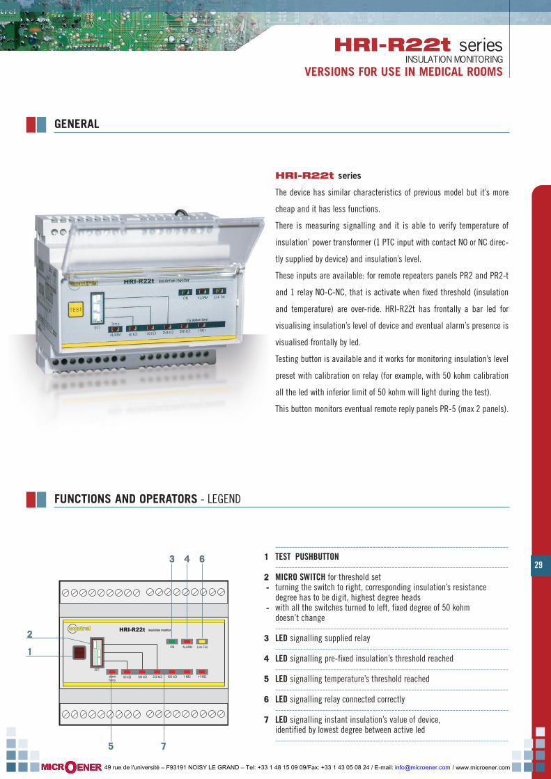
29
HRI-R22t seriesINSULATION MONITORING
VERSIONS FOR USE IN MEDICAL ROOMS
GENERAL
HRI-R22t series
The device has similar characteristics of previous model but it’s more
cheap and it has less functions.
There is measuring signalling and it is able to verify temperature of
insulation’ power transformer (1 PTC input with contact NO or NC direc-
tly supplied by device) and insulation’s level.
These inputs are available: for remote repeaters panels PR2 and PR2-t
and 1 relay NO-C-NC, that is activate when fixed threshold (insulation
and temperature) are over-ride. HRI-R22t has frontally a bar led for
visualising insulation’s level of device and eventual alarm’s presence is
visualised frontally by led.
Testing button is available and it works for monitoring insulation’s level
preset with calibration on relay (for example, with 50 kohm calibration
all the led with inferior limit of 50 kohm will light during the test).
This button monitors eventual remote reply panels PR-5 (max 2 panels).
contrelcontrel
50 kΩ
TEST
HRI-R22t insulation monitor
100 kΩ 250 kΩ 500 kΩ 1 MΩalarmTemp.
>1 MΩ
Link FailALARMON
SET
11
33 44 66
55 77
22
FUNCTIONS AND OPERATORS - LEGEND
------------------------------------------------------------------------------------11 TEST PUSHBUTTON
------------------------------------------------------------------------------------22 MICRO SWITCH for threshold set-- turning the switch to right, corresponding insulation’s resistance
degree has to be digit, highest degree heads-- with all the switches turned to left, fixed degree of 50 kohm
doesn’t change------------------------------------------------------------------------------------
33 LED signalling supplied relay------------------------------------------------------------------------------------
44 LED signalling pre-fixed insulation’s threshold reached------------------------------------------------------------------------------------
55 LED signalling temperature’s threshold reached------------------------------------------------------------------------------------
66 LED signalling relay connected correctly------------------------------------------------------------------------------------
77 LED signalling instant insulation’s value of device,identified by lowest degree between active led------------------------------------------------------------------------------------
/ www.microener.com 49 rue de l'université – F93191 NOISY LE GRAND – Tel: +33 1 48 15 09 09/Fax: +33 1 43 05 08 24 / E-mail: [email protected]

30
HRI-R22t seriesINSULATION MONITORINGVERSIONS FOR MEDICAL USE ROOMS
Internal impedance for resistive measureSelectable trip threshold
Visualisation
Output
Input
Voltage of signal circuitMeasure’s method Insulation’s testWorking temperatureStoring temperatureRelative humidityStandard regulation
Assembling according to DIN 50022DimensionsProtection’s degreeConnections
1 Mohm50-100-250 kohm (low insulation) by switches
led of insulation value by led bar 50 ÷ 1000 kohmled of signalling network’s presenceled of signalling low insulationled of signalling over-temperatureled of failed insertion signalling
for panel PR5 (max 2) total+ 1 contact NO-C-NC 5 A - 250 V (low insulation)+ 1 contact NO-C-NC 5 A - 250 V (over-temperature )
from isolated network 230 Vac (insulation measure)PTC probe (temperature measurement)
< 24 Vdcsignalling dc2.5 kV 60 sec-10 ÷ 60 °C-20 ÷ 80 °CMAX 90 %CEI-EN 61010-1 / CEI-EN 61557-8 / VDE 0413 part.8CEI 64.8/7-710 V2 / IEC 60364-7-710 / UNE 20615 / CEI-EN 61326-1snap on DIN rail 35 mm 6 modules DIN 17.5 mmIP50 frontal - IP20 caseby screw terminals max 2.5 mm2
TYPE HRI-R22tAuxiliary supplyFrequencySelf-consumptionUnde-control network voltageVoltage's measure Current's measure
230 V ± 20%50 ÷ 60 Hz3 VA24 ÷ 230 V 50 ÷ 60 Hz< 15 V< 0.6 mA
ELECTRIC CHARACTERISTICS
contrelcontrel
50 kΩ
TEST
HRI-R22t insulation monitor
100 kΩ 250 kΩ 500 kΩ 1 MΩalarmTemp.
>1 MΩ
Link FailALARMON
SET
105
90
58
DIMENSIONS
/ www.microener.com 49 rue de l'université – F93191 NOISY LE GRAND – Tel: +33 1 48 15 09 09/Fax: +33 1 43 05 08 24 / E-mail: [email protected]
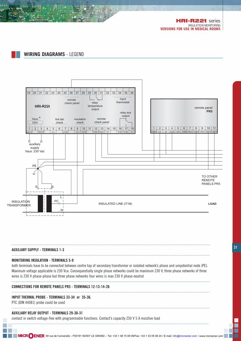
31
HRI-R22t seriesINSULATION MONITORING
VERSIONS FOR USE IN MEDICAL ROOMS
WIRING DIAGRAMS - LEGEND
---------------------------------------------------------------------------------------------------------------------------------------------------AUXILIARY SUPPLY - TERMINALS 1-3---------------------------------------------------------------------------------------------------------------------------------------------------MONITORING INSULATION - TERMINALS 5-9both terminals have to be connected between centre tap of secondary transformer or isolated network’s phase and unipotential node (PE). Maximum voltage applicable is 230 Vca. Consequentially single phase networks could be maximum 230 V, three phase networks of threewires is 230 V phase-phase but three phase networks four wires is max 230 V phase-neutral---------------------------------------------------------------------------------------------------------------------------------------------------CONNECTIONS FOR REMOTE PANELS PR5 - TERMINALS 12-13-14-26---------------------------------------------------------------------------------------------------------------------------------------------------INPUT THERMAL PROBE - TERMINALS 33-34 or 35-36. PTC (DIN 44081) probe could be used---------------------------------------------------------------------------------------------------------------------------------------------------AUXILIARY RELAY OUTPUT - TERMINALS 29-30-31contact in switch voltage-free with programmable functions. Contact’s capacity 250 V 5 A resistive load--------------------------------------------------------------------------------------------------------------------------------------------------
INSULATION TRANSFORMER
auxiliarysupply
Vaux: 230 Vac
LF-PE1 2 3 4 5 6 7 8 9 10 11 12 13 14 15 16 17 18
LF-L VC-L VC-PEAUX-L1 AUX-01 COM-P V-PFAULT
Vaux:*
19 20 21 22 23 24 25 26 27 28 29 30 31 32 33 34 35 36
HRI-R22t
1 2 3 4 5 6 7 8 9TEST+TEST-
10 11ACKACUS OVER COM-PV-P FAULT
remote panelPR5
230V
COM-S F-S TEST-SR-NO R-CR-NC
inputthermostat
PE
PC
SS
INSULATED LINE (IT-M) LOAD
L
N
TO OTHER REMOTE PANELS PR5
link failcheck
insulationcheck
remote check panel
remote check panel
relay auxoutput
relay temperature
output
/ www.microener.com 49 rue de l'université – F93191 NOISY LE GRAND – Tel: +33 1 48 15 09 09/Fax: +33 1 43 05 08 24 / E-mail: [email protected]
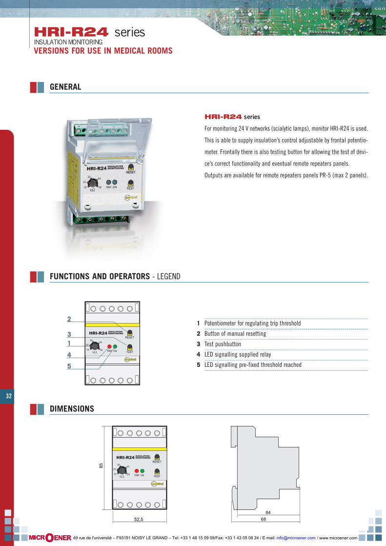
32
HRI-R24 seriesINSULATION MONITORINGVERSIONS FOR USE IN MEDICAL ROOMS
GENERAL
HRI-R24 series
For monitoring 24 V networks (scialytic lamps), monitor HRI-R24 is used.
This is able to supply insulation’s control adjustable by frontal potentio-
meter. Frontally there is also testing button for allowing the test of devi-
ce’s correct functionality and eventual remote repeaters panels.
Outputs are available for remote repeaters panels PR-5 (max 2 panels).
ONTRIP TEST
RESET
connttrreellcontrelconnttrreellcontrel
10
20
3040
50
INSULATIONMONITORINGHRI-R24
kΩ
FUNCTIONS AND OPERATORS - LEGEND
------------------------------------------------------------------------------------11 Potentiometer for regulating trip threshold
------------------------------------------------------------------------------------22 Button of manual resetting
------------------------------------------------------------------------------------33 Test pushbutton
------------------------------------------------------------------------------------44 LED signalling supplied relay
------------------------------------------------------------------------------------55 LED signalling pre-fixed threshold reached
------------------------------------------------------------------------------------
22
3311
44
55
64
68
85
ONTRIP TEST
RESET
connttrreellcontrelconnttrreellcontrel
52,5
10
20
3040
50
INSULATIONMONITORINGHRI-R24
kΩ
DIMENSIONS
/ www.microener.com 49 rue de l'université – F93191 NOISY LE GRAND – Tel: +33 1 48 15 09 09/Fax: +33 1 43 05 08 24 / E-mail: [email protected]

33
HRI-R24 seriesINSULATION MONITORING
VERSIONS FOR USE IN MEDICAL ROOMS
1 2 3 4 5 6 7 8 9PE
10V-
insulation checkHRI-R24
V+
PE
SS
INSULATED LINE 24V ca/cc LOAD
INSULATION TRANSFORMER
L(+)
N(-)
1 2 3 4 5 6 7 8 9
TO OTHER REMOTE PANELS PR5
OUT-NO OUT-NCOUT-C10 11
TEST+TEST-ACKACUS OVER COM-PV-P FAULTCOM-S F-S TEST-S
remote panelPR5
ELECTRIC CHARACTERISTICS
WIRING DIAGRAMS - LEGEND
Auxiliary supplyFrequencySelf-consumptionUnde-control network voltageCurrent's measureInternal impedance for resistive measureInternal impedance for resistive measureVisualisation
24 Vdc/ac -20 % +10 % 50 ÷ 60 Hz3 W24 Vdc/ac 50 ÷ 60 Hz< 0.5 mA50 kohm10 ÷ 50 kohm (by potentiometer)
TYPE HRI-R24
from isolated network 240 Vac/dc (insulation measure)Input< 24 Vdcvariation of polarity’s potential2.5 kV 60 sec-10 ÷ 60 °C-20 ÷ 80 °CMAX 90 %CEI-EN 61010-1 / CEI-EN 61557-8 / VDE 0413 part.8 CEI 64.8/7-710 V2 / IEC 60364-7-710 / UNE 20615 / CEI-EN 61326-1snap on DIN rail 35 mm 3 modules DIN 17.5 mmIP50 frontal - IP20 caseby screw terminals max 2.5 mm2
led of signalling network’s presenceled of signalling low insulationfor PR5 panel (max 2)Output
Voltage of signal circuitMeasure’s method Insulation’s testWorking temperatureStoring temperatureRelative humidityStandard regulation
Assembling according to DIN 50022DimensionsProtection’s degreeConnections
/ www.microener.com 49 rue de l'université – F93191 NOISY LE GRAND – Tel: +33 1 48 15 09 09/Fax: +33 1 43 05 08 24 / E-mail: [email protected]
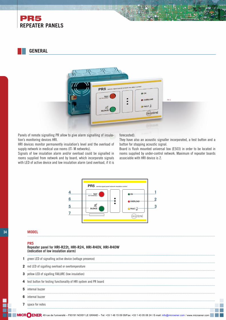
34
PR5REPEATER PANELS
PR5 remote signal panel network insulation control
ON
FAULT
TESTTEST PERIODICALLY
SILENCE
OVERLOAD
GENERAL
44
66
55
11
22
33
77
MODEL---------------------------------------------------------------------------------------------------------------------------------------------------------------------
PR5Repeater panel for HRI-R22t, HRI-R24, HRI-R40V, HRI-R40W (indication of low insulation alarm)---------------------------------------------------------------------------------------------------------------------------------------------------------------------
11 green LED of signalling active device (voltage presence)---------------------------------------------------------------------------------------------------------------------------------------------------------------------
22 red LED of sigalling overload or overtemperature---------------------------------------------------------------------------------------------------------------------------------------------------------------------
33 yellow LED of sigalling FAILURE (low insulation)---------------- -----------------------------------------------------------------------------------------------------------------------------------------------------
44 test button for testing functionality of HRI system and PR board---------------------------------------------------------------------------------------------------------------------------------------------------------------------
55 internal buzzer---------------------------------------------------------------------------------------------------------------------------------------------------------------------
66 internal buzzer---------------------------------------------------------------------------------------------------------------------------------------------------------------------
77 space for notes---------------------------------------------------------------------------------------------------------------------------------------------------------------------
Panels of remote signalling PR allow to give alarm signalling of insula-tion’s monitoring devices HRI.HRI devices monitor permanently insulation’s level and the overload ofsupply network in medical use rooms (IT- M networks).Signals of low insulation alarm and/or overload could be signalled inrooms supplied from network and by board, which incorporate signalswith LED of active device and low insulation alarm (and overload, if it is
forecasted).They have also an acoustic signaller incorporated, a test button and abutton for stopping acoustic signal.Board is flush mounted universal box (E503) in order to be located inrooms supplied by under-control network. Maximum of repeater boardsassociable with HRI device is 2.
PR 5
/ www.microener.com 49 rue de l'université – F93191 NOISY LE GRAND – Tel: +33 1 48 15 09 09/Fax: +33 1 43 05 08 24 / E-mail: [email protected]

PR5 remote signal panel network insulation control
ON
E503
FAULT
TESTTEST PERIODICALLY
SILENCE
OVERLOAD79
123 7 13 15
35
MOUNTING SEQUENCEWIRING
PR2-PR2t-PR4REPEATER PANELS
Operative voltage 12 - 24 Vac/dc (from HRI device)
- 10 …+ 60 °CWorking temperature
- 25 …+ 80 °CStoring temperature
MAX 95 %Relative humidity2.5 kVrms 50 Hz for 60 secInsulation test
by screw terminals - wire section MAX 2.5 mm2Connection type
IP 30 front panel - IP 20 caseProtection's degree
universal flush-mount box E503Mounting
approximately 200 gWeightCEI-EN 61010-1 | CEI-EN 61557-8 / VDE 0413 part.8 CEI 64.8/7-710 V2/ IEC 60364-7-710 / UNE 20615 | CEI-EN 61326-1Standard reference
green led NETWORK - red led ALARM of overloadyellow led ALARM of FAILURE low insulation, acoustic signal
Signallings
test button - stopping acoustic signal buttonOperators
ELECTRIC CHARACTERISTICS
DIMENSIONS
ASSEMBLING PANEL’S CONNECTIONS
/ www.microener.com 49 rue de l'université – F93191 NOISY LE GRAND – Tel: +33 1 48 15 09 09/Fax: +33 1 43 05 08 24 / E-mail: [email protected]

EML-12SSERIAL REMOTE CONCENTRATORFOR REMOTE MONITORING OF NETWORK’S PARAMETERS
36
Serial remote concentrator is a device which allow remote monitoring ofparameters originated from insulation’s supervisors for medical userooms HRI-R40 and HRI-R40W with serial output RS485.By serial communication RS485 Modbus-RTU protocol different supervi-sors are connected to concentrator EML-12S.Device could supply degrees of insulation and impedance’s resistance, ofnetwork’s temperature and current, and eventual alarm’s presence with
data-logger function.By its time, device could be connected to a PC and transmit differentparameters gathered. It could also be connected to a remote visualisa-tion panel with function of signalling alarms in network.
GENERAL
HRI NETWORK
contrel
HRI NETWORK
HRIHRIHRIHRIHRI
RS485MODBUS
PC VISUAL DISPLAY
RS48
5MOD
BUS RS485M
ODBUS
MODELS-------- ---------------------------------------------------------------------------EML-12 remote concentrator Vaux 24 Vdc/ac-------- ---------------------------------------------------------------------------
Devices HRI-R40 or HRI-R40W are connected to EML-12S concentrator by serial output RS485. Maximum 12 HRI devices could be connected
/ www.microener.com 49 rue de l'université – F93191 NOISY LE GRAND – Tel: +33 1 48 15 09 09/Fax: +33 1 43 05 08 24 / E-mail: [email protected]

37
EML-12SSERIAL REMOTE CONCENTRATOR
FOR REMOTE MONITORING OF NETWORK’S PARAMETERS
For every device connected it’s possible tovisualiseINSULATION’S RESISTANCE,IMPEDANCE,TEMPERATURES AND CURRENTS.
VISUALISATION
For every device connected it’s possible tovisualise instrument’s status
ON = (online)OFF (offline).
For every instrumentit’s possible to visualiselast 4 intervened alarms.
EVENTSWhen there is an alarm,
it’s automatically visualised on display withindication of total alarms active
in that moment.
MENU AND SETTINGSBy menu, it’s possible to set parameters
as date and hour, language,
number of connected devices and settings for serial communication.
/ www.microener.com 49 rue de l'université – F93191 NOISY LE GRAND – Tel: +33 1 48 15 09 09/Fax: +33 1 43 05 08 24 / E-mail: [email protected]

RI_
HR
I-U
K-0
4 -
© C
ontr
el e
lettr
onic
a - a
ll rig
hts
rese
rved
- en
d pr
int o
ctob
er 2
010
ISO 9001:20089105-C035
industrial applications
/ www.microener.com 49 rue de l'université – F93191 NOISY LE GRAND – Tel: +33 1 48 15 09 09/Fax: +33 1 43 05 08 24 / E-mail: [email protected]
According to the copyright and the civil
law,the reproduction of this catalogue, or
any part of this one, by electronic, mecha-
nical methods, by means of photocopies,
microfilms, recordings or other, is perem-
ptorily forbidden. Rights are reserved for
all countries.
Drawings, specifications and reference
numbers may be modified and changed.
CONTREL s.r.l reserves itself the right, to
make changes for technical or quality
improvements, without any notice.


![Motor Insulation Health Monitoring 20SEP2013 · monitoring of insulation health condition and its degradation in a continuous manner [8], which is a major breakthrough in the area](https://static.fdocuments.net/doc/165x107/5ed8f87e6714ca7f4768e8d0/motor-insulation-health-monitoring-20sep2013-monitoring-of-insulation-health-condition.jpg)