INSTRUMENTS AND CONTROLS -...
23
INSTRUMENTS AND CONTROLS 21. Draft or position switch-over lever 22. P.T.O. control lever Before attempting to operate your new tractor, become 23. Independent to synchronous P.T.O. control familiar with the location and purpose of its controls 24. Gear shift lever and instruments. Additional information will be found 25. Brake lock rod on the control or instrument. 26. Front wheel drive control rod (520) 1. Ammeter 10. High beam dimmer switch 27. Differential lock 2. Engine oil pressure 11. High beam indicator light 28. Hydraulic pump, engageidisengage lever 3. TachometeriHourmeter 12. Fuse box 29. Brake pedals 4. Water temperature gauge 13. Rad shutter control 30. Brake latch 5. Glow plug indicator 14. Operat or seat 31. Clutch pedal 6. Ignition key switch 15. 16. 17. Hydraulic control levers 32. Foot Throttle 7. Ground switch 18. Traction Booster lever 33. Hand Throttle 36. Ground switch indicator light 8. Turn signal light switch 19. Traction booster control valve 34. Light switch 37. Draft control ajustable stop 9. Turn indicator light 20. Draft control lever 35. Dash light 38. Draft control neutral stou Fig. 2 Instruments and controls
Transcript of INSTRUMENTS AND CONTROLS -...

INSTRUMENTS AND CONTROLS 21. Draft or position switch-over lever
22. P.T.O. control lever Before at tempting to operate your n e w tractor , become 23. Independent to synchronous P.T.O. control familiar wi th the location a n d purpose of i t s controls 24. G e a r shift lever a n d instruments . Addit ional information will be found 25. Brake lock rod on the control o r instrument . 26. Front wheel dr ive control rod (520) 1. Ammeter 10. High beam dimmer switch 27. Differential lock 2. Engine oil pressure 11. High beam indicator light 28. Hydraul ic pump, engageidisengage lever 3. TachometeriHourmeter 12. Fuse box 29. Brake pedals 4. Water temperature g a u g e 13. Rad shut ter control 30. Brake latch 5. Glow plug indicator 14. Operat or seat 31. Clutch pedal 6. Ignition key switch 15. 16. 17. Hydraulic control levers 32. Foot Throttle 7. Ground switch 18. Traction Booster lever 33. Hand Throttle 36. Ground swi tch indicator light 8. T u r n s ignal light swi tch 19. Tract ion booster control valve 34. Light switch 37. Draft control a justable s t o p 9. Turn indicator light 20. Draft control lever 35. Dash light 38. Draft control neutral s tou
Fig. 2 Instruments a n d controls

OPERATION PRESTARTING
Perform the following steps and services before starting your engine for the first time each day.
A Check the engine crankcase oil level B Check tire condition and pressure C Check for fuel, oil & hydraulic leaks D Check radiator guard screen & clean if necessary
STARTING THE ENGINE
A CAUTION!
Ncver use ether type start aids. The engine cylinder head is equipped with a glow plug, use of ether to assist starting may result in an explosion and serious injury.
Ensure: - transmission system is in the neutral position, P.T.O. control lever is in neutral position, hydrualic lift levers are in neutral position. Place battery ground switch in the on position. (The switch is turned on by pushing horizontal button and turned off by depressing the vertical button.] Set hand throttle in maximum speed position. Fully depress clutch pedal to minimize transmission drag. The starting cycle is controlled by a three position key switch:
Position No 1 8 key handle horizontal - circuit open Position No 2 @ key turned 45O clockwise, glow plug
circuit activated Position No 3 @ key turned 90' clockwise, glow plug and starter motor circuit activated. If engine fails to start after 15 seconds, wait 30 - 40 seconds and repeat steps 2 and 3
When the engine fires and picks up speed, return the key handle to the horizontal position and reduce throttle opening to approximately 1300 rpm. Immediately check all instruments for operation. Run engine until water temperature reaches 55OC.
If your tractor has been standing idle for an extended period, pre-lubricate the engine a s follows: fully close the throttle, depress the clutch pedal and turn starter key 90 degrees. Allow engine to crank for 15 seconds to fill oil passages and splash lube cylinder walls.
HELPFUL HINTS FOR COLD WEATHER STARTING
When the ambient temperature is O°C or below revise your starting cycle as follows:
1. Disengage the hydraulic pump drive (page) 2. Turn key through 45' and hold for 30 - 40 seconds until dash - indicator lights up to a cherry red. 3. Turn key and additional 45O to energize the starter 4. When the engine fires hold key in the start position until the motor runs smoothly. Note: Safety lock out system will disengage the starting motor as soon as the engine begins to pick-up speed.
STOPPING THE ENGINE
After idling the engine at 800 rpm for a few minutes, reduce the engine speed on the throttle lever until the engine stops. After stopping-the engine depress the vertical button on the ground-switch and remove the key to prevent tampering and unauthorized operation. Before dismounting, be sure all equipment is lowered to the ground and the ground switch indicator lamp is off.
BREAKING IN THE ENGINE
The engine is ready for normal operation. However, to facilitate break-in, avoid prolonged periods of engine idling for the first 100 hrs. of service. If the coolant temperature rises to the red zone on the gauge, shift to a lower gear to reduce the load on the engine.
TOWING THE TRACTOR
Caution: Never tow the tractor at high speeds. Tow the tractor with the engine running to maintain power operation of the steering. When towing the tractor, the transmission oil level should be at the full mark. Be sure the differential lock is disengaged.

Ammeter gauge (Fig. 2-1)
Indicates the rate of charge (+) or discharge (-). Continuous discharge during operation will result in low bat tery voltage and the engine may be difficult to s tar t .
Water temperature gauge (Fig. 2-4)
Records coolant temperature. Never operate the t ractor when coolant temperature is below 40' o r above 95OC.
Engine oil pressure gauge (Fig. 2-2)
Indicates engine oil pressure. Never operate the tractor when the oil pressure is below 1 kg cm2 or above 4 k m cm2 when engine is wa rm (75-80°C)
Tachometer - Hour meter (Fig. 2-3)
Monitors engine r.p.m. and records engine hours.
Glow plug indicator (Fig. 2-5)
Relates heat intensity of the glow plugs. The glow plug i s act ivated b y the key switch. Note: If the glow plug indicator heats very quickly, check all glow plugs or engine.
Key switch (Fig. 2-6)
Swi tch h a s 3 positions, Pos. 1 neutral, o r off. Pos. 2 glow plug. Pos. 3 glow plugs and star t ing motor.
High beam pilot lamp (Fig. 2-11) Blue diffuser
Lamp lights when high beam is selected.
Fuse Box (Fig. 2-12)
The electrical circuit i s protected by safety Fuses. The world-wide symbols immediately above the fuse box on the dash panel make for quick inspection and correction.
Diagram of Safety Fuses
1 - rear lights; 2 - s top light; 3 - turn indicators; 4 - horn; 5 - temp. gauge; 6 - cab heater fan motor; 7 - dome light and windshield wiper; 8 - "high beam"; 9 - "low beam" left headlight; 10 - "low beam" right headlight: 11 - left clearance lights; 12 -right clearance lights.
Engine coolant shutter control (Fig. 2-13)
Although engine coolant temperature i s maintained b y a thermostat , the tractor is also equipped wi th a manual radiator shutter control for operation during severe low temperature for rapid w a r m up. Pull out shutter control t o open; push in to close.
Operator seat (Fig. 2-14)
Ground switch (Fig. 2-7) The seat may be moved for and aft to suit the operator. The seat height can be altered b y moving
Connects o r discorinects the batteries from the the lever. electrical circuit.
Ground switch pilot lamp (Fig. 2-36) Ruby diffuser
Lights up wheng round switch is in on position.
Turn indicator switch (Fig. 2-8)
Push toggle to the right for right hand turn - left for left hand turn - middle position for off.
Turn indicator pilot lamp (Fig. 2-9) Green diffuser
Monitors condition of turn signal - s teady flash indicates proper operation of signal lights - fast flicker indicates defect in one signal l amp - steady glow indicates defect in both signal lamps.
Head light toggle switch (Fig. 2-10)
Switch ha s two positions, for low beam move switch down, for high beam move switch to the up position.

Hydraulic valve control levers (Fig. 2-15, 16, 17)
The tractor is equipped with a three spool four position self-cancelling valve.
9 Float position
,' 9 Lowering position
Neutral position e --- _ '* Lifting position
The hydraulic levers have three fixed positions. Only the lowering position is spring loaded returning the lever to neutral when released. Note: When controlling the hydraulic system with the hydraulic valve,the draft and positon stopped in this position by means of the manual adjusting stop (37).
- --
Hydraulic Lock-Out and Weight transfer lever (Fig. 2-18)
The lockout lever has four positions. The top position serves a s a lock-out for all hydraulic functions. E.g. with the lever in the uppermost position, "Lock", the system becomes totally inoperative and thus serves as a safeguard while moving the tractor and plow or loader in a raised position to a site. Moving the lever to the next position "Off" re- activates the hydraulic system. The third position "On" engages the weight transfer system, while the lower most position partially cancells the rate of weight transfer and releases pressure in the hydraulic system.
Weight transfer pressure control knob (Fig. 2-19)
The 3 point hitch mountetl equip~nent is utilized for weight transfer. With the equipment lowered to the working depth, place Hydraulic 1,ock-out and weight transfer lever into the "On" position. Turn knob counter-clockwise to increase rate of transfer or clockwise to decrease the rate. The system is properly iitljusted when movement of the inounted equipment is visible, but not noticeable, to the operator. (In areas within the field where weight transfer is not desired the lever may be held down to reduce the effect.) Once the system is properly adjusted i t neecl not be touched unless the implement is exchanged with one lighter or heavier in weight. or suction.
Draft and Position Control lever (Fig. 2-20)
Draft or position, switch over lever (Fig. 2-21) The draft control valve is located under the operator seat. Push the switch-over lever to the extreme right (when seated) for draft control or the extreme left for position control.
P.T.O. Control lever (Fig. 2-22)
The lever has 3 positions. Forward pos. disengages the P.T.O. Centre position places P.T.O. in neutral. Rearward engages the P.T.O.
Note: If Draft and Position control lever is not in proper neutral position, hydraulic system will overheat.
Independent to synchronous P.T.O. drive control rod (Fig. 2-23) The control lever is located under the operator seat. Turning the lever counter-clockwise engages the ground speed P.T.O. For independent P.T.O. drive turn the lever clockwise.
Gear shift lever (Fig. 2-24)
The gear shift lever also selects 'High' or 'Low' range. First select the range by moving the lever into the range and returning it to neutral - then select forward or reverse speecls.
Fig. 3 Gear Shift Diagram
To raise the 3 point hitch pull the lever all the way down; to lower, push lever against the limiting screw. Note: For draft or position control all main hydraulic control levers must be in the neutral position. The hydraulic lock-out and weight transfer lever must be in the "Off" or "lock" (preferred) position.

- -
I Brake Lock rod (Fig. 2-25)
I Depress brake pedals and pull brake lock rod up for
I parking on an incline. T o release brake s tep onto brake pedals, and depress rod.
I
Front wheel drive control rod 520 only (Fig. 2-26)
To disconnect the front wheel dr ive place the rod in the lower position. To connect the sys tem for automatic engagement in forward travel place the rod into the intermediate position. To engage the front axle for operation in both directions place the control rod in the upper position.
Differential Lock (Fig. 2-27)
The lock i s engaged by depressing foot pedal (27) Depressing the pedal locks both rear wheels together, preventing the wheels from rotating independently.
g CAUTION:
1. D o not engage the differential lock while the tractor is in motion.
2. Do not turn the tractor with the differential lock engaged.
Hydraulic Pump drive disconnect lever (Fig. 2-28)
The hydraulic pump may be disconnected from the engine by pulling the knob on the disconnect lever and pushing the lever down. Pull lever up to engage.
A CAUTION: Do not attempt to move lever while t he engine is running.
Light switch (Fig. 2-34)
The light switch is a push-pull three position switch. Position 1 lights off. Position 2 dash , licence plate and parking lights on. Position 3 dash , licence plate, parking a n d head lights on.

The 3 Point Hitch Heavy mounted equipment
.. . . &*I
Fig. 4 Three Point Hitch
I. S w a y chain 2. Turnbuckle 3. Lower draft links 4. Turn buckle 5. Centre link 6. P.T.O. 7. Adjustable crank
Note: Adjust only the right lower draft link. The left link should remain a t t he constant length of 515 m m (201/4").
Attaching the Implement
Most implements can be easily attached to the 3 point hitch of your t ractor a s follows.
1. Move tractor to a position where draft link ends are touching or near at tachment pins of the implement. 2. Position left hand ball over the at tachment pin and secure wi th link pin. 3. If necessary adjust right hand lift link to align with implement position right hand ball over the pin and secure with link pin. 4. Attach upper link. Final implement adjustment is made in the field in conformity with its operating instructions.
Turnbuckle adjustment (Fig. 4 Item 2)
When working wi th heavy mounted implements, front axle load is reduced and steering affected. In this case it i s recommended to increase the s tabi l i ty of the t ractor with the ballast weights.
Ballast weights, mounting parts , etc., are available a s optional equipment from your Belarus dealer.
Swinging Drawbar
A swinging drawbar is available a s an option from your Belarus dealer.
Remote Hydraulic cylinders
T o operate hydraulically activated implements, remote cylinder kits including adaptors , may he ordered from your Belarus dealer. The remote cylinders can be installed a s double or single-acting units.
Dual Wheels
A spacer kit, rims and tires a re available a s an option from your Belarus dealer.
Fiz. 5 Or~t iona l Dual Wheel Spacer I<il When working with a plow, there must be slight lateral motion of the draft links in the working position. With the 3 point hitch in the top raised A C A U T I O N ! Do not s tand under raised implements. position the sway chains (Fig. 4-1) must be adjusted to restrict movement at ends of the draft link arms (Fig. 4-3) to a maximum of 314" (20 mm)
' _

Model 520 front wheel setting
t i
Fig. 7 Diagram of Front Wheeltrack Adjustment - Note position of rim
Model 500 front wheel setting For operation of model 500 tractor in different row wid ths , f ront wheel t read can be adjusted from 1200 to 1800 mm (47" to 70") in 50 mrn (1.9") intervals a r e on each s ide T o set required wheel t read proceed a s follows:
1. Brake rear wheels. 2. Jack u p one front wheel. 3. Back off tie bolts. A 4. Remove lock pin. B 5. Move axle a n d wheel assembly while adjust ing tie rod tubes until desired t read wid th is obtained. 6. Align lock pin hole and insert lock pin. 7. Tighten tie bolts. Repeat s teps 1 - 7 t o set opposite wheel
T h e front wheel t read can be adjusted from 1200 to 1800 m m (47" to 70") by use of a rack a n d pinion assembly. T o set required wheel t read proceed a s follows: 1 . Brake rear wheels. 2. Jack u p one front wheel. 3. Back off wedge nu ts a n d t a p wedge down. 4. Remove rack a n d pinion cover and tu rn pinion until desired t read it obtained wi th rim in correct position. (See chart Fig. 7) 5. Install rack a n d pjnion cover. 6. Drive wedge bolts into home position and retorque nuts. 7. Adiust tie rod tubes.
Fig. 6 Front Wheel Tread A(ljustnic!rit Fig. r l

Front Wheel toe-in
Having repositioned the front wheels, reset toe-in by CAUTION: After a few hours of service RETIGHTEN adjusting the length of the tie rods. Toe-in is correct all mounting hardware on front and rear axles and keep when dimensions I is 4 mm (0.15) smaller than them tight. dimension I1 measured at axle height. With toe-in set, tighten tie rod lock nuts. -
Fig. 43. Checking Toe-In I - steer ing arm: 2 - steer ing rod end: 3 - locknuts: 4 - steer ing tube; 5 - test plug; 6 - steer ing linkage joint; 7 - filling
p l u g
Fig. 9 Checking Toe-in
Rear Wheel tread adjustment 500 and 520
The rear wheels of model 500 and 520 tractors are identical Wheel track adjustment (with wheel in standard position) ranges from 1350 - 1600 mm (53" - 62") Reversing the rims increases the wheel track adjustment from 1600 to 2030 mm (62" - 80")
To adjust proceed a s follows.
I. Block front wheels. 2. Jack up rear axle. 3. Loosen axle hub bolts E. 4. Turn pinion F until wheel is in desired position. 5. Torque axle hub bolts 6. Repeat s teps 1-5 to set opposite wheel
To reverse rims place jack under the differential housing or use a jack under each axle housing. Remove right hand tire and install "dish" in on the left hand side. Install left hand tire "dish" in on the right . P hand side. FIX. 10 Rear Wheel Tread Be sure to maintain proper direction of the tire rotation.
I page 10

INFLATION CHART
Front Tires - Inflation Pressure
Tire Size With lowered or rear- With max. ballast or front mounted implement mounted implement
20 - 26 p.s.i. 1.4 - 1.8 At. 27 - 36 p.s.i. 1.9 - 2.5 At.
20 - 26 p.s.i. 1.4 - 1.8 At. 27 - 36 p.s.i. 1.9 - 2.5 At.
Rear Tires - Inflation Pressures
Tire Size With little o r no added With max. ballast or heavy ballast rear mounted implement.
13.6112 x 31 14 - 20 p.s.i. 1. - 1.4 At. 16 - 20 p.s.i. 1.2 - 1.8 At.
18.1/15 x 30 18 p.s.i. 1.3 At. 19 - 21 p.s.i. 1.3 - 1.5 At.
15.5 x 38 16 p.s.i. 1.2 At. 20 p.s.i. 1.8 At.
Ballast
The safety and performance of your tractor will be improved if the correct amount of front or rear ballast is used to obtain the proper amount of rear wheel slippage. Front ballast will help maintain stability and steering control when front weight is transferred to the rear wheels. The amount of rear ballast should permit operation with approx. 8 - 12 percent slip of the rear wheels. If too much ballast is used, the tread marks will be clear and distinct. Over ballasting results in less power available to pull the implement because more power is required to overcome tractor rolling resistance. With too little rear ballast, the tread marks will be obliterated by excessive slippage which also results in horsepower loss and excessive fire wear.
Consult your Belarus dealer for advice and assistance regarding use of liquid ballast.
Note: Tires must not be filled with more than a 75% liquid to 25% air ratio. To prevent tire slippage on the rim the correct inflation pressure must be maintained.
page 11
AIR CLEANER
Centrifugal Separator
Loosen wing nu ts , remove separator , s t r ip and clean all pa r t s .
Caution: Do not deform guide plate s lots when cleaning.
Oil Bath
Release wing nu ts , remove pan from housing, discard oil and w a s h pan.
Re-fill to circular indentation in pan wall with engine lube oil. Do not overfill.
Elements Withdraw elements a n d w a s h in varsol o r diesel fuel.
Ensure elements a re d r y before assembling.
ENGINE OIL FILTER
A CAUTION:
Du not remove the srnaller nut above the large knurled nut unless the entire filter requires servicing.
Fig. 11
To service the 500 oil filter proceed a s follows:
1. Remove bolts ( 2 ) from filter cover 2. Remove cover 3. T u r n off nut a n d remove thrust washer a n d rotor
body assembly 4. Hold filter body from rotating by inserting a
screwdriver under the lower part of the filter body and remove nut from rotor body c u p wi th H.S.P. wrench 41. (An effective lock m a y be obtained on one of the jets a n d the centre shaf t )
5. Remove rotor body c u p 6. Clean filter (cup a n d screen) 7. Clean the jet outlet holes by means of 1.5 mm
diameter copper or b rass wire 8. Reassemble by reversing [he above s teps.
NOTE: If the centrifugal filter is in good condition, the filter shoulcl make a noise for 30 - 60 seconds af ter the engine h a s been s topped
ELECTRICAL SYSTEM
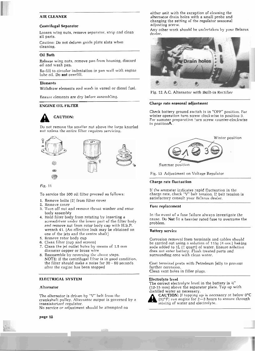
Alternator
The al ternator is dr iven by "V" belt from the crankshaft pulley. Alternator output is governed by a transistorized regulator. No service o r adjustment should be at tempted on
either unit wi th the exception of cleaning the al ternator drain holes wi th a small probe a n d changing the setting of the regulator seasonal adjust ing screw. A n y other work should be undertaken by your Belarus dealer.
Fig. 1 2 A.C. Alternator wi th Built-in Rectifier
Charge rate seasonal adjustment
Check bat tery ground switch is in "OFF" position. For winter operation tu rn sc rew clockwise to position 3. For summer preparat ion tu rn sc rew counter-clockwise to posi t ionA.
Winter position
Summer position
Fig. 1 3 Adjustment on Voltage Regulator
Charge rate fluctuation
If the ammeter indicates rapid fluctuation in the charge rate , check "V" belt tension. If belt tension is sat isfactory consult your Belarus dealer.
Fuse replacement
In the event of a fuse failure a lways investigate the cause. Do Not fit a heavier rated fuse to overcome the problem.
Battery service
Corrosion removal from terminals a n d cables shoulcl be carried out using a solution of 11.5g (4 ozs.) baking soda added to 1L (1 q u a r t ) of water . Ensure solution does not enter bat tery. Flush treated par t s a n d surrounding area wi th clean water .
Coat terminal posts wi th Petroleum Jelly to prevent fur ther corrosion. Clean vent holes in filler plugs.
Electrolyte level The correct electrolyte level in the ba t te ry i s '12"
(12-15 m m ) above the separa tor plate. T o p up wi th distilled w a t e r a s necessary.
Al CAUTION: If topping LIP is necessary at below O°C (32OF) run engine for 2-3 hours to ensure through mixing of wate r a n d electrolyte.
page 12

FUEL SYSTEM Fuel pump lube oil level I
Fuel Filters Thoroughly clean pump body around filling and level ulu.es.
T h e engine is fitted wi th a double filtration sys tem.
Primary Filter (Fig. 21)
T h e primary filter contains no element and serves to separa te wate r and other foreign matter from the diesel fuel. Periodic removal and thorough cleaning is recommended. Drain sediment af ter every 60 hours of engine operation.
Secondary Filter assembly (Fig. 38)
Remove plug "A" every 240 hours to drain off sediment . Change fuel filters af ter 480 operating hours b y removing bolts "B".
Bleeding fuel system
When filter service is complete o r the engine has run out of fuel bleed all a i r from system by opening bleed plug A a n d actuat ing hand p u m p B until a i r free fuel f lows from bleed plug.
Close bleed plug and secure hand pump.
Fig. 1 4 Primer P u m p
Fuel pump lubrication
Operator maintenance of the fuel pump is restricted to lubrication.
Unauthorized adjustment or alteration of the fuel pump in a n y w a y , will cancel war ran ty .
Fig. 15 Fuel P u m p
Remove level plug C If required a d d e ig ine lube oil through filler plug D until oil f lows from level plug hole C.
Re-fit plugs wi th serviceable seal rings.
Fuel pump lube oil change Thoroughly clean p u m p body a round filling, level a n d dra in plugs. Remove dra in plug E, a n d dra in oil. Re-fit drain plug wi th serviceable seal. Remove level a n d filler plugs C & D, fill with engine lube oil to top of level plug C. Allow 60 seconds for oil level to equalize between pump body and governor casing. Add or drain oil a s necessary to obtain correct level. Replace plugs.
Overfilling with lube oil will i~dverse ly affect A operation of the governor mechanism.
page 13
1

SAFETY FIRST According to accident s tat is t ics compiled annually, farming i s dangerous business. Many farmers die each year in preventable t ractor accidents and many more are hurt. Most accidents can be eliminated by simple observance of the following safety rules - be sure you and your operators are familiar wi th them. Use your new Belarus safely.
When a n implement i s to be left on the t ractor which is not in use, never leave it in a raised position. Always lower it.
Place the shift lever in neutral a n d set the parking brake when the t ractor is stopped.
Never oil, grease or adjust the t ractor while it i s moving.
Do not leave the engine running while adjustments or repairs a re made to the tractor o r d r awn equipment.
Hydraulic oil under pressure can cause injury by penetrating the skin or blinding. Always be sure all connections a re tight and there is no damage to the hoses. Relieve all hydraulic pressure before disconnecting hoses.
Do not smoke when filling batteries. Avoid open flame.
Like gasoline, vaporized diesel fuel is dangerous and volatile. Use caution handling any fuel. Do not smoke while filling the tank or servicing the fuel sys tem and avoid refuelling the t ractor when the engine is running.
Use extreme caution when towing loads at road speed. Avoid hard application of the brakes.
Drive s lowly over rough ground.
Adjust headlights so they will not hinder, the vision of oncoming drivers.
Always display a s low moving vehicle sign when driving the t ractor on a road or highway.
Keep the speed down on hillsides and curves to avoid danger of tipping.
Keep sleeves, jackets and other clothing tight and belted. Take extra care with clothing when near moving parts .
Keep a well maintained fire extinguisher in the cab a t all t imes and know how to use it properly.
Never s ta r t or run the t ractor in a closed shed or garage.
Do not s tar t o r r un the t ractor except from the drivers seat.
Never al low any person to ride on the h i tch , , d r awba r or any part of the t ractor except the cab. An operator and one r ider may occupy the cab safely.
During tight tu rns with implements, lift them from the ground to prevent damage to sidewalls. Normal operating tu rns pose no problem.
Avoid jerky s t a r t s when driving out of ditches, gullies o r on steep hills. Engage the clutch slowly.
Do not operate near the edge of a ditch or gully and watch for irregularities such a s holes or large s tones when operating on hillsides.
Never allow the tractor to coast when descendng steep hills o r grades. Always use a gear low enough to maintain complete control.
Always use the d r awba r when hitching heavy loads to be towed.
When hitching equipment to the d r awba r a lways be sure that in making the connection the tractor is moving a w a y from the equipment. Always check past the clevis then move forward.
Common sense is the best safety guideline. Always think every action through, especially if it i s a new or unfamiliar procedure.
page 14
-

FUELS AND LUBRICANTS Diesel Fuel NOTE:
Fuel qual i ty affects the performance a n d service life of a diesel engine. Use of cheap, low qual i ty fuel oil m a y prove costly due to reduced engine life, increased overhaul a n d service costs.
Fuel Specifications
Grade No 1 - D or g rade No 2 - D diesel fuel in accordance wi th ASTM D975 should be used, final selection being dictated b y temperature. Generally, g rade No 1 - D should be used from late fall to spring. Grade No 2 - D from spring to la te fall. If a choice of fuels is available, select the product wi th the lowest su lphur , wate r and sediment content. At al t i tudes in excess of 5,000' use g rade No 1 - D irrespective of temperature.
Refueling the tractor
If your fuel s torage tank outlet is not fitted with a filter use a 1000 mesh filter screen when refueling. On completion of the day's operation fill t ank to minimize condensation.
Fuel Storage
Proper fuel s torage is vitally important to the operation of your tractor. Because of climatic variat ions w e s trongly recommend that your local oil company representat ive i s consulted when planning your s torage facility.
Lubricants
T o minimize total operat ing costs use high qual i ty lubricants of specified grade i s essential. Use of inferior, low cost grease and oils will result in increased w e a r and overhaul costs.
Engine Lubricating and Hydraulic System Oils
Use of a n oil that conforms to one of the following specifications:
Use of series 3 oil is necessary only when su lphur content of diesel fuel exceeds 0.6%
When selecting viscosity consider the: average temperature at your average dai ly s ta r t time expected in the period covered by your next service cycle.
Select oil from the following table:
Temperature O C Single Grade Oil Above 0 S A E 30 O to - 20 S A E 20 Below - 20 S A E 10
When using S A E 5 or S A E 5W - 20 oil increased consumption m a y occur. Check your d ip stick a t more frequent intervals.
Single Grade API Service CD/SD
page 15

LUBRICATION A N D PERIODIC SERVICE The lubrication and preventive service cycle is divided into daily, periodic and seasonal operations. The periodic service frequency is based on a 60 hour cycle. Engine operating hours a re recorded on the tachometer. On completion of the initial 60 hours of operation, servicing will be carried out by your Belarus dealer, free of charge except for oils used. The lubrication and service intervals a r e based on operations under average conditions. If severe conditions a re encountered the t ractor will require service at more frequent intervals.
DAILY OR EVERY 10 HOURS
Component Figure Service Capacity or Measurement Type of Lubricant
Engine crankcase 19 check oil level to upper mark Engine oil
Radiator 20 check coolant level to top tank filler throat. water & antifreeze soluti.,
Fan belt
Tires
General
2 1 check tension 112" deflection 25 lbs force
2 2 check condition & inflation see chart for pressure recommendations
check for loose bolt & nuts , oil and fuel leaks.
60 HOUR SERVICE
Repeat daily service and include
Component Figure Service Capacity or Measurement Type of Lubicant
Primary fuel filter 23 drain sediment motor oil
Hydraulic system 24 & 25 check oil level to upper mark see chart for recommendations
Fuel injection pump 2 6 check oil level to check plug multi-purpose grease
Water pump bearing 2 7 lubricate 3 shots of grease
Clutch release bearing 28 lubricate 8 shots of grease motor oil
Front wheel drive shaft 29, 30, 31 lubricate (520)
Front dr ive axle top bevel (90') 520 only 32 check oil level
Air cleaner
Oil filter
Batteries
until grease becomes visible
to top of filler plug
33 drain & w a s h fill to mark
page 16
3 4 remove and wash
35 check electrolyte level to ring clean water

, DAILY SERVICE
Fig. 19 Check oil level
Fie. 2 1 Check fan belt tension
Fig. 22 Check tire inflation & condition
Fig. 20 Check coolant level
' .
page 17
A- - ... . . .. . . - . - - . - - - . - . . .. . .

60 HOUR SERVICE
Fig. 23 Primary fuel filter, drain sediment .
Fig. 25 Steer ing hydrau l ic system - check oil level
Hydraulic Tank Dip Stick Marking
- Level when auxiliary cylinders are used
n - Normal level without auxiliary cylinders.
page 18

60 HOUR SERVICE
Fig. 26 Injection p u m p oil level check
Fig. 29 Fronl wheel tirive shaft front fitting (520)
Fig. 27 Water pump bearing fitting
page 19

Fig. 30 Front wheel dr ive shaf t centre fitting (520)
Fig. 31 Frvnt \\.heel dr ive shclft rear fitt ing (520)
Fig. 32 Front drive ax][: lop 11~vel [90°) "A" - ant1 lower dr ive case plugs "B" left a n d right hand size
page 20
60 HOUR SERVICE CO.,.~
Fig. 33 Air cleaner
Fig. 34 Oil filter
Fig. 35 (;hec:k battery

240 HOUR SERVICE
Repeat daily and 60 hour service and include
Component Figure Service Capacity or measurement Type of Lubricant
Engine-crankcase 3 6 change oil 15 liters
Fuel injection p u m p 3 7 change oil 0.2 liter
motor oil
motor oil
Secondary fuel filter 3 8 d ra in off sediment
Transmission 3 9 check oil level to check plug S.A.E. 80 EP
Front d r ive axle (520) 40 check oil levels to filler plug see chart
Drive shaft suppor t bearing 4 1 check oil levels to filler plug see chart
Tractor grease fitt ings 42 - 46 lubricate 3-4 sho ts of grease multi-purpose grease
Hydraul ic filter 47,48 w a s h Dealer Service Item
Clutch & Brake adjust Dealer Service Item
~p -
480 HOUR SERVICE
Repeat daily, 60 hour, 240 hour service and include
Component Figure Service Capacity or measurement Type of Lubricant
Air cleaner w a s h in take pipe considered dealer service item a n d element 0.2 liter motor oil
Secondary fuel filter change elements considered dealer service item
page 21

240 HOUR SERVICE // /A
Fig. 36 Oil pan drain plug.
Fig. 38 Secondary fuel filter
0" Fig. 39 Transmission lube check plug. .- -A, "A -ma&, > &
Fig. 37 Fuel injection pump drain plug.
page 22

Fig. 40 Front dr ive axle differential housing check plug. (5201
Fig. 41 Drive shaf t suppor t bearing A - level plug; B - dra in plug.
Fig. 42 Front spindle grease fitt ings (500) left & right hand side.
Fig. 43 Clutch pedal suppor t grease fitt ing.
page 23
. -

Fig. 44 Three point hitch cross shaft fitt ings.
Fig. 45 Steering shaft un ivers i~ l joint
Fig. 46 Lower draf t l ink adjustment rcducer grease fitt ing.
Fig. 47 Hydraul ic oil fil ter removal
Fig. 48 Hydraul ic oil filter disassembled
_
1 page 24

1 960 HOUR SERVICE I
I Repeat daily, 60 hour, 240 hour and 480 hour service and include
Component Service Capacity or Measurement Type of Lubricant
Front wheel bearings check end plug repack with multi-purpose grease
Cylinder head retorque
Intake and Exhaust valves adjust
Fuel injectors test and adjust
Steering valve adjust worm nut
Intermediate Bearing and check & adjust safety clutch (520)
Transmission change oil 40 liters see chart
Hydraulic tank change oil 20.5 liters see chart
Power steering tank change oil
Accumulator drain
6 liters see chart
This service requires the use of special test equipment. For this reason, the tractor should be serviced by your local Belarus Dealer who is trained and equipped to carry out the service.
SEASON PREVENTIVE MAINTENANCE
I Cold Season Warm Season
When ambient temperature does not rise above 5OC When ambient temperature rises to 5OC and above, service a s follows: service a s follows:
1. Replace summer grade lubricant with winter grade 1. Replace winter grade lubricants with summer grade in engine and hydraulic systems. in the engine and hydraulic systems. 2. Check all electrical equipment for correct operation. 2. Turn seasonal switch on voltage regulator to summer 3. Turn seasonal switch on regulator to winter position. position. 4. Check tire pressure. 3. Check tire pressure. 5. Test anti-freeze solution for proper protection.
LUBRICANT CHART
Component Engine
Fuel injection pump
Hydraulic reservoirs
Air cleaner
Transmission
Front drive axle (520)
Drive shaft support bearing (520)
Hydraulic power steering
Cardan shaft bearing
Summer
SAE 30 shell Rotella H.D. 30 Motor oil SAE 40 shell Tolpa
APT Service CDISD
S.A.E. 90 EP
gear oil
engine oil
SAE 90 EP
Winter
SAE 20 shell Rotella H.D. 20 Motor oil SAE 30 shell Rotella
API Service CDISD
S.A.E. 90 EP
gear oil
engine oil
SAE 90 EP
page 25