Instrumentation and Monitoring of Precast Prestressed ... · of Precast Prestressed Concrete...
12
1 Instrumentation and Monitoring of Precast Prestressed Concrete Pavement Vellore S. Gopalaratnam University of Missouri-Columbia Transportation Seminar January 25, 2008 1/30/2008 UMC MoDOT Page 2 Acknowledgements • Federal Highway Administration – Funding for experimental construction – Suneel Vankar, and Sam Tyson • Missouri Department of Transportation – financial support of project – John Donahue • Missouri Department of Transportation – District Office – Eric Krapf and Barry Horst • Transtec Group, Inc – Dave Merritt • Graduate Students – Cody Dailey, Brent Davis, Grant Luckenbill, Patrick Earney
Transcript of Instrumentation and Monitoring of Precast Prestressed ... · of Precast Prestressed Concrete...
1
Instrumentation and Monitoring of Precast Prestressed Concrete Pavement
Vellore S. GopalaratnamUniversity of Missouri-Columbia
Transportation SeminarJanuary 25, 2008
1/30/2008UMC MoDOTPage 2
Acknowledgements• Federal Highway Administration – Funding for
experimental construction – Suneel Vankar, and Sam Tyson
• Missouri Department of Transportation –financial support of project – John Donahue
• Missouri Department of Transportation –District Office – Eric Krapf and Barry Horst
• Transtec Group, Inc – Dave Merritt• Graduate Students – Cody Dailey, Brent
Davis, Grant Luckenbill, Patrick Earney
2
1/30/2008UMC MoDOTPage 3
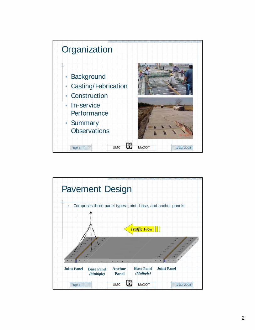
Organization
• Background• Casting/Fabrication• Construction• In-service
Performance• Summary
Observations
1/30/2008UMC MoDOTPage 4
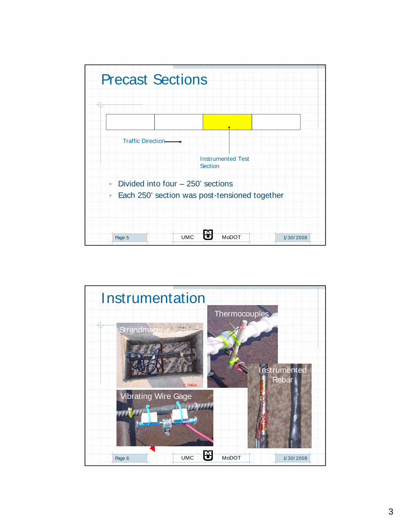
Pavement Design
• Comprises three panel types: joint, base, and anchor panels
Joint Panel Base Panel(Multiple)
Anchor Panel
Base Panel(Multiple)
Joint Panel
Traffic Flow
3
1/30/2008UMC MoDOTPage 5
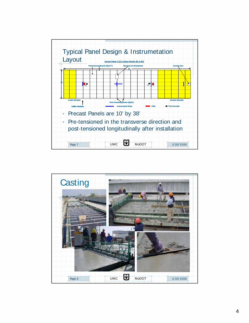
Precast Sections
Traffic Direction
Instrumented Test Section
• Divided into four – 250’ sections• Each 250’ section was post-tensioned together
1/30/2008UMC MoDOTPage 6
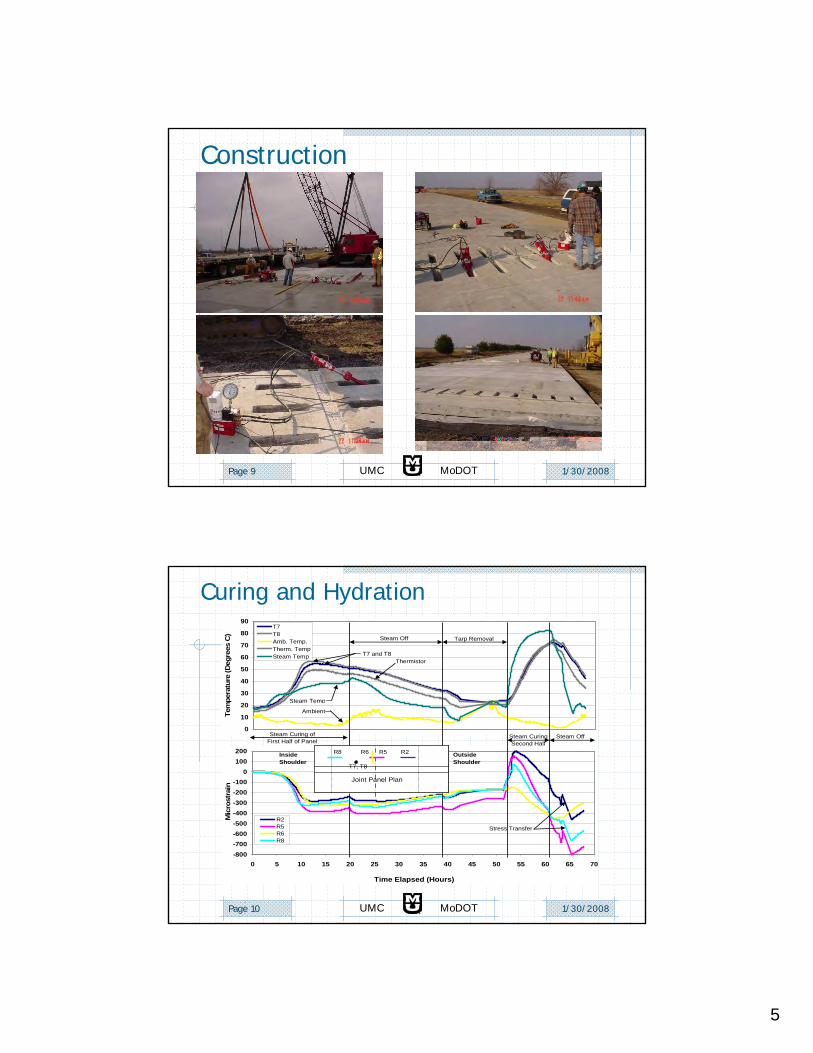
Strandmeter
Instrumentation
Instrumented Rebar
Vibrating Wire Gage
Thermocouples
4
1/30/2008UMC MoDOTPage 7
Typical Panel Design & Instrumetation Layout
• Precast Panels are 10’ by 38’• Pre-tensioned in the transverse direction and
post-tensioned longitudinally after installation
Anchor Panel 1 (C1) & Base Panels (B1 & B2)
VWG ThermocoupleInstrumented Rebar
Inside Shoulder Outside Shoulder
Pretensioned Strands (8@1’3”)
38’
10’
Junction Box
Post-Tensioning Ducts (18@2’)
Blockout for Strandmeter
Traffic Direction
X3 X3
Anchor Panel 1 (C1) & Base Panels (B1 & B2)
VWG ThermocoupleInstrumented Rebar
Inside Shoulder Outside Shoulder
Pretensioned Strands (8@1’3”)
38’
10’
Junction Box
Post-Tensioning Ducts (18@2’)
Blockout for Strandmeter
Traffic DirectionTraffic Direction
X3 X3
1/30/2008UMC MoDOTPage 8
Casting
5
1/30/2008UMC MoDOTPage 9
Construction
1/30/2008UMC MoDOTPage 10
-800-700-600-500-400-300-200-100
0100200
0 5 10 15 20 25 30 35 40 45 50 55 60 65 70
Time Elapsed (Hours)
Mic
rost
rain
R2R5R6R8
R2R5R8 R6
Joint Panel Plan
T7, T8
0
10
20
30
40
50
60
70
80
90
Tem
pera
ture
(Deg
rees
C)
T7T8Amb. Temp.Therm. TempSteam Temp
Stress Transfer
Steam Curing of First Half of Panel
Steam Off Tarp Removal
Steam Curing Second Half
Steam Off
Ambient
Steam Temp
OutsideShoulder
Inside Shoulder
T7 and T8Thermistor
Curing and Hydration
6
1/30/2008UMC MoDOTPage 11
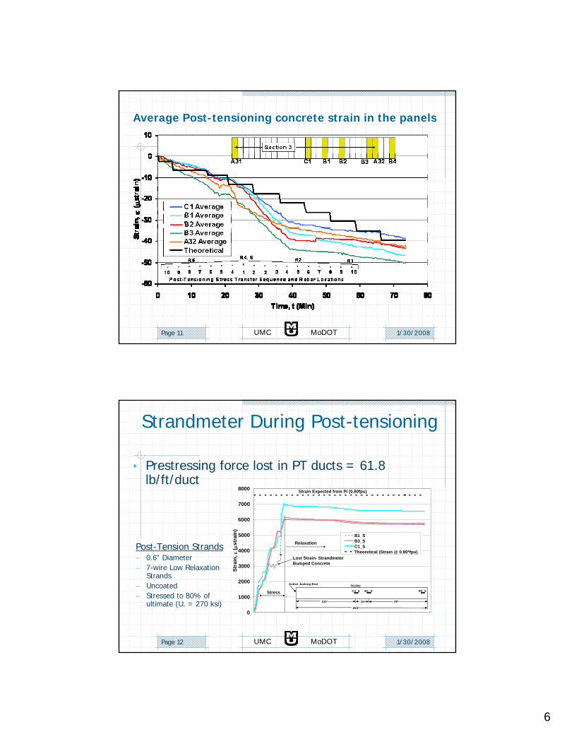
Average Post-tensioning concrete strain in the panels
1/30/2008UMC MoDOTPage 12
Strandmeter During Post-tensioning
0
1000
2000
3000
4000
5000
6000
7000
8000
Stra
in, ε
( μst
rain
)
B1_SB3_SC1_STheoretical (Strain @ 0.80*fpu)
Strain Expected from Pi (0.80fpu)
Relaxation
Stress
Lost Strain- Strandmeter Bumped Concrete
250’
Active Jacking End
C1_S B1_S
125’ 30’ 80’
B3_S
Section
• Prestressing force lost in PT ducts = 61.8 lb/ft/duct
Post-Tension Strands– 0.6” Diameter– 7-wire Low Relaxation
Strands– Uncoated– Stressed to 80% of
ultimate (U. = 270 ksi)
7
1/30/2008UMC MoDOTPage 13
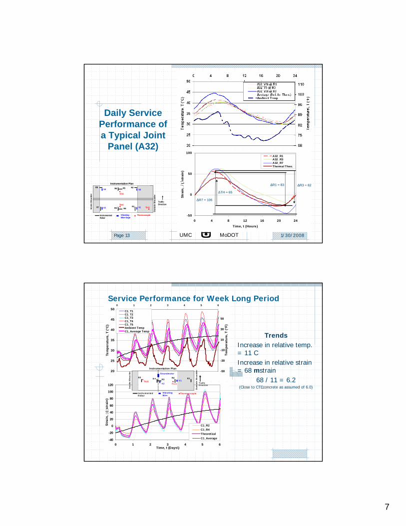
Daily Service Performance of a Typical Joint
Panel (A32)
Instrumentation Plan
Vibrating Wire Gage
Thermocouple Instrumented Rebar
Insi
de S
houl
der
Out
side
Sho
ulde
r T7-8
T1-3 T4-6
Traffic Direction
V4 R8 R6 R5 R2
V2
R1 V1 R4 R3 V3 R7
-50
0
50
100
0 4 8 12 16 20 24Time, t (Hours)
Stra
in, ⎠
( ⎠st
rain
)
A32_R1A32_R3A32_R7Thermal Theo.
ΔR7 = 106
ΔR1 = 83 ΔR3 = 82
ΔTH = 65
Service Performance for Week Long Period
TrendsIncrease in relative temp. = 11 CIncrease in relative strain = 68 mstrain
68 / 11 = 6.2 (Close to CTEconcrete as assumed of 6.0)
20
25
30
35
40
45
500 1 2 3 4 5 6
Tem
pera
ture
, T (°
C)
-50
-30
-10
10
30
50
Tem
pera
ture
, T (°
F)
C1_T1C1_T2C1_T3C1_T4C1_T5Ambient TempC1_Average Temp
-40
-20
0
20
40
60
80
100
120
0 1 2 3 4 5 6Time, t (Days\)
Str
ain,
(
stra
in)
C1_R2C1_R4TheoreticalC1_Average
VibratingWire
Instrumentation Plan
Traffic D irection
Thermocoup leInstru men ted R ebar
Insi
de S
hou
lde
Out
side
Sh
ould
er
T4-5 T 1-3
R2 R1
Strandmeter
R 4 R3
V2
R5 V1
8
1/30/2008UMC MoDOTPage 15
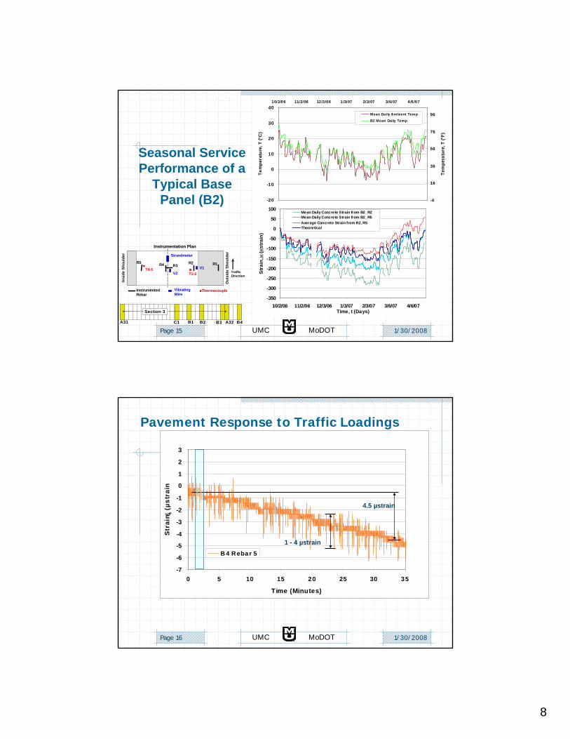
Seasonal Service Performance of a
Typical Base Panel (B2)
A32B3
Section 3
B4B2 B1 C1 A31
Vibrating Wire
Instrumentation Plan
TrafficDirection
Thermocouple Instrumented Rebar
Insi
de S
houl
der
Out
side
Sho
ulde
r
T4-5 T1-3
R2 R1
Strandmeter
R4 R3
V2
R5 V1
-20
-10
0
10
20
30
4010/2/06 11/2/06 12/3/06 1/3/07 2/3/07 3/6/07 4/6/07
Tem
pera
ture
, T (°
C)
-4
16
36
56
76
96
Tem
pera
ture
, T (°
F)
Mean Da ily Ambient Temp
B2 Mean Daily Temp
-350
-300
-250
-200
-150
-100
-50
0
50
100
10/2/06 11/2/06 12/3/06 1/3/07 2/3/07 3/6/07 4/6/07Time, t (Days)
Str
ain,
ℵ ( ℵ
stra
in)
Mean Daily Concrete Strain from B2_R2Mean Daily Concrete Strain from B2_R5Average Concrete Strain from R2, R5Theoretical
1/30/2008UMC MoDOTPage 16
Pavement Response to Traffic Loadings
-7
-6
-5
-4
-3
-2
-1
0
1
2
3
0 5 10 15 2 0 25 30 35
Time (Minutes)
Str
ain, ξ
(µs
trai
n
B 4 R ebar 5
4.5 µstrain
1 - 4 µstrain
9
1/30/2008UMC MoDOTPage 17
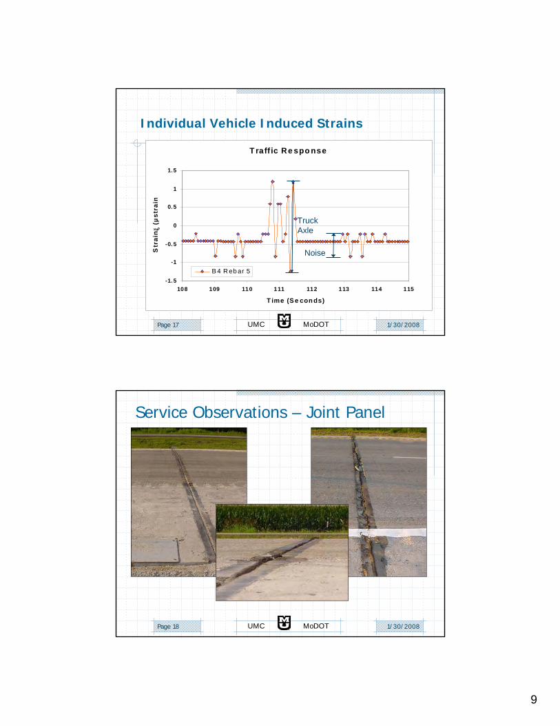
Individual Vehicle Induced Strains
VibratingWire
Instrumentation Plan
Traffic Direction
Thermocouple Instrumented Rebar
Insi
de S
houl
der
Out
side
Sho
ulde
r
T4-6T1-3
R2 R1 R4 R3
V2
R5V1
T7
T raff ic Re spo nse
-1.5
-1
-0.5
0
0.5
1
1.5
108 109 110 111 112 113 114 115
T ime (S e con ds)
Str
ain
, ξ (µ
stra
in
B 4 R eb ar 5
Noise
Truck Axle
1/30/2008UMC MoDOTPage 18
Service Observations – Joint Panel
10
1/30/2008UMC MoDOTPage 19
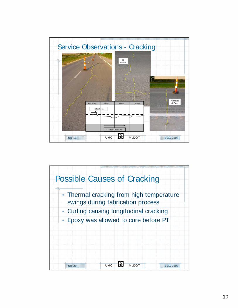
Service Observations - Cracking
Traffic Direction
B2 Base Base Base Base
Blockout
12 Inches
At Middle of Panel
1/30/2008UMC MoDOTPage 20
Possible Causes of Cracking
• Thermal cracking from high temperature swings during fabrication process
• Curling causing longitudinal cracking• Epoxy was allowed to cure before PT

11
1/30/2008UMC MoDOTPage 21
Weather Related Issues• Summer heat waves were problematic for
sensitive circuitry.
– Addition of a shade roof – Larger heat sinks, with
strategically placed fans– Military grade parts since
exceeding Max. Junction Temp.
1/30/2008UMC MoDOTPage 22
Weather Related Issues• Water and Lightning won’t stay away
– Condensation and leakage due to worn seals
– Corrosion– Addition of circuit protection diodes
– in line and on regulators– Path to ground
12
1/30/2008UMC MoDOTPage 23
Summary Observations• Overall the project provided useful insights on the
performance of precast pavement system• Need to avoid thermal shock during early age• Fabrication/alignment issues to be addressed• Joint performance can be improved• As-built post-tensioning stress location dependent• Friction plays a role – incorporate in design• Thermal strains single-most significant loading• Cracking could be minimized through more careful
fabrication/construction
1/30/2008UMC MoDOTPage 24
Questions?