INSTRUMENTAL DCF (FEMORAL) - Interempresas · Tras el abordaje, la instrumentación permite seguir...
48
INSTRUMENTAL DCF (FEMORAL)
Transcript of INSTRUMENTAL DCF (FEMORAL) - Interempresas · Tras el abordaje, la instrumentación permite seguir...
INSTRUMENTAL DCF (FEMORAL)

3
ABORDAJE QUIRÚRGICO / SURGICAL APPROACH 4
SECUENCIA QUIRÚRGICA / SURGICAL SEQUENCE 4
TÉCNICA QUIRÚRGICA / SURGICAL TECHNIQUE 5
1. TIEMPO FEMORAL / FEMORAL TIME 5
1.1 Perforación inicial / Initial perforation 5
1.2 Introducción de la varilla de alineación endomedular / Insertion of the intramedullary alignment rod 5
1.3 Ajuste, posicionamiento y fijación de la guía de corte distal / Adjustment, positioning and fixation of the distal cutting guide 6
1.3.1 Ajuste de la guía de corte distal / Adjustment of the distal cutting guide 6
1.3.2 Alineación del varo-valgo / Varus-valgus alignment 7
1.3.3 Posicionamiento de la guía de corte distal / Positioning of the distal cutting guide 7
1.3.4 Fijación de la guía de corte distal / Fixation of the distal cutting guide 8
1.4 Corte distal / Distal cutting 8
1.5 Medición del tamaño femoral y giro externo / Measurement of femoral size and outward rotation 9
1.6 Instalación del bloque de corte “4 en 1” / Installation of the 4-in-1 cutting block 11
1.7 Resección femoral anterior, posterior y biseles / Anterior and posterior femoral resection and bevels 11
1.8 Extracción del bloque de corte / Removal of the cutting block 12
1.9 Implantación del componente femoral de prueba / Implantation of the trial femoral component 12
2. TIEMPO TIBIAL / TIBIAL TIME 14
2.1 Nivel de resección / Level of resection 15
2.2 Corte tibial / Tibial cutting 17
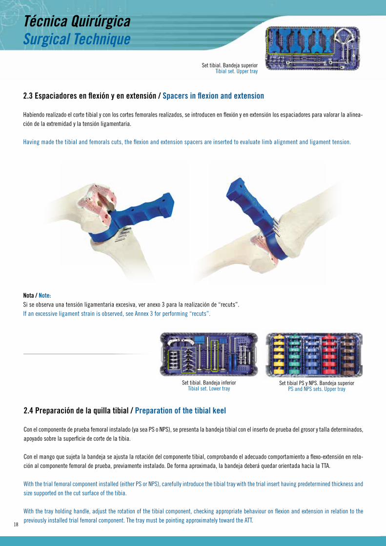
2.3 Espaciadores en flexión y en extensión / Spacers in flexion and extension 18
2.4 Preparación de la quilla tibial / Preparation of the tibial keel 18
2.5 Comprobación con los componentes de prueba / Checking with trial components 20
3. TIEMPO PATELAR / PATELLAR TIME 22
3.1 Medición del espesor / Thickness measurement 22
3.2 Corte y perforación rotuliano / Patellar cutting and perforation 22
4. IMPLANTACIÓN DEFINITIVA / FINAL IMPLANTATION 24
ANEXOS / ANNEXES 25
IMPLANTES E INSTRUMENTAL / IMPLANTS AND INSTRUMENTS 36
NOTAS / NOTES 45
Índice / Index

4
ABORDAJE QUIRÚRGICO / SURGICAL APPROACH Se emplea una incisión central anterior con artrotomía pararrotuliana interna y luxación externa de la rótula que, en sentido proximal, se extiende hasta el tendón del cuádriceps y, distalmente, hasta la tuberosidad tibial.
An anterior midline incision with internal parapatellar arthrotomy and external patellar dislocation is made which extends proximally to the quadriceps tendon, and distally to the tibial tuberosity.
SECUENCIA QUIRÚRGICA / SURGICAL SEQUENCE
After the surgical approach, the instrumentation allows following different surgical sequences. We can start either by first making the tibial cutting for freeing joint space and then working more comfortably in the femoral time, or by first making the cuts of the femur, the sequence of which is shown below:
1. Distal femoral cutting2. Anterior and posterior femoral cuttings and bevels3. PS/NPS choice4. Cutting of the intercondylar box (in case of PS)5. Placement of the trial femoral prosthesis6. Tibial cutting7. Checking spaces in flexion and extension8. Preparation of the tibial keel9. Acting on the patella10. Checking mobility and stability with trial implants11. Placement of the final prosthesis
Suture by planes, leaving Redon suction drains optionally at the discretion of the surgeon.
Tras el abordaje, la instrumentación permite seguir distintas secuencias quirúrgicas. Podemos comenzar bien realizando primero el corte tibial para liberar espacio articular y trabajar posteriormente con mayor comodidad en el tiempo femoral, o bien realizando primero los cortes del fémur cuya secuencia detallamos a continuación:
1. Corte distal femoral2. Cortes anterior, posterior y biseles femorales3. Elección PS/NPS4. Corte del cajetín intercondilar (en caso de PS)5. Colocación de la prótesis de prueba femoral6. Corte tibial7. Comprobación de los espacios en flexión y en extensión8. Preparación de la quilla tibial9. Actuación sobre la rótula10. Comprobación de la movilidad y estabilidad con los implantes de prueba11. Colocación de la prótesis definitiva
Cierre por planos dejando redones aspirativos, de manera opcional, según criterio del cirujano.
5
Set femoral 1. Bandeja superiorFemoral set 1.Upper tray
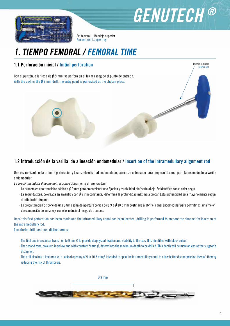
Once this first perforation has been made and the intramedullary canal has been located, drilling is performed to prepare the channel for insertion of the intramedullary rod.The starter drill has three distinct areas:
· The first one is a conical transition to 9 mm Ø to provide diaphyseal fixation and stability to the axis. It is identified with black colour.· The second zone, coloured in yellow and with constant 9 mm Ø, determines the maximum depth to be drilled. This depth will be more or less at the surgeon’s discretion.· The drill also has a last area with conical opening of 9 to 10.5 mm Ø intended to open the intramedullary canal to allow better decompression thereof, thereby reducing the risk of thrombosis.
1. TIEMPO FEMORAL / FEMORAL TIME1.1 Perforación inicial / Initial perforation
Con el punzón, o la fresa de Ø 9 mm, se perfora en el lugar escogido el punto de entrada.With the awl, or the Ø 9 mm drill, the entry point is perforated at the chosen place.
1.2 Introducción de la varilla de alineación endomedular / Insertion of the intramedullary alignment rod
Una vez realizada esta primera perforación y localizado el canal endomedular, se realiza el brocado para preparar el canal para la inserción de la varilla endomedular.La broca iniciadora dispone de tres zonas claramente diferenciadas:
· La primera es una transición cónica a Ø 9 mm para proporcionar una fijación y estabilidad diafisaria al eje. Se identifica con el color negro.· La segunda zona, coloreada en amarillo y con Ø 9 mm constante, determina la profundidad máxima a brocar. Esta profundidad será mayor o menor según el criterio del cirujano.· La broca también dispone de una última zona de apertura cónica de Ø 9 a Ø 10.5 mm destinada a abrir el canal endomedular para permitir así una mejor descompresión del mismo y, con ello, reducir el riesgo de trombos.
Ø 9 mm
Punzón IniciadorStarter awl

6
Set femoral 1. Bandeja superiorFemoral set 1.Upper tray
1.3 Ajuste, posicionamiento y fijación de la guía de corte distal / Adjustment, positioning and fixation of the distal cutting guide
Se ajusta el posicionador de guía de corte a “0” en caso de querer realizar el corte habitual a 8 mm del apoyo distal, ya que el componente femoral a implantar tiene 8 mm de espesor condilar. No obstante, puede ajustarse la telescopía del posicionador a la distancia que se estime oportuna desde “-4” a “+8”.
Se fija la posición distal alcanzada girando la palanca de bloqueo de “open” a “closed” y se monta la guía de corte distal sobre el extremo del posicionador.
The cutting guide positioner is set to “0” in case you want to make the usual cut at 8 mm from the distal support, since the femoral component to be implanted has a condylar thickness of 8 mm. However, the telescoping of the positioner can be adjusted to the distance deemed appropriate from “-4” to “+8”.
The distal position reached is fixed by turning the lock lever from “open” to “closed”, and the distal cutting guide is mounted on the end of the positioner
Broca iniciadoraStarter drill
Varilla de alineaciónAlignment rod
Marca límite máximo de introducciónMaximum insertion limit mark
Con la ayuda del mango en “T” de anclaje rápido, se introduce la varilla de alineación endomedular a través de la perforación anteriormente realizada, hasta alcanzar como máximo la marca grabada en el eje endomedular, dejando así sin introducir una longitud suficiente que permita instalar la guía de alineación del varo-valgo femoral.
Una vez introducida la varilla de alineación se retira el mango en “T”.
With the help of the Quick Coupling “T” handle, the intramedullary alignment rod is inserted through the perforation previously made until reaching, as a maximum, the mark stamped on the intramedullary shaft, thus leaving not inserted a length that is sufficient to allow installation of the femoral varus-valgus alignment guide.
Once the alignment rod has been inserted, the handle “T” is removed.
1.3.1 Ajuste de la guía de corte distal / Adjustment of the distal cutting guide
DesbloqueadoUnlocked
0
BloqueadoLocked
0
Guía de corte distalDistal cutting guide
Posicionador de guía de corteCutting guide positioner

7
Set femoral 1. Bandeja superiorFemoral set 1.Upper tray
Con la guía de alineación en la mano, se gira su cuerpo graduado central para seleccionar el ángulo de alineación requerido.Una vez seleccionado, se introduce el posicionador de la guía de corte distal, con ella montada, a través de su ranura.
With the alignment guide in hand, its central graduated body is rotated to select the required alignment angle.Once the selection has been made, the positioner of the distal cutting guide is inserted, with the latter mounted on it, through the respective slot.
1.3.2 Alineación del varo-valgo / Varus-valgus alignment
Ángulo de alineaciónAngle of alignment
Posicionador de guía de corte + Guía de corte distalCutting guide positioner + Distal cutting guide
Ranura de apoyo distalDistal support slot
El montaje de la guía de corte con su posicionador y éste, a su vez, sobre la guía de alineación varo-valgo, se introduce a través del eje endomedular hasta contactar con la parte distal del fémur, asentándose la guía de corte distal sobre la parte anterior del fémur.
Es recomendable que la rotación de la guía de corte se posicione paralela a la línea transepicondilar.
1.3.3 Posicionamiento de la guía de corte distal / Positioning of the distal cutting guide
The assembly of the cutting guide with its positioner and this, in turn, on the varus-valgus alignment guide, is inserted through the intramedullary shaft to contact the distal femur, and the distal cutting guide is seated on the anterior femur.
It is recommended that the rotation of the cutting guide is positio-ned parallel to the transepicondylar line.
Nota / Note:En caso de necesidad el apoyo distal de la guía de alineación dispone de orificios para la introducción de pins y permite una mayor estabilidad. La inserción del pin deberá realizarse sobre el apoyo distal del cóndilo más prominente.
The distal support has alignment guide holes for the insertion of pins and allows greater stability when needed. The insertion of the pin must be carried out on the distal support of the most prominent condyle.
Guía de alineación varo-valgoAlignment varus-valgus guide
8
Set femoral 1. Bandeja superiorFemoral set 1.Upper tray
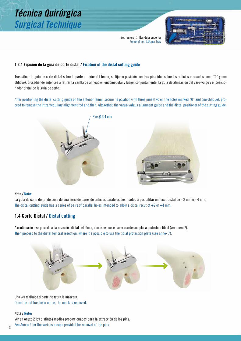
A continuación, se procede a la resección distal del fémur, donde se puede hacer uso de una placa protectora tibial (ver anexo 7).Then proceed to the distal femoral resection, where it´s possible to use the tibial protection plate (see annex 7).
Tras situar la guía de corte distal sobre la parte anterior del fémur, se fija su posición con tres pins (dos sobre los orificios marcados como “0” y uno oblicuo), procediendo entonces a retirar la varilla de alineación endomedular y luego, conjuntamente, la guía de alineación del varo-valgo y el posicio-nador distal de la guía de corte.
After positioning the distal cutting guide on the anterior femur, secure its position with three pins (two on the holes marked “0” and one oblique), pro-ceed to remove the intramedullary alignment rod and then, altogether, the varus-valgus alignment guide and the distal positioner of the cutting guide.
1.3.4 Fijación de la guía de corte distal / Fixation of the distal cutting guide
Pins Ø 3.4 mm
1.4 Corte Distal / Distal cutting
Nota / Note:La guía de corte distal dispone de una serie de pares de orificios paralelos destinados a posibilitar un recut distal de +2 mm o +4 mm.The distal cutting guide has a series of pairs of parallel holes intended to allow a distal recut of +2 or +4 mm.
Una vez realizado el corte, se retira la máscara.Once the cut has been made, the mask is removed.
Nota / Note:Ver en Anexo 2 los distintos medios proporcionados para la extracción de los pins.See Annex 2 for the various means provided for removal of the pins.

9
Set femoral 1. Bandeja inferiorFemoral set 1. Lower tray
Con la rodilla a 90º, se realiza la medición del tamaño femoral asegurando el contacto con el corte distal y los cóndilos posteriores del fémur. Se ajusta la profundidad en horizontal el estilete palpador haciendo coincidir la lectura grabada en éste con la talla mostrada en el eje de medición vertical del medidor.
With the knee at 90 degrees, measure the femoral size while ensuring contact with the distal cut and the posterior condyles of the femur.Horizontally, the probe stylus is adjusted by the depth of the probe stylus is adjusted by matching the reading recorded on this with the size shown on the vertical measurement axis of the gauge.
Estilete palpadorProbe stylus
Lectura de talla femoralReading femoral size
1.5 Medición del tamaño femoral y giro externo / Measurement of femoral size and outward rotation
Medidor femoralFemoral gauge
Mango extraíbleRemovable handle
Una vez seleccionada la talla femoral, se realiza el giro a externo (de 0º a 9º) y se fija su posición abatiendo ligeramante hacia abajo el mango para luego retirarlo. Por defecto, se recomienda aplicar un giro a externo de 3º.
Once the femoral size is chosen, perform outward rotation (0-9º) and secure its position by slightly turning down the handle, then remove it. By default, it is recommended to apply an outward rotation of 3°.
Nota / Note:El medidor dispone de ranuras laterales que simulan la altura del corte anterior, según la talla, con lo que el cirujano podrá comprobar la altura del corte anterior y, con ello, prevenir el riesgo de “notching”.The gauge has lateral grooves simulating the height of the previous cutting according to the size, so that the surgeon can check the height of the previous cutting, thus preventing the risk of “notching”.
Misma tallaSame size
10
Nota / Note:Ver Anexo 1 para casos con pacientes con cóndilos hipoplásicos.See Annex 1 for cases of patients with hypoplastic condyles.
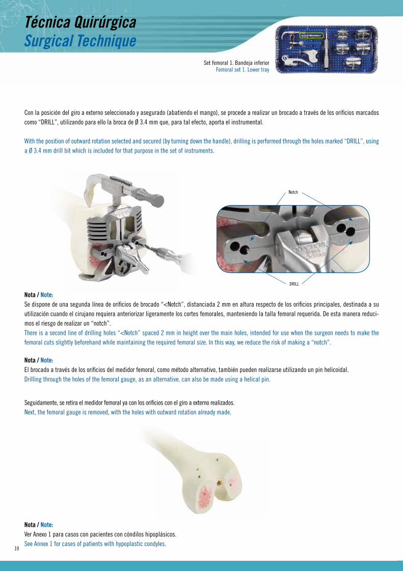
Seguidamente, se retira el medidor femoral ya con los orificios con el giro a externo realizados.Next, the femoral gauge is removed, with the holes with outward rotation already made.
Con la posición del giro a externo seleccionado y asegurado (abatiendo el mango), se procede a realizar un brocado a través de los orificios marcados como “DRILL”, utilizando para ello la broca de Ø 3.4 mm que, para tal efecto, aporta el instrumental.
With the position of outward rotation selected and secured (by turning down the handle), drilling is performed through the holes marked “DRILL”, using a Ø 3.4 mm drill bit which is included for that purpose in the set of instruments.
Nota / Note:Se dispone de una segunda línea de orificios de brocado “<Notch”, distanciada 2 mm en altura respecto de los orificios principales, destinada a su utilización cuando el cirujano requiera anteriorizar ligeramente los cortes femorales, manteniendo la talla femoral requerida. De esta manera reduci-mos el riesgo de realizar un “notch”.There is a second line of drilling holes “<Notch” spaced 2 mm in height over the main holes, intended for use when the surgeon needs to make the femoral cuts slightly beforehand while maintaining the required femoral size. In this way, we reduce the risk of making a “notch”.
Notch
DRILL
Nota / Note:El brocado a través de los orificios del medidor femoral, como método alternativo, también pueden realizarse utilizando un pin helicoidal.Drilling through the holes of the femoral gauge, as an alternative, can also be made using a helical pin.
Set femoral 1. Bandeja inferiorFemoral set 1. Lower tray

11
Set femoral 1. Bandeja inferiorFemoral set 1. Lower tray
Con el bloque de corte correspondiente a la medición realizada, se fija el introductor/extractor sobre su orificio central para impactar los pins traseros del bloque sobre los orificios realizados previamente.
With the cutting block corresponding to the measurement made, fix the impactor/extractor on its central hole to impact the rear pins of the block on the holes previously made.
Introductor/ExtractorImpactor/Extractor
1.6 Instalación del bloque de corte “4 en 1” /Installation of the “4-in-1” cutting block
Tras lograr el contacto distal del bloque, se asegura su posición mediante la introducción de un par de pins laterales.
After achieving the distal contact of the block, secure its position by inserting a couple of side pins.
Pins Ø 3.4 mm
Se realizan los cortes femorales y, en última instancia, los biseles.
Femoral cuts are made and, ultimately, the bevels.
1.7 Resección femoral anterior, posterior y biseles / Anterior and posterior femoral resection and bevels
Bloque de corteCutting block
12
Set femoral 2. Bandeja superiorFemoral set 2. Upper tray
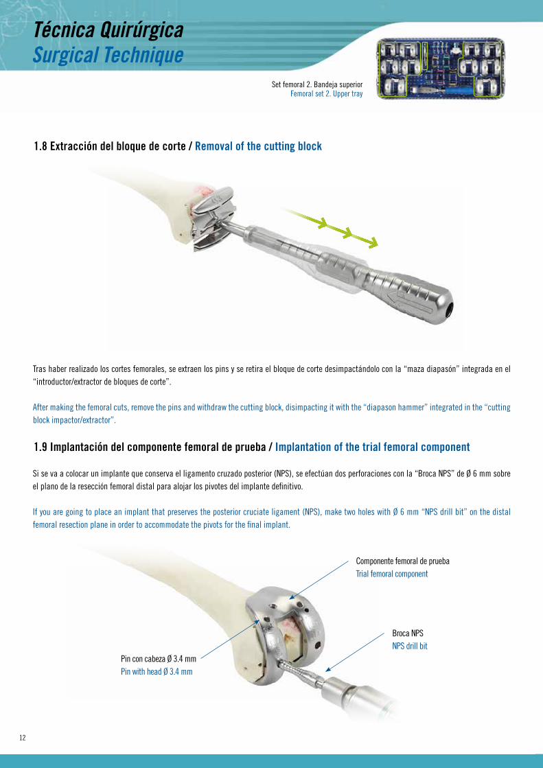
Tras haber realizado los cortes femorales, se extraen los pins y se retira el bloque de corte desimpactándolo con la “maza diapasón” integrada en el “introductor/extractor de bloques de corte”.
After making the femoral cuts, remove the pins and withdraw the cutting block, disimpacting it with the “diapason hammer” integrated in the “cutting block impactor/extractor”.
1.8 Extracción del bloque de corte / Removal of the cutting block
Si se va a colocar un implante que conserva el ligamento cruzado posterior (NPS), se efectúan dos perforaciones con la “Broca NPS” de Ø 6 mm sobre el plano de la resección femoral distal para alojar los pivotes del implante definitivo.
If you are going to place an implant that preserves the posterior cruciate ligament (NPS), make two holes with Ø 6 mm “NPS drill bit” on the distal femoral resection plane in order to accommodate the pivots for the final implant.
1.9 Implantación del componente femoral de prueba / Implantation of the trial femoral component
Componente femoral de pruebaTrial femoral component
Broca NPSNPS drill bit
Pin con cabeza Ø 3.4 mmPin with head Ø 3.4 mm

13
Set femoral 2. Bandeja superiorFemoral set 2. Upper tray
Si se escoge implantar una estabilizada posterior (PS), se acopla al componente NPS la guía de sierra para recortar el intercóndilo. Llegados a este punto, se puede volver a hacer uso de la placa protectora tibial (ver anexo 7).If you choose to implant a posterior stabilized (PS) prosthesis, couple the saw guide to the NPS component to recut the intercondyle. At this point, it´s possible to use again the tibial protection plate (see annex 7).
Guía de corte intercondilarIntercondylar cutting guide
Nota / Note:El componente femoral de prueba dispone de dos orificios practicados sobre el plano del bisel anterior, destinado a la introducción de un pin Ø 3.4 mm corto con cabeza para asegurar su posición durante la resección intercondilar.The trial femoral component has two holes drilled on the plane of the anterior bevel, intended for the insertion of a Ø 3.4 mm short headed pin to secure its position, during intercondylar resection.
Posteriormente al corte, se retira la guía de corte intercondilar y se monta el cajetín intercondilar de prueba PS correspondiente a su talla, convirtién-dose así el componente femoral de prueba “NPS” en “PS”.
After making the cutting, remove the intercondylar cutting guide and mount the PS trial intercondylar box corresponding to its size, whereby the “NPS” trial femoral component is converted to “PS”.
Nota / Note:Para asegurar un correcto montaje del cajetín intercondilar de prueba, es necesario realizar una buena resección intercondilar. Para ello, se recomienda realizar los cortes intercondilares con una sierra de banda estrecha. Se puede utilizar también el Cincel del instrumental, sólo en casos necesarios, para realizar repasos finales puntuales.To ensure proper assembly of the trial intercondylar box, it is necessary to make a good intercondylar resection. For this, it is recommended to use a narrow band saw to make the intercondylar cuts. You can also use the chisel of the set of instruments, only where necessary, for final punctual recutting.
Componente femoral de prueba NPS convertido en PS montado en cajetín intercondilar de prueba PS.Trial NPS femoral component converted to PS

14
2. TIEMPO TIBIAL / TIBIAL TIMEEl instrumental permite realizar la osteotomía con la guía extramedular, endomedular o la asociación de ambas.La plantilla de corte tibial (izquierda o derecha) se instala sobre la varilla extramedular que, a su vez, distalmente aloja una pinza ajustable al tobillo.
Si se va a utilizar la guía extramedular, en la zona proximal se ensambla una varilla corta auxiliar provista de dos espículas que se fijan en la zona de las espinas tibiales una vez se tiene decidida la posición de la varilla extramedular.
Si se va a utilizar la guía endomedular, previamente se efectúa la obertura del canal endomedular tibial mediante el punzón y la broca (el punto de entrada se sitúa entre las espinas tibiales). A través de la obertura practicada introduciremos el eje endomedular ensamblando a su zona proximal la varilla extramedular.
The set of instruments allows performing the osteotomy with an extramedullary or intramedullary guide, or a combination of both.The tibial cutting template (left or right) is mounted on the extramedullary rod which, in turn, distally houses a clamp adjustable to the ankle.
If you choose to use the extramedullary guide, on the proximal area you must assemble a short auxiliary rod provided with two spikes to be fixed on the area of the tibial spines once you have determined the position of the extramedullary rod.
If you are going to use the intramedullary guide, you must previously open the tibial intramedullary canal by using the awl and the drill bit (the entry point is located between the tibial spines). Through the opening made, introduce the intramedullary shaft, assembling to its proximal area the extramedullary rod.
Set tibial. Bandejas superior e inferiorTibial set. Upper and lower trays
Nota / Note:En los casos en los que la tibia sea vara, se aconseja efectuar el punto de entrada un poco más externo y si es valga, un poco más medial. La guía endomedular se ubica en la bandeja superior del set femoral 1.In cases of tibia vara, it is advisable to locate the entry point a little more outwardly; in cases of tibia valga, a little more medial. The intramedullary guide is located on femoral set 1, upper tray.
Espícula anteriorAnterior spike
Espícula posteriorPosterior spike
Guía extramedularExtramedullary guide
Varilla extramedularExtramedullary rod
Plantilla de corte tibialTibial cutting template
Guía endomedularIntramedullary guide
GUÍA EXTRAMEDULAR / EXTRAMEDULLARY GUIDE GUÍA ENDOMEDULAR / INTRAMEDULLARY GUIDE
PalpadorProbe
Varilla extramedularExtramedullary rod

15
2.1 Nivel de resección / Level of resection
Se instala el palpador en el alojamiento de la guía de corte y, con el extremo corto del palpador “10”, se busca el apoyo en el plato menos afectado fijando, provisionalmente, la guía de corte a este nivel. Tras este paso, con el extremo largo “0” del palpador, se localiza la zona tibial más deprimida del plato más afectado, pudiendo entonces presentarse estas dos situaciones:
• Que el extremo “0” no contacte, con lo que se debe descender la guía de corte tibial hasta propiciar el contacto. A esta altura de guía de corte se realiza una resección de 1 mm por debajo de la zona más usurada.
• Que el extremo “0” no quepa. En esta situación se bloquea la guía de corte.
Install the probe in the housing of the cutting guide and, with the short end of the “10” probe, seek support on the least affected plateau of the tibia and provisionally fix the cutting guide at this level. After this step, with the long end “0” of the probe, locate the most depressed tibial area of the most affected plateau; these two situations may then be found:
• The “0” end , does not contact; then you should lower the tibial cutting guide to facilitate the contact. At this level of the cutting guide, make a 1 mm resection below the most worn area.
• The “0” end does not fit. In this situation, lock the cutting guide.
PALPACIÓN “10” / PALPATION “10” PALPACIÓN “0” / PALPATION “0”
Palpador “0-10”“0-10” Probe
Palpación “10”“10” Palpation
Palpación “0”“0” Palpation

16
Se fija la guía de corte a la tibia con cuatro pins sin cabeza que se introducen a través de los orificios más distales (la línea marcada con el “0”). Se completa la fijación con la opción de uno o dos pins con cabeza de forma oblicua y convergente.
The cutting guide is fixed to the tibia with four headless pins to be inserted through the most distal holes (the line marked “0”). Fixation is to be com-pleted with the choice of one or two pins with oblique convergent shape head.
Set tibial. Bandeja inferiorTibial set. Lower tray
Para bloquear la guía de corte tibial sobre la varilla extramedular se aprieta el tornillo de bloqueo utilizando el destornillador hexagonal de 2.5 mm.To lock the tibial cutting guide on the extramedullary rod, tighten the locking screw using the 2.5 mm hexagonal driver.
Set tibial. Bandeja superiorTibial set. Upper tray
Nota / Note:Se recomienda usar previamente una broca de Ø 3.2 mm.The use of an Ø 3.2 mm drill bit is recommended.
Bloqueo de guía de corte tibialLocking tibial cutting guide
Orificio 2º pin oblicuo2nd oblique pin hole
Pin oblicuoOblique pin

17
2.2 Corte tibial / Tibial cutting
Con la guía de corte sólidamente fijada a la tibia, se retira el sistema de guías endomedulares y/o extramedulares utilizado y se realiza la osteotomía de la zona epifisaria de la tibia.
With the cutting guide firmly attached to the tibia, the system of cut intramedullary and/or extramedullary guides used is removed and the osteotomy of the epiphyseal area of the tibia is performed.
Nota / Note:Se aconseja utilizar hojas de sierra de 1.3 mm de grosor. Una sierra de menor grosor puede combarse y producir cortes inadecuados.It is recommended to use saw blades 1.3 mm thick. A thinner saw can warp causing improper cuts.
Una vez efectuado el corte, para extraer la guía, se extrae el pin oblicuo con cabeza. Retirado el fragmento tibial, se recorta con una gubia los osteofitos periféricos, si los hubiera, y se efectúa la medida de la bandeja tibial con las plantillas.
Once the cut is made, to remove the guide, remove the oblique headed pin. Once the tibial fragment is removed, trim the peripheral osteophytes, if any, using a gouge, and make the measurement of the tibial tray with the templates.
Set tibial. Bandeja inferiorTibial set. Lower tray
Plantilla tibialTibial template Mango soporte plantilla
Tibial template handle
Varilla de alineaciónAlignment shaft Nota / Note:
Se recomienda no retirar los cuatro pins sin cabeza hasta haber realizado los cortes distal y posterior del fémur ya que pueden ser de utilidad en caso de ne-cesitar realizar un “recut”.It is recommended not to remove the four headless pins until you have done the distal and posterior femoral cuts, as they may be useful if you need to perform a “recut”.
18
2.3 Espaciadores en flexión y en extensión / Spacers in flexion and extension
Habiendo realizado el corte tibial y con los cortes femorales realizados, se introducen en flexión y en extensión los espaciadores para valorar la alinea-ción de la extremidad y la tensión ligamentaria.
Having made the tibial and femorals cuts, the flexion and extension spacers are inserted to evaluate limb alignment and ligament tension.
Set tibial. Bandeja superiorTibial set. Upper tray
Nota / Note:Si se observa una tensión ligamentaria excesiva, ver anexo 3 para la realización de “recuts”.If an excessive ligament strain is observed, see Annex 3 for performing “recuts”.
Set tibial PS y NPS. Bandeja superiorPS and NPS sets. Upper tray
2.4 Preparación de la quilla tibial / Preparation of the tibial keel
Con el componente de prueba femoral instalado (ya sea PS o NPS), se presenta la bandeja tibial con el inserto de prueba del grosor y talla determinados, apoyado sobre la superficie de corte de la tibia.
Con el mango que sujeta la bandeja se ajusta la rotación del componente tibial, comprobando el adecuado comportamiento a flexo-extensión en rela-ción al componente femoral de prueba, previamente instalado. De forma aproximada, la bandeja deberá quedar orientada hacia la TTA.
With the trial femoral component installed (either PS or NPS), carefully introduce the tibial tray with the trial insert having predetermined thickness and size supported on the cut surface of the tibia.
With the tray holding handle, adjust the rotation of the tibial component, checking appropriate behaviour on flexion and extension in relation to the previously installed trial femoral component. The tray must be pointing approximately toward the ATT.
Set tibial. Bandeja inferiorTibial set. Lower tray

19
Cuando está clara la posición de rotación adecuada, se marca una señal entre la bandeja y el hueso que servirá de referencia para, posteriormente y una vez retirado el polietileno de prueba, fijar la bandeja con dos pins con cabeza.
Se introduce el escoplo-quilla de la talla escogida sobre la bandeja tibial hasta el tope. Se retira el mango de la quilla y se coloca el inserto de prueba para efectuar la comprobación definitiva con los componentes tibial y femoral de prueba correspondientes.
When the appropriate rotation position has been clearly determined, make a mark between the tray and the bone for later reference, and when the trial polyethylene has been removed, fix the tray with two headed pins.
Insert the keel-chisel of the chosen size all the way into the tibial tray. Remove the keel handle, then place the trial insert to perform the final verification with the corresponding tibial and femoral trial components.
20
Set tibial. Bandeja inferiorTibial set. Lower tray
PS
NPS
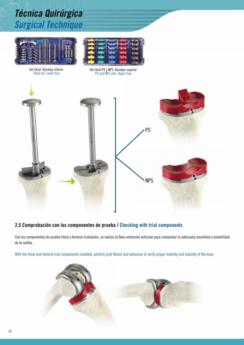
2.5 Comprobación con los componentes de prueba / Checking with trial components
Con los componentes de prueba tibial y femoral instalados, se realiza la flexo-estensión articular para comprobar la adecuada movilidad y estabilidad de la rodilla.
With the tibial and femoral trial components installed, perform joint flexion and extension to verify proper mobility and stability of the knee.
Set tibial PS y NPS. Bandeja superiorPS and NPS sets. Upper tray

21
Tras efectuar dicha comprobación, se retira el inserto de prueba y la quilla profundizando el cilindro central a la medida adecuada para alojar el tapón de la bandeja tibial, según vaya a ser éste “estándar” o “largo”.
After making such verification, remove the trial insert and the keel and deepen the central cylinder to the proper size to accommodate the tibial tray cup, according to whether it will be “standard” or “long”.
Nota / Note:· En caso de observar una tensión ligamentaria no adecuada que obligue a un cambio de espesor de inserto tibial, proceder a su retirada. · Si en alguna zona de la superficie tibial hay esclerosis (zona medial en el genu varo o zona lateral en el genu valgo), se recomienda efectuar en esa zona un corte con la sierra antes de introducir el escoplo-quilla, para evitar fracturas por atacar un hueso escleroso con escoplo.
· If an inadequate ligament tension is observed, forcing the thickness of the tibial insert to be changed, proceed to withdraw the same. · If there is sclerosis in any area of the tibial surface (medial area in the genu varus or lateral area in the genu valgus), it is recommended to make a cut on that area with the saw before inserting the keel-chisel to prevent fractures from attacking a sclerotic bone with the chisel.
Tapón estándarStandard cup
Tapón largoLong cup
TAPÓN ESTÁNDAR / STANDARD CUP TAPÓN LARGO / LONG CUP
22
Set patelarPatellar set
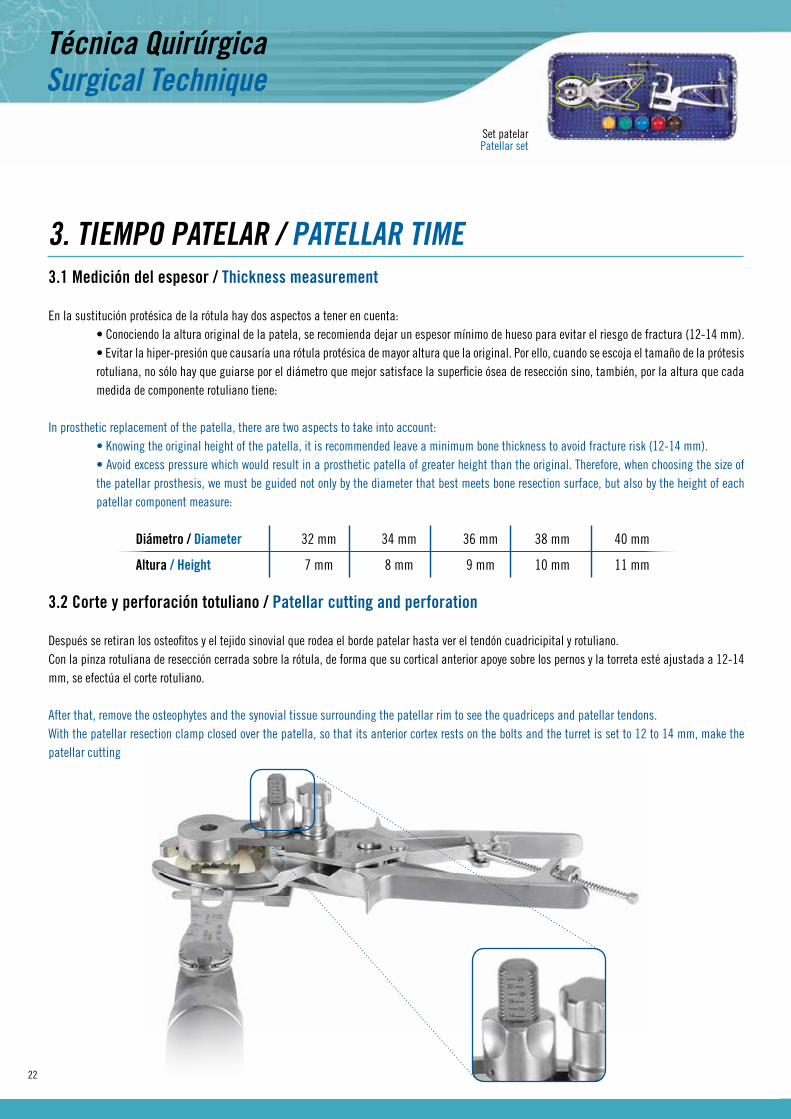
3. TIEMPO PATELAR / PATELLAR TIME3.1 Medición del espesor / Thickness measurement
En la sustitución protésica de la rótula hay dos aspectos a tener en cuenta: • Conociendo la altura original de la patela, se recomienda dejar un espesor mínimo de hueso para evitar el riesgo de fractura (12-14 mm). • Evitar la hiper-presión que causaría una rótula protésica de mayor altura que la original. Por ello, cuando se escoja el tamaño de la prótesis rotuliana, no sólo hay que guiarse por el diámetro que mejor satisface la superficie ósea de resección sino, también, por la altura que cada medida de componente rotuliano tiene:
In prosthetic replacement of the patella, there are two aspects to take into account: • Knowing the original height of the patella, it is recommended leave a minimum bone thickness to avoid fracture risk (12-14 mm). • Avoid excess pressure which would result in a prosthetic patella of greater height than the original. Therefore, when choosing the size of the patellar prosthesis, we must be guided not only by the diameter that best meets bone resection surface, but also by the height of each patellar component measure:
Diámetro / Diameter 32 mm 34 mm 36 mm 38 mm 40 mm
Altura / Height 7 mm 8 mm 9 mm 10 mm 11 mm
3.2 Corte y perforación totuliano / Patellar cutting and perforation
Después se retiran los osteofitos y el tejido sinovial que rodea el borde patelar hasta ver el tendón cuadricipital y rotuliano.Con la pinza rotuliana de resección cerrada sobre la rótula, de forma que su cortical anterior apoye sobre los pernos y la torreta esté ajustada a 12-14 mm, se efectúa el corte rotuliano.
After that, remove the osteophytes and the synovial tissue surrounding the patellar rim to see the quadriceps and patellar tendons.With the patellar resection clamp closed over the patella, so that its anterior cortex rests on the bolts and the turret is set to 12 to 14 mm, make the patellar cutting
23
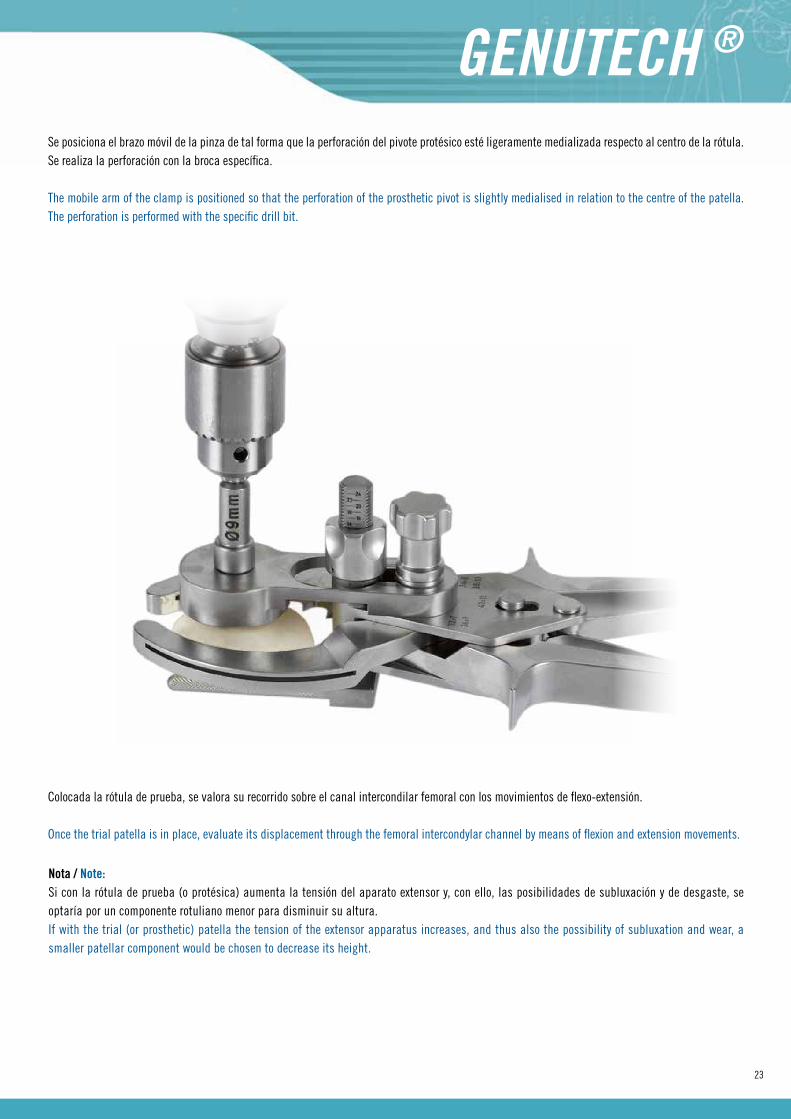
Se posiciona el brazo móvil de la pinza de tal forma que la perforación del pivote protésico esté ligeramente medializada respecto al centro de la rótula. Se realiza la perforación con la broca específica.
The mobile arm of the clamp is positioned so that the perforation of the prosthetic pivot is slightly medialised in relation to the centre of the patella. The perforation is performed with the specific drill bit.
Colocada la rótula de prueba, se valora su recorrido sobre el canal intercondilar femoral con los movimientos de flexo-extensión.
Once the trial patella is in place, evaluate its displacement through the femoral intercondylar channel by means of flexion and extension movements.
Nota / Note:Si con la rótula de prueba (o protésica) aumenta la tensión del aparato extensor y, con ello, las posibilidades de subluxación y de desgaste, se optaría por un componente rotuliano menor para disminuir su altura.If with the trial (or prosthetic) patella the tension of the extensor apparatus increases, and thus also the possibility of subluxation and wear, a smaller patellar component would be chosen to decrease its height.
24
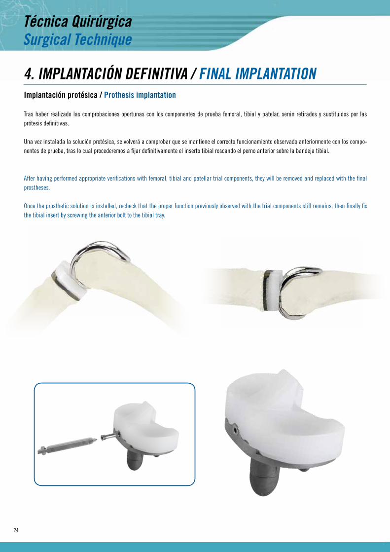
4. IMPLANTACIÓN DEFINITIVA / FINAL IMPLANTATIONImplantación protésica / Prothesis implantation
Tras haber realizado las comprobaciones oportunas con los componentes de prueba femoral, tibial y patelar, serán retirados y sustituidos por las prótesis definitivas.
Una vez instalada la solución protésica, se volverá a comprobar que se mantiene el correcto funcionamiento observado anteriormente con los compo-nentes de prueba, tras lo cual procederemos a fijar definitivamente el inserto tibial roscando el perno anterior sobre la bandeja tibial.
After having performed appropriate verifications with femoral, tibial and patellar trial components, they will be removed and replaced with the final prostheses.
Once the prosthetic solution is installed, recheck that the proper function previously observed with the trial components still remains; then finally fix the tibial insert by screwing the anterior bolt to the tibial tray.

25
ANEXOS / ANNEXES
26
ANEXO I / ANNEX I
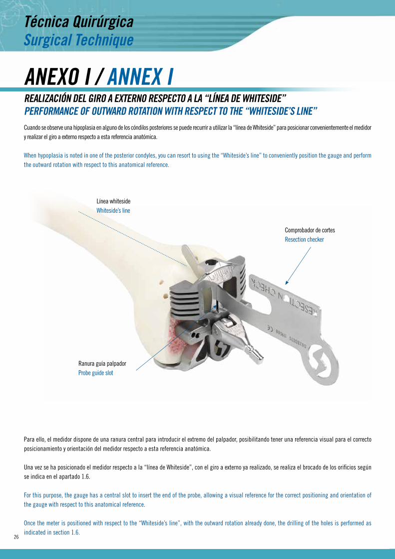
Cuando se observe una hipoplasia en alguno de los cóndilos posteriores se puede recurrir a utilizar la “línea de Whiteside” para posicionar convenientemente el medidor y realizar el giro a externo respecto a esta referencia anatómica.
When hypoplasia is noted in one of the posterior condyles, you can resort to using the “Whiteside’s line” to conveniently position the gauge and perform the outward rotation with respect to this anatomical reference.
REALIZACIÓN DEL GIRO A EXTERNO RESPECTO A LA “LÍNEA DE WHITESIDE”PERFORMANCE OF OUTWARD ROTATION WITH RESPECT TO THE “WHITESIDE’S LINE”
Ranura guía palpadorProbe guide slot
Comprobador de cortesResection checker
Línea whitesideWhiteside’s line
Para ello, el medidor dispone de una ranura central para introducir el extremo del palpador, posibilitando tener una referencia visual para el correcto posicionamiento y orientación del medidor respecto a esta referencia anatómica.
Una vez se ha posicionado el medidor respecto a la “línea de Whiteside”, con el giro a externo ya realizado, se realiza el brocado de los orificios según se indica en el apartado 1.6.
For this purpose, the gauge has a central slot to insert the end of the probe, allowing a visual reference for the correct positioning and orientation of the gauge with respect to this anatomical reference.
Once the meter is positioned with respect to the “Whiteside’s line”, with the outward rotation already done, the drilling of the holes is performed as indicated in section 1.6.
27
ANEXO 2 / ANNEX 2
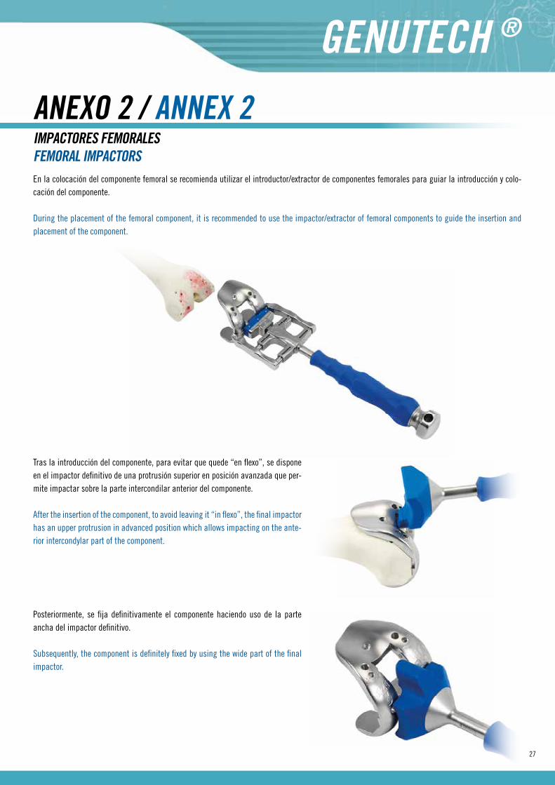
En la colocación del componente femoral se recomienda utilizar el introductor/extractor de componentes femorales para guiar la introducción y colo-cación del componente.
During the placement of the femoral component, it is recommended to use the impactor/extractor of femoral components to guide the insertion and placement of the component.
IMPACTORES FEMORALESFEMORAL IMPACTORS
Tras la introducción del componente, para evitar que quede “en flexo”, se dispone en el impactor definitivo de una protrusión superior en posición avanzada que per-mite impactar sobre la parte intercondilar anterior del componente.
After the insertion of the component, to avoid leaving it “in flexo”, the final impactor has an upper protrusion in advanced position which allows impacting on the ante-rior intercondylar part of the component.
Posteriormente, se fija definitivamente el componente haciendo uso de la parte ancha del impactor definitivo.
Subsequently, the component is definitely fixed by using the wide part of the final impactor.

28
El sistema Genutech® dispone de un impactor de bandeja y de un impactor de componente tibial. Este último permite impactar el componente comple-tamente montado sin dañar las zonas funcionales del inserto tibial.
The Genutech® system has a tray impactor and a tibial component impactor. The latter allows impacting the fully assembled component without da-maging the functional areas of the tibial insert.
IMPACTORES TIBIALESTIBIAL IMPACTORS
IMPACTOR DE BANDEJA TIBIAL / TIBIAL TRAY IMPACTOR IMPACTOR DE INSERTO TIBIAL / TIBIAL INSERT IMPACTOR
29
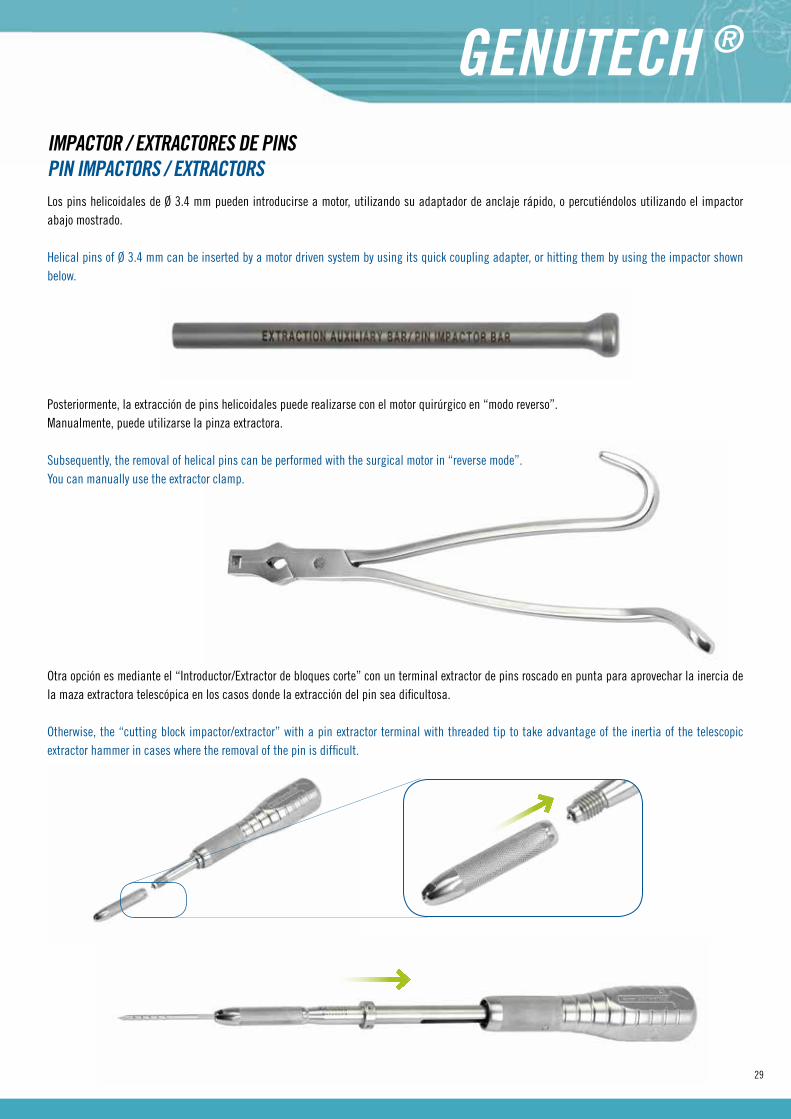
Los pins helicoidales de Ø 3.4 mm pueden introducirse a motor, utilizando su adaptador de anclaje rápido, o percutiéndolos utilizando el impactor abajo mostrado.
Helical pins of Ø 3.4 mm can be inserted by a motor driven system by using its quick coupling adapter, or hitting them by using the impactor shown below.
IMPACTOR / EXTRACTORES DE PINSPIN IMPACTORS / EXTRACTORS
Posteriormente, la extracción de pins helicoidales puede realizarse con el motor quirúrgico en “modo reverso”. Manualmente, puede utilizarse la pinza extractora.
Subsequently, the removal of helical pins can be performed with the surgical motor in “reverse mode”.You can manually use the extractor clamp.
Otra opción es mediante el “Introductor/Extractor de bloques corte” con un terminal extractor de pins roscado en punta para aprovechar la inercia de la maza extractora telescópica en los casos donde la extracción del pin sea dificultosa.
Otherwise, the “cutting block impactor/extractor” with a pin extractor terminal with threaded tip to take advantage of the inertia of the telescopic extractor hammer in cases where the removal of the pin is difficult.

30
ANEXO 3 / ANNEX 3
Cuando se introducen en flexión y en extensión los espaciadores pueden darse las siguientes situaciones: · NO ENTRA EN FLEXIÓN NI EN EXTENSIÓN.
Se aconseja efectuar un recorte adicional de 2 mm en tibia (por esta razón no es aconsejable retirar los pins de fijación de la guía de corte tibial hasta haber llegado a este punto, ya que únicamente se tiene que introducir la máscara a través de la línea de orificios marcada con “+2”). Con ello, se desciende la posición de la guía de corte 2 mm con respecto a la posición “0” sobre la que inicialmente se realizó el corte tibial.
When spacers are inserted in flexion and extension, following situations may arise: · IT DOES NOT FIT NEITHER IN FLEXION NOR IN EXTENSION.
It is advisable to make an additional cut of 2 mm on the tibia (for this reason, it is not advisable to remove the fixation pins from the tibial cutting guide until having reached this point, since you only need to insert the mask through the line of holes marked with “+2”). With this, the position of the cutting guide descends 2 mm from the “0” position on which the tibial cut was initially made.
REALIZACIÓN DE “RECUTS”PERFORMANCE OF “RECUTS”
PINS EN POSICIÓN “0” / POSITION PIN “0” PINS EN POSICIÓN “+2” (RECUT) / POSITION PINS “+2” (RECUT)
2 mm.
Antes de efectuar el corte con la sierra, se vuelve a colocar el pin o los pins oblicuos con cabeza para evitar la movilización que sobre la guía de corte puede producir la vibración de la sierra.
Before making the cut with the saw, the head oblique pin or pins are placed again to prevent mobilization that may be caused by saw vibration on the cutting guide.
· ENTRA EN EXTENSIÓN NO EN FLEXIÓN.
Se aconseja valorar una desinserción de la cápsula posterior del fémur o escoger una talla femoral más pequeña (sobre todo en los casos que se quiera conservar el ligamento cruzado posterior, ya que éste no puede desinsertarse). En este último caso, sobre los orificios precedentes realizados con la pieza para de medición femoral y giro a externo (ver Apdo. 1.6), se introduce una guía de brocado para realizar un segundo par de orificios distanciados 4 mm en altura de los primeros. Sobre ellos, se introduce el bloque de corte femoral de talla inferior y se repasan los planos de corte.
31
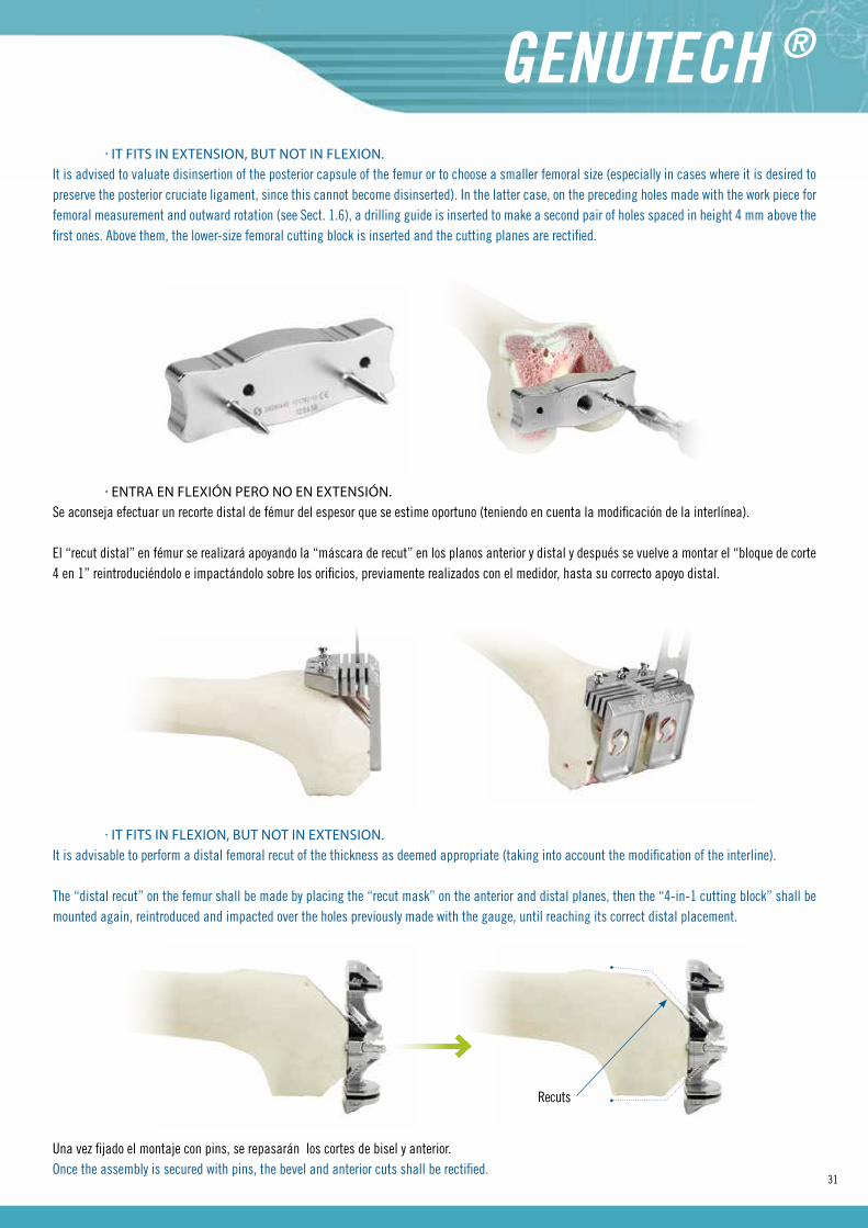
· IT FITS IN EXTENSION, BUT NOT IN FLEXION.It is advised to valuate disinsertion of the posterior capsule of the femur or to choose a smaller femoral size (especially in cases where it is desired to preserve the posterior cruciate ligament, since this cannot become disinserted). In the latter case, on the preceding holes made with the work piece for femoral measurement and outward rotation (see Sect. 1.6), a drilling guide is inserted to make a second pair of holes spaced in height 4 mm above the first ones. Above them, the lower-size femoral cutting block is inserted and the cutting planes are rectified.
· IT FITS IN FLEXION, BUT NOT IN EXTENSION.It is advisable to perform a distal femoral recut of the thickness as deemed appropriate (taking into account the modification of the interline).
The “distal recut” on the femur shall be made by placing the “recut mask” on the anterior and distal planes, then the “4-in-1 cutting block” shall be mounted again, reintroduced and impacted over the holes previously made with the gauge, until reaching its correct distal placement.
Recuts
Una vez fijado el montaje con pins, se repasarán los cortes de bisel y anterior. Once the assembly is secured with pins, the bevel and anterior cuts shall be rectified.
· ENTRA EN FLEXIÓN PERO NO EN EXTENSIÓN.Se aconseja efectuar un recorte distal de fémur del espesor que se estime oportuno (teniendo en cuenta la modificación de la interlínea).
El “recut distal” en fémur se realizará apoyando la “máscara de recut” en los planos anterior y distal y después se vuelve a montar el “bloque de corte 4 en 1” reintroduciéndolo e impactándolo sobre los orificios, previamente realizados con el medidor, hasta su correcto apoyo distal.

32
· ENTRA EN FLEXIÓN Y EN EXTENSIÓN PERO EL COMPONENTE FEMORAL SOBRESALE DE LA RESECCIÓN.
En los casos donde exista una tensión ligamentaria adecuada, tanto en flexión como en extensión, pero se observe que el componente femoral de prueba sobresale anteroposteriormente, mediolateralmente o sobre ciertas zonas determinadas, y se considere conveniente el solucionarlo reduciendo la talla del componente femoral, se podrá de forma sencilla reducir la talla del componente femoral a implantar por una inferior a la inicialmente seleccionada.
· IT FITS IN FLEXION AND EXTENSION, BUT THE FEMORAL COMPONENT PROTRUDES FROM THE RESECTION.
In cases where proper ligament tension exists in both flexion and extension, but there is evidence that the trial femoral component protrudes antero-posteriorly, mediolaterally or over determined areas, and it is deemed appropriate to fix this problem by downsizing the femoral component, you can in a simple way reduce the size of the femoral component to be implanted for one that is less than the initially selected.
Tan solo se deberá introducir un nuevo “bloque de corte 4 en 1”, de talla inferior a la inicialmente utilizada, a través de los orificios distales realizados durante la medición y giro a externo (Ver Apdos. 1.5 y 1.6).
Una vez fijado el bloque de corte, se repasarán los cortes anterior y de bisel.
You only need to insert a new “4-in-1 cutting block” of a size less than that initially used, through the distal holes made during the measurement and outward rotation (See sections 1.5 y 1.6).
Once the cutting block is secured with pins, the anterior and bevel cuts shall be rectified.

33
ANEXO 4 / ANNEX 4
El clipado se realiza de forma manual, apoyando primero la parte posterior del inserto sobre la bandeja tibial y presionando anteriormente ambas piezas.
Clipping is done manually, first supporting the back of the insert on the tibial tray and pressing previously on both parts.
CLIPADO Y EXTRACCIÓN DE INSERTOS TIBIALES / CLIPPING AND REMOVAL OF TIBIAL INSERTS
Para la extracción del inserto tibial, se introduce la punta plana del extractor en una de las ranuras que el inserto tibial deja al cliparse sobre la bandeja tibial, realizando un leve giro (no hacer palanca).
For the removal of the tibial insert, the flat tip of the remover is introduced into one of the slots left by the tibial insert when clipped on the tibial tray, performing a slight rotation (do not pry).
34
ANEXO 5 / ANNEX 5
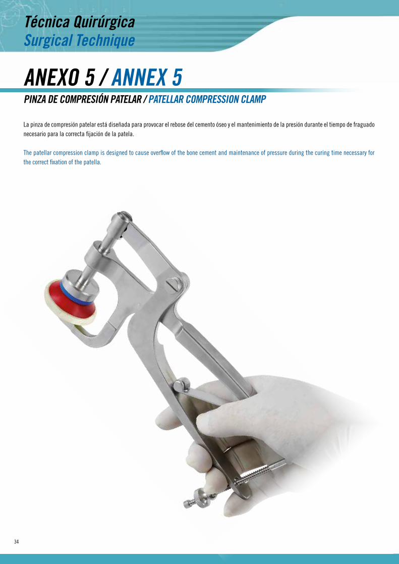
La pinza de compresión patelar está diseñada para provocar el rebose del cemento óseo y el mantenimiento de la presión durante el tiempo de fraguado necesario para la correcta fijación de la patela.
The patellar compression clamp is designed to cause overflow of the bone cement and maintenance of pressure during the curing time necessary for the correct fixation of the patella.
PINZA DE COMPRESIÓN PATELAR / PATELLAR COMPRESSION CLAMP
35
ANEXO 6 / ANNEX 6
ANEXO 7 / ANNEX 7
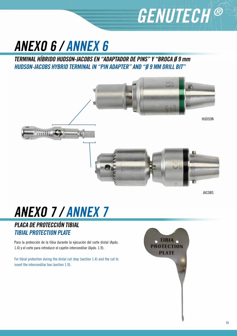
TERMINAL HÍBRIDO HUDSON-JACOBS EN “ADAPTADOR DE PINS” Y “BROCA Ø 9 mmHUDSON-JACOBS HYBRID TERMINAL IN “PIN ADAPTER” AND “Ø 9 MM DRILL BIT”
PLACA DE PROTECCIÓN TIBIALTIBIAL PROTECTION PLATE
HUDSON
JACOBS
Para la protección de la tibia durante la ejecución del corte distal (Apdo. 1.4) y el corte para introducir el cajetín intercondilar (Apdo. 1.9).
For tibial protection during the distal cut step (section 1.4) and the cut to insert the intercondilar box (section 1.9).
36
IMPLANTES / IMPLANTS
37
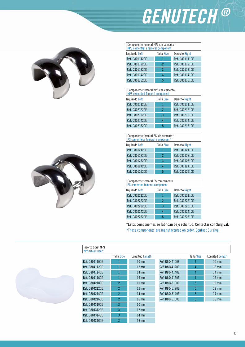
Componente femoral NPS sin cementoNPS cementless femoral component
Izquierdo Left Talla Size Derecho Right
Ref. D8011120E 1 Ref. D8011110E
Ref. D8011220E 2 Ref. D8011210E
Ref. D8011320E 3 Ref. D8011310E
Ref. D8011420E 4 Ref. D8011410E
Ref. D8011520E 5 Ref. D8011510E
Componente femoral PS sin cemento*PS cementless femoral component*
Izquierdo Left Talla Size Derecho Right
Ref. D8012120E 1 Ref. D8012110E
Ref. D8012220E 2 Ref. D8012210E
Ref. D8012320E 3 Ref. D8012310E
Ref. D8012420E 4 Ref. D8012410E
Ref. D8012520E 5 Ref. D8012510E
*Estos componentes se fabrican bajo solicitud. Contactar con Surgival. *These components are manufactured on order. Contact Surgival.
Componente femoral NPS con cementoNPS cemented femoral component
Izquierdo Left Talla Size Derecho Right
Ref. D8021120E 1 Ref. D8021110E
Ref. D8021220E 2 Ref. D8021210E
Ref. D8021320E 3 Ref. D8021310E
Ref. D8021420E 4 Ref. D8021410E
Ref. D8021520E 5 Ref. D8021510E
Componente femoral PS con cementoPS cemented femoral component
Izquierdo Left Talla Size Derecho Right
Ref. D8022120E 1 Ref. D8022110E
Ref. D8022220E 2 Ref. D8022210E
Ref. D8022320E 3 Ref. D8022310E
Ref. D8022420E 4 Ref. D8022410E
Ref. D8022520E 5 Ref. D8022510E
Inserto tibial NPSNPS tibial insert
Talla Size Longitud Length
Ref. D8041100E 1 10 mm
Ref. D8041120E 1 12 mm
Ref. D8041140E 1 14 mm
Ref. D8041160E 1 16 mm
Ref. D8042100E 2 10 mm
Ref. D8042120E 2 12 mm
Ref. D8042140E 2 14 mm
Ref. D8042160E 2 16 mm
Ref. D8043100E 3 10 mm
Ref. D8043120E 3 12 mm
Ref. D8043140E 3 14 mm
Ref. D8043160E 3 16 mm
Talla Size Longitud Length
Ref. D8044100E 4 10 mm
Ref. D8044120E 4 12 mm
Ref. D8044140E 4 14 mm
Ref. D8044160E 4 16 mm
Ref. D8045100E 5 10 mm
Ref. D8045120E 5 12 mm
Ref. D8045140E 5 14 mm
Ref. D8045160E 5 16 mm

38
ImplantsInserto tibial PSPS tibial insert
Talla Size Longitud Length
Ref. D8051100E 1 10 mm
Ref. D8051120E 1 12 mm
Ref. D8051140E 1 14 mm
Ref. D8051160E 1 16 mm
Ref. D8051180E 1 18 mm
Ref. D8051200E 1 20 mm
Ref. D8052100E 2 10 mm
Ref. D8052120E 2 12 mm
Ref. D8052140E 2 14 mm
Ref. D8052160E 2 16 mm
Ref. D8052180E 2 18 mm
Ref. D8052200E 2 20 mm
Ref. D8053100E 3 10 mm
Ref. D8053120E 3 12 mm
Ref. D8053140E 3 14 mm
Talla Size Longitud Length
Ref. D8053160E 3 16 mm
Ref. D8053180E 3 18 mm
Ref. D8053200E 3 20 mm
Ref. D8054100E 4 10 mm
Ref. D8054120E 4 12 mm
Ref. D8054140E 4 14 mm
Ref. D8054160E 4 16 mm
Ref. D8054180E 4 18 mm
Ref. D8054200E 4 20 mm
Ref. D8055100E 5 10 mm
Ref. D8055120E 5 12 mm
Ref. D8055140E 5 14 mm
Ref. D8055160E 5 16 mm
Ref. D8055180E 5 18 mm
Ref. D8055200E 5 20 mm
Bandeja tibialTibial tray
Talla Size
Ref. D8032100E 1
Ref. D8032200E 2
Ref. D8032300E 3
Ref. D8032400E 4
Ref. D8032500E 5
Perno de fijación *Fixation bolt *
Ref. D8220540
Tapón para bandeja tibialCap for tibial tray
Ref. D8032610E Corto/Short*
Ref. D8032620E Largo/ Long
Componente patelarPatellar component
Diámetro Diameter
Ref. D8030140E 32 mm
Ref. D8030150E 34 mm
Ref. D8030160E 36 mm
Ref. D8030170E 38 mm
Ref. D8030180E 40 mm
*Incluido en bandeja tibial.*Included with tibial tray.

39
INSTRUMENTAL / INSTRUMENTS
40
InstrumentsInstrumental
Bandeja superior / Upper tray
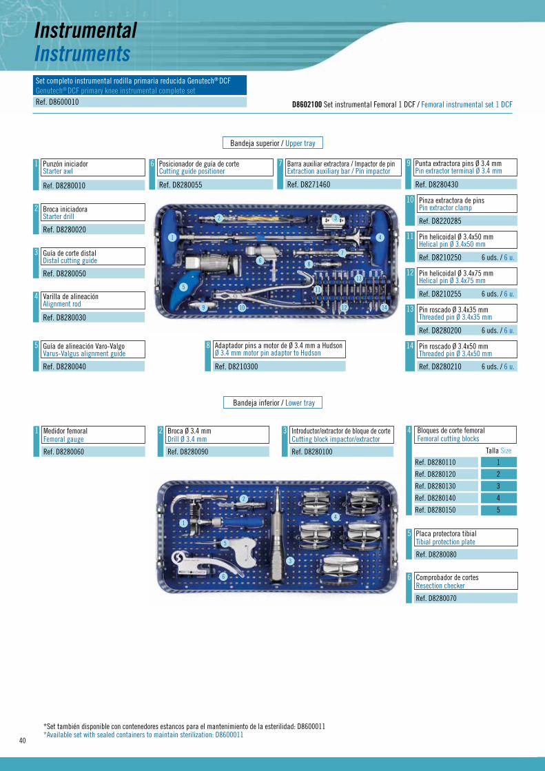
D8602100 Set instrumental Femoral 1 DCF / Femoral instrumental set 1 DCF
Set completo instrumental rodilla primaria reducida Genutech® DCFGenutech® DCF primary knee instrumental complete setRef. D8600010
Bandeja inferior / Lower tray
10 Pinza extractora de pinsPin extractor clamp
Ref. D8220285
1 Punzón iniciadorStarter awl
Ref. D8280010
2 Broca iniciadoraStarter drill
Ref. D8280020
3 Guía de corte distalDistal cutting guide
Ref. D8280050
4 Varilla de alineaciónAlignment rod
Ref. D8280030
5 Guía de alineación Varo-ValgoVarus-Valgus alignment guide
Ref. D8280040
6 Posicionador de guía de corteCutting guide positioner
Ref. D8280055
7 Barra auxiliar extractora / Impactor de pinExtraction auxiliary bar / Pin impactor
Ref. D8271460
8 Adaptador pins a motor de Ø 3.4 mm a HudsonØ 3.4 mm motor pin adaptor to Hudson
Ref. D8210300
9 Punta extractora pins Ø 3.4 mmPin extractor terminal Ø 3.4 mm
Ref. D8280430
Bloques de corte femoralFemoral cutting blocks
Talla Size
Ref. D8280110 1
Ref. D8280120 2
Ref. D8280130 3
Ref. D8280140 4
Ref. D8280150 5
41 Medidor femoralFemoral gauge
Ref. D8280060
2 Broca Ø 3.4 mmDrill Ø 3.4 mm
Ref. D8280090
3 Introductor/extractor de bloque de corteCutting block impactor/extractor
Ref. D8280100
5 Placa protectora tibialTibial protection plate
Ref. D8280080
6 Comprobador de cortesResection checker
Ref. D8280070
11 Pin helicoidal Ø 3.4x50 mmHelical pin Ø 3.4x50 mm
Ref. D8210250 6 uds. / 6 u.
12 Pin helicoidal Ø 3.4x75 mmHelical pin Ø 3.4x75 mm
Ref. D8210255 6 uds. / 6 u.
13 Pin roscado Ø 3.4x35 mmThreaded pin Ø 3.4x35 mm
Ref. D8280200 6 uds. / 6 u.
14 Pin roscado Ø 3.4x50 mmThreaded pin Ø 3.4x50 mm
Ref. D8280210 6 uds. / 6 u.
1
1
2
5
6
3
4
2 3
4
5
67
8
9 10
11
12
13
14
*Set también disponible con contenedores estancos para el mantenimiento de la esterilidad: D8600011*Available set with sealed containers to maintain sterilization: D8600011

41
Bandeja superior / Upper tray
D8602200 Set instrumental femoral 2 DCF / Femoral instrumental set 2 DCF
Bandeja inferior / Lower tray
2 Broca para tetones NPSNPS drill bit
Ref. D8280410 Cajetín intercondilar de prueba PSPS trial intercondylar box
Talla Size
Ref. D8280310 1
Ref. D8280320 2
Ref. D8280330 3
Ref. D8280340 4
Ref. D8280350 5
5
1
3
2
4
5
Introductor/extractor componentes femoralesImpactor/extractor of femoral components
Bloque recut posterior + 4 mmPosterior recut block + 4 mm
Destornillador hexagonal 4.5 mmHexagonal screwdriver 4.5 mm
Bloque de recut distalRecutting distal block
Impactor componente femoralFemoral component impactor
Ref. D8280360
Ref. D8280440
Ref. D8220630
Ref. D8272165
Ref. D8280370
Componentes femorales de pruebaTrial femoral components
Talla SizeDerecho Right Izquierdo Left
Ref. D8114110 1
Ref. D8114210 2
Ref. D8114310 3
Ref. D8114410 4
Ref. D8114510 5
Ref. D8114120
Ref. D8114220
Ref. D8114320
Ref. D8114420
Ref. D8114520
1
3 Pin con cabeza Ø 3.4x40 mmPin with head Ø 3.4x40 mm
Ref. D8210162 4 uds. / 4 u.
4 Guía sierra intercondilarIntercondilar cutting guide
Ref. D8280380
6 CincelChisel
Ref. D8280420
1
1
3 4
5
2
2 3
4
5
6
42
InstrumentsInstrumental
Bandeja superior / Upper tray
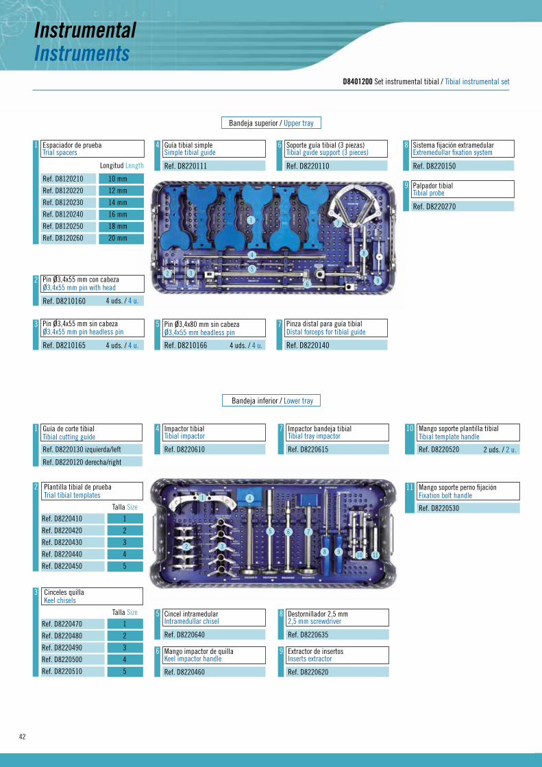
D8401200 Set instrumental tibial / Tibial instrumental set
Bandeja inferior / Lower tray
1 Guía de corte tibialTibial cutting guide
Ref. D8220130 izquierda/left
Ref. D8220120 derecha/right
10 Mango soporte plantilla tibialTibial template handle
Ref. D8220520
1 Espaciador de pruebaTrial spacers
Longitud Length
Ref. D8120210 10 mm
Ref. D8120220 12 mm
Ref. D8120230 14 mm
Ref. D8120240 16 mm
Ref. D8120250 18 mm
Ref. D8120260 20 mm
2 Pin ø3,4x55 mm con cabezaø3,4x55 mm pin with head
Ref. D8210160
3 Pin ø3,4x55 mm sin cabezaø3,4x55 mm pin headless pin
Ref. D8210165
4 Guía tibial simpleSimple tibial guide
Ref. D8220111
5 Pin ø3,4x80 mm sin cabezaø3,4x55 mm headless pin
Ref. D8210166
6 Soporte guía tibial (3 piezas)Tibial guide support (3 pieces)
Ref. D8220110
7 Pinza distal para guía tibialDistal forceps for tibial guide
Ref. D8220140
8 Sistema fijación extramedularExtremedullar fixation system
Ref. D8220150
9 Palpador tibialTibial probe
Ref. D8220270
1
2 3
4
5
6
7
8
9
Plantilla tibial de pruebaTrial tibial templates
Talla Size
Ref. D8220410 1
Ref. D8220420 2
Ref. D8220430 3
Ref. D8220440 4
Ref. D8220450 5
2
Cinceles quillaKeel chisels
Talla Size
Ref. D8220470 1
Ref. D8220480 2
Ref. D8220490 3
Ref. D8220500 4
Ref. D8220510 5
3
4 Impactor tibialTibial impactor
Ref. D8220610
5 Cincel intramedularIntramedullar chisel
Ref. D8220640
6 Mango impactor de quillaKeel impactor handle
Ref. D8220460
7 Impactor bandeja tibialTibial tray impactor
Ref. D8220615
8 Destornillador 2,5 mm2,5 mm screwdriver
Ref. D8220635
9 Extractor de insertosInserts extractor
Ref. D8220620
11 Mango soporte perno fijaciónFixation bolt handle
Ref. D82205301
2 3
4
5 6 7
8 9 10 11
2 uds. / 2 u.
4 uds. / 4 u.4 uds. / 4 u.
4 uds. / 4 u.
43
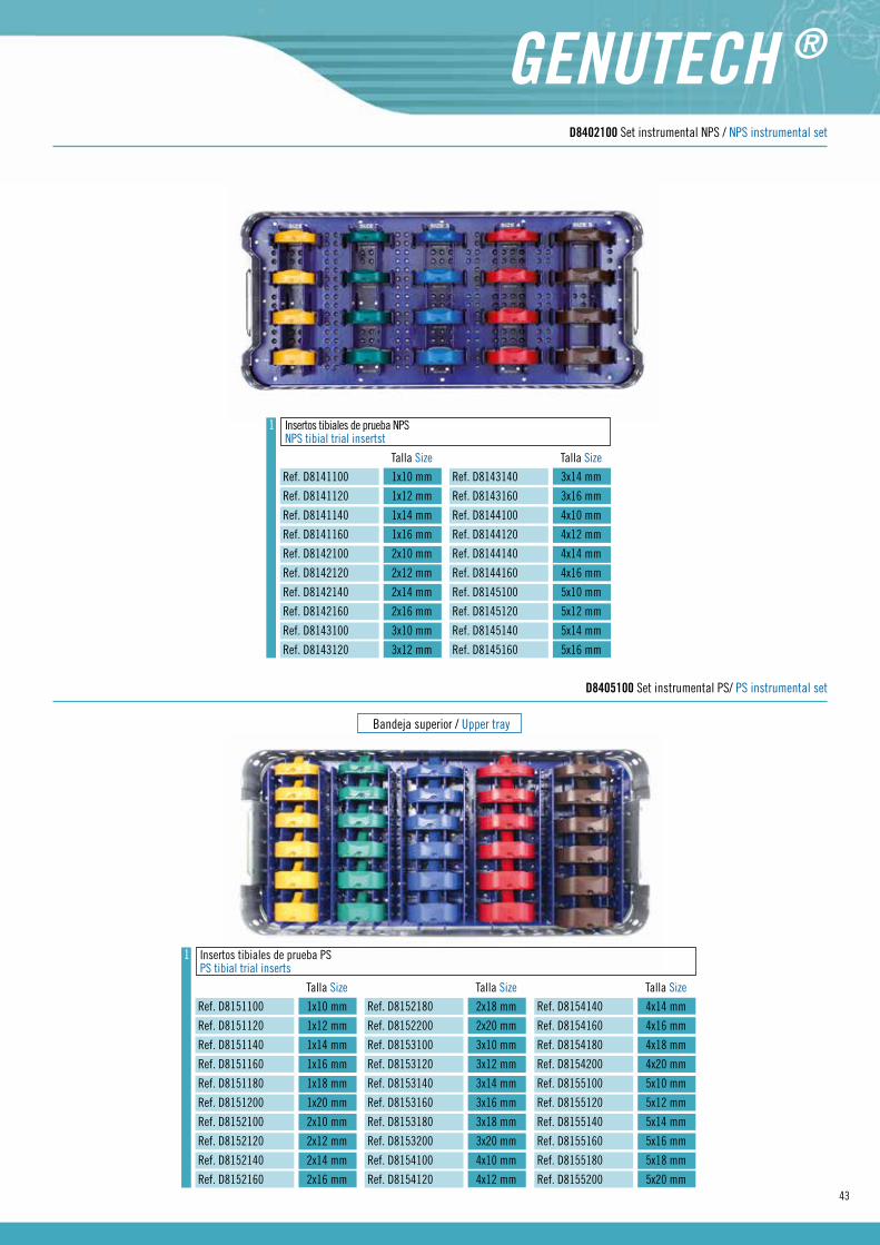
Insertos tibiales de prueba NPSNPS tibial trial insertst
Talla Size
Ref. D8141100 1x10 mm
Ref. D8141120 1x12 mm
Ref. D8141140 1x14 mm
Ref. D8141160 1x16 mm
Ref. D8142100 2x10 mm
Ref. D8142120 2x12 mm
Ref. D8142140 2x14 mm
Ref. D8142160 2x16 mm
Ref. D8143100 3x10 mm
Ref. D8143120 3x12 mm
1
Talla Size
Ref. D8143140 3x14 mm
Ref. D8143160 3x16 mm
Ref. D8144100 4x10 mm
Ref. D8144120 4x12 mm
Ref. D8144140 4x14 mm
Ref. D8144160 4x16 mm
Ref. D8145100 5x10 mm
Ref. D8145120 5x12 mm
Ref. D8145140 5x14 mm
Ref. D8145160 5x16 mm
D8402100 Set instrumental NPS / NPS instrumental set
Bandeja superior / Upper tray
Insertos tibiales de prueba PSPS tibial trial inserts
Talla Size
Ref. D8151100 1x10 mm
Ref. D8151120 1x12 mm
Ref. D8151140 1x14 mm
Ref. D8151160 1x16 mm
Ref. D8151180 1x18 mm
Ref. D8151200 1x20 mm
Ref. D8152100 2x10 mm
Ref. D8152120 2x12 mm
Ref. D8152140 2x14 mm
Ref. D8152160 2x16 mm
Talla Size
Ref. D8152180 2x18 mm
Ref. D8152200 2x20 mm
Ref. D8153100 3x10 mm
Ref. D8153120 3x12 mm
Ref. D8153140 3x14 mm
Ref. D8153160 3x16 mm
Ref. D8153180 3x18 mm
Ref. D8153200 3x20 mm
Ref. D8154100 4x10 mm
Ref. D8154120 4x12 mm
Talla Size
Ref. D8154140 4x14 mm
Ref. D8154160 4x16 mm
Ref. D8154180 4x18 mm
Ref. D8154200 4x20 mm
Ref. D8155100 5x10 mm
Ref. D8155120 5x12 mm
Ref. D8155140 5x14 mm
Ref. D8155160 5x16 mm
Ref. D8155180 5x18 mm
Ref. D8155200 5x20 mm
1
D8405100 Set instrumental PS/ PS instrumental set
44
InstrumentsInstrumental
Bandeja superior / Upper tray
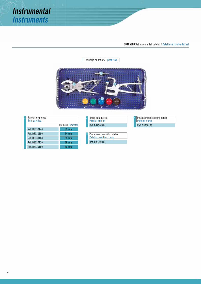
D8405300 Set intrumental patelar / Patellar instrumental set
Patelas de pruebaTrial patellas
Diámetro Diameter
Ref. D8130140 32 mm
Ref. D8130150 34 mm
Ref. D8130160 36 mm
Ref. D8130170 38 mm
Ref. D8130180 40 mm
1 2 Broca para patelaPatellar drill bit
Ref. D8230120
3 Pinza para resección patelarPatellar resection clamp
Ref. D8230110
4 Pinza abrazadera para patelaPatellar clamp
Ref. D8230130
1
2
3 4

45

46


IROG
EFTQ
01 /
07-2
015
© R
ev. 1