Instrument Series Webinar - Switches 2india.ni.com/sites/default/files/Large Channel Count Switching...
65
ni.com
Transcript of Instrument Series Webinar - Switches 2india.ni.com/sites/default/files/Large Channel Count Switching...

ni.com
National Instruments Switches
ni.com | NI CONFIDENTIAL
Raviteja Chivukula
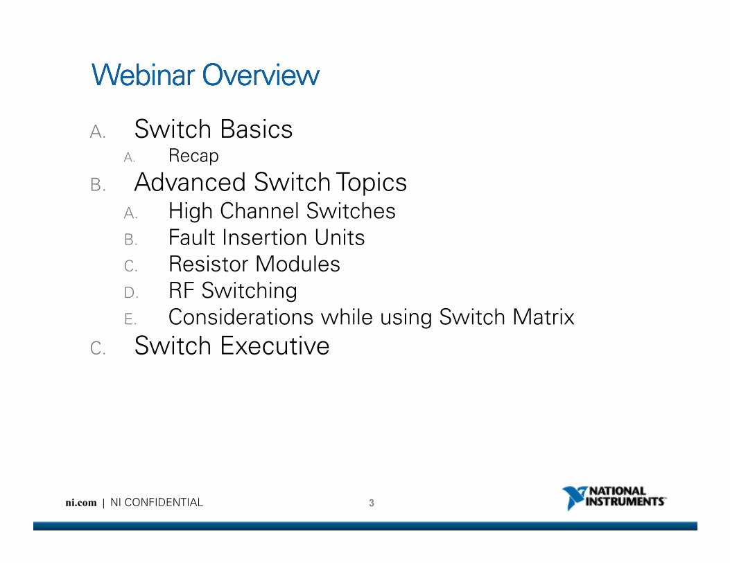
Webinar OverviewWebinar OverviewWebinar OverviewWebinar Overview
A. Switch BasicsA. Recap
B. Advanced Switch TopicsA. High Channel Switches
B. Fault Insertion Units
C. Resistor Modules
RF Switching
3ni.com | NI CONFIDENTIAL
D. RF Switching
E. Considerations while using Switch Matrix
C. Switch Executive
Switch Basics
ni.com | NI CONFIDENTIAL
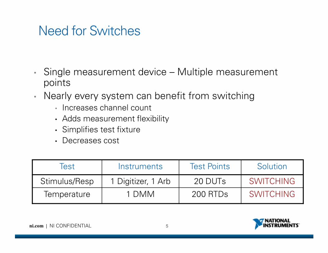
Need for Switches
• Single measurement device – Multiple measurement points
• Nearly every system can benefit from switching• Increases channel count
• Adds measurement flexibility
Simplifies test fixture
5ni.com | NI CONFIDENTIAL
• Simplifies test fixture
• Decreases cost
Test Instruments Test Points Solution
Stimulus/Resp 1 Digitizer, 1 Arb 20 DUTs SWITCHING
Temperature 1 DMM 200 RTDs SWITCHING
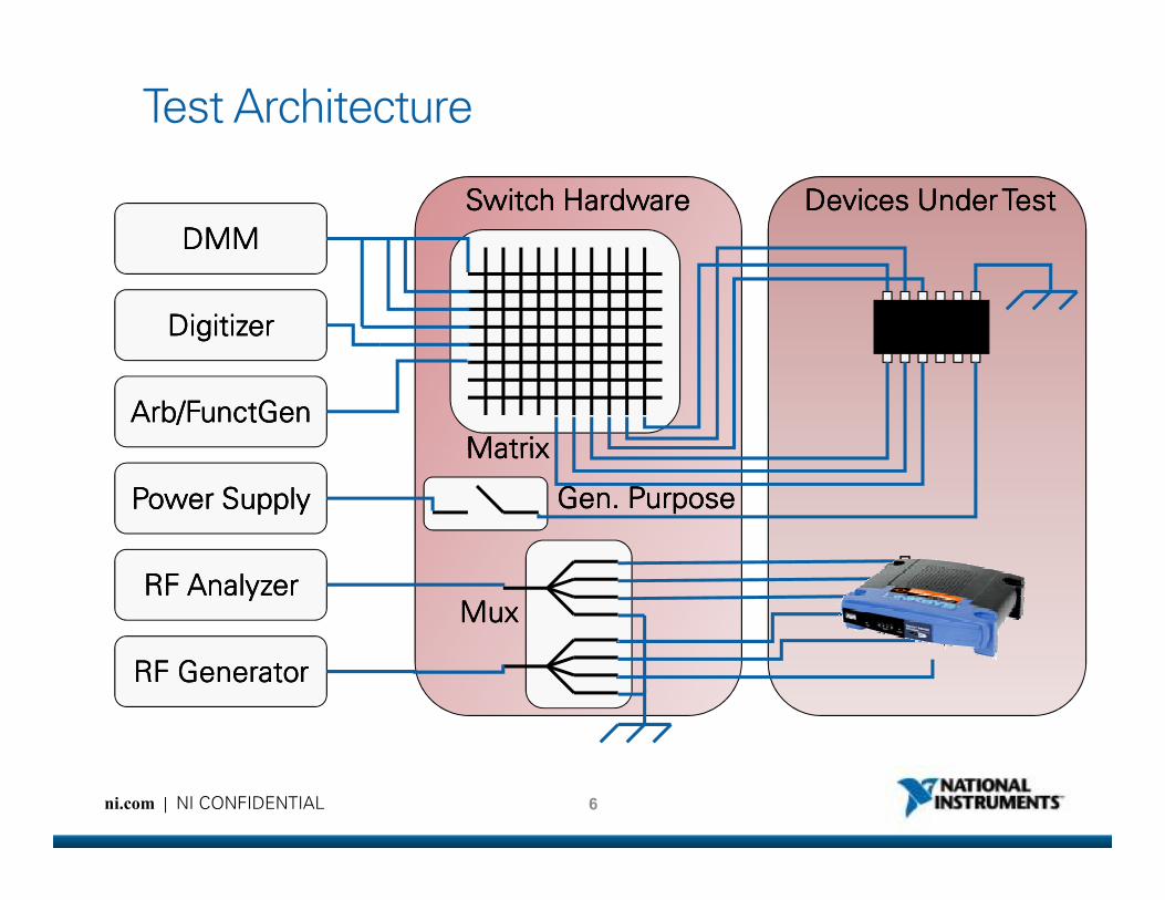
Test Architecture
DMMDMMDMMDMM
ArbArbArbArb////FunctGenFunctGenFunctGenFunctGen
DigitizerDigitizerDigitizerDigitizer
Devices Under TestDevices Under TestDevices Under TestDevices Under TestSwitch HardwareSwitch HardwareSwitch HardwareSwitch Hardware
MatrixMatrixMatrixMatrix
6ni.com | NI CONFIDENTIAL
RFRFRFRF AnalyzerAnalyzerAnalyzerAnalyzer
PowerPowerPowerPower SupplySupplySupplySupply
RFRFRFRF GeneratorGeneratorGeneratorGenerator
MatrixMatrixMatrixMatrix
Gen. PurposeGen. PurposeGen. PurposeGen. Purpose
MuxMuxMuxMux
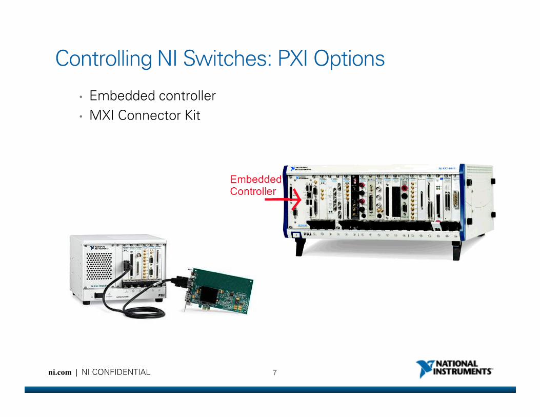
Controlling NI Switches: PXI Options
• Embedded controller
• MXI Connector Kit
7ni.com | NI CONFIDENTIAL
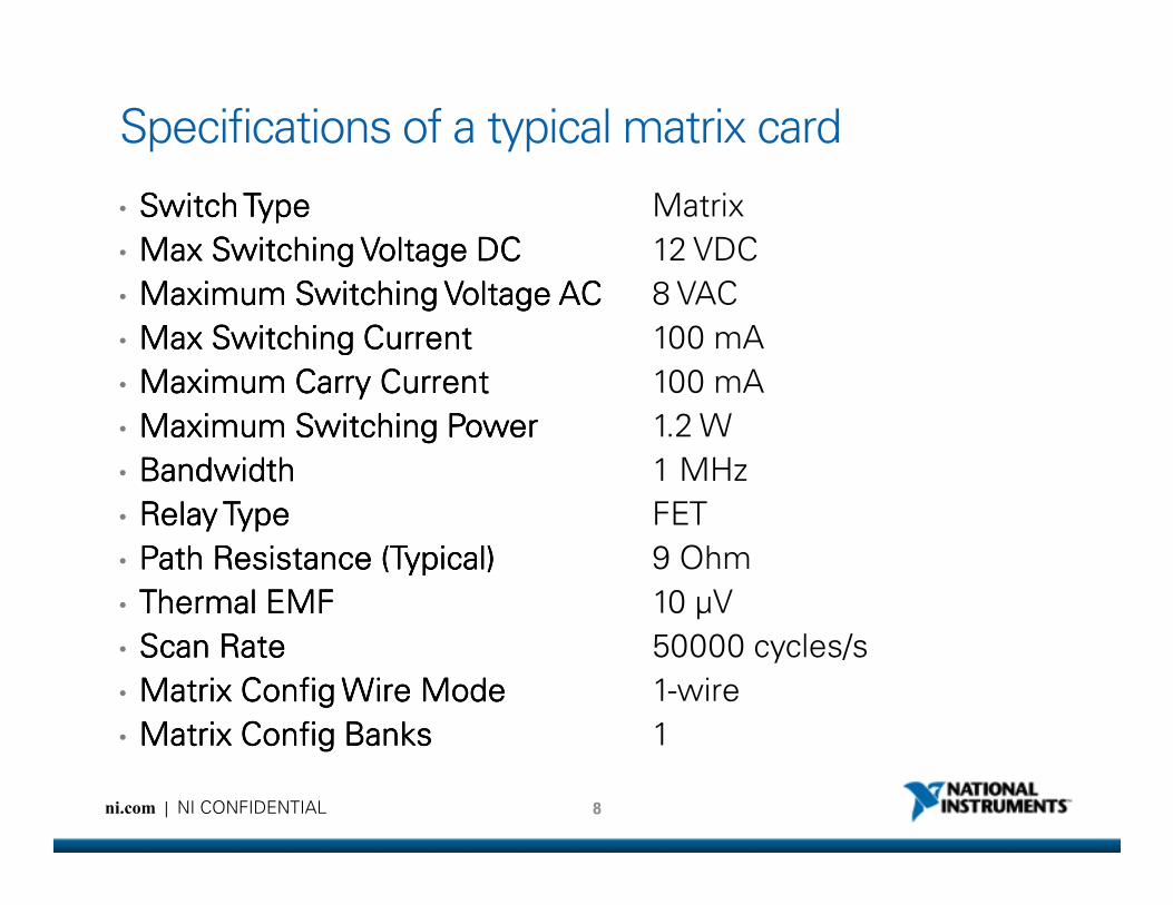
Specifications of a typical matrix card
• Switch TypeSwitch TypeSwitch TypeSwitch Type Matrix
• Max Switching Voltage DCMax Switching Voltage DCMax Switching Voltage DCMax Switching Voltage DC 12 VDC
• Maximum Switching Voltage ACMaximum Switching Voltage ACMaximum Switching Voltage ACMaximum Switching Voltage AC 8 VAC
• Max Switching CurrentMax Switching CurrentMax Switching CurrentMax Switching Current 100 mA
• Maximum Carry CurrentMaximum Carry CurrentMaximum Carry CurrentMaximum Carry Current 100 mA
• Maximum Switching PowerMaximum Switching PowerMaximum Switching PowerMaximum Switching Power 1.2 W
BandwidthBandwidthBandwidthBandwidth 1 MHz
8ni.com | NI CONFIDENTIAL
• BandwidthBandwidthBandwidthBandwidth 1 MHz
• Relay TypeRelay TypeRelay TypeRelay Type FET
• Path Resistance (Typical)Path Resistance (Typical)Path Resistance (Typical)Path Resistance (Typical) 9 Ohm
• Thermal EMFThermal EMFThermal EMFThermal EMF 10 µV
• Scan RateScan RateScan RateScan Rate 50000 cycles/s
• Matrix Config Wire ModeMatrix Config Wire ModeMatrix Config Wire ModeMatrix Config Wire Mode 1-wire
• Matrix Config BanksMatrix Config BanksMatrix Config BanksMatrix Config Banks 1
Advanced Switch Topics
ni.com | NI CONFIDENTIAL

High Channel Switches – Channel Expansion
ni.com | NI CONFIDENTIAL
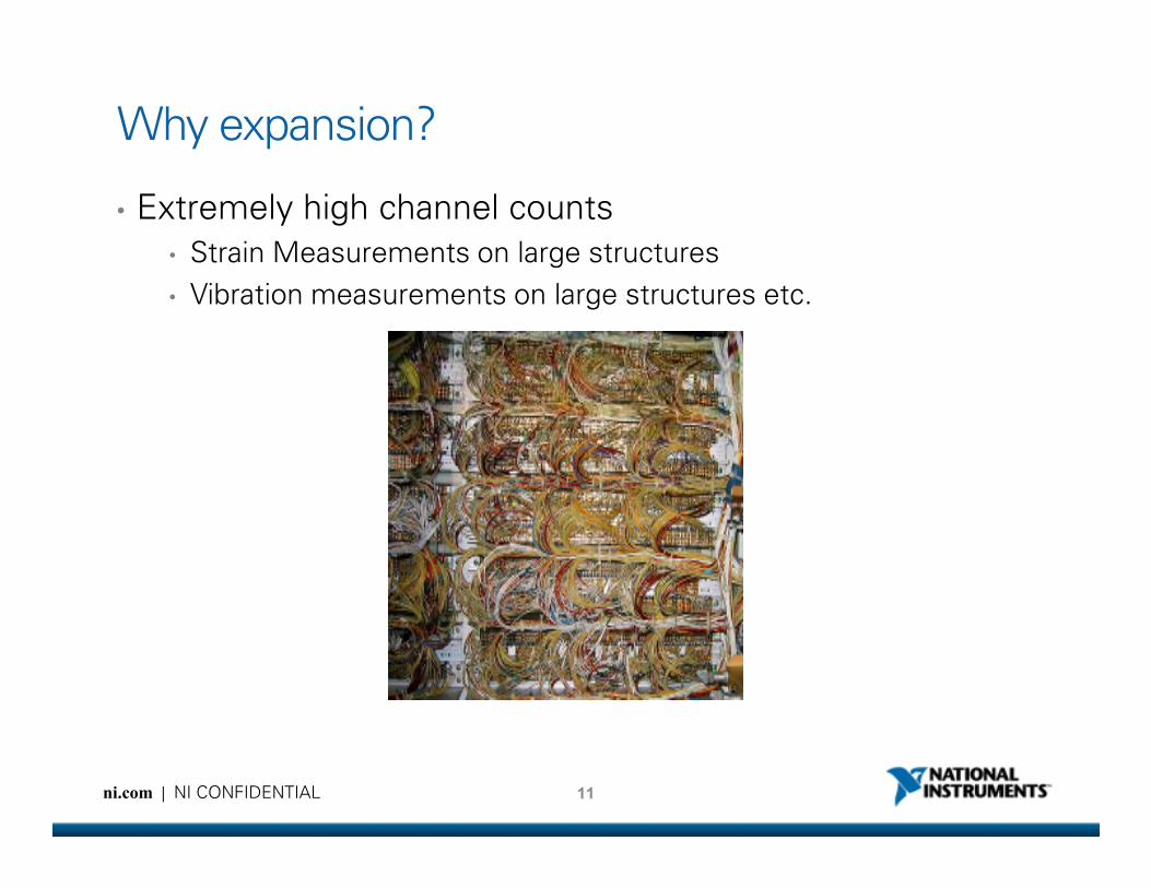
Why expansion?
• Extremely high channel counts
• Strain Measurements on large structures
• Vibration measurements on large structures etc.
11ni.com | NI CONFIDENTIAL
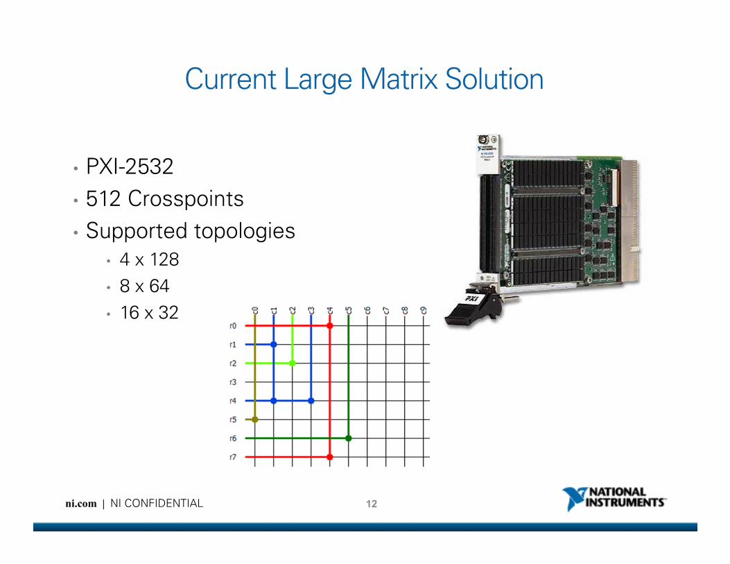
Current Large Matrix Solution
• PXI-2532
• 512 Crosspoints
• Supported topologies
• 4 x 128
• 8 x 64
12ni.com | NI CONFIDENTIAL
• 8 x 64
• 16 x 32
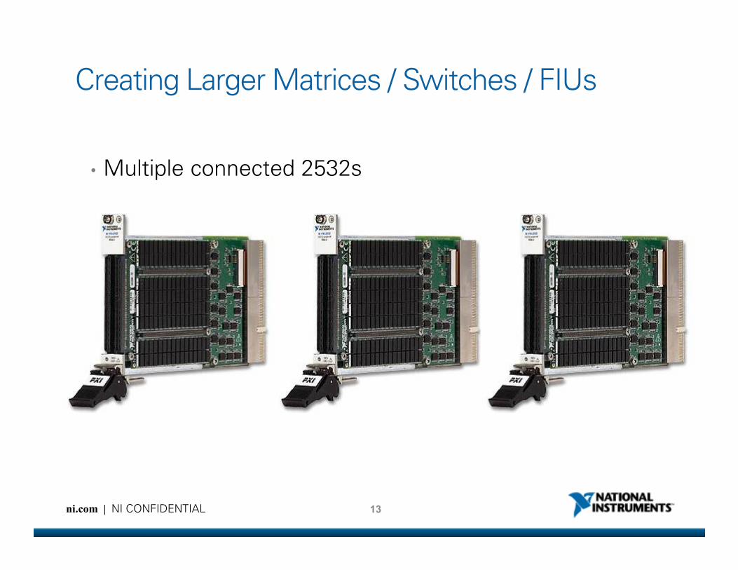
Creating Larger Matrices / Switches / FIUs
• Multiple connected 2532s
13ni.com | NI CONFIDENTIAL
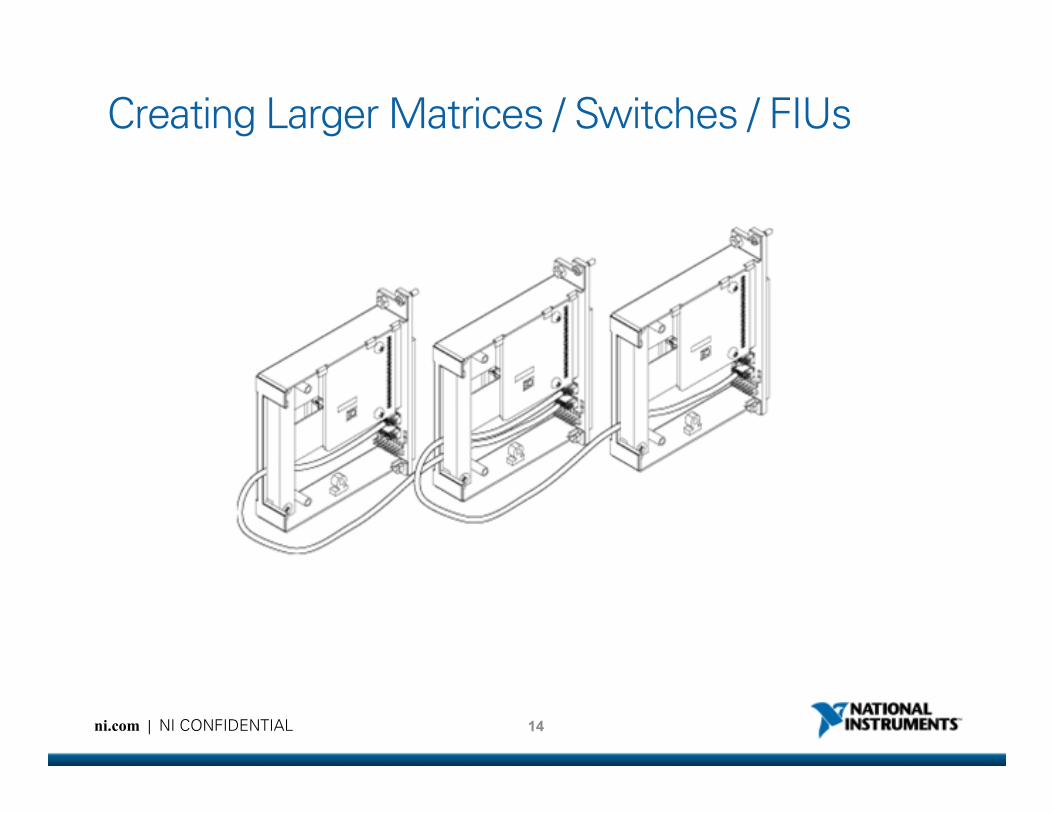
Creating Larger Matrices / Switches / FIUs
14ni.com | NI CONFIDENTIAL

• Expand the PXI-2529
columns using the TB-
2634
• Connect adjacent
terminal blocks with
ribbon cables
PXI Expansion: Matrices
15ni.com | NI CONFIDENTIAL
ribbon cables
Example:
PXI-2529
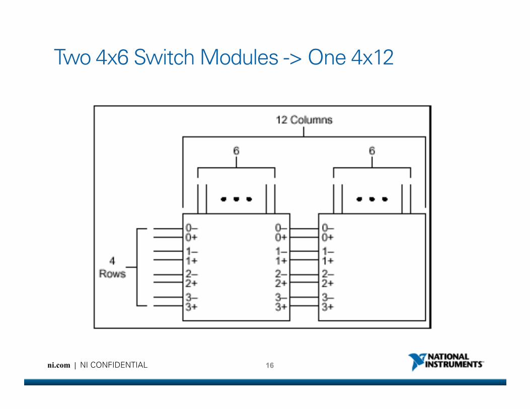
Two 4x6 Switch Modules -> One 4x12
16ni.com | NI CONFIDENTIAL
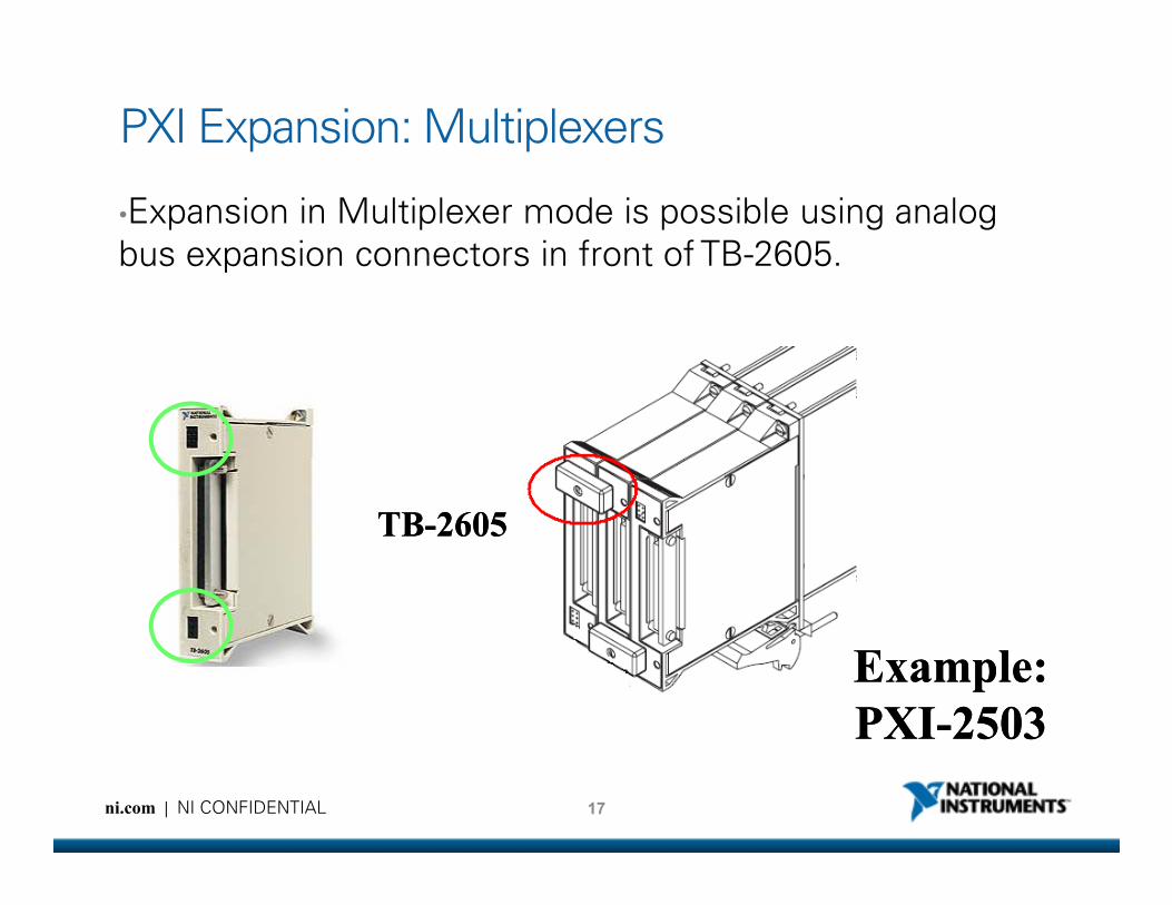
•Expansion in Multiplexer mode is possible using analog
bus expansion connectors in front of TB-2605.
PXI Expansion: Multiplexers
17ni.com | NI CONFIDENTIAL
TBTB--26052605
Example:Example:
PXIPXI--25032503

• Column expansion using
SHC68-C68-S cable
• No row expansion
PXI Expansion: Matrices
18ni.com | NI CONFIDENTIAL
Example:Example:
PXIPXI--25352535
Fault Insertion Units
ni.com | NI CONFIDENTIAL
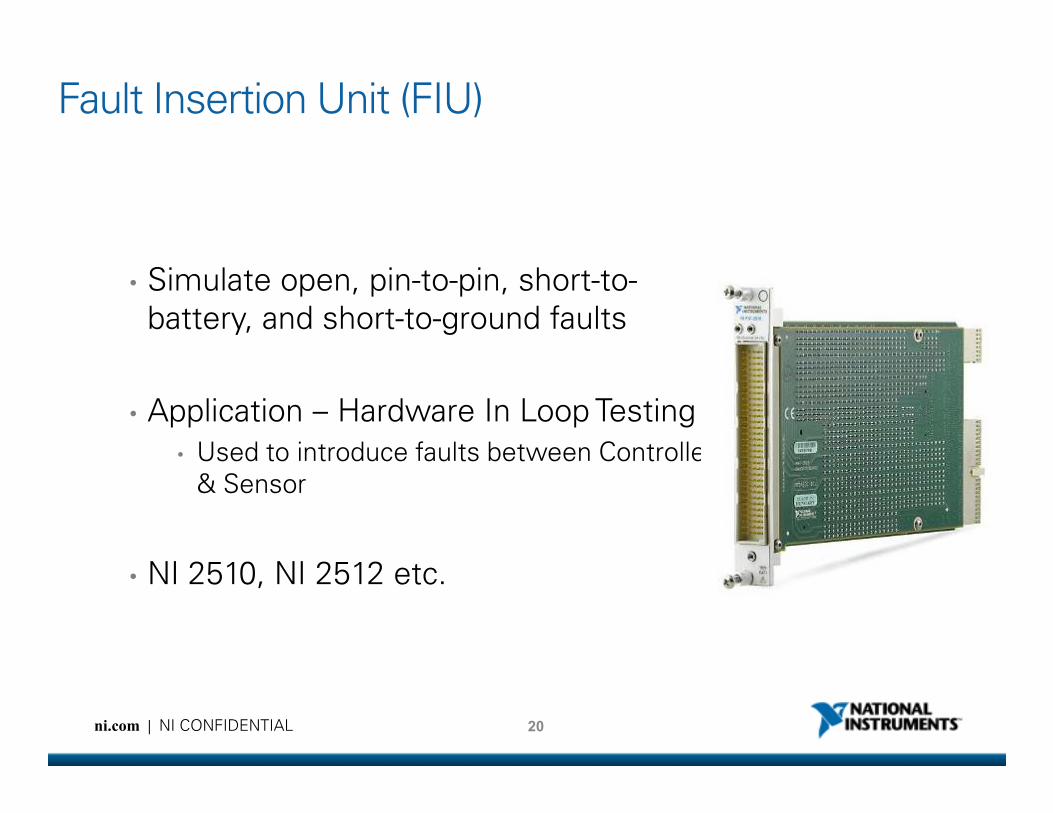
Fault Insertion Unit (FIU)
• Simulate open, pin-to-pin, short-to-
battery, and short-to-ground faults
• Application – Hardware In Loop Testing
20ni.com | NI CONFIDENTIAL
• Application – Hardware In Loop Testing
• Used to introduce faults between Controller
& Sensor
• NI 2510, NI 2512 etc.
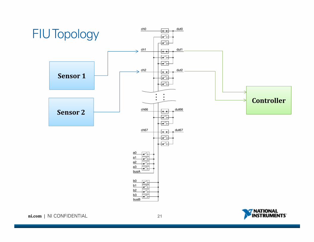
FIU Topology
Controller
Sensor 1
Sensor 2
21ni.com | NI CONFIDENTIAL
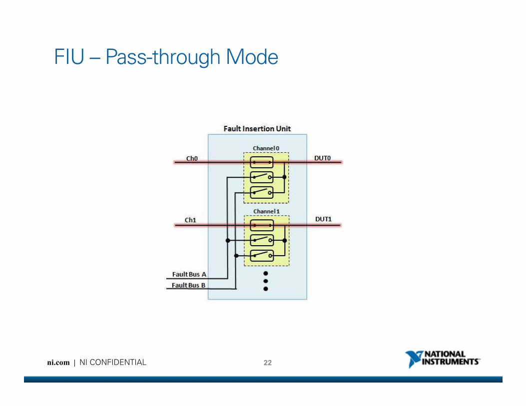
FIU – Pass-through Mode
22ni.com | NI CONFIDENTIAL

FIU – Open-circuit Fault
23ni.com | NI CONFIDENTIAL
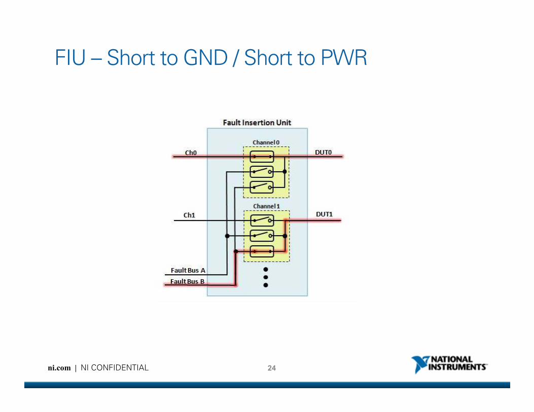
FIU – Short to GND / Short to PWR
24ni.com | NI CONFIDENTIAL
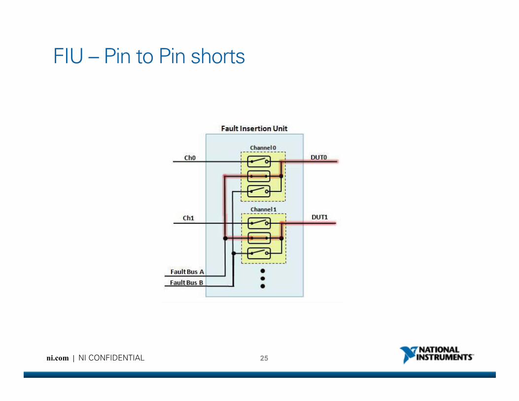
FIU – Pin to Pin shorts
25ni.com | NI CONFIDENTIAL
272x Resistor Modules
ni.com | NI CONFIDENTIAL
272x Design Overview272x Design Overview272x Design Overview272x Design Overview
27ni.com | NI CONFIDENTIAL
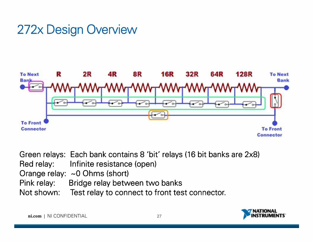
Green relays: Each bank contains 8 ‘bit’ relays (16 bit banks are 2x8)Green relays: Each bank contains 8 ‘bit’ relays (16 bit banks are 2x8)Green relays: Each bank contains 8 ‘bit’ relays (16 bit banks are 2x8)Green relays: Each bank contains 8 ‘bit’ relays (16 bit banks are 2x8)
Red relay: Infinite resistance (open)Red relay: Infinite resistance (open)Red relay: Infinite resistance (open)Red relay: Infinite resistance (open)
Orange relay: ~0 Ohms (short)Orange relay: ~0 Ohms (short)Orange relay: ~0 Ohms (short)Orange relay: ~0 Ohms (short)
Pink relay: Bridge relay between two banksPink relay: Bridge relay between two banksPink relay: Bridge relay between two banksPink relay: Bridge relay between two banks
Not shown: Test relay to connect to front test connector.Not shown: Test relay to connect to front test connector.Not shown: Test relay to connect to front test connector.Not shown: Test relay to connect to front test connector.
272x Design Overview (cont)272x Design Overview (cont)272x Design Overview (cont)272x Design Overview (cont)
By switching the “green” relays, you decrease the resistance of the
28ni.com | NI CONFIDENTIAL
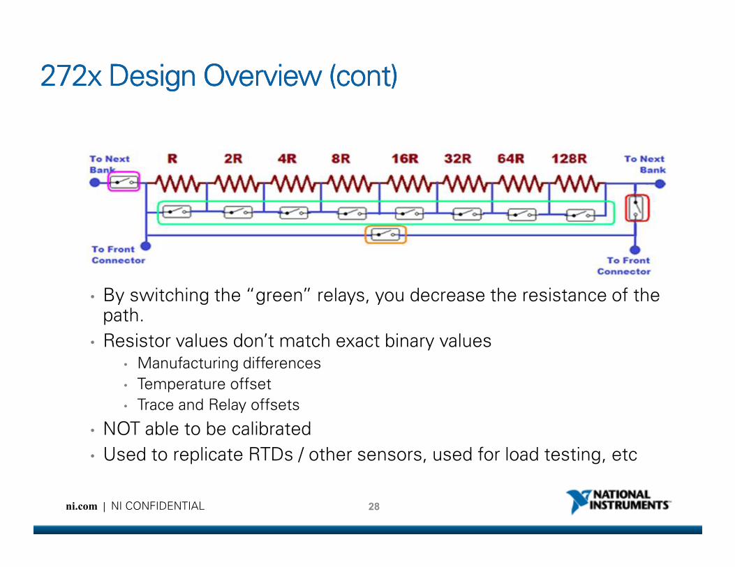
• By switching the “green” relays, you decrease the resistance of the path.
• Resistor values don’t match exact binary values • Manufacturing differences
• Temperature offset
• Trace and Relay offsets
• NOT able to be calibrated
• Used to replicate RTDs / other sensors, used for load testing, etc
NI 272x Applications
• RTD Simulation
• Other Sensor Simulation
• Resistive Load Simulation etc.
29ni.com | NI CONFIDENTIAL
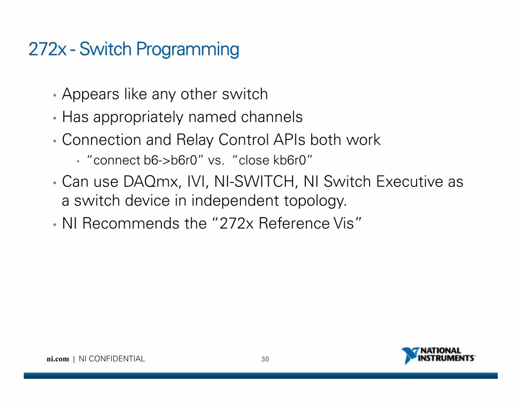
272x 272x 272x 272x ---- Switch ProgrammingSwitch ProgrammingSwitch ProgrammingSwitch Programming
• Appears like any other switch
• Has appropriately named channels
• Connection and Relay Control APIs both work
• “connect b6->b6r0” vs. “close kb6r0”
• Can use DAQmx, IVI, NI-SWITCH, NI Switch Executive as
a switch device in independent topology.
30ni.com | NI CONFIDENTIAL
a switch device in independent topology.
• NI Recommends the “272x Reference Vis”
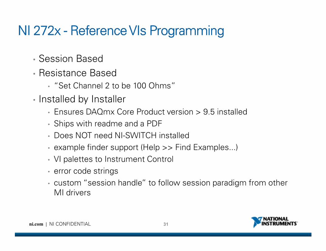
NI 272x NI 272x NI 272x NI 272x ---- Reference VIs ProgrammingReference VIs ProgrammingReference VIs ProgrammingReference VIs Programming
• Session Based
• Resistance Based
• “Set Channel 2 to be 100 Ohms”
• Installed by Installer
• Ensures DAQmx Core Product version > 9.5 installed
• Ships with readme and a PDF
31ni.com | NI CONFIDENTIAL
• Ships with readme and a PDF
• Does NOT need NI-SWITCH installed
• example finder support (Help >> Find Examples...)
• VI palettes to Instrument Control
• error code strings
• custom “session handle” to follow session paradigm from other
MI drivers

272x Example Block Diagram272x Example Block Diagram272x Example Block Diagram272x Example Block Diagram
32ni.com | NI CONFIDENTIAL
RF Switch Concepts
33ni.com | NI CONFIDENTIAL
RF Switch Concepts
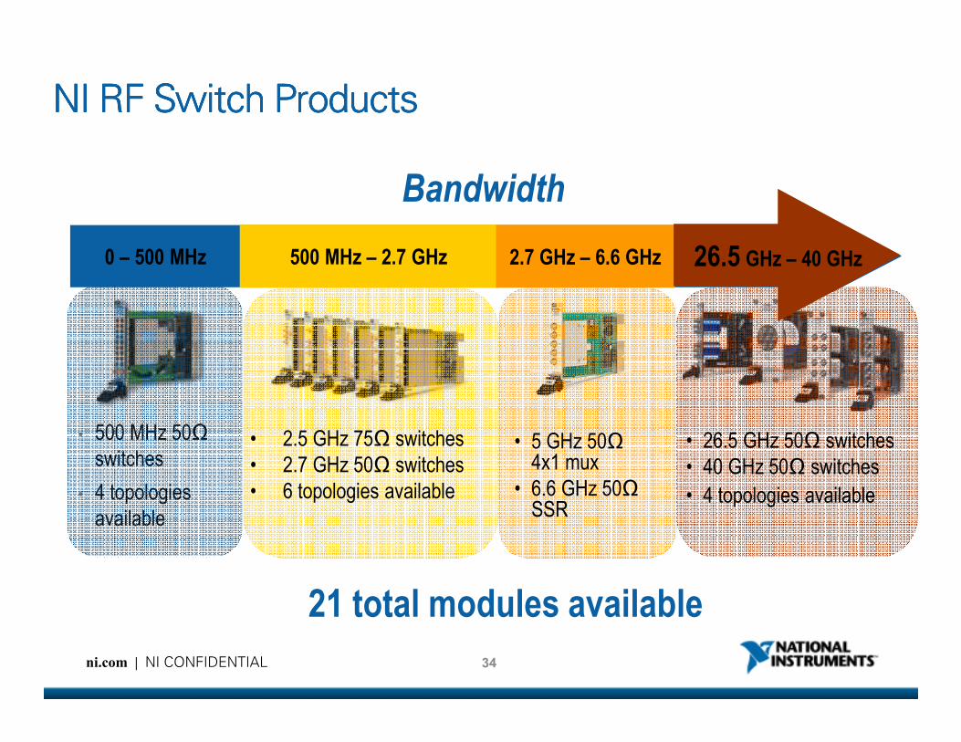
0 – 500 MHz
NI RF Switch ProductsNI RF Switch ProductsNI RF Switch ProductsNI RF Switch Products
Bandwidth
500 MHz – 2.7 GHz 2.7 GHz – 6.6 GHz 26.5 GHz – 40 GHz
34ni.com | NI CONFIDENTIAL
• 500 MHz 50
switches
• 4 topologies
available
• 2.5 GHz 75 switches
• 2.7 GHz 50 switches
• 6 topologies available
• 5 GHz 504x1 mux
• 6.6 GHz 50 SSR
• 26.5 GHz 50 switches
• 40 GHz 50 switches
• 4 topologies available
21 total modules available
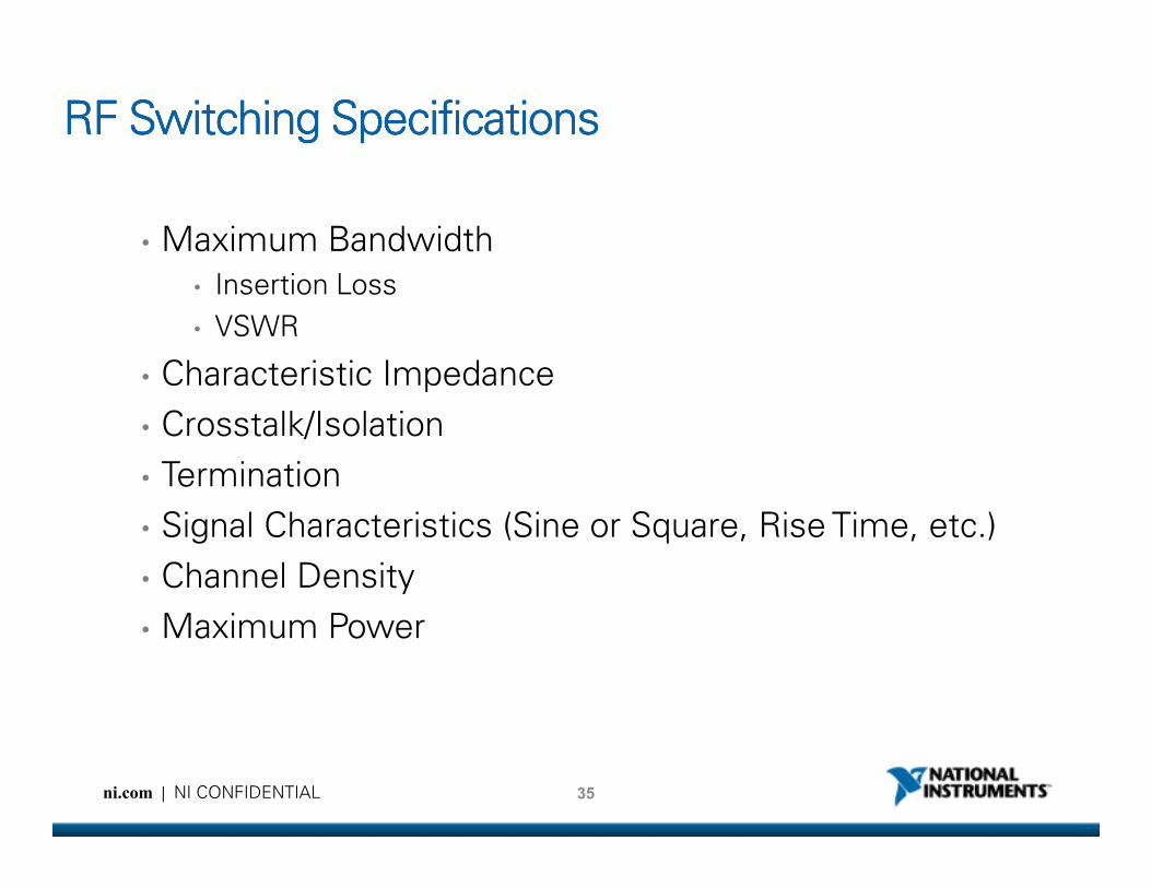
RF Switching SpecificationsRF Switching SpecificationsRF Switching SpecificationsRF Switching Specifications
• Maximum Bandwidth
• Insertion Loss
• VSWR
• Characteristic Impedance
• Crosstalk/Isolation
35ni.com | NI CONFIDENTIAL
• Termination
• Signal Characteristics (Sine or Square, Rise Time, etc.)
• Channel Density
• Maximum Power

What is Insertion Loss?What is Insertion Loss?What is Insertion Loss?What is Insertion Loss?
Zo=50ΩΩΩΩ
Pin Pout
50ΩΩΩΩ
Source Load
36ni.com | NI CONFIDENTIAL
50ΩΩΩΩ
Insertion Loss (dB) = 10 * log10 ( Pout / Pin )
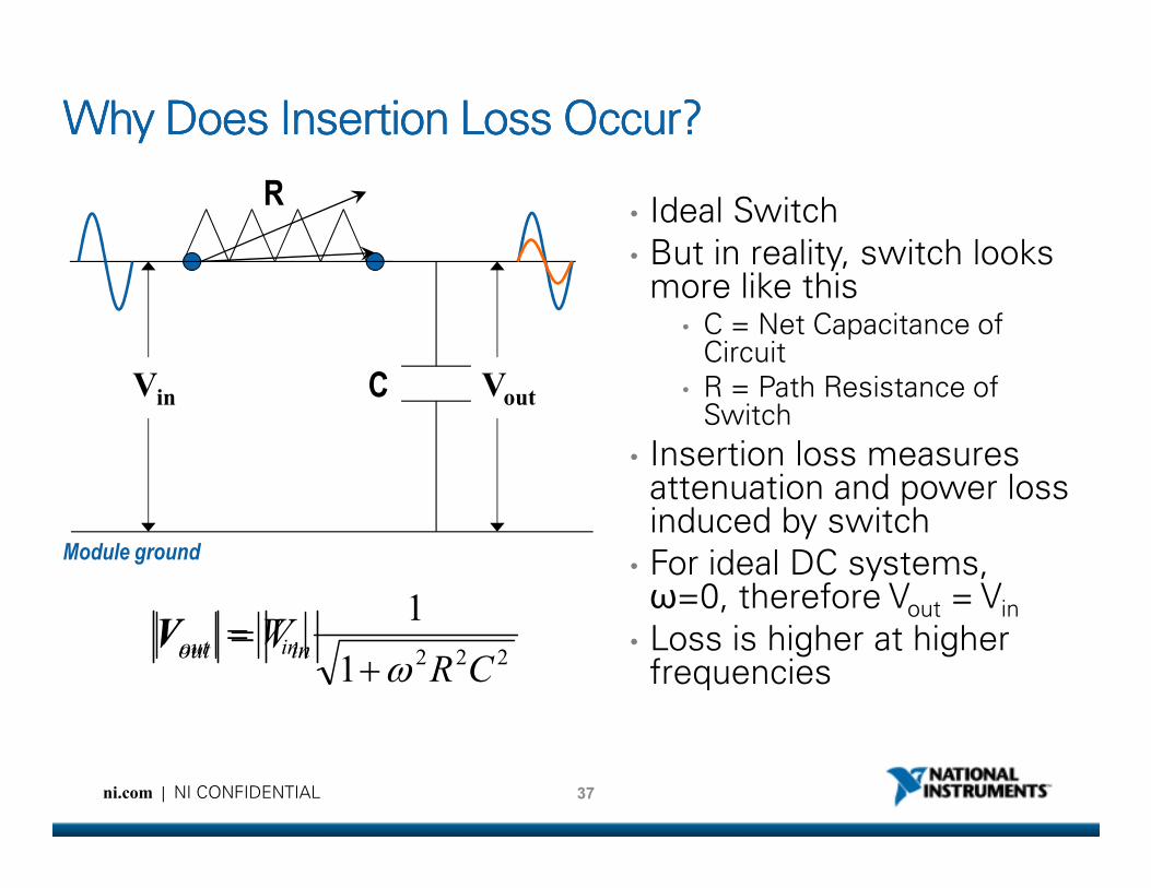
Why Does Insertion Loss Occur? Why Does Insertion Loss Occur? Why Does Insertion Loss Occur? Why Does Insertion Loss Occur?
• Ideal Switch
• But in reality, switch looks more like this
• C = Net Capacitance of Circuit
• R = Path Resistance of Switch
• Insertion loss measures
VoutVin
R
C
37ni.com | NI CONFIDENTIAL
2221
1
CRVV inout
ω+
=inout VV =
• Insertion loss measures attenuation and power loss induced by switch
• For ideal DC systems, ω=0, therefore Vout = Vin
• Loss is higher at higher frequencies
Module ground
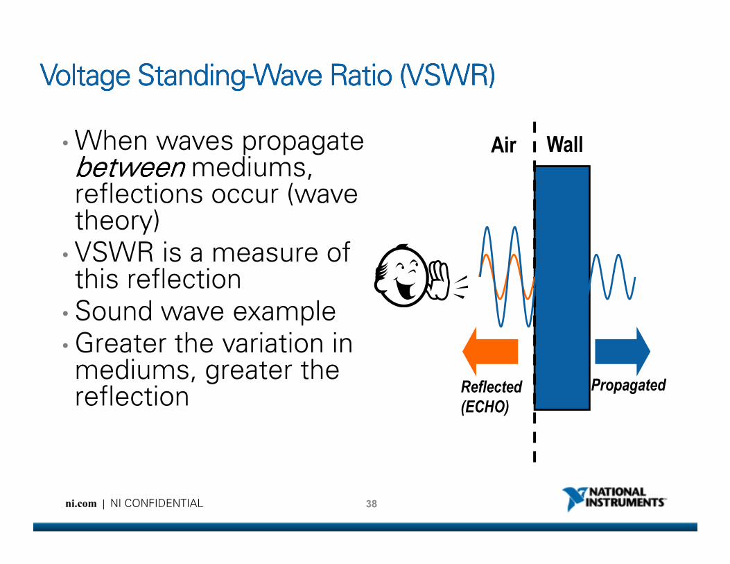
Voltage StandingVoltage StandingVoltage StandingVoltage Standing----Wave Ratio (VSWR)Wave Ratio (VSWR)Wave Ratio (VSWR)Wave Ratio (VSWR)
• When waves propagate betweenbetweenbetweenbetween mediums, reflections occur (wave theory)• VSWR is a measure of this reflection
Air Wall
38ni.com | NI CONFIDENTIAL
this reflection• Sound wave example• Greater the variation in mediums, greater the reflection
PropagatedReflected
(ECHO)
Facts About VSWRFacts About VSWRFacts About VSWRFacts About VSWR
• In electrical systems, reflections occur when signal
propagates through components with varying
characteristic impedances (connectors, relays, traces,
etc.)
• VSWR measures the power of this reflected signal
39ni.com | NI CONFIDENTIAL
• VSWR is an important consideration in systems
where signal reflections can damage the source

Characteristic Impedance Characteristic Impedance Characteristic Impedance Characteristic Impedance
• To minimize reflections, RF components are designed to have a certain per unit length impedance or ‘characteristic impedance’
• Characteristic impedance is not a DC resistance !!!
• Almost all RF systems have characteristic impedance of either 50 or 75 Ω
• To minimize reflections and maximize amount of power transferred from source to load transmitted, impedance of all components in RF system must be matched
40ni.com | NI CONFIDENTIAL
components in RF system must be matched
Zo≠ 50ΩΩΩΩ
Pin Pout
50ΩΩΩΩ
50ΩΩΩΩPreflected
Source Load
Matched 501 System (Ideal)
Pin = Pout and
Preflected = 0
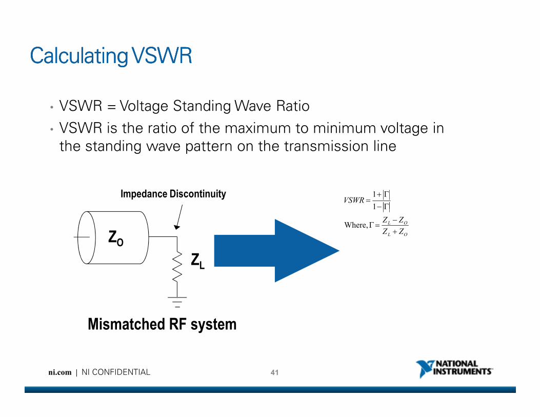
Calculating VSWRCalculating VSWRCalculating VSWRCalculating VSWR
• VSWR = Voltage Standing Wave Ratio
• VSWR is the ratio of the maximum to minimum voltage in
the standing wave pattern on the transmission line
VSWRΓ−
Γ+=1
1Impedance Discontinuity
41ni.com | NI CONFIDENTIAL
OL
OL
ZZ
ZZ
+
−=Γ
Γ−
Where,
1
ZL
ZO
Mismatched RF system
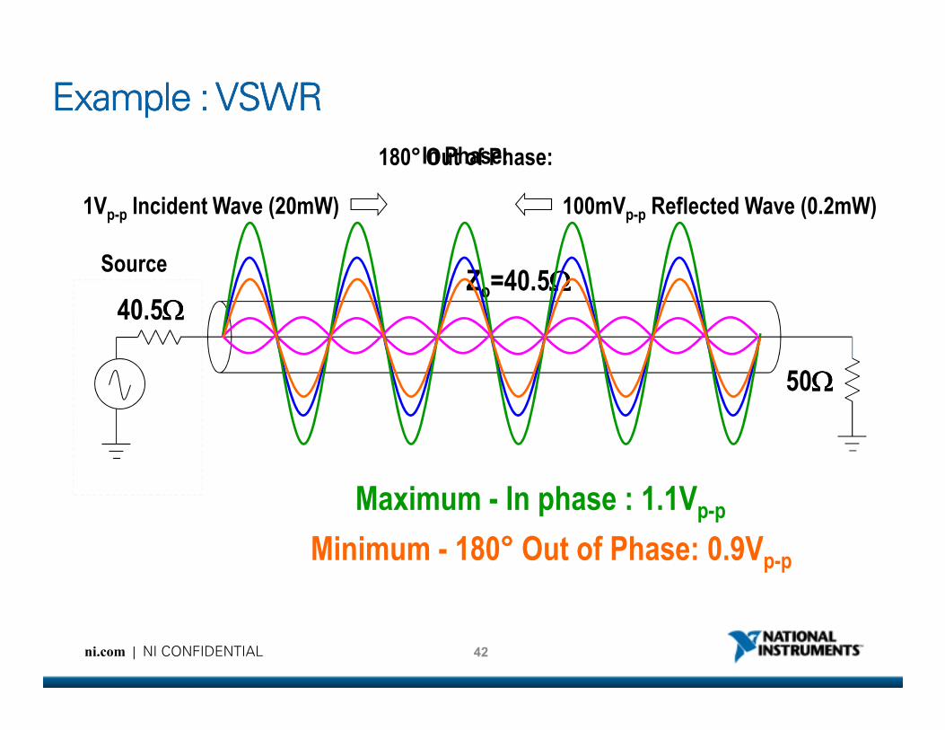
In Phase:180° Out of Phase:
Example : VSWRExample : VSWRExample : VSWRExample : VSWR
1Vp-p Incident Wave (20mW) 100mVp-p Reflected Wave (0.2mW)
40.5ΩΩΩΩ
SourceZo=40.5ΩΩΩΩ
50ΩΩΩΩ
42ni.com | NI CONFIDENTIAL
Maximum - In phase : 1.1Vp-p
Minimum - 180° Out of Phase: 0.9Vp-p
50ΩΩΩΩ
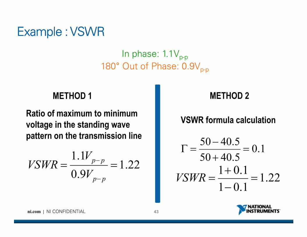
Example : VSWRExample : VSWRExample : VSWRExample : VSWR
In phase: 1.1Vp-p
180° Out of Phase: 0.9Vp-p
Ratio of maximum to minimum VSWR formula calculation
METHOD 1 METHOD 2
43ni.com | NI CONFIDENTIAL
1.05.4050
5.4050=
+
−=Γ
22.11.01
1.01=
−
+=VSWR
22.19.0
1.1==
−
−
pp
pp
V
VVSWR
voltage in the standing wave
pattern on the transmission line
VSWR formula calculation
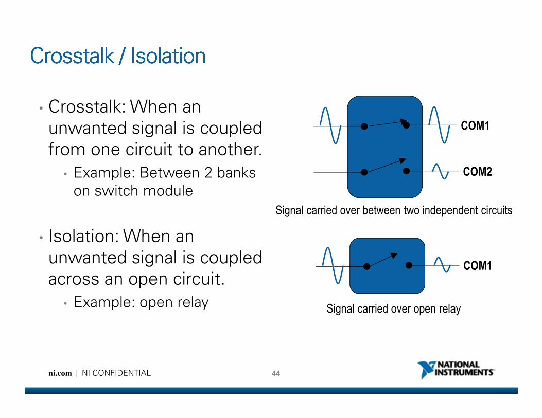
Crosstalk / IsolationCrosstalk / IsolationCrosstalk / IsolationCrosstalk / Isolation
• Crosstalk: When an
unwanted signal is coupled
from one circuit to another.
• Example: Between 2 banks
on switch module
COM1
COM2
Signal carried over between two independent circuits
44ni.com | NI CONFIDENTIAL
• Isolation: When an
unwanted signal is coupled
across an open circuit.
• Example: open relay
COM1
Signal carried over open relay
Signal carried over between two independent circuits
DUT 1 (501)
RFSA
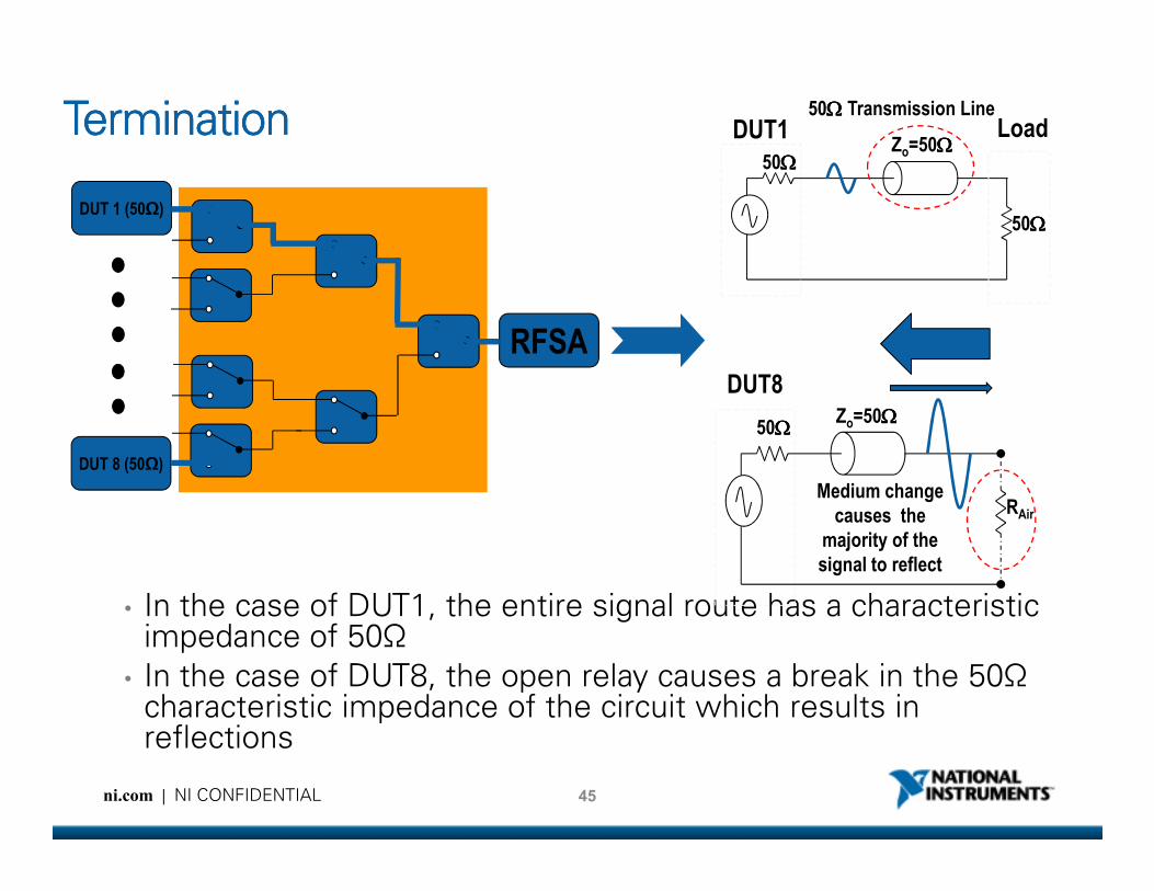
TerminationTerminationTerminationTermination 50Ω Ω Ω Ω Transmission Line
50ΩΩΩΩ
50ΩΩΩΩ
DUT1 LoadZo=50ΩΩΩΩ
50ΩΩΩΩ
DUT8Zo=50ΩΩΩΩ
45ni.com | NI CONFIDENTIAL
DUT 8 (501)
• In the case of DUT1, the entire signal route has a characteristic impedance of 50Ω
• In the case of DUT8, the open relay causes a break in the 50Ω characteristic impedance of the circuit which results in reflections
RAir
Medium change
causes the
majority of the
signal to reflect

Termination (cont)Termination (cont)Termination (cont)Termination (cont)
DUT 1 (501)
RFSA
50ΩΩΩΩ
50ΩΩΩΩ
DUT1 LoadZo=50ΩΩΩΩ
50Ω Ω Ω Ω Transmission Line
50ΩΩΩΩ
DUT4Zo=50ΩΩΩΩ
46ni.com | NI CONFIDENTIAL
• Termination is VERY crucial when the DUT is:• Continuously generating signal
• Sensitive to signal reflections
DUT 4 (501)
50ΩΩΩΩTermination
resistor keeps
reflections low
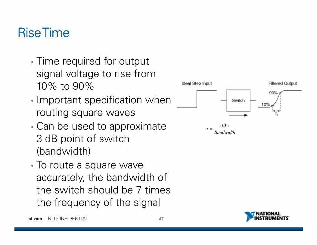
Rise TimeRise TimeRise TimeRise Time
• Time required for output
signal voltage to rise from
10% to 90%
• Important specification when
routing square waves
Can be used to approximate
47ni.com | NI CONFIDENTIAL
• Can be used to approximate
3 dB point of switch
(bandwidth)
• To route a square wave
accurately, the bandwidth of
the switch should be 7 times
the frequency of the signal
Bandwidth
35.0=τ
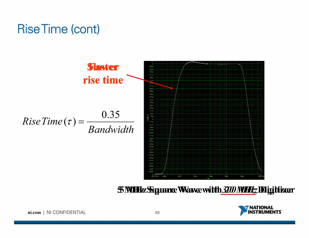
Rise Rise Rise Rise Time (cont)Time (cont)Time (cont)Time (cont)
TimeRise35.0
)( =τ
Slower
rise time
Faster
rise time
48ni.com | NI CONFIDENTIAL
BandwidthTimeRise
35.0)( =τ
5 MHz Square Wave with 20 MHz Digitizer5 MHz Square Wave with 300 MHz Digitizer
Considerations while using Switch Matrix
ni.com | NI CONFIDENTIAL

Switching LowSwitching LowSwitching LowSwitching Low----Voltage Signals (< 1 mV)Voltage Signals (< 1 mV)Voltage Signals (< 1 mV)Voltage Signals (< 1 mV)
• Thermal EMF
• Dissimilar metals create a voltage drop at their junction
• Typicalo Electromechanical: 1 - 10 uV
o Reed: 10-80 uV
• Creates a thermocouple that varies
JunctionJunctionJunctionJunction µV/µV/µV/µV/°°°°
CCCC
Copper-Copper <0.3
Copper-Gold 0.5
Copper-Silver 0.5
Copper-Brass 3
50ni.com | NI CONFIDENTIAL
• Creates a thermocouple that varies voltage offset with temperature
Copper-Brass 3
Copper-Nickel 0.5
Copper-Lead-Tin Solder 1-3
Copper-Aluminum 5
Copper-Kovar 40
Copper-Copper Oxide >500
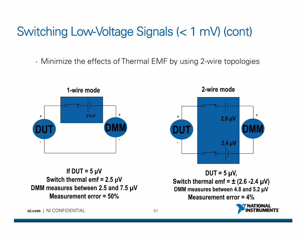
Switching LowSwitching LowSwitching LowSwitching Low----Voltage Signals (< 1 mV) (cont)Voltage Signals (< 1 mV) (cont)Voltage Signals (< 1 mV) (cont)Voltage Signals (< 1 mV) (cont)
• Minimize the effects of Thermal EMF by using 2-wire topologies
1-wire mode
2.5 µV+ +
2-wire mode
2.6 µV+ +
51ni.com | NI CONFIDENTIAL
DUT DMM
+
--
If DUT = 5 µV
Switch thermal emf = 2.5 µV
DMM measures between 2.5 and 7.5 µV
Measurement error = 50%
DUT DMM2.6 µV+
--
2.4 µV
DUT = 5 µV,
Switch thermal emf = ± (2.6 -2.4 µV)DMM measures between 4.8 and 5.2 µV
Measurement error = 4%
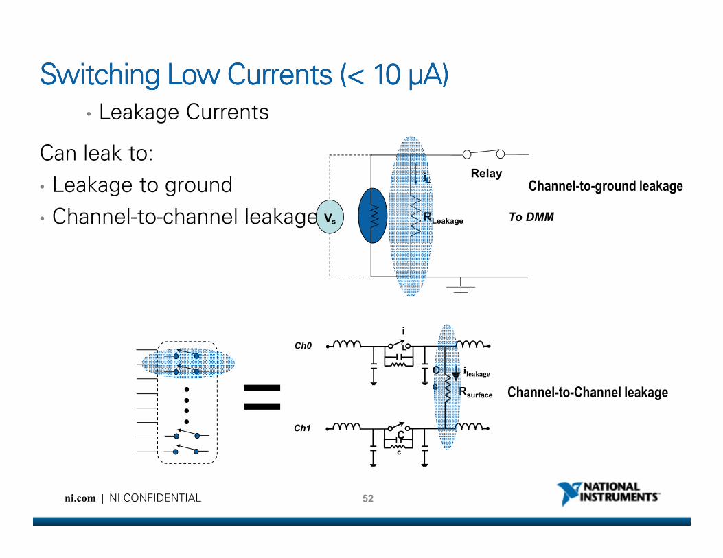
Switching Low Currents (< 10 Switching Low Currents (< 10 Switching Low Currents (< 10 Switching Low Currents (< 10 μμμμA)A)A)A)
• Leakage Currents
Can leak to:
• Leakage to ground
• Channel-to-channel leakage Vs RLeakage To DMM
iLRelay
Channel-to-ground leakage
52ni.com | NI CONFIDENTIAL
ileakage
C
c
C
G
i
L
Rsurface
Ch0
Ch1
Channel-to-Channel leakage
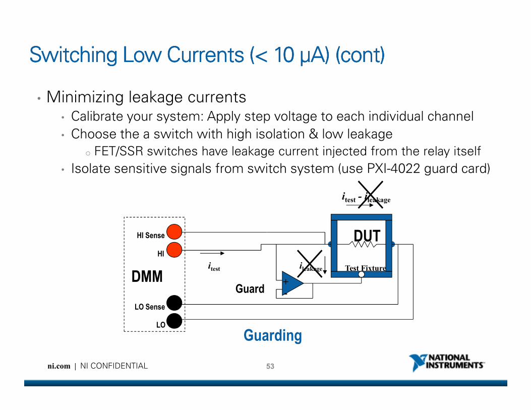
Switching Low Currents (< 10 Switching Low Currents (< 10 Switching Low Currents (< 10 Switching Low Currents (< 10 μμμμA) (cont)A) (cont)A) (cont)A) (cont)
• Minimizing leakage currents• Calibrate your system: Apply step voltage to each individual channel
• Choose the a switch with high isolation & low leakage
o FET/SSR switches have leakage current injected from the relay itself
• Isolate sensitive signals from switch system (use PXI-4022 guard card)
itest - ileakage
53ni.com | NI CONFIDENTIAL
DUTHI Sense
HI
LO Sense
LO
DMMitest ileakage
+
-Guard
Test Fixture
Guarding
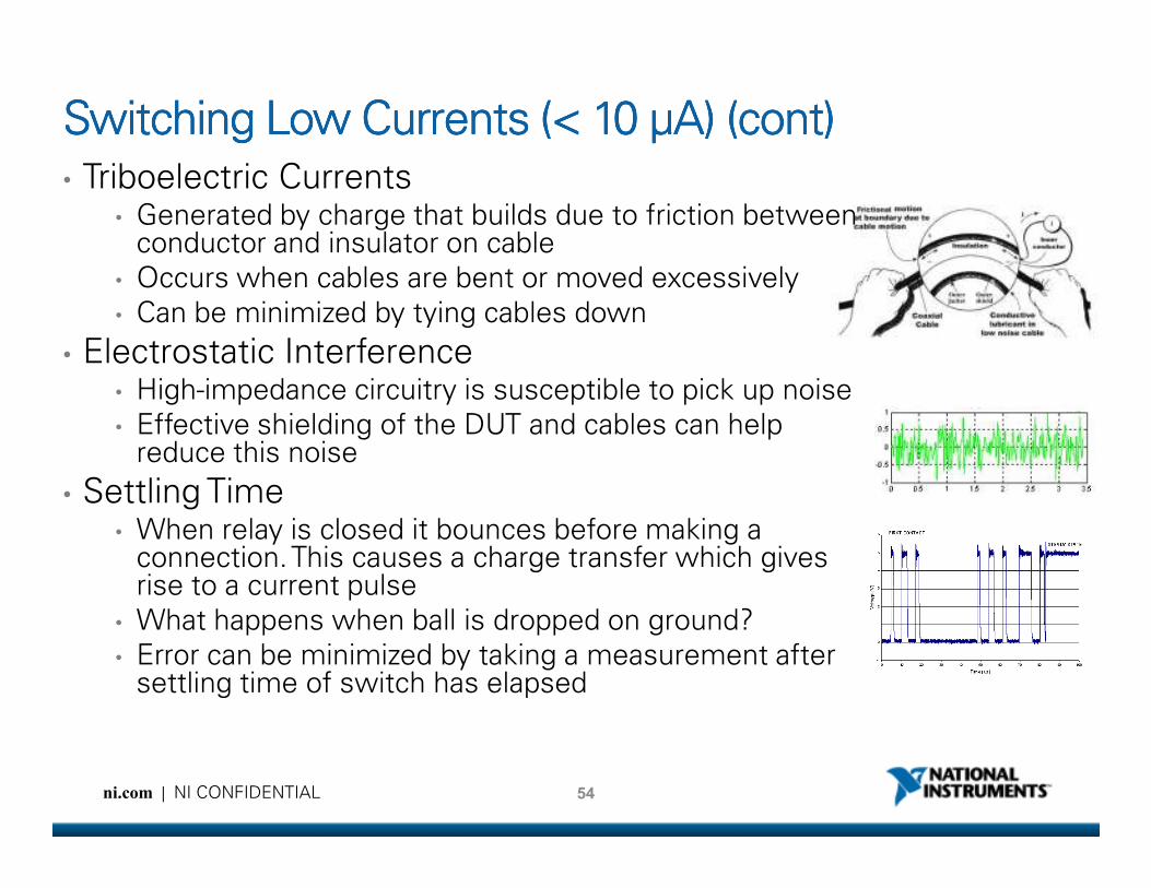
Switching Low Currents (< 10 Switching Low Currents (< 10 Switching Low Currents (< 10 Switching Low Currents (< 10 μμμμA) (cont)A) (cont)A) (cont)A) (cont)
• Triboelectric Currents• Generated by charge that builds due to friction between
conductor and insulator on cable
• Occurs when cables are bent or moved excessively
• Can be minimized by tying cables down
• Electrostatic Interference• High-impedance circuitry is susceptible to pick up noise
• Effective shielding of the DUT and cables can help reduce this noise
54ni.com | NI CONFIDENTIAL
reduce this noise
• Settling Time• When relay is closed it bounces before making a
connection. This causes a charge transfer which gives rise to a current pulse
• What happens when ball is dropped on ground?
• Error can be minimized by taking a measurement after settling time of switch has elapsed
Measuring Low Capacitance with SwitchesMeasuring Low Capacitance with SwitchesMeasuring Low Capacitance with SwitchesMeasuring Low Capacitance with Switches
• When performing Low Capacitance measurements, the
switch cannot add additional error.
• Selecting the right topology for these measurements
reduces added capacitance
• SPDT
• Matrix
55ni.com | NI CONFIDENTIAL
Matrix
• Select switches with:
• Low path resistance
• Low minimum current.
• Perform averaging on DMM.
• Perform Open / Short Compensation on DMM
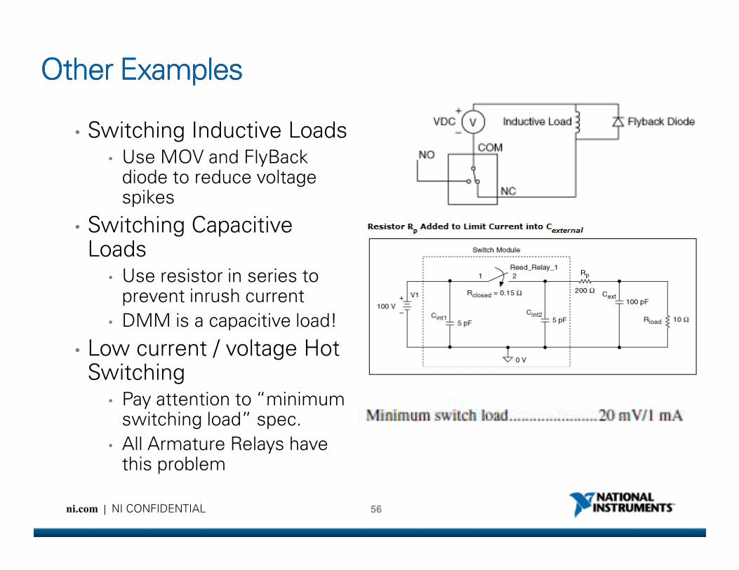
Other ExamplesOther ExamplesOther ExamplesOther Examples
• Switching Inductive Loads• Use MOV and FlyBack
diode to reduce voltage spikes
• Switching Capacitive Loads
• Use resistor in series to prevent inrush current
56ni.com | NI CONFIDENTIAL
Use resistor in series to prevent inrush current
• DMM is a capacitive load!
• Low current / voltage Hot Switching
• Pay attention to “minimum switching load” spec.
• All Armature Relays have this problem
NI Switch Executive
ni.com | NI CONFIDENTIAL
NI Switch Executive
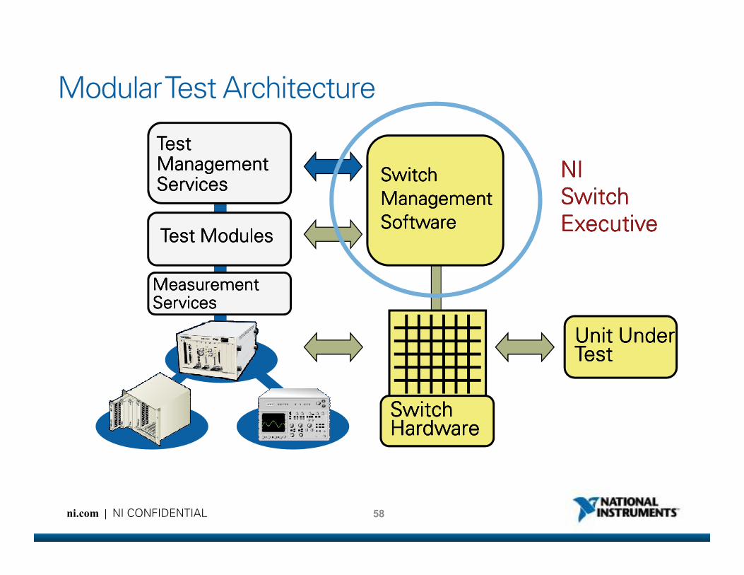
Modular Test Architecture
Test ModulesTest ModulesTest ModulesTest Modules
TestStandTestStandTestStandTestStand
TestTestTestTestManagementManagementManagementManagementServicesServicesServicesServices
Measurement Measurement Measurement Measurement
SwitchSwitchSwitchSwitch
ManagementManagementManagementManagement
SoftwareSoftwareSoftwareSoftware
NI NI NI NI
Switch Switch Switch Switch
ExecutiveExecutiveExecutiveExecutive
58ni.com | NI CONFIDENTIAL
Measurement Measurement Measurement Measurement ServicesServicesServicesServices
Unit UnderUnit UnderUnit UnderUnit UnderTestTestTestTest
SwitchSwitchSwitchSwitchHardwareHardwareHardwareHardware

Key Benefits to Switch Management SW
• Abstraction of low-level switch programming details• Reuse and easily maintain test modules
o Create test modules with generic switching calls (ex. connect “TestUUT1”)
o For new tests, reuse existing modules and create new NISE configuration
• Multimodule integration
59ni.com | NI CONFIDENTIAL
Multimodule integration• Create a virtual switch device integrating multiple switches
• NISE API treats virtual device as a single switch
• Automatic routing• Assists in creating routes across one or several switch
modules
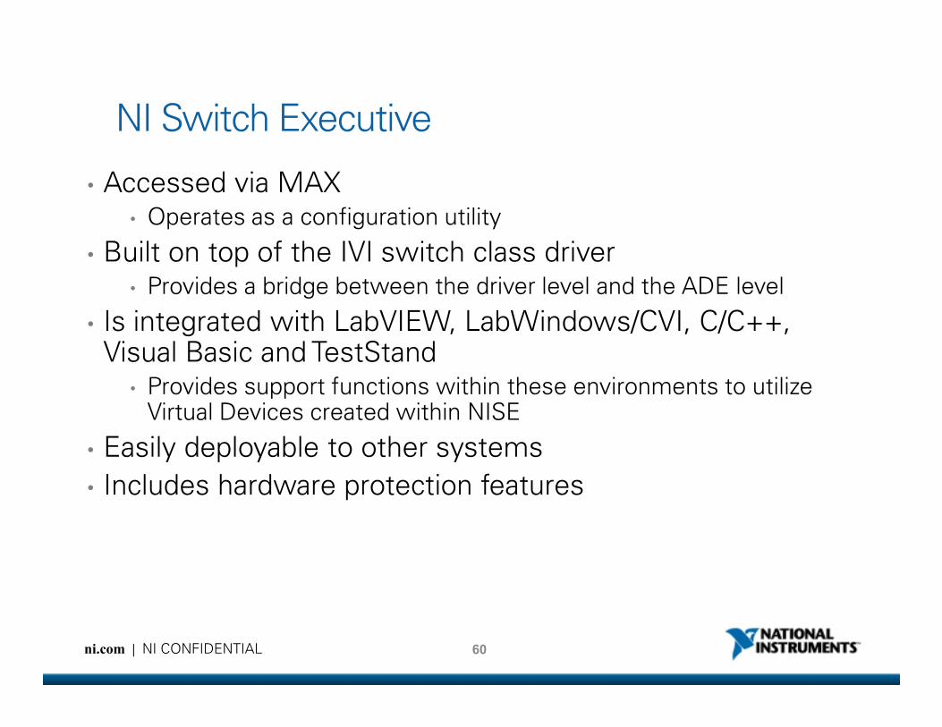
NI Switch Executive
• Accessed via MAX• Operates as a configuration utility
• Built on top of the IVI switch class driver• Provides a bridge between the driver level and the ADE level
• Is integrated with LabVIEW, LabWindows/CVI, C/C++, Visual Basic and TestStand
60ni.com | NI CONFIDENTIAL
Visual Basic and TestStand• Provides support functions within these environments to utilize
Virtual Devices created within NISE
• Easily deployable to other systems
• Includes hardware protection features

System Level Switch Management Software
• NI Switch Executive
− Visual Route Editor
− Supports common and custom topologies
Multi-module
61ni.com | NI CONFIDENTIAL
− Multi-module configuration
− End-to-end routing
− System validation
− Automated configuration export and system documentation
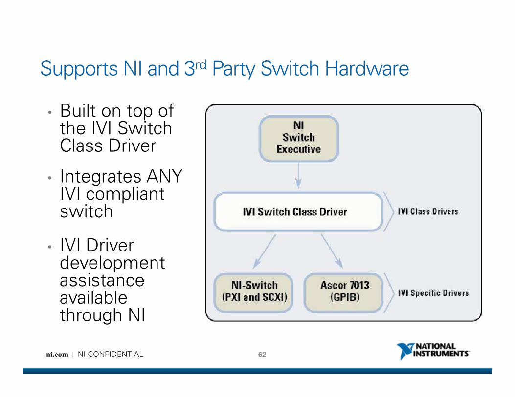
Supports NI and 3rd Party Switch Hardware
• Built on top of the IVI Switch Class Driver
• Integrates ANY IVI compliant
62ni.com | NI CONFIDENTIAL
IVI compliant switch
• IVI Driver development assistance available through NI
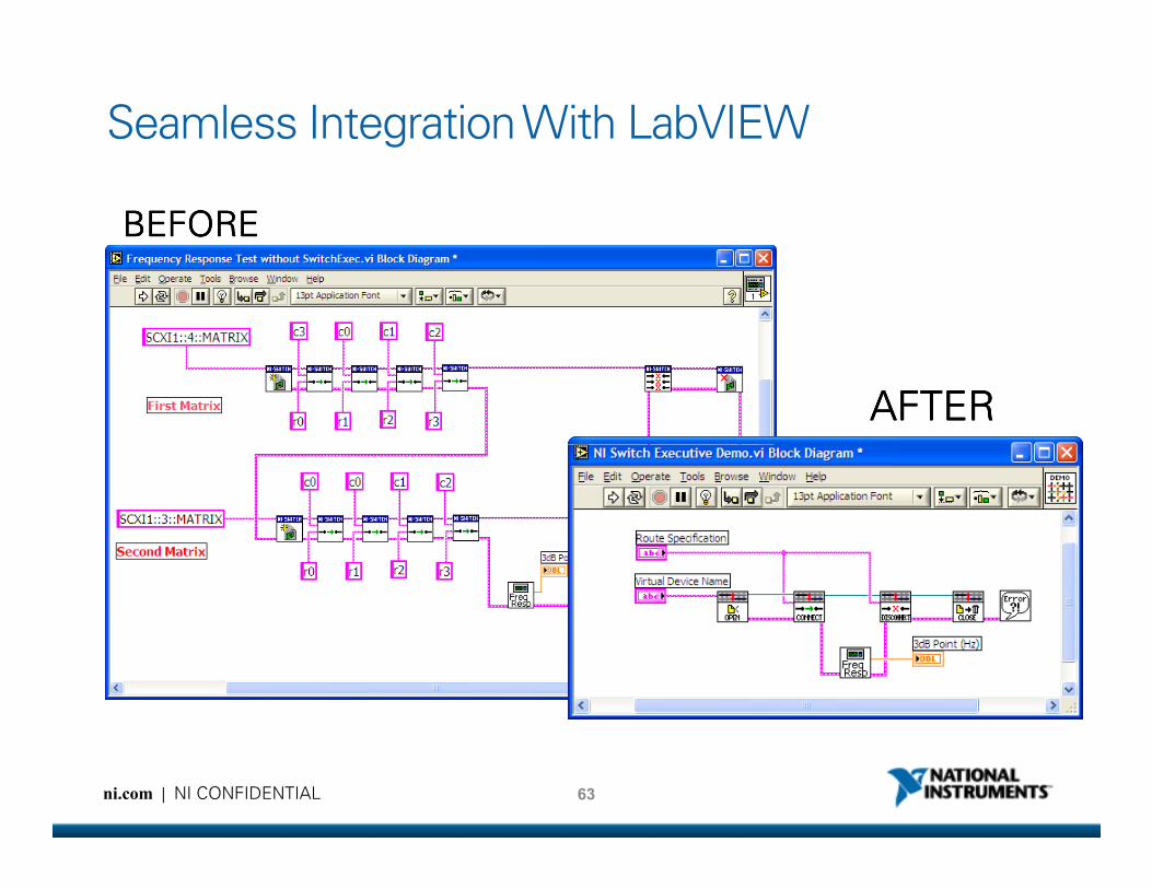
Seamless Integration With LabVIEW
BEFOREBEFOREBEFOREBEFORE
AFTERAFTERAFTERAFTER
63ni.com | NI CONFIDENTIAL
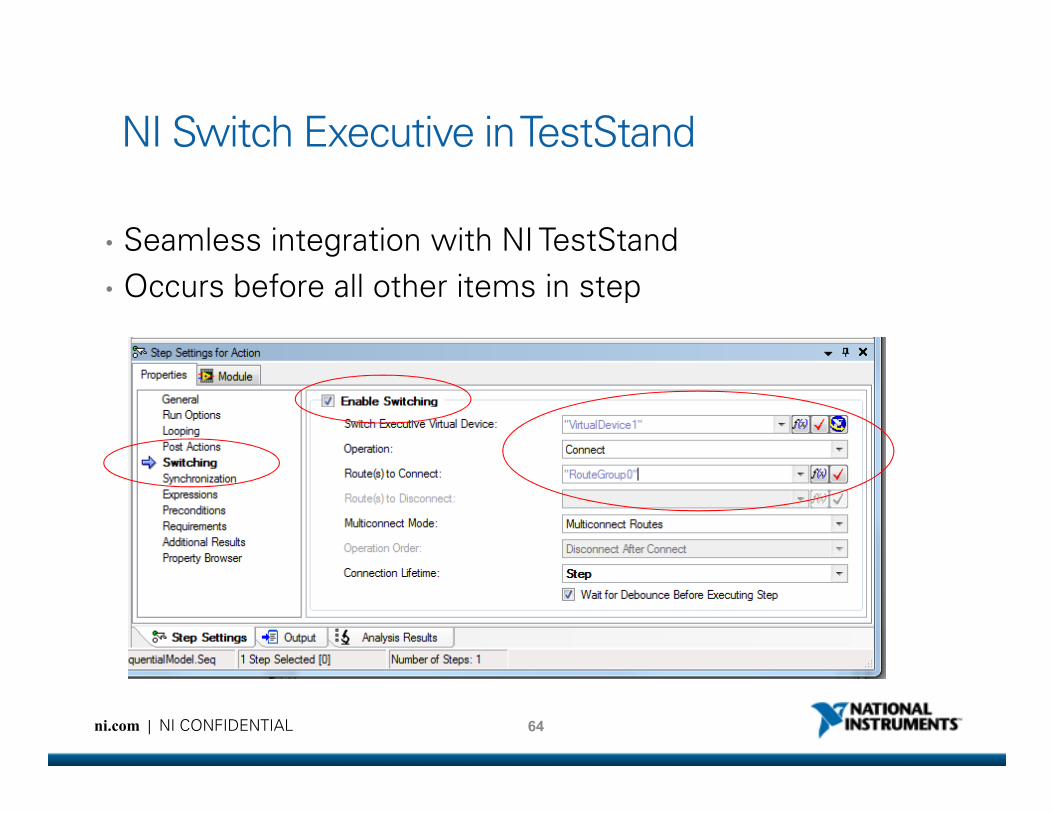
NI Switch Executive in TestStand
• Seamless integration with NI TestStand
• Occurs before all other items in step
64ni.com | NI CONFIDENTIAL
Summary
• Greatly simplify switch programming with switch management software• Multimodule integration
• Automatic routings
• Channel aliases, routes and route groups
• Abstract low-level programming for code reuse and maintenance
65ni.com | NI CONFIDENTIAL
• Abstract low-level programming for code reuse and maintenance
• Build scalable switch solutions with modular switch software• Open, modular switch platform
• Multiple topology devices
• System and module level switch software