Instrument Calibration
21
ENGINEERING GUIDE EG 15-14-1.2 Instrument Calibration Page 1 of 21 (This practice is appropriate for attachment to Inquiry or Purchase Document) Rev. 0 June 1999 ECA / EUSA Regional Engineering Guide ECA / EUSA SCOPE I 1.1 This guide covers calibration standards and recommended requirements for calibration procedures of pressure and temperature instruments. Frequency of calibration is recommended, but acceptable site practices will govern. I 1.2 Devices such as turbine meters, positive displacement meters, coriolis meters, capacitance level devices, etc. are not covered by this guide. I 1.3 The fundamental accuracy of flow elements, such as orifice plates, is not covered in this guide. SUMMARY OF ADDITIONAL REQUIREMENTS I 2.1 This guide is based on Exxon Research and Engineering Report EE.43E.85, “Instrumentation Calibration Guidelines,” by C. E. Gill. GENERAL R 3.1 The purpose of calibration procedures is to optimize the accuracy of devices that measure process variables (e.g., transmitters, transducers). Calibration procedures should be (1) simple and efficient, and (2) repeatable, regardless of time, location, and personnel. Calibration results are to be documented. R 3.2 Primary plant calibration standards are to be used to regularly check working standards and portable transfer standards, which in turn are used to check the operating instruments in the plant. DEFINITIONS I 4.1 Primary Plant Standards are measurement standards that are directly traceable to national or international standards and are maintained in a protected environment in the primary standards shop. Except for recertification, this primary plant standard should not leave the standards shop. I 4.2 Primary Standards Shop is a facility where primary calibration standards are maintained. This shop should be clean, dust-free, humidity-controlled, and maintained at a temperature of 72°F, ±4°F. I 4.3 Working Standard is a high-quality calibration standard which remains in the protected environment of the instrument shop. It should be directly compared with and proved against the primary plant standards. It should be used in the checking of portable transfer standards. I 4.4 Portable Transfer Standard is a portable calibration device intended for shop and field calibration of operational field transmitters and measurement equipment. These standards should have digital read-outs of 4-1/2 digits and an accuracy of at least two times better and resolution at least four times better than the field instruments on which they are used for calibration. I 4.5 Cardinal Calibration Points are defined as 0 percent, 50 percent, 75 percent, and 100 percent of the instrument range (except for square root extracting transmitters). I 4.6 Field Calibration is a calibration check and adjustment carried out with the transmitter or sensing device located in its permanent plant position. I 4.7 Bench Calibration is performed with the transmitter or sensing device removed from its permanent plant location and mounted in a controlled shop environment in an orientation identical to its field mounting configuration. I 4.8 Linearity is the difference between a straight-line transmitter output (or transducer response) at the cardinal points in the range and the actual output (response) during upscale excursion. I 4.9 Hysteresis is the difference between output measured at the cardinal points during an upscale excursion and the output measured at the cardinal points on the subsequent downscale return. I 4.10 Accuracy is the maximum deviation of the transmitter output (or transducer response) from the desired value during upscale or downscale excursion, whichever is greater. It is normally expressed as a percent of full scale, as determined at the cardinal points but may also be expressed in percent of reading or parts per million (ppm). The term “limits of uncertainty” is a synonym for accuracy. I 4.11 Optimum Calibrated Accuracy is the calibration which would give best accuracy in an instrument’s normal operating range. Generally, this will be in the mid 50 percent of its calibrated span. For differential pressure transmitters, Optimum Calibrated Accuracy should include final zero adjustments which may be required to compensate for high static line pressures.
-
Upload
kronikloops -
Category
Documents
-
view
155 -
download
5
description
For instrument tech
Transcript of Instrument Calibration

ENGINEERING GUIDE EG 15-14-1.2
Instrument Calibration Page 1 of 21
(This practice is appropriate for attachment to Inquiry or Purchase Document) Rev. 0 June 1999
ECA / EUSA Regional Engineering Guide
ECA / EUSA
SCOPEI 1.1 This guide covers calibration standards and recommended requirements for calibration procedures of
pressure and temperature instruments. Frequency of calibration is recommended, but acceptable sitepractices will govern.
I 1.2 Devices such as turbine meters, positive displacement meters, coriolis meters, capacitance level devices,etc. are not covered by this guide.
I 1.3 The fundamental accuracy of flow elements, such as orifice plates, is not covered in this guide.
SUMMARY OF ADDITIONAL REQUIREMENTSI 2.1 This guide is based on Exxon Research and Engineering Report EE.43E.85, “Instrumentation Calibration
Guidelines,” by C. E. Gill.
GENERALR 3.1 The purpose of calibration procedures is to optimize the accuracy of devices that measure process variables
(e.g., transmitters, transducers). Calibration procedures should be (1) simple and efficient, and (2)repeatable, regardless of time, location, and personnel. Calibration results are to be documented.
R 3.2 Primary plant calibration standards are to be used to regularly check working standards and portabletransfer standards, which in turn are used to check the operating instruments in the plant.
DEFINITIONSI 4.1 Primary Plant Standards are measurement standards that are directly traceable to national or international
standards and are maintained in a protected environment in the primary standards shop. Except forrecertification, this primary plant standard should not leave the standards shop.
I 4.2 Primary Standards Shop is a facility where primary calibration standards are maintained. This shop shouldbe clean, dust-free, humidity-controlled, and maintained at a temperature of 72°F, ±4°F.
I 4.3 Working Standard is a high-quality calibration standard which remains in the protected environment of theinstrument shop. It should be directly compared with and proved against the primary plant standards. Itshould be used in the checking of portable transfer standards.
I 4.4 Portable Transfer Standard is a portable calibration device intended for shop and field calibration ofoperational field transmitters and measurement equipment. These standards should have digital read-outsof 4-1/2 digits and an accuracy of at least two times better and resolution at least four times better than thefield instruments on which they are used for calibration.
I 4.5 Cardinal Calibration Points are defined as 0 percent, 50 percent, 75 percent, and 100 percent of theinstrument range (except for square root extracting transmitters).
I 4.6 Field Calibration is a calibration check and adjustment carried out with the transmitter or sensing devicelocated in its permanent plant position.
I 4.7 Bench Calibration is performed with the transmitter or sensing device removed from its permanent plantlocation and mounted in a controlled shop environment in an orientation identical to its field mountingconfiguration.
I 4.8 Linearity is the difference between a straight-line transmitter output (or transducer response) at the cardinalpoints in the range and the actual output (response) during upscale excursion.
I 4.9 Hysteresis is the difference between output measured at the cardinal points during an upscale excursionand the output measured at the cardinal points on the subsequent downscale return.
I 4.10 Accuracy is the maximum deviation of the transmitter output (or transducer response) from the desiredvalue during upscale or downscale excursion, whichever is greater. It is normally expressed as a percent offull scale, as determined at the cardinal points but may also be expressed in percent of reading or parts permillion (ppm). The term “limits of uncertainty” is a synonym for accuracy.
I 4.11 Optimum Calibrated Accuracy is the calibration which would give best accuracy in an instrument’s normaloperating range. Generally, this will be in the mid 50 percent of its calibrated span. For differential pressuretransmitters, Optimum Calibrated Accuracy should include final zero adjustments which may be requiredto compensate for high static line pressures.

EG 15-14-1.2 ENGINEERING GUIDE
Page 2 of 21 Instrument CalibrationRev. 0 June 1999 (This practice is appropriate for attachment to Inquiry or Purchase Document)
ECA / EUSA Regional Engineering Guide
ECA / EUSA
I 4.12 Traceability is the unbroken chain of comparison of measurement apparatus emanating from the Bureau ofInternational Physical Measurements (BIPM) in France through the various National Bureaus of Standardsthrough industrial metrology laboratories down to operational measurement equipment.
I 4.13 4½ Digit Meter is a digital indicator which is capable of displaying all ten digits (0 to 9) in the four leastsignificant places but can only display a limited number of digits in the most significant place. An example isa milliammeter which, on the 20 mA DC range, cannot digitize above 19.999 mA without loss of leastsignificant digit. The ½ digit refers to the “1” since in this place in the display, the only digits which willappear are either a blank or “1”.
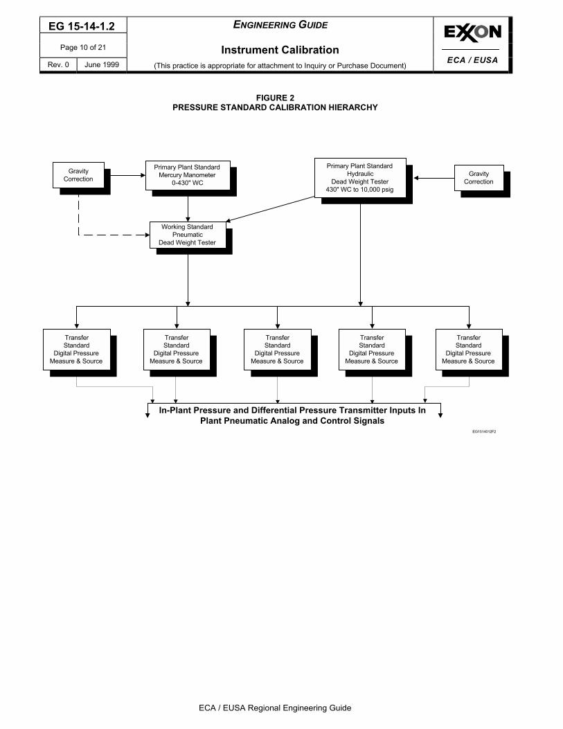
CALIBRATION HIERARCHYR 5.1 A hierarchy of primary plant standards should be maintained to compare against the working and transfer
standards used for normal calibration and checkout tasks. These primary plant standards shouldencompass the major variables measured within the plant including analog signals. Principal parametersare pressure, temperature, and electronic, (volts, ohms, and current):
ElectronicPressureTemperature
Figure 1Figure 2Figure 3
PRIMARY ELECTRONIC MEASUREMENT STANDARDSR 6.1 Each plant should maintain the following inventory of electrical standards which shall be kept in a locked
compartment when not in use.a. Primary Standard Voltage Cells – The primary standard for voltage should be an unsaturated
cadmium voltaic cell which produces a voltage of 1.0193 VDC ±0.0025 percent. Two unsaturatedcell units should be purchased as the primary plant voltage standards for the main calibration shopand be returned alternately each six months for recertification. Care must be employed in the use ofstandard cells. The principal rule which must be followed in their use is to avoid current loadsgreater than 0.1 MA by never connecting them to anything other than a high-impedance voltageinput device.
b. Primary Standard Resistances – The primary resistance standard should be NBS type resistorssuch as L&N Model Nos. 4020 B (1.0 ohm), 4025 B (10.0 ohms), and 4030 B (100 ohms) with anaccuracy of ±0.0001 percent.
R 6.2 The unsaturated voltaic cells should be used in conjunction with a Kelvin Varley divider (or ratio divider) todefine DC voltages ranging from microvolts to voltages of 0 to 100 and higher if necessary. The voltagesproduced by the Kelvin Varley divider should then be used to prove the plants working standard digitalmultimeter voltage scale. The procedure for proving the working standards should take approximately onehour and should be done once per week. This procedure should be carried out at a temperature of72° ± 4°F.
R 6.3 The working standard decade box should be checked against the working standard DVM at one-monthintervals. Before checking the decade box check the working standard DVM against the primary standardNBS resistors (values of 1.0, 10.0, and 100.0 ohms). The working standard DVM should agree with the NBSstandard resistors to an accuracy of ±0.01 percent of value. The working standard decade box should inturn agree with the working standard DVM to an accuracy of ±0.02 percent of value at the nominalresistances of 1.0, 10.0, and 100.0 ohms. Agreement between the working standard DVM and decaderesistance box should be ±0.04 percent of value, for ohmic value of 200 ohms to 1000 ohms.
R 6.4 After checking the Working Standard DVM, the Working Standard Voltage/current source should be checkedagainst the Working Standard DVM. Direct Voltage Checks should be made. Current output of thevoltage/current source should be checked by feeding its current output through a primary standardresistance and measuring the voltage drop with the Working Standard DVM. Tolerances should be ±0.02%of reading.

ENGINEERING GUIDE EG 15-14-1.2
Instrument Calibration Page 3 of 21
(This practice is appropriate for attachment to Inquiry or Purchase Document) Rev. 0 June 1999
ECA / EUSA Regional Engineering Guide
ECA / EUSA
PRIMARY PRESSURE MEASUREMENT STANDARDSR 7.1 The primary plant standard for pressures of 20 in. to 430 in. H2O should be a high quality mercury
manometer. Accuracy shall be ±0.02 percent of range or better. The manometer should be equipped with amagnified float index and vernier and compensation adjustments for ambient temperature and local value ofthe acceleration of gravity. The mercury should be replaced at least once every two years with fresh tripledistilled mercury. The principal purpose of this primary pressure standard is to prove pneumatic dead weighttesters at nominal values of 200 and 400 in. of water. Limits of error should be ±0.07 percent of range.Precision Bourdon tubes are considered as transfer standards.
E 7.2 Traps should be provided on both measurement ports of the manometer to prevent mercury spills. Each trapshould have a minimum capacity of 500 cc.
R 7.3 A safety valve, Circle Seal 500 Series or equal, should be installed on each trap to prevent over-pressure ofthe manometer. The safety valve should be set at 80% of the pressure rating of the manometer. In the caseof the Wallace and Tiernan FA-187, the pressure rating is 75 psig which requires a safety valve pressuresetting of 60 psig. Periodic bubble checks should be made on these safety valves to assure good seating.
R 7.4 The primary plant standard for pressures above 430 in. H2O should be a hydraulic dead weight tester(Ametek Type T or equal) with a manufacturer’s guaranteed accuracy of 0.03 percent of setting or better.The primary purpose of this instrument is to prove pneumatic dead weight testers over the range of 430 in.H2O to 1500 in. H2O and transfer standard portable pressure calibrators from 1500 in. H2O and higher.
R 7.5 Corrections for the ambient value of the acceleration of gravity shall be made for manometers and deadweight testers. Some values pertinent to Exxon operations are as follows:
SITEACCELERATION OFGRAVITY cm/sec2 SITE
ACCELERATION OFGRAVITY cm/sec2
Baltimore 980.088 67 LaBarge 979.707 80Baton Rouge 979.349 01 Unden 980.212 30Benicia 979.997 80 Maracaibo 978.159 72Billings 980.356 37 Marseille 980.473 55Edmonton 981.153 09 Montreal 980.630 09Fort Washington 980.171 00 Pittsburgh 980.097 70Genoa 980.543 44 Rio de Janeiro 978.789 90Hamburg 981.363 78 Sarnia 980.369 93Hong Kong 978.754 47 Singapore 978.066 68Houston (Baytown) 979.283 72 Southampton (UK) 981.115 50Ingolstadt 980.857 59 Valdez 981.993 49Karlsruhe 980.949 46 Vancouver 980.920 68
PRIMARY TEMPERATURE MEASUREMENT STANDARDSR 8.1 The primary plant standard for temperature calibration should be an appropriately selected set of fixed
temperature cells whose values conform to fixed points on the International Practical Temperature Scale(IPTS). Such cells are also known as “freeze point cells” and operate by obtaining a solid/liquid equilibriumof specific pure materials or elements at their melting point. In most refineries and chemical plants, a galliumcell and a tin cell of 29.7715°C and 231.9681°C respectively will serve the normally expected needs.
R 8.2 The two freeze point cells for gallium and tin serve as the primary temperatures against which the workingstandard platinum resistance thermometer should be checked. A variance of ±0.1°C between the freezepoint cells and the working standard is acceptable. This working standard resistance thermometer should bethe primary standard used for determining ambient temperature for calibration of thermocouple transmittersand portable transfer standards.
R 8.3 Since plant standard thermoelements are required, each plant should secure high-quality traceablethermoelements for each thermocouple or RTD type used within the plant. These should not leave theinstrument shop and should be kept in a locked compartment when not in use. These thermoelementsshould be sent back to the manufacturer on an annual basis for recertification.

EG 15-14-1.2 ENGINEERING GUIDE
Page 4 of 21 Instrument CalibrationRev. 0 June 1999 (This practice is appropriate for attachment to Inquiry or Purchase Document)
ECA / EUSA Regional Engineering Guide
ECA / EUSA
R 8.4 For fast checking of operational thermoelements, an isothermal block may be employed which can easily bemade in the plant (see Figure 4). Into one end is inserted the plant standard thermoelement and into theother is inserted the thermoelement under test. The block can be heated or cooled to any arbitrarytemperature and then have the insulation slipped over it, the end cap insulation installed and thethermoelements inserted and their output measured for comparison purposes.
CALIBRATION FREQUENCYR 9.1 Frequency of calibration of field devices is related to equipment, application, and experience. Calibration
checks and time intervals are dictated by one or more of the following criteria:a. If the periodic zero check dictates readjustment of the zero, a complete recalibration should be
scheduled.b. Substantive evidence is provided by operations which indicates that the transmitter’s output is
suspect.c. Contractual obligations call for more frequent complete calibration checks.d. Accurate record keeping via calibration reports indicate that calibration intervals may be extended or
must shortened.
BASIC CALIBRATION RULESR 10.1 Interconnection of electronic components including primary plant standards and working standards shall be
made with gold-plated spade lugs which are soldered to their leads. Leads will be standard #14 AWG,minimum. Alligator clip leads and banana plugs should be avoided.
FIELD-MOUNTED INSTRUMENTS
R 10.2 All instrument components should be calibrated as separate stand-alone devices. System calibrations wheremultiple components sequentially receive and transmit or modify a signal should be avoided.
I 10.3 During calibration of pressure, differential pressure and pneumatic instruments, temporary connectionsshould preferably be made using plastic or brass compression fittings. The purpose for this is:a. For ease of making up connections without leaks.b. To avoid damage to the instruments’ threaded connections during calibration (e.g., galling of
stainless steel threads).R 10.4 All transfer standards used in calibration of field equipment should have digital readouts (4½ digits
minimum).R 10.5 Unless overriding considerations exist, zero adjustment should take place at 25 percent of range (rising) and
span adjustment shall take place at 75 percent of range (rising). One exception is square-root extractingdifferential pressure flow transmitters where the zero adjustment should take place at 10 percent of ∆Prange and span adjustment should take place at 75 percent of ∆P range. (NOTE: Zero adjustment refers tothe process of making the transmitter output at 25% of range agree with a known value, or at 10% forsquare-root extracting transmitters.)
R 10.6 Transmitter calibrations should be made only at ambient temperatures between 40°F and 90°F. Calibrationsmade outside these limits should be considered temporary and a recalibration performed when conditionspermit.
R 10.7 Permanent calibrations for transmitters in custody transfer, energy and/or material balance services shouldbe made on the bench in the instrument shop.
R 10.8 Where calibrations are carried out by contractor, the contractor should have his own primary plant standardsand should follow the procedures defined in this standard. If the contractor does not have primary plantstandards, his portable transfer standards should be checked against the plant’s primary standards using theprocedures in this standard.
ENGINEERING GUIDE EG 15-14-1.2
Instrument Calibration Page 5 of 21
(This practice is appropriate for attachment to Inquiry or Purchase Document) Rev. 0 June 1999
ECA / EUSA Regional Engineering Guide
ECA / EUSA
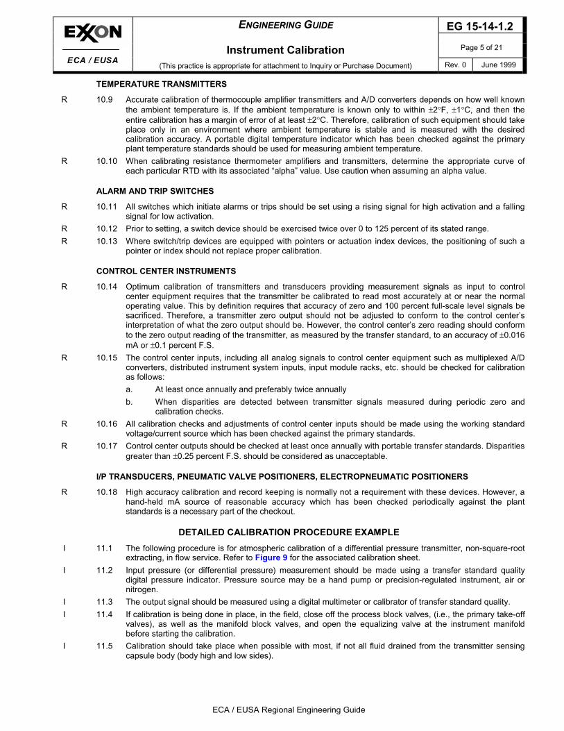
TEMPERATURE TRANSMITTERS
R 10.9 Accurate calibration of thermocouple amplifier transmitters and A/D converters depends on how well knownthe ambient temperature is. If the ambient temperature is known only to within ±2°F, ±1°C, and then theentire calibration has a margin of error of at least ±2°C. Therefore, calibration of such equipment should takeplace only in an environment where ambient temperature is stable and is measured with the desiredcalibration accuracy. A portable digital temperature indicator which has been checked against the primaryplant temperature standards should be used for measuring ambient temperature.
R 10.10 When calibrating resistance thermometer amplifiers and transmitters, determine the appropriate curve ofeach particular RTD with its associated “alpha” value. Use caution when assuming an alpha value.
ALARM AND TRIP SWITCHES
R 10.11 All switches which initiate alarms or trips should be set using a rising signal for high activation and a fallingsignal for low activation.
R 10.12 Prior to setting, a switch device should be exercised twice over 0 to 125 percent of its stated range.R 10.13 Where switch/trip devices are equipped with pointers or actuation index devices, the positioning of such a
pointer or index should not replace proper calibration.
CONTROL CENTER INSTRUMENTS
R 10.14 Optimum calibration of transmitters and transducers providing measurement signals as input to controlcenter equipment requires that the transmitter be calibrated to read most accurately at or near the normaloperating value. This by definition requires that accuracy of zero and 100 percent full-scale level signals besacrificed. Therefore, a transmitter zero output should not be adjusted to conform to the control center’sinterpretation of what the zero output should be. However, the control center’s zero reading should conformto the zero output reading of the transmitter, as measured by the transfer standard, to an accuracy of ±0.016mA or ±0.1 percent F.S.
R 10.15 The control center inputs, including all analog signals to control center equipment such as multiplexed A/Dconverters, distributed instrument system inputs, input module racks, etc. should be checked for calibrationas follows:a. At least once annually and preferably twice annuallyb. When disparities are detected between transmitter signals measured during periodic zero and
calibration checks.R 10.16 All calibration checks and adjustments of control center inputs should be made using the working standard
voltage/current source which has been checked against the primary standards.R 10.17 Control center outputs should be checked at least once annually with portable transfer standards. Disparities
greater than ±0.25 percent F.S. should be considered as unacceptable.
I/P TRANSDUCERS, PNEUMATIC VALVE POSITIONERS, ELECTROPNEUMATIC POSITIONERS
R 10.18 High accuracy calibration and record keeping is normally not a requirement with these devices. However, ahand-held mA source of reasonable accuracy which has been checked periodically against the plantstandards is a necessary part of the checkout.
DETAILED CALIBRATION PROCEDURE EXAMPLEI 11.1 The following procedure is for atmospheric calibration of a differential pressure transmitter, non-square-root
extracting, in flow service. Refer to Figure 9 for the associated calibration sheet.I 11.2 Input pressure (or differential pressure) measurement should be made using a transfer standard quality
digital pressure indicator. Pressure source may be a hand pump or precision-regulated instrument, air ornitrogen.
I 11.3 The output signal should be measured using a digital multimeter or calibrator of transfer standard quality.I 11.4 If calibration is being done in place, in the field, close off the process block valves, (i.e., the primary take-off
valves), as well as the manifold block valves, and open the equalizing valve at the instrument manifoldbefore starting the calibration.
I 11.5 Calibration should take place when possible with most, if not all fluid drained from the transmitter sensingcapsule body (body high and low sides).
EG 15-14-1.2 ENGINEERING GUIDE
Page 6 of 21 Instrument CalibrationRev. 0 June 1999 (This practice is appropriate for attachment to Inquiry or Purchase Document)
ECA / EUSA Regional Engineering Guide
ECA / EUSA
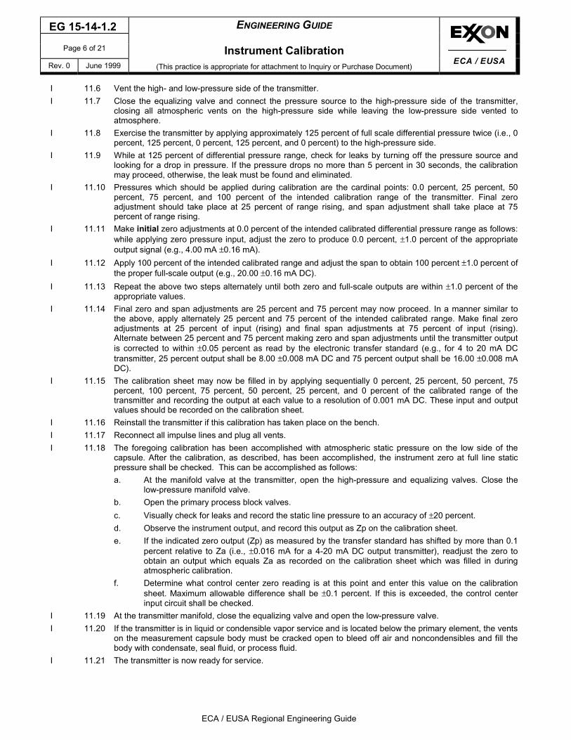
I 11.6 Vent the high- and low-pressure side of the transmitter.I 11.7 Close the equalizing valve and connect the pressure source to the high-pressure side of the transmitter,
closing all atmospheric vents on the high-pressure side while leaving the low-pressure side vented toatmosphere.
I 11.8 Exercise the transmitter by applying approximately 125 percent of full scale differential pressure twice (i.e., 0percent, 125 percent, 0 percent, 125 percent, and 0 percent) to the high-pressure side.
I 11.9 While at 125 percent of differential pressure range, check for leaks by turning off the pressure source andlooking for a drop in pressure. If the pressure drops no more than 5 percent in 30 seconds, the calibrationmay proceed, otherwise, the leak must be found and eliminated.
I 11.10 Pressures which should be applied during calibration are the cardinal points: 0.0 percent, 25 percent, 50percent, 75 percent, and 100 percent of the intended calibration range of the transmitter. Final zeroadjustment should take place at 25 percent of range rising, and span adjustment shall take place at 75percent of range rising.
I 11.11 Make initial zero adjustments at 0.0 percent of the intended calibrated differential pressure range as follows:while applying zero pressure input, adjust the zero to produce 0.0 percent, ±1.0 percent of the appropriateoutput signal (e.g., 4.00 mA ±0.16 mA).
I 11.12 Apply 100 percent of the intended calibrated range and adjust the span to obtain 100 percent ±1.0 percent ofthe proper full-scale output (e.g., 20.00 ±0.16 mA DC).
I 11.13 Repeat the above two steps alternately until both zero and full-scale outputs are within ±1.0 percent of theappropriate values.
I 11.14 Final zero and span adjustments are 25 percent and 75 percent may now proceed. In a manner similar tothe above, apply alternately 25 percent and 75 percent of the intended calibrated range. Make final zeroadjustments at 25 percent of input (rising) and final span adjustments at 75 percent of input (rising).Alternate between 25 percent and 75 percent making zero and span adjustments until the transmitter outputis corrected to within ±0.05 percent as read by the electronic transfer standard (e.g., for 4 to 20 mA DCtransmitter, 25 percent output shall be 8.00 ±0.008 mA DC and 75 percent output shall be 16.00 ±0.008 mADC).
I 11.15 The calibration sheet may now be filled in by applying sequentially 0 percent, 25 percent, 50 percent, 75percent, 100 percent, 75 percent, 50 percent, 25 percent, and 0 percent of the calibrated range of thetransmitter and recording the output at each value to a resolution of 0.001 mA DC. These input and outputvalues should be recorded on the calibration sheet.
I 11.16 Reinstall the transmitter if this calibration has taken place on the bench.I 11.17 Reconnect all impulse lines and plug all vents.I 11.18 The foregoing calibration has been accomplished with atmospheric static pressure on the low side of the
capsule. After the calibration, as described, has been accomplished, the instrument zero at full line staticpressure shall be checked. This can be accomplished as follows:a. At the manifold valve at the transmitter, open the high-pressure and equalizing valves. Close the
low-pressure manifold valve.b. Open the primary process block valves.c. Visually check for leaks and record the static line pressure to an accuracy of ±20 percent.d. Observe the instrument output, and record this output as Zp on the calibration sheet.e. If the indicated zero output (Zp) as measured by the transfer standard has shifted by more than 0.1
percent relative to Za (i.e., ±0.016 mA for a 4-20 mA DC output transmitter), readjust the zero toobtain an output which equals Za as recorded on the calibration sheet which was filled in duringatmospheric calibration.
f. Determine what control center zero reading is at this point and enter this value on the calibrationsheet. Maximum allowable difference shall be ±0.1 percent. If this is exceeded, the control centerinput circuit shall be checked.
I 11.19 At the transmitter manifold, close the equalizing valve and open the low-pressure valve.I 11.20 If the transmitter is in liquid or condensible vapor service and is located below the primary element, the vents
on the measurement capsule body must be cracked open to bleed off air and noncondensibles and fill thebody with condensate, seal fluid, or process fluid.
I 11.21 The transmitter is now ready for service.

ENGINEERING GUIDE EG 15-14-1.2
Instrument Calibration Page 7 of 21
(This practice is appropriate for attachment to Inquiry or Purchase Document) Rev. 0 June 1999
ECA / EUSA Regional Engineering Guide
ECA / EUSA
I 11.22 Calibration procedures for square root-extracting ∆P flow transmitters are the same as for non-square-rootextracting transmitters except the cardinal points are 0 percent, 10 percent, 25 percent, 50 percent, and 100percent of differential pressure range. Proper outputs for these points are as follows:
DIFFERENTIAL PRES. % OUTPUT %mA DC VALUE FOR
4-20 mA TRANSMITTER0 0 4.000
10 31.63 9.06125 50.00 12.00050 70.71 15.314100 100.00 20.000
Basic calibration adjustments of zero and span should be made at 10 percent and 100 percent of thedifferential pressure range. However, final full line pressure zero adjustment has a greater tolerance thanwith non-square-root extracting and should be 1.0 percent of output (e.g., 0.16 mA DC for a 4-20 mAtransmitter). This same tolerance applies when periodic zero checks are made.Note: For Configurable transmitters such as the Honeywell ST-3000, periodic zero checks should be made by
temporarily reconfiguring the transmitter to “linear” in which case the criteria for non-square-root extractingapplies.
PERIODIC ZERO CHECKSR 12.1 Repetitive or substantial zero shifts are a reasonable basis for scheduling a complete recalibration of a
transmitter since:a. Zero shifts associated with modern ∆P transmitters due to static line pressure effects are generally
small and repeatable.b. Zero shifts of modern transmitters due to other effects are much smaller than zero shifts of older
vintage transmitters.c. Substantial zero shifts are a good indication of a faulty transmitter.
R 12.2 The following paragraphs contain the procedure for performing periodic zero check on differential pressuretransmitters.a. Using a transfer standard, read the transmitter output and refer to the calibration report for the last
full calibration performed on the transmitter. Check that the operating full line pressure is within 20percent of value used for the last full calibration.
b. At the transmitter, close off the manifold valve on the low pressure side of the measuring capsuleand open the equalizing valve, thus placing full equal line pressure on both sides of the transmitter.
c. The transmitter output should read Za 0.1 percent (i.e., Za 0.016 mA DC). If this is the case, nofurther action need be taken. Proceed to paragraphs f and g.
d. If the zero output is outside of these limits, the technician should again check to determine that thestatic line pressure is within 20 percent of the static line pressure used for the last full calibration. Ifthe line pressure is within 20 percent, the transmitter should be replaced.
e. If the static line pressure is more than 20 percent different than that used for the last completecalibration, shut off all block valves and using the vent plugs in the transmitter body vent both highand low sides to atmosphere. Refer to the calibration sheet for the value Zp and Za. The transmittershould now produce an output equal to [(2 x Za) Zp] 0.016 mA. If so, no further adjustments arerequired. If the indicated zero output shows a deviation greater than 0.016 mA, readjust the zero toequal (2 x Za) Zp. The transmitter is faulty and should be repaired or replaced.
f. After zero check in Paragraph c, or rezeroing in Paragraphs d and e, determine what the controlcenter zero reading is and enter this value on the calibration sheet.
g. Plug all vents and close the equalizing valve and open the high and low pressure shut-off valves atthe transmitter manifold.
h. The transmitter is now back in service (on a temporary basis pending complete recalibration if thecriteria for Za given in Paragraph c has not been met).

EG 15-14-1.2 ENGINEERING GUIDE
Page 8 of 21 Instrument CalibrationRev. 0 June 1999 (This practice is appropriate for attachment to Inquiry or Purchase Document)
ECA / EUSA Regional Engineering Guide
ECA / EUSA
SPECIAL CALIBRATION PROCEDURES FOR HIGHEST ACCURACY TRANSMITTERSR 13.1 For energy and custody transfer flow meters and tank level inventory transmitters or sensors, it is possible to
achieve calibrations of pressure and differential pressure to an accuracy of 0.05 percent of full scale orbetter. Calibration of this type shall take place on the bench in the instrument shop and will require specialequipment, namely an extremely high accuracy dead weight tester with dual outputs (for ∆P calibrations).(NOTE: Most instrument shops will not have this very expensive piece of test equipment.)
CALIBRATION REPORTSI 14.1 A documentation system should be utilized which generates calibration records for the following categories:
a. Transmitters.b. Switches.c. Critical temperature elements.d. Calibration of control center devices.e. Calibration checks of portable standards against the primary and working standards.
I 14.2 Instrument calibration sheets should be filled out for all formal calibrations and recalibrations performed byplant or contractor personnel.
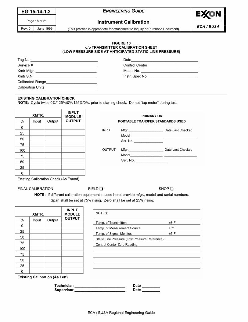
I 14.3 Following figures can be used for calibration documentation:Pressure - Portable Transfer Standard CheckElectrical Portable Transfer Standard CheckTemperature Portable Transfer Standard CheckBasic Transmitter Calibration SheetD/P Transmitter Calibration Sheet (Low Pressure Side at Atmosphere)D/P Transmitter Calibration Sheet (Low Pressure Side at Line Pressure)Alarm, Switching, and Trip Instrument Calibration SheetCritical Temperature Element Calibration CheckCalibration Sheet for Control Center Instruments
Figure 5Figure 6Figure 7Figure 8Figure 9
Figure 10Figure 11Figure 12Figure 13
Revision Memo6/99 Revision 0 - Original Issue of Engineering Guide

ENGINEERING GUIDE EG 15-14-1.2
Instrument Calibration Page 9 of 21
(This practice is appropriate for attachment to Inquiry or Purchase Document) Rev. 0 June 1999
ECA / EUSA Regional Engineering Guide
ECA / EUSA
FIGURE 1ELECTRONIC STANDARDS CALIBRATION HIERARCHY
Primary Plant StandardResistance
1.0, 10.0 & 100.0 Ohm
Primary Plant StandardUnsaturated Voltaic Cell
Null Detectorand Kelvin Varley Divider
Working StandardMillamp & Voltage
Source
Working StandardDigital Multimeter
Working StandardDecade Box
pHCalibrators
Portable DigitalTransfer StandardMV, V, MA, Ohms
PortableThermocoupleTemperatureMeasurement
&Simulation
*
* See Temperature Hierarchy
PortableRTD
TemperatureMeasurement
&Simulation
*
Portable DigitalTransfer StandardMV, V, MA, Ohms
Portable DigitalTransfer StandardMV, V, MA, Ohms
Portable DigitalTransfer StandardMV, V, MA, Ohms
In-Plant Analog and ControlSignals
Thermocouple, MV andResistance Transmitters
Ohms
Ohms
OhmsVoltsVolts
Volts
MV MV
VoltsMV
MilliampsMilliamps
IR
EG1514012F1
EG 15-14-1.2 ENGINEERING GUIDE
Page 10 of 21 Instrument CalibrationRev. 0 June 1999 (This practice is appropriate for attachment to Inquiry or Purchase Document)
ECA / EUSA Regional Engineering Guide
ECA / EUSA
FIGURE 2PRESSURE STANDARD CALIBRATION HIERARCHY
Primary Plant StandardHydraulic
Dead Weight Tester430" WC to 10,000 psig
Primary Plant StandardMercury Manometer
0-430" WC
Working StandardPneumatic
Dead Weight Tester
GravityCorrection
In-Plant Pressure and Differential Pressure Transmitter Inputs InPlant Pneumatic Analog and Control Signals
GravityCorrection
TransferStandard
Digital PressureMeasure & Source
TransferStandard
Digital PressureMeasure & Source
TransferStandard
Digital PressureMeasure & Source
TransferStandard
Digital PressureMeasure & Source
TransferStandard
Digital PressureMeasure & Source
EG1514012F2

ENGINEERING GUIDE EG 15-14-1.2
Instrument Calibration Page 11 of 21
(This practice is appropriate for attachment to Inquiry or Purchase Document) Rev. 0 June 1999
ECA / EUSA Regional Engineering Guide
ECA / EUSA
FIGURE 3TEMPERATURE STANDARDS CALIBRATION HIERARCHY
Working StandardDTI's or Digital Multimeters
Freeze PointCells
Primary Standards
Working StandardRTD & TC's
TemperatureBaths, Ovens andIsothermal Blocks
Operating FilledSystem Transmitters,
Controllersand Switches
Critical OperatingTC's and RTD's
or
EG1514012F3

EG 15-14-1.2 ENGINEERING GUIDE
Page 12 of 21 Instrument CalibrationRev. 0 June 1999 (This practice is appropriate for attachment to Inquiry or Purchase Document)
ECA / EUSA Regional Engineering Guide
ECA / EUSA
FIGURE 4SIMPLE ISOTHERMAL BLOCK
(HEATED OR COOLED BY EXTERNAL MEANS)
Test Thermoelement
Side View
A
A
��������������������������������������������������������������������������������������������������������
��������������������������������������������������������������������������������������������������������
������������������������������������������������������������
������������������������������������������������������������
5/16" Axial Drilling
2" Copper Barstock12" Long
Section AA
Insulating End Caps(Both Ends)
Pipe Insulation
Working StandardThermoelement
End View
EG1514012F4

ENGINEERING GUIDE EG 15-14-1.2
Instrument Calibration Page 13 of 21
(This practice is appropriate for attachment to Inquiry or Purchase Document) Rev. 0 June 1999
ECA / EUSA Regional Engineering Guide
ECA / EUSA
FIGURE 5PRESSURE PORTABLE TRANSFER STANDARD CHECK
Pressure: 4.0 to 1500 inches W.C.Working Standard Used
Pneumatic Dead Weight TesterMfr: ________________________________________Ser. # ______________________________________Rated Accuracy_______________________________ = AS
Date of last check against Primary Standard __________________________Transfer Standard Checked
Mfr. ________________________________________Ser. # ______________________________________Rated Accuracy ______________________________ = AT
WORKINGSTANDARD
TRANSFERSTANDARD DEVIATION % OF SETTING = A1 % OF F.S. = A2
0%25%50%75%100%
Acceptance Criteria CommentsA2 ± AT + AS
Accepted: Yes No
Disposition (If not accepted)Hold for Recalibration _________________ Other ____________________Return to Factory ____________________ Abandon __________________
Correction Factors applied as Follows
Reading Correction____________________ ________________________________________ ________________________________________ ________________________________________ ________________________________________ ____________________
Technician _____________________________ Date _______________Supervisor _____________________________ Date _______________

EG 15-14-1.2 ENGINEERING GUIDE
Page 14 of 21 Instrument CalibrationRev. 0 June 1999 (This practice is appropriate for attachment to Inquiry or Purchase Document)
ECA / EUSA Regional Engineering Guide
ECA / EUSA
FIGURE 6ELECTRICAL PORTABLE TRANSFER STANDARD CHECK
DIGITAL MULTIMETERS AND CALIBRATORS(Use two sheets for calibrators, one for input mode and one for output mode)
Portable Transfer Standard CheckedMfr: ________________________________________Ser. # ______________________________________Rated Accuracy_______________________________ = AS
Variables; MV , mA , ohms , other
Working Standards UsedMfr. ____________, ____________, ________________Ser. # __________, _____________, _______________Rated Accuracy _________As, ___________ As, __________ = AS
WORKING STANDARDS (INPUT, OUTPUT) TRANSFER STANDARD (INPUT, OUTPUT)
MV VOLTS MA ohms MV VOLTS mA ohms
MAX DEVIATION
MV Volts mA ohms % of F.S. = As Acceptance CriteriaA2 ≤ AT + AS
Comments
Accepted Yes No
Disposition Not Accepted;Hold for Recalibration ____________________ Other ____________________Return to Factory ____________________ Abandon __________________Or Correction Factors applied as Follows
Reading Correction____________________ ________________________________________ ________________________________________ ________________________________________ ________________________________________ ____________________
Technician ________________________ Date ______________Supervisor ________________________ Date ______________

ENGINEERING GUIDE EG 15-14-1.2
Instrument Calibration Page 15 of 21
(This practice is appropriate for attachment to Inquiry or Purchase Document) Rev. 0 June 1999
ECA / EUSA Regional Engineering Guide
ECA / EUSA
FIGURE 7TEMPERATURE PORTABLE TRANSFER STANDARD CHECK
Portable Transfer Standard CheckedMfr. ___________________________________Ser. # _________________________________Rated Accuracy ________________________ AT
Type: TC , RTD , BothIf RTD state alpha value ___________________
Working Standard(s) UsedMfr. ____________, ____________, ____________Ser. # ____________, ____________, ____________Rated Accuracy ____________ AS, ____________ AS, ____________AS
Date last checked against Primary Standard _______________,_______________, _______________
WORKINGSTANDARD
TRANSFERSTANDARD DEVIATIONS % OF SETTING % OF F.S. = A2
MV Ohms °°°°C/°°°°F MV Ohms °°°°C/°°°°F MV Ohms °°°°C/°°°°F MV Ohms °°°°C/°°°°F MV Ohms °°°°C/°°°°F
Acceptance Criteria CommentsA2 ± AT + AS
Accepted: Yes No
Disposition (If not accepted)Hold for Recalibration _______________________ Other ____________________Return to Factory __________________________ Abandon __________________
Correction Factors applied as FollowsReading Correction
____________________ ________________________________________ ________________________________________ ________________________________________ ________________________________________ ____________________
Technician _________________________ Date _____________Supervisor _________________________ Date _____________

EG 15-14-1.2 ENGINEERING GUIDE
Page 16 of 21 Instrument CalibrationRev. 0 June 1999 (This practice is appropriate for attachment to Inquiry or Purchase Document)
ECA / EUSA Regional Engineering Guide
ECA / EUSA
FIGURE 8BASIC TRANSMITTER CALIBRATION SHEET
Tag No. _______________________________ Date _________________________________Service # ______________________________ Control Center _________________________Xmtr Mfgr. _____________________________ Model No. _____________________________Xmtr S.N. ______________________________ Instr. Spec No. _________________________Calibrated Range ________________________Calibration Units _________________________
EXISTING CALIBRATION CHECKNOTE: Cycle twice 0%/125%/0%/125%/0%, prior to starting check. Do not “tap meter” during test
PORTABLE TRANSFER STANDARDS USEDXMTR.
% Input Output
INPUTMODULEOUTPUT
INPUT Mfgr. Date Last Checked0 Model
25 Ser. No.5075 OUTPUT Mfgr. Date Last Checked
100 Model75 Ser. No.50250
Existing Calibration Check (As Found)
FINAL CALIBRATION FIELD ❑ SHOP ❑NOTE: If different calibration equipment is used here, provide mfgr. Model and serial numbers.
Span shall be set at 75% rising. Zero shall be set at 25% rising.
NOTES:XMTR.
% Input Output
INPUTMODULEOUTPUT Temp. of Transmitter: ±5°F
025 Temp. of Measurement Source: ±5°F5075 Temp. of Signal Monitor: ±5°F
10075 Control Center Zero Reading:
50250
Final Calibration Check (As Left)
Technician _________________________ Date _________Supervisor _________________________ Date _________

ENGINEERING GUIDE EG 15-14-1.2
Instrument Calibration Page 17 of 21
(This practice is appropriate for attachment to Inquiry or Purchase Document) Rev. 0 June 1999
ECA / EUSA Regional Engineering Guide
ECA / EUSA
FIGURE 9d/b TRANSMITTER CALIBRATION SHEET
(LOW PRESSURE VENTED TO ATMOSPHERE)
Tag No. _______________________________ Date _________________________________Service # ______________________________ Control Center _________________________Xmtr Mfgr. _____________________________ Model No. _____________________________Xmtr S.N. ______________________________ Instr. Spec No. _________________________Calibrated Range ________________________Calibration Units _________________________
EXISTING CALIBRATION CHECKNOTE: Cycle twice 0%/125%/0%/125%/0%, prior to starting check. Do not “tap meter” during test
PORTABLE TRANSFER STANDARDS USEDXMTR.
% Input Output
INPUTMODULEOUTPUT Mfgr. Date Last Checked
0 Model25 Ser. No.5075 Mfgr. Date Last Checked100 Model75 Ser. No.50250
Existing Calibration Check (As Found)
FINAL CALIBRATION FIELD ❑ SHOP ❑NOTE: If different calibration equipment is used here, provide mfgr. Model and serial numbers.
Span shall be set at 75% rising. Zero shall be set at 25% rising.
NOTES:XMTR.
% Input Output
INPUTMODULEOUTPUT Temp. of Transmitter: ±5°F
0 * Temp. of Measurement Source: ±5°F25 Temp. of Signal. Monitor: ±5°F50 Static Line Pressure (dp Transmitter): ±20%75 Zp = , 2 x Za – Zp =100 Control Center Zero Reading:7550250
Existing Calibration (As Left)Technician ___________________________ Date _______________Supervisor ___________________________ Date _______________
*This value = ZaZa = Zero output at atmospheric pressureZp = Zero output at full line static pressure
EG 15-14-1.2 ENGINEERING GUIDE
Page 18 of 21 Instrument CalibrationRev. 0 June 1999 (This practice is appropriate for attachment to Inquiry or Purchase Document)
ECA / EUSA Regional Engineer
ECA / EUSA
FIGURE 10d/p TRANSMITTER CALIBRATION SHEET
(LOW PRESSURE SIDE AT ANTICIPATED STATIC LINE PRESSURE)
Tag No._________________________________ Date_________________________________Service # _______________________________ Control Center _________________________Xmtr Mfgr. ______________________________ Model No. ____________________________Xmtr S.N._______________________________ Instr. Spec No. ________________________Calibrated Range_________________________Calibration Units__________________________
EXISTING CALIBRATION CHECKNOTE: Cycle twice 0%/125%/0%/125%/0%, prior to starting check. Do not “tap meter” during test
XMTR.% Input Output
INPUTMODULEOUTPUT
0255075
1007550250
Existing Calibration Check (As Found)
FINAL CALIBRATION FIELD ❑NOTE: If different calibration equipment is used here, provide mf
Span shall be set at 75% rising. Zero shall be set at 25
XMTR.% Input Output
INPUTMODULEOUTPUT
0255075
1007550250
Existing Calibration (As Left)
Technician _________________________ DatSupervisor _________________________ Dat
NOTES:
Temp. of Transmitter:Temp. of Measurement SourceTemp. of Signal. Monitor:Static Line Pressure (Low PresControl Center Zero Reading:
PORTABLE T
INPUT Mfgr.______Model_____Ser. No. ___
OUTPUT Mfgr.______Model_____Ser. No. __
PRIMARY ORRANSFER STANDARDS USED
_____________ Date Last Checked_____________ _______________________________
_____________ Date Last Checked_____________ ________________________________
ing Guide
SHOP ❑gr., model and serial numbers.% rising.
e _________e _________
±5°F: ±5°F
±5°Fsure Reference):

ENGINEERING GUIDE EG 15-14-1.2
Instrument Calibration Page 19 of 21
(This practice is appropriate for attachment to Inquiry or Purchase Document) Rev. 0 June 1999
ECA / EUSA Regional Engineering Guide
ECA / EUSA
FIGURE 11ALARM, SWITCHING AND TRIP INSTRUMENT CALIBRATION SHEET
Tag No. __________________________ Date _________________________Service # _________________________ Control Center ___________________Switch Mfgr. ______________________ Use: ❑ ShutdownModel No. ________________________ ❑ Priority 1 AlarmRange ___________________________ ❑ Priority 2 AlarmCalibration Units ___________________ ❑ Priority 3 Alarm
Type Switch: ❑ Electrical ❑ Pneumatic❑ SPST ❑ SPDT ❑ Voltage Output ❑ Pressure Output❑ SCR ❑ Triac ❑ Other _____________
Number of Setpoints:❑ One ❑ Two ❑ OtherDifferential: ❑ Fixed ❑ Adjustable
Measured Input: ❑ MADC ❑ MVDC ❑ Volts DC❑ Thermocouple ❑ RTD ❑ Pressure ❑ Temperature Bulb❑ Other ____________
Input SourceMfr. ___________________ Model ______________ Serial No. ________________________Output; How Measured _________________________
Desired Setting(Circle One)
*Calibrated Setting
Set Point 1 _____ (Rising/Falling) Differential _______ Set Point 1 ______/______ Differential _______Set Point 2 _____ (Rising/Falling) Differential _______ Set Point 2 ______/______ Differential _______Set Point 3 _____ (Rising/Falling) Differential _______ Set Point 3 ______/______ Differential _______
Comments
* Enter both process value and analog signalvalue as applicable, e.g., 60 psig/18.5 MADC
Technician ______________________ Date: ______Supervisor ______________________ Date: ______

EG 15-14-1.2 ENGINEERING GUIDE
Page 20 of 21 Instrument CalibrationRev. 0 June 1999 (This practice is appropriate for attachment to Inquiry or Purchase Document)
ECA / EUSA Regional Engineering Guide
ECA / EUSA
FIGURE 12CRITICAL TEMPERATURE ELEMENT CALIBRATION CHECK
Tag No. ______________Mfg. _________________Element Type; Thermocouple J ,K ,T ,R ,S
Other ______________
RTD alpha ___________Base Resistance @ 0°C ________ohms
How Checked; a) Freeze Point Cell b) Temp Bath c) Isothermal Block
TABLE 1°°°°C/°°°°F
RequiredOutput RTD/TC
MeasuredOutput RTD/TC
_____ ________ ohms/mV _______ ohms/mV_____ ________ ohms/mV _______ ohms/mV_____ ________ ohms/mV _______ ohms/mV_____ ________ ohms/mV _______ ohms/mV
For Thermocouples; Ambient Temp How Checked_________________________________________
Millivolts or ohms; working or Transfer Standard usedMfr. _______________ Ser. No. _______________Date last checked against Primary ___________
Interpret Table 1 above in °C/°F error at stated temperatures°C/°F Error____ _________ _________ _________ _____
Accepted Yes NoState Criteria
Technician _____________________________ Date: ____________Supervisor _____________________________ Date: ____________

ENGINEERING GUIDE EG 15-14-1.2
Instrument Calibration Page 21 of 21
(This practice is appropriate for attachment to Inquiry or Purchase Document) Rev. 0 June 1999
ECA / EUSA Regional Engineering Guide
ECA / EUSA
FIGURE 13CALIBRATION SHEET FOR CONTROL CENTER INSTRUMENTS
Inputs/Outputs (Circle One) Quantity of I or O System Checked(Describe)
Input Range/Parameter, 4-20/MADC / ; MVDC / How Checked: Working Standard/Portable Standard
(Circle One)Standard Used: Mfg.
Model No. Ser. No. Date Last Checked
Reading of Input or Output
0% 25% 50% 75% 100%Required I/O Value ____________ ____________ ____________ ____________ ____________
Circuit Tag No.Slot No. or OtherIdentifier Measured or Indicated Value