Instructions, Repair and Parts 10:1 Dyna-Star Pump …...3A3429C Instructions, Repair and Parts 10:1...
24
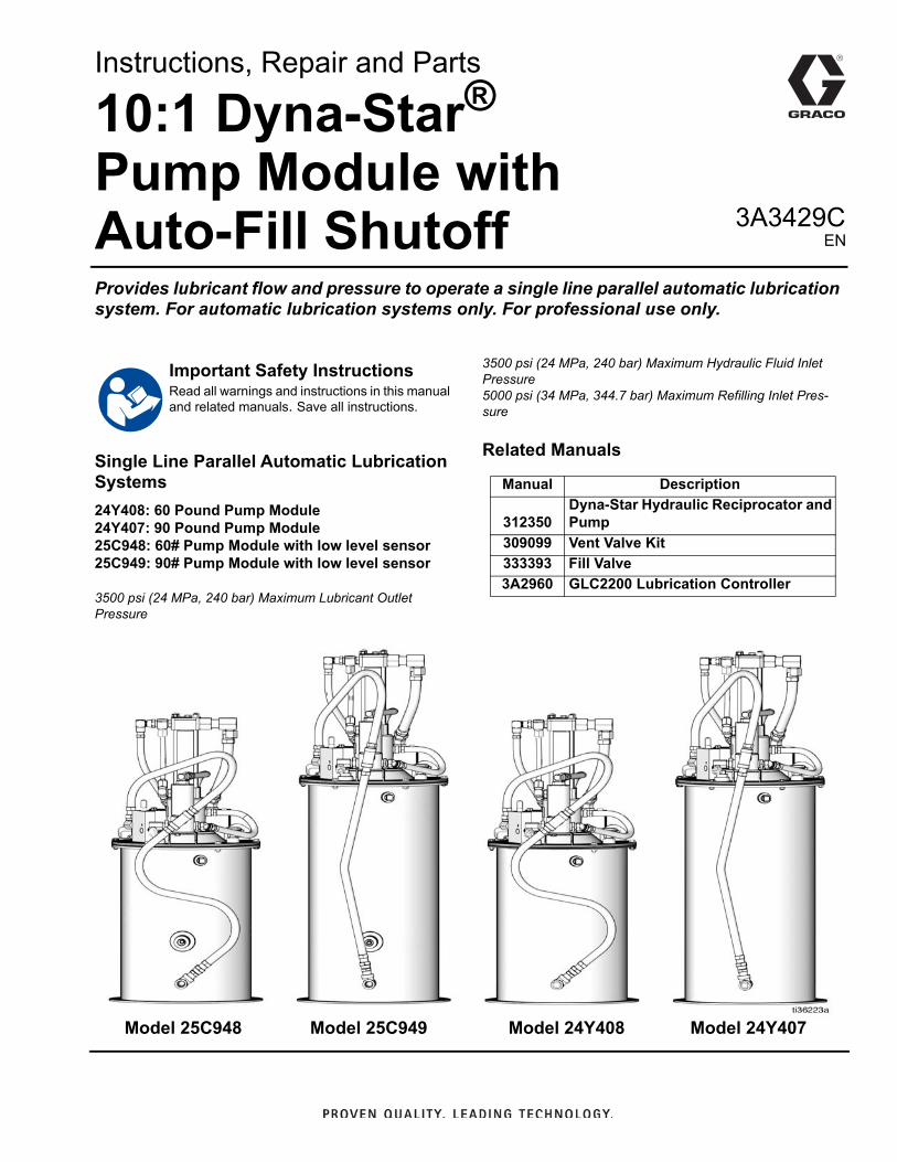
3A3429C Instructions, Repair and Parts 10:1 Dyna-Star ® Pump Module with Auto-Fill Shutoff Provides lubricant flow and pressure to operate a single line parallel automatic lubrication system. For automatic lubrication systems only. For professional use only. Single Line Parallel Automatic Lubrication Systems 24Y408: 60 Pound Pump Module 24Y407: 90 Pound Pump Module 25C948: 60# Pump Module with low level sensor 25C949: 90# Pump Module with low level sensor 3500 psi (24 MPa, 240 bar) Maximum Lubricant Outlet Pressure 3500 psi (24 MPa, 240 bar) Maximum Hydraulic Fluid Inlet Pressure 5000 psi (34 MPa, 344.7 bar) Maximum Refilling Inlet Pres- sure Related Manuals Important Safety Instructions Read all warnings and instructions in this manual and related manuals. Save all instructions. Manual Description 312350 Dyna-Star Hydraulic Reciprocator and Pump 309099 Vent Valve Kit 333393 Fill Valve 3A2960 GLC2200 Lubrication Controller Model 24Y408 Model 24Y407 Model 25C949 Model 25C948 EN
Transcript of Instructions, Repair and Parts 10:1 Dyna-Star Pump …...3A3429C Instructions, Repair and Parts 10:1...
3A3429C
Instructions, Repair and Parts
10:1 Dyna-Star® Pump Module with Auto-Fill ShutoffProvides lubricant flow and pressure to operate a single line parallel automatic lubrication system. For automatic lubrication systems only. For professional use only.
Single Line Parallel Automatic Lubrication Systems
24Y408: 60 Pound Pump Module24Y407: 90 Pound Pump Module25C948: 60# Pump Module with low level sensor25C949: 90# Pump Module with low level sensor
3500 psi (24 MPa, 240 bar) Maximum Lubricant Outlet Pressure
3500 psi (24 MPa, 240 bar) Maximum Hydraulic Fluid Inlet Pressure5000 psi (34 MPa, 344.7 bar) Maximum Refilling Inlet Pres-sure
Related Manuals
Important Safety InstructionsRead all warnings and instructions in this manual and related manuals. Save all instructions.
Manual Description
312350Dyna-Star Hydraulic Reciprocator and Pump
309099 Vent Valve Kit
333393 Fill Valve
3A2960 GLC2200 Lubrication Controller
Model 24Y408 Model 24Y407Model 25C949Model 25C948
EN

Table of Contents
2 3A3429C
Table of Contents
Warnings . . . . . . . . . . . . . . . . . . . . . . . . . . . . . . . . . 3
Installation . . . . . . . . . . . . . . . . . . . . . . . . . . . . . . . . 5
Grounding . . . . . . . . . . . . . . . . . . . . . . . . . . . . . . 5
Pump Module . . . . . . . . . . . . . . . . . . . . . . . . . . . 5
Typical Installation (with pressure relief valve). . . 7
Low Level Sensor . . . . . . . . . . . . . . . . . . . . . . . . 8
Typical Installation (with fill valve) . . . . . . . . . . . 10
Operation . . . . . . . . . . . . . . . . . . . . . . . . . . . . . . . . 12
Pressure Relief Procedure . . . . . . . . . . . . . . . . 12
Pump Module Operation . . . . . . . . . . . . . . . . . . 12
Auto-Fill Shut Off (S) . . . . . . . . . . . . . . . . . . . . . 13
Refilling the Reservoir . . . . . . . . . . . . . . . . . . . . 13
Shut Down . . . . . . . . . . . . . . . . . . . . . . . . . . . . 15
Service . . . . . . . . . . . . . . . . . . . . . . . . . . . . . . . . . . 16
Troubleshooting . . . . . . . . . . . . . . . . . . . . . . . . . . 16
Parts Drawing . . . . . . . . . . . . . . . . . . . . . . . . . . . . 18
Parts List . . . . . . . . . . . . . . . . . . . . . . . . . . . . . . . . 20
Technical Data . . . . . . . . . . . . . . . . . . . . . . . . . . . . 22
Dimensions . . . . . . . . . . . . . . . . . . . . . . . . . . . . . . 23
Graco Information . . . . . . . . . . . . . . . . . . . . . . . . . 24

Warnings
3A3429C 3
Warnings
The following warnings are for the setup, use, grounding, maintenance, and repair of this equipment. The exclama-tion point symbol alerts you to a general warning and the hazard symbols refer to procedure-specific risks. When these symbols appear in the body of this manual or on warning labels, refer back to these Warnings. Product-specific hazard symbols and warnings not covered in this section may appear throughout the body of this manual where applicable.
FIRE AND EXPLOSION HAZARD
When flammable fluids are present in the work area, such as gasoline and windshield wiper fluid, be aware that flammable fumes can ignite or explode. To help prevent fire and explosion:• Use equipment only in well ventilated area.• Eliminate all ignition sources, such as cigarettes and portable electric lamps.• Ground all equipment in the work area.• Keep work area free of debris, including rags and spilled or open containers of solvent and gasoline.• Do not plug or unplug power cords or turn lights on or off when flammable fumes are present.• Use only grounded hoses.• Stop operation immediately if static sparking occurs or you feel a shock. Do not use equipment until
you identify and correct the problem.• Keep a working fire extinguisher in the work area.
SKIN INJECTION HAZARD
High-pressure fluid from dispensing device, hose leaks, or ruptured components will pierce skin. This may look like just a cut, but it is a serious injury that can result in amputation. Get immediate surgical treatment.• Do not point dispensing device at anyone or at any part of the body.• Do not put your hand over the fluid outlet.• Do not stop or deflect leaks with your hand, body, glove, or rag.• Follow the Pressure Relief Procedure when you stop dispensing and before cleaning, checking, or
servicing equipment. • Tighten all fluid connections before operating the equipment.• Check hoses and couplings daily. Replace worn or damaged parts immediately.
TOXIC FLUID OR FUMES HAZARD
Toxic fluids or fumes can cause serious injury or death if splashed in the eyes or on skin, inhaled, or swallowed.• Read Safety Data Sheet (SDS) to know the specific hazards of the fluids you are using.• Store hazardous fluid in approved containers, and dispose of it according to applicable guidelines.

Warnings
4 3A3429C
EQUIPMENT MISUSE HAZARD
Misuse can cause death or serious injury.• Do not operate the unit when fatigued or under the influence of drugs or alcohol.• Do not exceed the maximum working pressure or temperature rating of the lowest rated system com-
ponent. See Technical Data in all equipment manuals.• Use fluids and solvents that are compatible with equipment wetted parts. See Technical Data in all
equipment manuals. Read fluid and solvent manufacturer’s warnings. For complete information about your material, request Safety Data Sheet (SDS) from distributor or retailer.
• Turn off all equipment and follow the Pressure Relief Procedure when equipment is not in use.• Check equipment daily. Repair or replace worn or damaged parts immediately with genuine manu-
facturer’s replacement parts only.• Do not alter or modify equipment. Alterations or modifications may void agency approvals and create
safety hazards.• Make sure all equipment is rated and approved for the environment in which you are using it.• Use equipment only for its intended purpose. Call your distributor for information.• Route hoses and cables away from traffic areas, sharp edges, moving parts, and hot surfaces.• Do not kink or over bend hoses or use hoses to pull equipment.• Keep children and animals away from work area.• Comply with all applicable safety regulations.
MOVING PARTS HAZARD
Moving parts can pinch, cut or amputate fingers and other body parts.• Keep clear of moving parts.• Do not operate equipment with protective guards or covers removed.• Pressurized equipment can start without warning. Before checking, moving, or servicing equipment,
follow the Pressure Relief Procedure and disconnect all power sources.
BURN HAZARDEquipment surfaces and fluid that is heated can become very hot during operation. To avoid severe burns:• Do not touch hot fluid or equipment.
PERSONAL PROTECTIVE EQUIPMENT
Wear appropriate protective equipment when in the work area to help prevent serious injury, including eye injury, hearing loss, inhalation of toxic fumes, and burns. Protective equipment includes but is not limited to:• Protective eyewear, and hearing protection. • Respirators, protective clothing, and gloves as recommended by the fluid and solvent manufacturer.

Installation
3A3429C 5
InstallationRead and follow instructions supplied with each system component.
Grounding
For Mobile Installations
Mount reservoir (K) (FIG. 2, page 7) to a grounded chas-sis member.
For Non-mobile Installations (FIG. 1)1. Remove ground screw (gs) and insert through eye
in ring terminal at the end of the ground wire.
2. Fasten ground screw (gs) back into pump and tighten securely.
3. Connect other end to a true earth ground.
Pump Module Mount the reservoir (K) on sturdy, flat surface with 6 (six), 3/8-inch diameter bolts. Locate the high pressure lubricant supply lines (W) and hydraulic lines (T and G) for easy access once installed.
• The hydraulic system must be depressurized before connecting high pressure lubricant supply lines (W).
• Be sure breather (J) is not plugged before filling res-ervoir (K).
• The hydraulic oil supply must be 10µ filtered or better and supply 0.5 - 3.0 gpm (1.9 - 11.4 lpm) at 300 psi - 3500 psi (21 bar - 241 bar (2.1 MPa - 24 MPa).
1. Install Ball Valve (A) (user provided) in the 3/8-inch High Pressure Hydraulic Line (G) (FIG. 2, page 7).
2. Connect the 3/4-inch hydraulic tank line (T) (FIG. 2, page 7) to the tank hydraulic connection swivel (PP) (FIG. 9, page 11).
3. Connect the 24 VDC timer controlled signal to the 3-way solenoid valve (JJ) (FIG. 9, page 11).
4. Connect high pressure lubricant supply line (W) (FIG. 2, page 7) to the lubricant output connection (CC) (FIG. 8, page 11).
5. Ground system (see Grounding).
6. Connect the 3/8-inch high pressure hydraulic line (G) (FIG. 2, page 7) to the high pressure hydraulic connection swivel (Y) (FIG. 9, page 11).
Inlet and Outlet Components
LIFTING HAZARDThis equipment is heavy. Lifting or moving heavy equipment incorrectly can cause serious injury such as muscle strain or back injuries. To avoid injury:• Do not lift or move this equipment without assis-
tance.• Always use a lifting device secured to the pump lift
ring when moving or installing this equipment. See Technical Data, page 22 for pump weight.
The equipment must be grounded to reduce the risk of static sparking. Static sparking can cause fumes to ignite or explode. Grounding provides an escape wire for the electric current.
FIG. 1gs
COMPONENT RUPTURE HAZARDThe maximum working pressure of the inlet and outlet components in the system vary. Over-pressurizing an inlet or outlet can cause it to rupture resulting in prop-erty damage and serious injury such as skin injection or injury from splashing fluid. To reduce the risk of component rupture: • Be sure to know the maximum working pressure of
each inlet and outlet component in the system.• Never exceed the maximum working pressure of
the inlet and outlet components.

Installation
6 3A3429C
Setting the Hydraulic Pressure and Flow Rate
1. Set the hydraulic pump pressure to the lowest pres-sure needed using the pressure reducing valve (NN). This setting should be between 250 - 350 psi (1.7 to 2.4 MPa, 17.0 to 24.1 bar).
2. Set the hydraulic flow rate to pump at lowest rate/cycles needed using flow control valve (KK) to get desired pump speed.
3. With a primed pump and sufficient hydraulic supply, the pump starts when the timer activates the sole-noid valve. The pump stops when the timer deacti-vates the solenoid valve.
Refilling Line (D) Requirements
To relieve the stall pressure in the refilling line (D) a pressure relief valve (H) (FIG. 2, page 7) or a fill valve (Z) (FIG. 7, page 10) must be installed in the system.
Systems without Fill Valve
A pressure relief valve (H) and overflow container (N) for collecting excess fluid that drains during pressure relief, must be installed in an easily accessible location between the remote filling station pump (P) and the Auto-Fill Shut Off (S). This pressure relief valve is used to relieve pressure in the refilling line (D) and to reset the Auto-Fill Shut Off. See Typical Installation, page 7.
A Pressure Relief Kit: 247902 is available from Graco. Contact your distributor or Graco Customer Service for additional information about this kit.
Systems with Fill Valve (Z)
Install the fill valve (Z) in an easily accessible location between the remote fill station pump (P) and Auto-Fill Shut Off Valve (S). See Typical Installation, page 8.
The fill valve is used to relieve pressure in the refilling line (D) and to reset the Auto-Fill Shut Off (S). See the fill valve instruction manual 333393. Graco fill valve, part no. 77X542 is available. Contact your local Graco dis-tributor.
Refilling Pump (P) Requirements
The remote filling station pump stalls (dead-heads) when the reservoir is full, causing the supply system pressure to rise to the maximum output pressureof the filling station pump. To help prevent equip-ment damage or serious injury caused by pressur-ized fluid, such as skin injection or injury from splashing fluid, always use a remote filling station pump with a maximum output pressure of 5000 psi (34 MPa, 344.7 bar) and use a refill line with a pressure rating equal to or greater than the refill pump.

Installation
3A3429C 7
Typical Installation Systems with Pressure Relief Valve in the Refilling Line
The installation shown is only a guide for selecting and installing system components. Contact your Graco distributorfor assistance in planning a system to suit your needs.
NOTE: The remote filling station pump stalls (dead-heads) when the reservoir is full. If the pump does not stall (dead-head) there is a leak in the system.
Key:A Pump B Ignition switchC Refilling LineD Injector banksE Lubrication controllerF Pressure Relief Valve*G BreatherH ReservoirI Vent ValveJ Filter (recommended if grease/environment is
contaminated)K Fluid overflow container*L Pump - remote filling stationM Reservoir - remote filling stationN Auto-Fill Shut OffO High-pressure lubricant supply line
P Low level sensor
* A pressure relief valve (F) and overflow container (K) for col-lecting excess fluid that drains during pressure relief must be installed in an easily accessible location between the remote filling station pump (L) and the Auto-Fill Shut Off (N). This pressure relief valve is used to relieve pressure in the refilling line and to reset the Auto-Fill Shut Off.
FIG. 2
D O
B
E
M
L
K
H
N
A
F
G
J I
C
P

Installation
8 3A3429C
Low Level SensorWhen grease is present the LED is green. When the lubricant level in the reservoir reaches approximately 30% (low level), the LED turns to an amber color. See FIG. 3 and the table below.
At 30% capacity, the amber low level signals the tank is reaching a point where the operator should refill the tank. There is still lubricant in the tank and immediate shutdown in not required.
If you are using a GLC2200 (part number 24N468, Series F or later only), the system will enter a low level warning condition (LL03) after the switch input is closed for more than 1 second. However, the pump continues to operate.
FIG. 3
Keep the sensor protective cover (12c on page 17) installed to prevent sensor damage.
Low level sensor wiring instructions begin below.
Graco GLC2200 (part number 24N468, Series F or later only) can be used to run the pump and monitor the low level. Refer to FIG. 5 for Low Level Sensor wiring in sys-tems controlled with a GLC2200. A Low Level Sensor cable (part number 129072) and a GLC2200 Wiring Harness (part number 24P314) are required.
Condition LED ColorOut 2 (Pin #2)(See Fig. 12, )
Grease present Green 0VDC
No grease present Amber 24 VDC

Installation
3A3429C 9
Low Level Sensor Wiring with GLC2200 Lube Controller
Sensor behaves as a source style sensor
Low Level Sensor Wiring with GLC4400
FIG. 4
Pin Connector
FIG. 5
FIG. 6

Installation
10 3A3429C
Typical Installation
Systems with Fill Valve in the Refilling Line
The installation shown is only a guide for selecting and installing system components. Contact your Graco distributor for assistance in planning a system to suit your needs.
NOTE: The remote filling station pump stalls (dead-heads) when the reservoir is full. If the pump does not stall (dead-head) there is a leak in the system.
Key:D Refilling Line T Pressure Relief LineV Instruction LabelZ Fill ValveZ1 Pressure Relief Knob
NOTE: The components highlighted in FIG. 7 identify the unique features in a Fill Valve installation. See Typical Installa-tion on page 7 for a complete list of the other system compo-nents.
Install the fill valve (Z) in an easily accessible location between the remote fill station pump (P) and Auto-Fill Shut Off Valve (S).
The fill valve is used to relieve pressure in the refilling line and to reset the Auto-Fill Shut Off.
FIG. 7
Z
T
D
Z1V

Installation
3A3429C 11
Vent Valve Connection P
Key:AA Vent Valve hydraulic control lineBB Pump output connection lineCC Lubricant outputDD Pressure relief valveEE Vent valveFF Vent lineSS Refilling lineS Auto-Fill Shut Off
Control Module Connection
Key:GG Pump tank lineHH Pump high pressure hydraulic lineJJ 3-way solenoid valveKK Flow control valveLL Vent valve hydraulic controlMM Regulated hydraulic pressure gaugeNN Pressure reducing valvePP Hydraulic tank connection (swivel)Y High pressure hydraulic connection (swivel)
*coil should always be installed with lettering facing out
FIG. 8
AA
EE
BBDD
CC FF
S
SS
FIG. 9
MM
*
LL
NN KK
PP
JJ
HH
GG
Y
Operation
12 3A3429C
OperationNOTE: Unless otherwise noted, the reference letters used in the following instructions refer to FIG. 2, page 7.
Pressure Relief ProcedureFollow the Pressure Relief Procedure whenever you see this symbol.
1. Disable hydraulic supply to pump (B) by isolating it from the high pressure hydraulic supply using ball valve (A).
2. Do one of the following:
• Cycle the timer [lubrication controller (F)] to open the 3-way solenoid valve to reduce trapped hydraulic pressure.
or
• Open pressure reducing valve (NN) to reduce trapped hydraulic pressure (FIG. 9, page 11).
NOTE: The gauge (MM) on control module should read zero pressure after performing this step.
3. Disconnect power from lubrication controller (F).
4. Relieve pressure in high pressure supply lines (W) using two wrenches working in opposite directions to slowly loosen fitting only until fitting is loose and no more lubricant or air is leaking from fitting.
Pump Module Operation
Pump Modules for injector-based, Automatic Lubri-cation Systems: provide lubricant flow and pressure to operate a single line parallel automatic lubrication sys-tem. The module requires a hydraulic power supply and a timed signal from a lubrication controller. Based on these signals, the pump module provides lubricant flow and pressure to operate the injectors and vents the injector system to reset the injectors.
1. Upon receiving a signal from a 24-volt lubrication controller (F), the 3-way solenoid valve opens, start-ing the pump (B) and closes the vent valve (L).
2. The pump builds pressure until the pressure switch in the system sends a signal to the lubrication con-troller (F) ending the cycle, or the pump (B) stalls.
3. The lubrication controller (F) terminates the 24-volt signal to the 3-way solenoid valve.
4. The 3-way solenoid valve closes, stopping the pump (B) and opening the vent valve (L) into the reservoir (K).
5. The pressure reducing valve (NN) and flow control valve (KK) control the pump output pressure and cycle rate (FIG. 9, page 11).
This equipment stays pressurized until pressure is manually relieved. To help prevent serious injury from pressurized fluid, such as skin injection, splashing fluid and moving parts, follow the Pressure Relief Pro-cedure when you stop dispensing and before clean-ing, checking, or servicing the equipment.
NOTICE
Never allow pump to run dry of the fluid being pumped. A dry pump will quickly accelerate to a high speed, possibly damaging the pump. If your pump accelerates quickly, or is running too fast, stop the pump immediately and check the fluid supply.

Operation
3A3429C 13
Auto-Fill Shut Off (S) The Auto-Fill Shut Off (S) is used for refilling the grease tank/reservoir in an automatic lubrication system.
NOTE: For systems without a fill valve, see Refilling Systems without a Fill Valve instructions beginning on page 13. For systems with a fill valve, see Refilling Systems with a Fill Valve beginning on page 14.
As grease is added to the reservoir, it pushes the dia-phragm up to the top of the reservoir. The diaphragm then pushes the valve pin and closes the inlet fluid path.
When the fluid refilling path closes, the refilling line (D) pressurizes and brings the refilling pump (P) to a pres-surized stall condition.
NOTE: The operator must monitor system while filling tank to reduce the risk of accidental fluid overflow.
Refilling the Reservoir
Refilling Systems without a Fill Valve
1. Connect refilling line (D) from remote filling station pump (P) to the Auto-fill Shutoff inlet (FIG. 2, page 7).
2. Turn on remote filling station pump (P) and fill reser-voir (K) until the indicator pin on the Auto-Fill Valve (S) pushes up as shown in FIG. 10. Pressure in the refill pump (P) builds and the pump stalls.
3. Turn off air supply to refill pump (P).
4. Relieve pressure between the remote filling station pump (P) and the Auto-Fill Shut Off (S):
a. Open ball valve (bv) (FIG. 11). Pressure will be
released and excess fluid will drain out of the
drain tube (dt) and into the lubrication collection
container (N).
FIG. 10
pinup
S
FIG. 11: In line installation shown
bv
G
dt
H
Operation
14 3A3429C
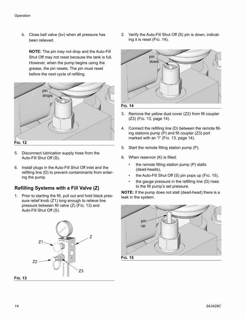
b. Close ball valve (bv) when all pressure has
been relieved.
NOTE: The pin may not drop and the Auto-Fill
Shut Off may not reset because the tank is full.
However, when the pump begins using the
grease, the pin resets. The pin must reset
before the next cycle of refilling.
5. Disconnect lubrication supply hose from the Auto-Fill Shut Off (S).
6. Install plugs in the Auto-Fill Shut Off inlet and the refilling line (D) to prevent contaminants from enter-ing the pump.
Refilling Systems with a Fill Valve (Z)
1. Prior to starting the fill, pull out and hold black pres-sure relief knob (Z1) long enough to relieve line pressure between fill valve (Z) (FIG. 13) and Auto-Fill Shut Off (S).
2. Verify the Auto-Fill Shut Off (S) pin is down, indicat-ing it is reset (FIG. 14).
3. Remove the yellow dust cover (Z2) from fill coupler (Z3) (FIG. 13, page 14).
4. Connect the refilling line (D) between the remote fill-ing stations pump (P) and fill coupler (Z3) port marked with an “I” (FIG. 13, page 14).
5. Start the remote filling station pump (P).
6. When reservoir (K) is filled:
• the remote filling station pump (P) stalls (dead-heads),
• the Auto-Fill Shut Off (S) pin pops up (FIG. 15),
• the gauge pressure in the refilling line (D) rises to the fill pump’s set pressure.
NOTE: If the pump does not stall (dead-head) there is a leak in the system.
FIG. 12
FIG. 13
pindrops
Z1
Z2
Z3
Z
FIG. 14
FIG. 15
pindown
pinup

Operation
3A3429C 15
7. Relieve pressure between remote filling station pump (P) and the fill valve (Z):
a. Turn off the remote filling station pump (P).
b. Pull out and hold black pressure relief knob (Z1)
long enough to relieve line pressure between fill
valve (Z) and Auto-Fill Shut Off Valve (S) and
between the remote filling station pump (P) and
fill valve (Z).
NOTE: The length of time it takes to vent varies depend-ing on the system design and installation. In some installations it may be necessary to repeat Step b to ensure pressure is relieved.
c. Disconnect the refilling line (D) at the fill coupler
(Z3).
d. Replace the yellow dust cover (Z2).
Shut Down(For these instructions, see FIG. 2, page 5).
1. For normal system shut down, disconnect power to lubricator controller (F) by turning off the ignition switch.
2. Turn of hydraulic supply by closing ball valve (A).

Service
16 3A3429C
ServiceUse only Genuine Graco Repair Parts.
See separate system component manuals for service instructions. For pump service see manual 312350. For vent valve service see manual 309099.
Troubleshooting
Problem Cause Solution
System does not build sufficient pres-sure.
Pump (B) malfunction. Refer to manual 312350.
Pump (B) turned off too soon. Increase lubrication controller (F) “pump on” setting.
Increase hydraulic flow rate to pump (F).
Solenoid (JJ) malfunction. Repair or replace solenoid (JJ).
Too low or no hydraulic supply. Turn pressure up or supply on.
Vent valve (L) seal failure. Replace seal.
Vent valve (L) needle/seat failure. Replace needle and seat.
Reservoir (K) out of grease. Fill reservoir (K).
Broken or leaky supply/branch line. Tighten connections and/or replace line(s).
Injector failure. Repair or replace injector.
Pressure in tank line too high due to restrictions in tank line or plumbing too small.
Remove tank line restrictions.
Use larger plumbing.
Lubricant dispensed from pressure relief valve.
System pressure set too high. Decrease hydraulic pressure to pump.
Pump (B) runs too fast. Reservoir (K) out of lubricant. Fill reservoir (K).
Leak in distribution system. Repair leak.
Lubricant coming out of breather (J). Reservoir (K) overfilled because Auto-Fill Shut Off (S) did not shut the refilling line (D).
Replace the Auto-Fill Shut Off (S) diaphragm (9) and Auto-Fill Shut Off valve (8).

Troubleshooting
3A3429C 17
Pump (B) will not start. No hydraulic supply. Verify/check hydraulic supply.
Solenoid (JJ) malfunction. Replace solenoid (JJ).
No electrical supply to lubrication controller (F).
Turn on electrical supply.
Lubrication controller (F) malfunction. Refer to lubrication controller man-ual.
Pump (B) malfunction. Refer to pump manual 312350.
Refilling pump (P) slows down or stalls and no output at the fill valve (Z).
Auto-Fill Shut Off Valve (S) has not reset
Relieve all refilling line (D) pressure. see page 13.
Make sure Auto-Fill Shut Off (S) pin is down. See FIG. 14, page 14.
Refilling pump (P) runs continuously but does not stall.
Leakage in the system Inspect the refilling line (D) and cor-rect any leaks.
Problem Cause Solution

Parts Drawing
18 3A3429C
Parts Drawing
(See Parts List, page 20)
Pump hydraulic outlet
Pump hydraulic inlet
13j
3l
3k
3i
3d
3a
3g
3c
3f
3h
3e
7
3b
8
5, 6
2
2m
3a
3l
4
9
10
11 2m
12c
12b
12a

Parts Drawing
3A3429C 19
Parts DrawingVent Valve Kit (2): 243170Control Module Kit (4): 247538
To pump hydraulic inlet
To pump
To pumplubricant outlet
4m
4q4u
4t
4c*
4d*
4e*
4a*
4n
4j
4b
4h*
4f*
4g*
4r
4n
4k
2h
2n
2g2b
2p
2e
2c2i
2d
2a
2f
2m
3a3b
2q
4a*/4h* Torque 40-43 ft-lbs (54-58 Nm)
4c*/4e* Torque 15-20 ft-lbs (20-27 Nm)
4d* Torque 20-25 ft-lbs (27-34 Nm)
4f* Torque 68-75 ft-lbs (92-102 Nm)
4g* Torque 22-24 ft-lbs (30-33 Nm)
4s* Allows user to plug vent line for use in systems without a vent valve
* Lubricate o-ring with oil before installation
hydraulic outlet
4s*

Parts List Model 24Y408: Dyna-Star 10:1 Pump Module, 60# for Single Line, Parallel, Automatic Lubrication Systems
Model 24Y407: Dyna-Star 10:1 Pump Module, 90# for Single Line, Parallel, Automatic Lubrication Systems
Ref. No.
Part No. Description Qty
1247540
PUMP, Dyna-Star 60#, see manual 312350
1247443
PUMP, Dyna-Star 120#, see manual 312350
2 243170 KIT, installation, vent valve 1
2a 100505 . BUSHING, pipe 1
2b 100840 . ELBOW, street 1
2c 100896 . FITTING, bushing, pipe 1
2d . SCREW, cap, hex hd 2
2e 115122 . VALVE, pressure relief 1
2f 161889 . UNION, adapter 1
2g 157705 . UNION, swivel 1
2h 158212 . BUSHING 1
2i 155470 . UNION, union, swivel, 90 degree 1
2m 194995 . HOSE, vent; 1/2 in. 2
2n 238370 . HOSE 2
2p 242063 . VALVE, vent 1
2q 156684 . UNION, adapter 1
325C948
Pump Module, 60#, AFSO, LL, grease
1
25C949Pump Module, 90#, AFSO, LL, grease
1
3a 100737 . PLUG, pipe 2
3b 108126 . TEE, pipe 1
3c . NUT, flanged, hex 6
3d . SCREW, cap, flange head 4
3e 115254 . BREATHER 1
3f 194868 . GASKET, cover 1
3g15R105
. PAIL, reservoir, 60#, models 24Y408
1
194907 . PAIL, reservoir, 90#, models 24Y407
1
3h 16X912 . COVER, reservoir 1
3i 104663 . PLUG, pipe 1

Parts List
3A3429C 21
* Installation kits for custom user provided lubricant res-ervoirs not shown.
3j 101864 . SCREW, cap 4
3k 15M442 . GASKET, pump 1
3l 100214 . WASHER, lock 6
4 247538 KIT, installation control module 1
4a 112581 . ADAPTER, male 1
4b 121207 . MODULE, hydraulic control 1
4c . VALVE, 3-way solenoid 1
4d . VALVE, flow regulating 1
4e 121206 . VALVE, pressure reducing 1
4f 115757 . ADAPTER, straight thread 1
4g 115758 . ADAPTER, straight thread 1
4h 115760 . ADAPTER, straight thread 1
4j 115763 . ADAPTER, straight thread 1
4k 115776 . HOSE, 3/4 in. X 3/4 in. NPT 1
4m 115829 . UNION, swivel, 90 degree 1
4n 160327 . UNION, adapter 90 degree 2
4q 238370 . HOSE, coupled, 1 ft. 1
4r 802072 . GAUGE, pressure 1
4s 108984 . PLUG, hollow, hex 1
4t . WASHER, lock 6
4u . SCREW, cap, hex hd 2
5 TEE, pipe 1
6 ADAPTOR 1
7 217430 ADAPTOR 1
8 16V582 AUTO-FILL SHUTOFF 1
9 16V748 DIAPHRAM 1
10 16V396 SEAL, AUTO-FILL SHUTOFF 1
11 16X389 SCREW, cap, button head 2
12 17L392 Low level sensor 1
12a Packing, O-ring 1
12b Sensor, low level 1
12c ADAPTOR, cover 1
Ref. No.
Part No. Description Qty

Technical Data)
Pump Module with Auto-Fill Shutoff US Metric
Maximum hydraulic input pressure 3500 psi 24.0 MPa, 240 bar
Pump wetted parts see manual 312350
Vent valve wetted parts see manual 309099
Reservoir wetted parts steel, buna-n rubber
Maximum delivery @ 60 cpm 1.1 lb/min, 34.8 in3/min 570 cm3/min
Regulated hydraulic pressure operating range 250 to 350 psi 1.7 to 2.4 MPa, 17.0 to 24.1 bar
Hydraulic flow rate operating range 0.5 to 3.0 gpm 1.9 to 11.4 liter/min
Maximum hydraulic fluid temperature 200°F 93.33°C
Lubricant outlet pressure range 2500 to 3500 psi17.0 to 24.0 MPa, 170 to 240 bar
Fill port size - Auto-fill Shutoff 3/8 inch npt (FIG. 2, S, page 7)
Hydraulic inlet port size 3/8 inch nps swivel (FIG. 9, Y, page 11)
Hydraulic tank line size 3/4 inch nps swivel (FIG. 9, Z, page 11)
Lubricant outlet port size 1/2 inch nps swivel (FIG. 2 U, page 7)
Grease capacity
Model 24Y407, 25C949 90 lb. 41 kg
Model 24Y408, 25C948 60 lb. 27 kg
Mounting holes for pump module six, 7/16 inch holes on 13 7/8 inch bolt circle
Reservoir diameter 12 3/4 inch 324 mm
Pump module height
Model 24Y407, 25C949 42.75 inch 1086 mm
Model 24Y408, 25C948 35.15 inch 893 mm
Electrical requirements Timed 24 VDC signal
Electrical power requirements 14.7 Watts
Filtration (hydraulic fluid) 10µ (microns) or better
Sound Pressure* 77 dB(A)
*Sound pressure reading taken with pump operating at 66 cycles per minute. Sound pressure measured per CAGI-PNEUROP, 1971.

Dimensions
3A3429C 23
Dimensions
Lubricant Outlet1/2 inch nps swivel
Mounting Diagram ø15.0 inch(381 mm)
six, 7/16 inch holes15.0 inch(381 mm)
35.15 inch.(893 mm)
ti10646a
Model 24Y408
Model 24Y407
six, 7/16 inch holes13 7/8 inch bolt circle
42.75 inch(1086 mm)
15.0 inch(381 mm)
Mounting Diagramø15.0 inch
(381 mm)
13 7/8 inch bolt circle
Lubricant Outlet1/2 inch nps swivel
Model 25C948
Model 25C949

All written and visual data contained in this document reflects the latest product information available at the time of publication. Graco reserves the right to make changes at any time without notice.
Original instructions. This manual contains English. MM 3A3429Graco Headquarters: Minneapolis
International Offices: Belgium, China, Japan, Korea
GRACO INC. AND SUBSIDIARIES • P.O. BOX 1441 • MINNEAPOLIS MN 55440-1441 • USACopyright 2016, Graco Inc. All Graco manufacturing locations are registered to ISO 9001.
www.graco.comRevision C, August 2019
Graco Standard WarrantyGraco warrants all equipment referenced in this document which is manufactured by Graco and bearing its name to be free from defects in material and workmanship on the date of sale to the original purchaser for use. With the exception of any special, extended, or limited warranty published by Graco, Graco will, for a period of twelve months from the date of sale, repair or replace any part of the equipment determined by Graco to be defective. This warranty applies only when the equipment is installed, operated and maintained in accordance with Graco’s written recommendations.
This warranty does not cover, and Graco shall not be liable for general wear and tear, or any malfunction, damage or wear caused by faulty installation, misapplication, abrasion, corrosion, inadequate or improper maintenance, negligence, accident, tampering, or substitution of non-Graco component parts. Nor shall Graco be liable for malfunction, damage or wear caused by the incompatibility of Graco equipment with structures, accessories, equipment or materials not supplied by Graco, or the improper design, manufacture, installation, operation or maintenance of structures, accessories, equipment or materials not supplied by Graco.
This warranty is conditioned upon the prepaid return of the equipment claimed to be defective to an authorized Graco distributor for verification of the claimed defect. If the claimed defect is verified, Graco will repair or replace free of charge any defective parts. The equipment will be returned to the original purchaser transportation prepaid. If inspection of the equipment does not disclose any defect in material or workmanship, repairs will be made at a reasonable charge, which charges may include the costs of parts, labor, and transportation.
THIS WARRANTY IS EXCLUSIVE, AND IS IN LIEU OF ANY OTHER WARRANTIES, EXPRESS OR IMPLIED, INCLUDING BUT NOT LIMITED TO WARRANTY OF MERCHANTABILITY OR WARRANTY OF FITNESS FOR A PARTICULAR PURPOSE.
Graco’s sole obligation and buyer’s sole remedy for any breach of warranty shall be as set forth above. The buyer agrees that no other remedy (including, but not limited to, incidental or consequential damages for lost profits, lost sales, injury to person or property, or any other incidental or consequential loss) shall be available. Any action for breach of warranty must be brought within two (2) years of the date of sale.
GRACO MAKES NO WARRANTY, AND DISCLAIMS ALL IMPLIED WARRANTIES OF MERCHANTABILITY AND FITNESS FOR A PARTICULAR PURPOSE, IN CONNECTION WITH ACCESSORIES, EQUIPMENT, MATERIALS OR COMPONENTS SOLD BUT NOT MANUFACTURED BY GRACO. These items sold, but not manufactured by Graco (such as electric motors, switches, hose, etc.), are subject to the warranty, if any, of their manufacturer. Graco will provide purchaser with reasonable assistance in making any claim for breach of these warranties.
In no event will Graco be liable for indirect, incidental, special or consequential damages resulting from Graco supplying equipment hereunder, or the furnishing, performance, or use of any products or other goods sold hereto, whether due to a breach of contract, breach of warranty, the negligence of Graco, or otherwise.
FOR GRACO CANADA CUSTOMERSThe Parties acknowledge that they have required that the present document, as well as all documents, notices and legal proceedings entered into, given or instituted pursuant hereto or relating directly or indirectly hereto, be drawn up in English. Les parties reconnaissent avoir convenu que la rédaction du présente document sera en Anglais, ainsi que tous documents, avis et procédures judiciaires exécutés, donnés ou intentés, à la suite de ou en rapport, directement ou indirectement, avec les procédures concernées.
Graco Information
For the latest information about Graco products, visit www.graco.com.For patent information, see www.graco.com/patents. TO PLACE AN ORDER, contact your Graco distributor or call to identify the nearest distributor.Phone: 612-623-6928 or Toll Free: 1-800-533-9655, Fax: 612-378-3590