INSTRUCTIONS MANUAL FOR THE GAS...
42
Supermicra R 23 E 24 SE ATTENTION (for SUPERMICRA R 24 SE) FOR DIAPHRAGM POSITIONING, CAREFULLY READ THE FLUE SYSTEMS INSTRUCTIONS IN THE “INSTALLATION” CHAPTER. IMPORTANT THE FIRST IGNITION OF THE BOILER MUST BE EXECUTED BY AN AUTHORIZED TECHNICIAN ACCORDING TO THE LAW 46/90. Assigning all the operations for the first ignition to a Hermann Authorized Service Center the particular and exclusive Hermann Conventional Warranty is activated. For further information consult the coupon which you can find in the boiler’s documents envelope. Assigning all the operations for the first ignition to a Hermann Authorized Service Center the particular and exclusive Hermann Conven- tional Warranty is activated. For further information consult the coupon which you can find in the boiler’s documents envelope. INSTRUCTIONS MANUAL FOR THE GAS BOILER
Transcript of INSTRUCTIONS MANUAL FOR THE GAS...

Supermicra R23 E
24 SE
ATTENTION(for SUPERMICRA R 24 SE)
FOR DIAPHRAGM POSITIONING, CAREFULLY READ THE FLUE SYSTEMSINSTRUCTIONS IN THE “INSTALLATION” CHAPTER.
IMPORTANTTHE FIRST IGNITION OF THE BOILER MUST BE EXECUTED BY ANAUTHORIZED TECHNICIAN ACCORDING TO THE LAW 46/90.
Assigning all the operations for the first ignition to a Hermann Authorized ServiceCenter the particular and exclusive Hermann Conventional Warranty is activated.For further information consult the coupon which you can find in the boiler’sdocuments envelope.
Assigning all the operations for the first ignition to a Hermann Authorized Service Center the particular and exclusive Hermann Conven-tional Warranty is activated. For further information consult the coupon which you can find in the boiler’s documents envelope.
INSTRUCTIONS MANUALFOR THE GAS BOILER
2
sect
ions
for t
he u
ser
sect
ions
for t
he te
chni
cian
Index
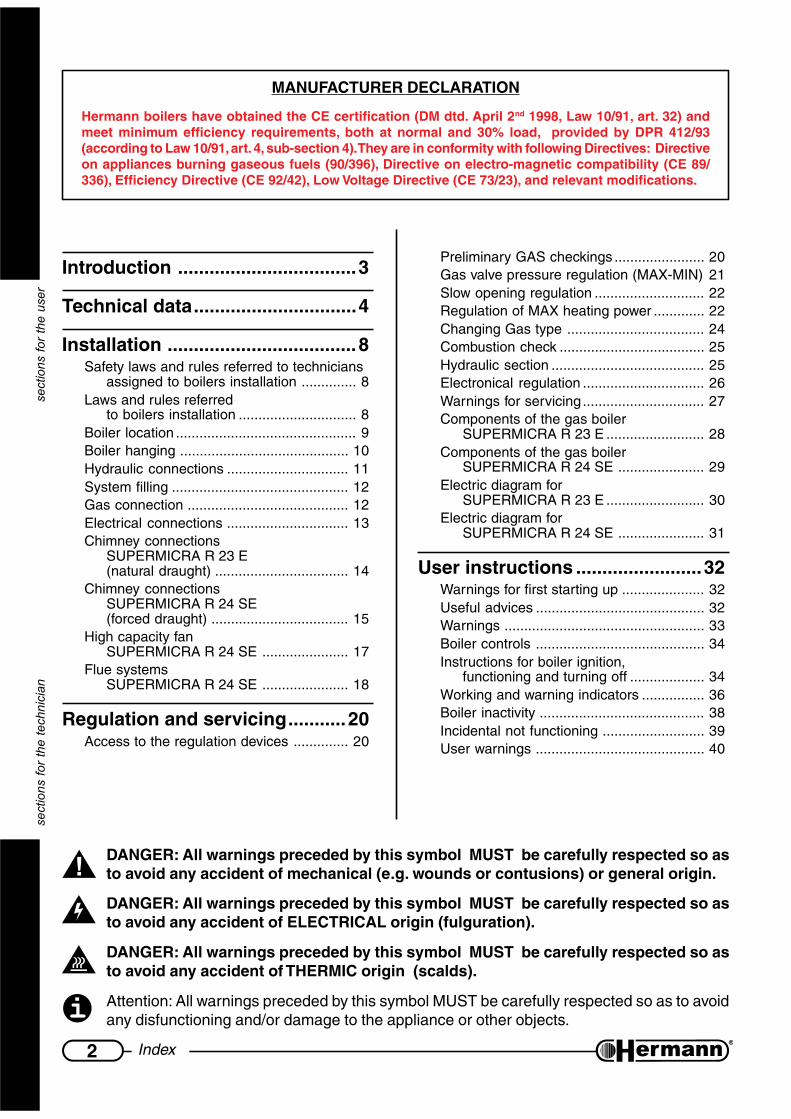
DANGER: All warnings preceded by this symbol MUST be carefully respected so asto avoid any accident of mechanical (e.g. wounds or contusions) or general origin.
DANGER: All warnings preceded by this symbol MUST be carefully respected so asto avoid any accident of ELECTRICAL origin (fulguration).
DANGER: All warnings preceded by this symbol MUST be carefully respected so asto avoid any accident of THERMIC origin (scalds).
Attention: All warnings preceded by this symbol MUST be carefully respected so as to avoidany disfunctioning and/or damage to the appliance or other objects.
Introduction ..................................3
Technical data...............................4
Installation ....................................8Safety laws and rules referred to technicians
assigned to boilers installation .............. 8Laws and rules referred
to boilers installation .............................. 8Boiler location .............................................. 9Boiler hanging ........................................... 10Hydraulic connections ............................... 11System filling ............................................. 12Gas connection ......................................... 12Electrical connections ............................... 13Chimney connections
SUPERMICRA R 23 E(natural draught) .................................. 14
Chimney connectionsSUPERMICRA R 24 SE(forced draught) ................................... 15
High capacity fanSUPERMICRA R 24 SE ...................... 17
Flue systemsSUPERMICRA R 24 SE ...................... 18
Regulation and servicing...........20Access to the regulation devices .............. 20
Preliminary GAS checkings ....................... 20Gas valve pressure regulation (MAX-MIN) 21Slow opening regulation ............................ 22Regulation of MAX heating power ............. 22Changing Gas type ................................... 24Combustion check ..................................... 25Hydraulic section ....................................... 25Electronical regulation ............................... 26Warnings for servicing............................... 27Components of the gas boiler
SUPERMICRA R 23 E ......................... 28Components of the gas boiler
SUPERMICRA R 24 SE ...................... 29Electric diagram for
SUPERMICRA R 23 E ......................... 30Electric diagram for
SUPERMICRA R 24 SE ...................... 31
User instructions ........................32Warnings for first starting up ..................... 32Useful advices ........................................... 32Warnings ................................................... 33Boiler controls ........................................... 34Instructions for boiler ignition,
functioning and turning off ................... 34Working and warning indicators ................ 36Boiler inactivity .......................................... 38Incidental not functioning .......................... 39User warnings ........................................... 40
MANUFACTURER DECLARATION
Hermann boilers have obtained the CE certification (DM dtd. April 2nd 1998, Law 10/91, art. 32) andmeet minimum efficiency requirements, both at normal and 30% load, provided by DPR 412/93(according to Law 10/91, art. 4, sub-section 4). They are in conformity with following Directives: Directiveon appliances burning gaseous fuels (90/396), Directive on electro-magnetic compatibility (CE 89/336), Efficiency Directive (CE 92/42), Low Voltage Directive (CE 73/23), and relevant modifications.

3Introduction
for
the
tech
nici
an a
nd fo
r th
e us
er
INTRODUCTIONThe instructions manual is an essential and complementary part of the product and it issupplied together with the boiler.
Carefully read the manual, achieving all important information for a safe installation,use and servicing.
— Carefully keep the manual for any further consultation you may need.
— The installation must be carried out by a qualified technician, in accordance withmanufacturer instructions and with the relevant requirements of the current issue.
— A qualified technician is a person with a specific technical competence in the field of theheating appliances for domestic use and domestic hot water production, as indicatedby the Law [ID of Your National rule, if any, regarding Technicians competence].
— User can ONLY make those operations that are specifically described in the “USERINSTRUCTIONS” section.
— The manufacturer has no contractual and extra-contractual responsibility for any damagearising from wrong installation, wrong use and non-observance of current laws andinstructions given by the manufacturer himself.
— Important: this gas boiler is used to heat the water at a temperature lower than the boiling one,at atmospheric pressure; it must be connected to an heating system in accordance with itsfeatures and power.
— Packing items (cartons, nails, plastic bags and so on) must not be left within childreneasy reach, as they are potentially dangerous.
— Before any cleaning or servicing operation, switch off the main electrical switch of theheating system and/or any other suitable switch providing electrical disconnection ofthe gas boiler.
— In case of fault and/or bad operation of the appliance, disconnect it immediately and donot try to repair it by yourselves.
Boiler servicing and repair must be carried out exclusively by [HERMANN Authorized ServicingCentres] [qualified technicians], which will use original spare parts. Strictly observe the aboverequirement, avoiding any risk of compromising the appliance safety.
— If the appliance should be definitively disconnected, remove or cut off any potential dangerousitem.
— When selling the appliance or leaving it installed after a removal, make always sure that theinstructions manual is close to the boiler for the future use of new owners and/or installers.
— This appliance must be used for its clearly recommended utilization only. Any other utilizationmust be considered dangerous and incorrect.
— It is strictly forbidden to use the appliance for different purposes than the specified ones.
— This appliance must be installed exclusively to wall.

4 Technical data
for
the
tech
nici
an
TECHNICAL DATAATADLACINHCET .M.U
RARCIMREPUSE32
RARCIMREPUSES42
noitacifitrecEC °n 0173NB4960 0173NB4960ssalC II +3H2 II +3H2
epyT SB/11B 24C-23C-21C-22B28C-26C-25C
epytsaG 02G /03G13G 02G /03G
13G
)iH(tupnitaehxaM Wk 6.52 6.52 6.52 6.52)iH(tupnitaehniM Wk 5.01 5.01 5.01 5.01
)iH(tuptuotaehxaM Wk 1.32 1.32 7.32 7.32)iH(tuptuotaehniM Wk 1.9 1.9 1.9 1.9
ON x ssalC 3 1 3 2ONdethgieW x hWk/gm 211 402 731 851
tupnilanimontaOC mpp 83 09 63 84OC 2 tupnilanimonta % 7.4 6.5 7.6 8
YCNEICIFFEycneiciffelanimoN % 8.09 2.39
daol%03taycneiciffE % 1.88 4.09GNITAEH
)xam÷nim(egnarnoitceleserutarepmeT C° 08÷03 08÷03lessevnoisnapxE l 8 8
erusserplessevnoisnapxE rab 1 1erusserpgnikrowxaM rab 3 3
erutarepmetmetsysxaM C° 58 58ATADLACIRTCELE
ycneuqerf/egatloV zH/V 05/032 05/032noitpmusnocrewoP
)nafyticapachgihhtiw=PAV( W 001 )PAV061(051
noitcetorpfoleveL D4XPI D4XPISNOISNEMID
htdiW htpeD-thgieH- mm margaid"SNOISNEMID"otrefeRthgieW gk 5.92 53
)teltuO=S(SNOITCENNOCnruter/wolfgnitaeH hcnI "¾ "¾telniretaWcitsemoD hcnI "½ "½
reliobehtotnoitcennocsaG hcnI "¾ "¾kcocsagehtotnoitcennocsaG
tiknoitcennocdradnatsfo hcnI "½ "½
ØteltuostcudorpeulF mm 031Øtelniria/teltuostcudorpeulflaixaoC mm 06/001
xam/nim)latnoziroh(htgneleulflaixaoC m 4÷5.0xam/nim)lacitrev(htgneleulflaixaoC m 5÷1
Øtelniria/teltuostcudorpeulfetarapeS mm 08
xam/nimhtgneleulfetarapeS m 03÷2)02=Sxam(
xam/nimhtgneleulfetarapeShtiw nafyticapachgih m 06÷13
)04=Sxam(htgneleulfetarapeS
xam/nimtilps-sepiphtiw m 41÷2)31=Sxam(
ERUSSERPYLPPUSSAG
epytsaG 02G /03G13G 02G /03G
13GerusserplanimoN rabm 02 73/92 02 73/92rebmunsrotcejnI 31 31 31 31
retemaidsrotcejnI Ømm001/1 021 57/57 021 57/57
NOITPMUSNOCSAG
xamQh/cm 17.2 17.2
h/gk /10.289.1
/10.289.1
nimQh/cm 11.1 11.1
h/gk /38.018.0
/38.018.0

5Technical data
for
the
tech
nici
an
ledomrelioBL
)mm(H
)mm(P
)mm(X
)mm(Y
)mm(Q
)mm(R
)mm(S
)mm(T
)mm(U
)mm(
E32RARCIMREPUS 004 057 743 702 391 491
ES42RARCIMREPUS 004 057 743 702 391 161 642 57 642 97
DIMENSIONS
1 teltuostcudorpeulF
2 metsyslaixaocroftelniriA
3 metsysetarapesroftelniriA
SuperSuperSuperSuperSupermicrmicrmicrmicrmicra R 24 SEa R 24 SEa R 24 SEa R 24 SEa R 24 SEmodel only:
SuperSuperSuperSuperSupermicrmicrmicrmicrmicra R (E - SE)a R (E - SE)a R (E - SE)a R (E - SE)a R (E - SE)
X
S T
1
2
3
Y
R
Q
69
6_
R0
1
L
X
P
QY
H
703
23
46
52 52 127 116.5 136
4
695_2_R01GTA / LFMR
R Heating return (3/4”)M Heating flow (3/4”)F Cold water inlet (1/2”)TA / L Zone for electrical power
supply and room thermostatconnections
G Gas (3/4”)

6 Technical data
for
the
tech
nici
an
772R01
AVAILABLE PUMP CAPACITY
with selector in speed position I, II, III (automatic by-pass, not disconnectable)
0
0,5
1
1,5
2
2,5
3
3,5
4
4,5
5
5,5
6
0 200 400 1000 1200600 800 1400
711
R00
Water flow l/h
Pre
ssur
e m
. H2O

7Technical data
for
the
tech
nici
an
BOILER SCHEMATIC SUPERMICRA R 23 ESUPERMICRA R 23 ESUPERMICRA R 23 ESUPERMICRA R 23 ESUPERMICRA R 23 E
SUPERMICRA R 24 SESUPERMICRA R 24 SESUPERMICRA R 24 SESUPERMICRA R 24 SESUPERMICRA R 24 SE
1 Drain valve2 Heating thermometer + gauge3 By-pass4 Pump5 Heating system safety valve 3 bar6 Expansion vessel7 Burner8 Primary heat exchanger9 Flue hood (“E” models)10 Flue thermostat (“E” models)11 Flue hood (“SE” models)12 Flue pressure switch (“SE” models)13 Fan (“SE” models)14 Safety thermostat15 Venting device16 NTC temperature sensor17 Filling valve18 Gas valve19 Loss of water switch
GAS
WAT
ERIN
LET
HEATING
FLOW
RETU
RN
GAS
WAT
ERIN
LET
HEATING
FLOW
RETU
RN
WARNING: This scheme is made for in-formation only. To make boiler hydrau-lic connection either use fixing jig or thedrawing inserted in the section “Instal-lation” or the “Dimensions” drawing.

8 Installation
for
the
tech
nici
an
INSTALLATION
Safety laws and rules referred to techniciansassigned to boilers installation
Place here all necessaryadvices according to national rules
about WORK SAFETYLaw number XXXX
“Actuation of 89/391/CEE; 89/655/CEE, 90/296/CEE, 90/934/CEE, 90/679/CEE, (work safety)”
Law number XXXX“Actuation of 89/686/CEE (21 Dec 1989)”
Other Law number XXXX (if any)“Other Law title and/or brief description”
Directives“Directive title and/or brief description”
Always proceed with caution when handling the boiler and carrying outinstallation/maintenance work as metal parts may cause injuries such as cutsand abrasions. Wear gloves while doing the above mentioned operations.
Laws and rules referredto boilers installation
Place here all necessaryadvices according to national rules
about BOILER INSTALLATIONLaw number XXXX
“Law title and/or brief description”

9Installation
for
the
tech
nici
an
Boiler locationINSTALLATION ROOM
When having an heat ouput lower than 35 kw (about 30000 Kcal/h), particular features for theinstallation room are not required. Shortly, all installation rules assuring a safe and regular gasboiler operation, must be strictly respected.
Place here all necessaryadvices according to national rules about:
- Installation room requirements- Limitations in power and/or number of boilers and other
appliances in the same roomLaw number XXXX
“Law title and/or brief description”
ROOM VENTILATION (mod. SUPERMICRA R 23 E – natural draught)
When a natural draught boiler is installed, permanent ventilation of the installationroom is mandatory and extremely important. Ventilation must be made and sized inaccordance with Laws and Rules in force.
INSTALLATION IN ROOMS WHERE TEMPERATURE CAN DROP DOWN TO 0°C:
When the installation place does not guarantee an adequate repair against atmospheric agents,the gas boiler must be completely protected through an adequate coverage as a safety measureagainst the above agents.
Thanks to its antifreeze system, inner components could never reach a temperature lower than5°C. This system is activated when the boiler is connected to the electrical and gas supply lines.
In case of boiler installation in rooms where temperature can drop down to 0°, it is advisable toprotect the heating circuit with an antifreeze liquid. See the “System Filling” section.
This appliance is not suitable for outdoor installation.

10 Installation
for
the
tech
nici
an
78
5
692_R
01
69
32.5
35
14
330
52 52 88
13
39 40 30 46.5 52.5
14
35
335
400
32.5
666
23
20
30
712
A A
B B
C
D
A1
B1
Boiler hangingREMARK: A re-utilizable metal jig can be ordered separately, so as to facilitate connections and
fixing points positioning (when the standard connection kit is used). If the standard connectionkit is not used, refer to the “Dimensions” drawing (Technical Data section) for the position of theconnections directly on the boiler.
— Consider gas boiler size and sufficient clearances [C] for servicing/repair. It is recommended:50mm on both lateral sides and 300 mm on lower side;
— To fix the boiler with wallplugs (“stud” type with nut), center the relevant wall holes as regards to[A] points. To hang it with open hooks, place hooks in correspondence with [B] points.
— Using the jig or respecting the measures indicated in the figure, fix up electrical connectionsand all ducts for heating flow and return, cold water and gas.
— Hang the boiler to the wallplugs or hooks, using the holes ([A1] for the wallplugs and [B1] for theopen hooks).
— Remove the plastic caps from the boilerconnections prior to connecting boiler tothe pipework.
REMARK: To facilitate boiler connection, it ispossible to remove temporarily the lowergrid, unscrewing its four screws.
— As far as air inlet and flue outlet ducts areconcerned (forced draught models),please refer to “Flue systems” paragraph,where measures are referred to the upperedge of boiler’s body [D].
Gas (1/2")
NOT USED onSUPERMICRA R models
Cold water INLET (1/2")
Heating RETURN (3/4")
Heating FLOW (3/4")
Electrical power supply
Room thermostat

11Installation
for
the
tech
nici
an
CONNECTION EXEMPLEHydraulic connectionsADVICES AND SUGGESTIONS TO AVOIDVIBRATIONS AND NOISES IN THE SYSTEM
— Do not use pipes with reduced diameters;
— Do not use bends with small radius andreductions of important sections;
— It is recommended an hot washing of thesystem in order to purge the pipes and theradiators from impurities (in particular oils andfats) that could damage the pump.
PUMP’S SPEED
The pump has a selector which allowsto reduce the speed, so as to reducethe noise produced by the too rapidcirculation of the liquids in too smallheating systems.
HEATING SYSTEM
— Considering that during boiler operation, the water inside the heating system increases itspressure, make sure that its maximum value does not exceed the maximum hydraulic pressureindicated on the technical data.
— Connect the safety evacuation ducts of the boiler to an evacuation funnel. If safety valves arenot connected to an evacuation device, their intervention could flood the room. Hermann cannotbe held responsible for any damage arising from that situation.
Make sure that the hydraulic and heating systems ducts are not used as earthconnections of the electrical system. They are absolutely NOT SUITABLE for such ause.
772R01

12 Installation
for
the
tech
nici
an
System fillingOnce all system connections have been carried out,proceed with system filling. This operation should bemade with caution, respecting the following steps:
— Open the radiators venting devices;
— Gradually open the water supply valve (see figure“Boiler bottom view”), checking the correctfunctioning of automatic venting devices,eventually installed;
— Close the radiators venting devices as soon aswater flows;
— Make sure that pressure gauge reaches the opti-mal value of 1÷1.5 bar (minimum: 0.5 bar);
— Close the water supply valve and bleed eachradiator;
In case the boiler is installed in rooms where temperature can drop down to 0°C, it is advisableto fill up the system with an anti-frost liquid.
Gas connectionBoiler installation must be carried out from a qualified technician, [as indicated by the Law XXXXX]because an incorrect installation can cause damages to people, animals or things, for which themanufacturer cannot be held responsible.
Verify what follows:
a) cleaning of all system gas pipes in order to avoid the presence of residual combustion productsthat could compromise the correct boiler functioning;
b) gas line and ramp conformity with laws and rules actually in force (Laws UNI-CIG 7129/01 and7131/99 – DM 12/04/96);
c) internal and external tightness of the gas system and connections;
d) supply pipe must have a section greater than or equal to the boiler one;
e) supply gas must correspond to the one for which the boiler has been regulated; otherwise, call[an HERMANN Servicing Centre] [a qualified technician] for gas conversion;
f) an interception valve must be installed upstream the appliance;
Open the meter valve and purge the air that is inside the system pipes (including all the appliances).
BOILER BOTTOM VIEW
FILLINGVALVE

13Installation
for
the
tech
nici
an
While connecting gas inlet pipe of the boiler to the pipe coming from gas network, it isMANDATORY to insert a TIGHT GASKET, whose dimensions and material must beadequate. Connection is NOT suitable for hemp, teflon strip or similar materials.
Using LPG, it is absolutely necessary to install a pressure reducer upstream the boiler.
Due to various installation possibilities, the gas cock supplied with Standard Connections Kit forSUPERMICRA boilers has a simple male Ø ½” connection, facing the rear of the boiler. No gaspipes are supplied.
Electrical connectionsThe link of the room thermostat works with a safety extra low voltage (SELV); connect it tothe voltage free terminals of the room thermostat/cronothermostat. On NO account mustany electrical voltage be applied to these terminals.
The boiler must be connected to an electrical line of 230V-50Hz, respecting the polarities L-N (Live-Neutral) and the earth connection.
PLACE UPSTREAM THE BOILER A BIPOLAR SWITCH in accordance with the rulesactually in force.
For the general electrical supply of the appliance, the use of adaptors, multiple taps and extensionsis not allowed.
If the supply cable must be replaced, use one of the following wire types: H05VVF or H05-VVH2-F.It is mandatory the earth connection in accordance with the rules actually in force. To replacethe cable, release the cable fastener placed on the frame of the hydraulic connections, open theback cover of the control panel and disconnect it from the terminals. Install the new cable workingin the reverse way. When connecting the cable to the boiler, it’s IMPORTANT:
— to leave the Earth wire about 2 cm longer than Live and Neutral wires;
— to lock tha cable in the cable fastener placed on the frame of the hydraulic connections.
Electrical safety of the appliance is only achieved when it is well connected to anefficient earthing system, executed as indicated by the safety rules actually in force.
A qualified technician must check that the electrical system is in line with the maximum powerallowed by the boiler, indicated on the data plate, with particular attention to the cables section.
Remark: HERMANN Ltd. declines any responsibility for damages to persons, animals orthings caused by the non-connection of the boiler earthing and by failure to comply withthe rules.

14 Installation
for
the
tech
nici
an
Chimney connectionsSUPERMICRA R 23 E(natural draught)
Place here all necessaryadvices according to national rules about
CHIMNEY CONNECTIONS of OPEN chamber boilers
FLUE
NO YES
These diagrams areto explain the mostimportant ITALIANlaws concerning
chimney connections(for EXEMPLEpurpose only)
PRODUCTS TEST POINT
2500 mm MAX
SLOPEmin 3%
2 x dmin
d

15Installation
for
the
tech
nici
an
Chimney connectionsSUPERMICRA R 24 SE(forced draught)NOTE ON FLUE INSTALLATION
When fitting air inlet and flue outlet horizontalducts, it is necessary to make sure there is a slopeof 2÷5% downwards from the boiler to the out-side (see diagram). This is essential to guaran-tee correct boiler operation and reliability. Air in-let and flue outlet terminals should be protectedby suitable approved flue accessories, to avoidenvironmental elements penetration.
Place here all necessaryadvices according to national rules about
CHIMNEY CONNECTIONS of sealed chamber boilers
FLUE
NO YES
2% ÷ 5%
631R01

16 Installation
for
the
tech
nici
an
AB
P
ON C
MF
E
DI
HL
G
tupnitaehriehtnognidneped,sreliobthguarddecrofrofslanimreteulffogninoitisoP
gninoitisoplanimreT secnatsiD
secnailppA
*Wk4morfWk7ot
mm.nim
Wk7morfWk61ot
mm.nim
Wk61morfWk53ot
mm.nim
wodniwarednU A 003 005 006
tnevrianarednU B 003 005 006
rettugarednU C 003 003 003
**ynoclabarednU D 003 003 003
wodniwtnecajdanamorF E 004 004 004
tnevriatnecajdanamorF F 006 006 006
***sepipnoitaucavelatnozirohrolacitrevmorF G 003 003 003
gnidliubehtforenrocamorF H 003 003 003
gnidliubehtfosseceramorF I 003 003 003
roolfrehtonamorfrodnuorgehtmorF L 004 0051 0052
yllacitrevslanimretowtneewteB M 005 0001 0051
yllatnozirohslanimretowtneewteB N 005 008 0001
ongnivah,ecafrusrehtonagnicafecafrusamorF.stm3foecnatsidanihtiwslanimretrosgninepo
elohnoitaucaveehtmorfO 0051 0081 0002
nihtiwslanimretrosgninepohtiwtub,evobasAelohnoitaucaveehtmorf.stm3foecnatsida
P 0052 0082 0003
* Appliances with an heat input lower than 4 Kw are not subjected to any limitation for the terminalspositioning, except for the points O and P.
** The terminals under a practicable balcony must be positioned in such a way that the total flue run, fromthe terminal outlet to its own outlet from the external balcony perimeter, included the height of theeventual protection banisters, is no lower than 2000 mm.
*** In the terminal positioning, it willbe necessary to keepdistances not inferior to 500mm. in case of close proximityto materials sensible to thecombustion products action(e.g., plastic gutters anddownpipes, wood projectionsand so on), unless adequatemeasures of protection havebeen adopted.
The terminals must bedesigned in such a way that thecombustion products flow is asmuch as possible ascensionaland protected from the tempe-rature effects.
In case of evacuation to wall, the positions indicated in the following drawing and table must berespected:

17Installation
for
the
tech
nici
an
High capacity fanSUPERMICRA R 24 SEFor SUPERMICRA R 24 SE (forced draught) it is possible to install, on request, an “high capacityfan”, allowing an higher length of separate flue systems (see table):
Øtelniria/teltuostcudorpeulfetarapeS mm 08htgneleulfetarapeS m )teltuo02xam(03
nafyticapachgihhtiwhtgneleulfetarapeS m )teltuo04xam(06
ASSEMBLING INSTRUCTIONS
It is advisable to install the high capacity fan,before flue kit, avoiding any possible hindranceduring assembling operations.
Provide electrical disconnection of the gasboiler and remove the sealed chamber closing;
1. Take off screws A, loosen screws B (it isnot necessary to take off screws B, beingthe fan bracket provided with button-holes)and remove the standard fan,disconnecting its cables for electricalsupply; remove the flue pressure sensor.
2. Remove gasket C from standard fan andinsert it on high capacity fan; install theflue pressure sensor, respecting itsprevious position.
Install the high capacity fan, connect thecables for electrical supply, tighten screws Band reinsert screws A.
Reassemble the sealed chamber closing.

18 Installation
for
the
tech
nici
an
Flue systemsSUPERMICRA R 24 SEAIR INLET AND PRODUCTS OUTLET THROUGHSEPARATE PIPES
Attention: see table and, if required, install the dia-phragm “D” as indicated in the figure besides (anyadditional 90° bend = 0.5 linear meters, 45° bend =0.25 meters).
D
(d) use the diaphragm supplied with the boiler.
ledoM
stcuddetarapesmm08Ø
SC+ACxam÷nim
)m(
SCxam)m(
mgarhpaiD
fohtgneL)m(SC+AC
retemaid)mm(
ARCIMREPUSES42R
03÷2 028otpu )d(
8nahterom ON
ARCIMREPUSES42Rhgihhtiw
nafyticapac
06÷13 04 ON
stcudmm08ØnoitcennoclaixaocnorettilpSsepiPhtiw
ARCIMREPUSES42R
41÷2 31 ON

19Installation
for
the
tech
nici
an
Flue sistemsSUPERMICRA R 24 SEAIR INLET AND PRODUCTS OUTLET THROUGHCOAXIAL SYSTEM
Attention: see table and, if required, install the dia-phragm “D” as indicated in the figure besides (anyadditional 90° bend = 1 linear meter, 45° bend = 0.5meters).
D
ledoM
metsyslaixaoc001/06Ø
OLxam÷nim
)m(
VLxam÷nim
)m(
mgarhpaiD
VLroOL)m(htgnel
retemaid)mm(
ARCIMREPUSES42R
4÷5.0 5÷1
1otpu )b(44
2ot1 )d(
2nahterom ON
(d) use the diaphragm supplied with the boiler. (b) available on request.

20 Regulation and servicing
for
the
tech
nici
an
REGULATION AND SERVICINGATTENTION: the operations described below must be carried out only by qualifiedpersonnel [authorized by HERMANN].
When regulation/measuring is over, remember to tighten pressure tapping point screwsand ALWAYS check for gas leaks!
Before boiler ignition, verify that pump is not blocked due to its inactivity: unscrew the pluglocated in the middle of the cap to gain access to the rotor shaft, and turn it manually using ascrewdriver or another suitable tool.
During the first ignition of the brand new boiler, it is necessary that burner works for at least30 minutes, before performing combustion checks. During this time, the fumes of the eventualresidual manufacturing materials are produced, and they could alter the measured values.
Access to the regulationdevices1. Unscrew the screws [1] and let the catches slide [2]
in order to release the front casing [3];
2. Push the front casing [3] upwards and remove it;
3. Unscrew the two screws [4] and overturn downwardsthe control panel[5];
4. After the regulations, close the boiler repeatingeverything in the other sense, paying attention to hookthe frontal casing to the heads of the four screws [6](which must not be released) and remembering tostop it through the catches [2] and through thescrews [1].
Preliminary GAS checkingsAll boilers are tested and factory set during manufacture; however, it is advisable to check that thegas type and the burner pressures are correct. On the contrary, follow the procedures described inthis section.
To make burner pressures checking, insert pressure gauge sensors in the gas valve pressuretapping points (see figure).
Remark: In order to check that pressure and gas input are enough to guarantee the correct func-tioning of the appliance , make measurements while burner is on.
1
3
700_R
01
5
6
64
2

21Regulation and servicing
for
the
tech
nici
an
Gas valve pressureregulation (MAX-MIN)— Loosen (2-3 turns) the screw of pressure tapping point
for gas outlet [1] of the gas valve and insert themanometer sensor. In the “SE” models unthread fromthe “Vent” [3] the silicon tube coming from the sealedchamber;
— bring and keep the Main Selector in the positionChimneysweeper for at least 3 seconds, then re-lease the selector. The green lamp flashes rapidly andthe burner ignites at the maximum outlet, not modu-lated, for a period sufficient to make the checks andthe measurements. The produced heat is carried offby the heating system;
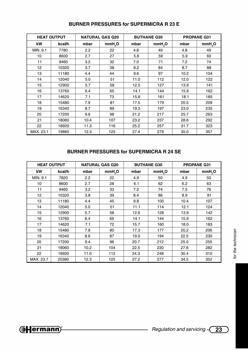
— wait for at least 10 seconds and check that the pres-sure corresponds to the MAX value indicated in the“BURNER PRESSURES” table of the specific model;
— extract one of the connectors [4] that supply the modu-lation coil; verify that the measured pressure corre-sponds to the MIN value indicated in the “BURNERPRESSURES” table of the specific model;
— reinsert the connector [4];
— if it is necessary to adjust the regulation, proceed as it follows, referring to the figure:
• take off the protection cap [C];
• adjust MAX pressure acting on the nut [B] (10 mm). Turn clockwise to increase pressure,counterclockwise to decrease pressure;
• extract again one of the connectors [4];
• adjust MIN pressure acting on the screw [A] (with a 4 mm screwdriver), paying attentionnot to contemporarily move the nut [B]. Turn clockwise to increase pressure,counterclockwise to decrease pressure;
• reinsert the connector [4] and check that MAX pressure is not changed;
• mount the cap [C];
Important: lock the adjustment device after any setting operation.
— For the “SE” models reinsert the tube in the “Vent” [3] of the gas valve. ATTENTION:after thisoperation, the value measured by the manometer could decrease due to pressure compensation.This fact is normal and does not require any change of the regulation;
— Screw the pressure tapping point screw for gas outlet [1] and verify that there is no gas leak.
— To switch off the burner, turn the Main Selector to the “0” position.
GAS VALVE
1 = Pressure tapping pointfor gas outlet
2 = Pressure tapping pointfor gas inlet
3 = Vent (mod. SE)
1
2
3 4
C
B
A
892_R
00

22 Regulation and servicing
for
the
tech
nici
an
Slow opening regulationTo adjust the slow opening, proceed as follows:
— switch off the boiler;
— release the screws [1] (see figure) and remove the back closing of the control panel;
REMARK: you will have 8 seconds for the regulation of the slow opening pressure, and after these8 seconds the pressure of the burner increases to the highest value. To increase this period oftime to 30 seconds, turn the trimmer P1 MAX.R. completely in anticlockwise sense (it will benecessary to regulate consequently the Max Heating Power).
— turn the boiler thermostat fully to right (maximum) and set room thermostat (if installed) to atemperature higher than room temperature;
— turn the Main Selector to Winter position: the burner will turn on allowing to check thepressure of slow opening. In case the values are different from:
Nat. gas: mod. 23 E: 3,5 mbar (36 mm w.g.) – mod. 24 SE: 7 mbar (71 mm w.g.)
L.P.G.: mod. 23 E: 8 mbar (82 mm w.g.) – mod. 24 SE: 14 mbar (143 mm w.g.)
turn the trimmer P4 RLA (in clockwise sense to increase the pressure and in anticlockwisesense to decrease the pressure) till the achievement of the correct value.
Regulation of MAX heating powerThe maximum heating output must be set in accordance with the system requirements (stated inthe project). The gas pressure values related to the different outputs are indicated in the table“BURNER PRESSURES”. To adjust the burner pressure proceed as follows referring to the figure:
— Remove the back closing of the control panel releasing the screws [1] (see figure).
— Set Main Selector to Winter position and adjust the eventual room thermostat to a tempe-rature value higher than the present one.
— When the burner is turned on (wait the end of the climbing ramp which lasts about 1 minute)check the value of the maximum gas pressure through the pressure gauge.
— Adjust pressure turning round the potentiometer P1 MAX. R. until reaching the required value.
— Close the control panel.
1
852R
00
51
51
C3C3
T1T1
R56
R56
MAX.R.MAX.R.
RLARLA
49
49
50
50
M12M12
P2P2
J24
J24R
28
R28
C5C5
FA1FA1
J7J7
C7C7
J17J17
IC2IC2
J19
J19
J20
J20
C4C4
SAN.SAN.
D6
D6
J5
J5 D5
D5
D4
D4
D3
D3
LL
M5M5
NN
TR1TR1
M10M10 J3J3 RL1RL1 RL2RL2 J6
J6
R26R26
R27R27
21
21
P3P3
P1P1
19
19
20
20
16
16
17
17
18
18
D7D7
M6M6
P4P4
52
52
J22
J22
J25
J25
22
22
11
SW3SW3
J21J21
R49R49
J16J16
J18J18
R33
R33
RIS.RIS.
M8M8
SW2SW2
3030
3131
RS1RS13232
3333
3535
3434
3737
R8R8
3636
J9
J9
SW1SW1
J10
J10
J14
J14
J13
J13
J12
J12
J23J23
66
OFFOFF
ONON
39
39
J4J4
40
40
J8J8
R25R25
J15J15
J11J11
77
J1J1
J2
J2
PTC1PTC1
2929
11
C2
C2
M1M1 3322 44
C1
C1
F1F188 99 1010
VDR1
VDR1
M2M2
D1
D1
D2
D2
R1
R1
R2
R2
55 66
23Regulation and servicing
for
the
tech
nici
an
BURNER PRESSURES for SUPERMICRA R 23 E
TUPTUOTAEH 02GSAGLARUTAN 03GENAHTUB 13GENAPORP
Wk h/lack rabm Hmm 2O rabm Hmm 2O rabm Hmm 2O
1.9.NIM 0877 2.2 22 8.4 94 8.4 94
01 0068 7.2 72 8.5 95 9.5 06
11 0649 2.3 23 0.7 17 2.7 47
21 02301 7.3 83 2.8 48 7.8 88
31 08111 4.4 44 6.9 79 2.01 401
41 04021 0.5 15 0.11 211 0.21 221
51 00921 7.5 85 5.21 721 9.31 141
61 06731 4.6 56 1.41 441 9.51 261
71 02641 1.7 37 8.51 161 1.81 581
81 08451 9.7 18 5.71 971 5.02 902
91 04361 7.8 98 3.91 791 0.32 532
02 00271 6.9 89 2.12 712 7.52 362
12 06081 4.01 701 2.32 732 6.82 292
22 02981 3.11 611 2.52 752 7.13 323
1.32.XAM 06891 3.21 521 4.72 972 0.53 753
BURNER PRESSURES for SUPERMICRA R 24 SE
TUPTUOTAEH 02GSAGLARUTAN 03GENAHTUB 13GENAPORP
Wk h/lack rabm Hmm 2O rabm Hmm 2O rabm Hmm 2O
1.9.NIM 0287 2.2 22 9.4 05 9.4 05
01 0068 7.2 82 1.6 26 2.6 36
11 0649 2.3 33 2.7 47 5.7 67
21 02301 8.3 93 4.8 68 9.8 19
31 08111 4.4 54 8.9 001 4.01 701
41 04021 0.5 15 1.11 411 1.21 421
51 00921 7.5 85 6.21 821 9.31 241
61 06731 4.6 56 1.41 441 9.51 261
71 02641 1.7 27 7.51 061 0.81 381
81 08451 8.7 08 3.71 771 2.02 602
91 04361 6.8 78 0.91 491 5.22 032
02 00271 4.9 69 7.02 212 0.52 552
12 06081 2.01 401 5.22 032 6.72 282
22 02981 0.11 211 3.42 842 4.03 013
7.32.XAM 08302 3.21 521 2.72 772 5.43 253

24 Regulation and servicing
for
the
tech
nici
an
Changing Gas typeATTENTION: the operations described below must be carried out only by qualifiedpersonnel [authorized from HERMANN Ltd].
For gas conversion, use the nozzles supplied by boiler manufacturer only.
Using LPG, it is absolutely necessary to install a pressure reducer upstream the boiler.
1. Disconnect the boiler from the electrical supply.
2. Remove the cover of the control panel and move the first microswitch of SW3 (on the right) inthe position suitable for the gas available:
MET (OFF) for Natural Gas (G20),
GPL (ON) for Butane (G30) or Propane (G31)
3. Check that pressure and gas input are enough toguarantee the correct functioning of the appliance.
4. On “SE” models, open sealed combustion chamber.
5. Remove pipe between gas valve and injectors bar.
6. Remove injectors bar and replace the nozzles with theones suitable for the available gas type, using a 7 mm.spanner (see figure “BURNER”). Reassemble injectorsbar and pipe, replacing gaskets. Check, with burner ON,that there are no gas leaks. On “SE” models, close sealedcombustion chamber;
7. Check, with burner ON, that there are no gas leaks andthat the pressure upstream the boiler is:
Natural gas: min.17 – max. 25 mbar
Buthane: min. 25 – max 35 mbar
Propane: min. 25 – max 37 mbar
8. Repeat the following regulations: gas valve MAX-MIN pressure regulation, Slow Opening andMax Heating Output, carefully following the instructions described in the previous pages.
9. Check that there are no gas leaks.
10. apply the sticker indicating the type of gas (supplied with the kit) on the suitable area on “WARN-ING” label inside the boiler.
BURNER
LEDOMrebmuNselzzonfo
rofØselzzoN02GSAGLARUTAN
)mm001/1(
rofØselzzoN13G/03G.G.P.L
)mm001/1(E32RARCIMREPUS 31 021 57
ES42RARCIMREPUS 31 021 57
1
SW3
ON
MET
GPL
853R
00
51
51
C3C3
T1T1
R56
R56
MAX.R.MAX.R.
RLARLA
49
49
50
50
M12M12
P2P2
J24
J24R
28
R28
C5C5
FA1FA1
J7J7
C7C7
J17J17
IC2IC2
J19
J19
J20
J20
C4C4
SAN.SAN.
D6
D6
J5
J5 D5
D5
D4
D4
D3
D3
LL
M5M5
NN
TR1TR1
M10M10 J3J3 RL1RL1 RL2RL2 J6
J6
R26R26
R27R27
21
21
P3P3
P1P1
19
19
20
20
16
16
17
17
18
18
D7D7
M6M6
P4P4
52
52
J22
J22
J25
J25
22
22
11
SW3SW3
J21J21
R49R49
J16J16
J18J18
R33
R33
RIS.RIS.
M8M8
SW2SW2
3030
3131
RS1RS13232
3333
3535
3434
3737
R8R8
3636
J9
J9
SW1SW1
J10
J10
J14
J14
J13
J13
J12
J12
J23J23
66
OFFOFF
ONON
39
39
J4J4
40
40
J8J8
R25R25
J15J15
J11J11
77
J1J1
J2
J2
PTC1PTC1
2929
11
C2
C2
M1M1 3322 44
C1
C1
F1F188 99 1010
VDR1
VDR1
M2M2
D1
D1
D2
D2
R1
R1
R2
R2
55 66

25Regulation and servicing
for
the
tech
nici
an
Combustion checkThe boiler has a “CHIMNEYSWEEPER” function which draws the ignition of the burner to thehighest power (not modulated) without working on the room thermostat or on the flow of hot water.
— Arrange the instruments for the combustion check;
— bring and keep the Main Selector in the position Chimneysweeper for at least 3 seconds,then release the selector. The green lamp flashes rapidly and the burner ignites at the maximumoutput, for a period sufficient to make the cheking and the measurements. The produced heat iscarried off by the heating system;
— to turn off the burner, turn the Main Selector in the central (0) position. The green lamp flashesslowly.
REMARK: the burner will turn off automatically at the achievement of the system highest tempera-ture and, however, after 15 minutes.
Hydraulic sectionPUMP’S SPEED
The pump has a selector which allows to reduce the speed, so as to reduce the noise produced bythe too rapid circulation of the liquids in too small heating systems.
III = Maximum Speed (Firm Set up)
II = Medium Speed
I = Minimum Speed
772R01

26 Regulation and servicing
for
the
tech
nici
an
Electronical regulationPOSSIBLE REGULATIONS ON THE MAIN P.C.B.
The “SUPERMICRA R” models are equipped with a Microprocessor P.C.B., with an array of 6microswitches (SW3 / 1÷6) which allow to make personalizing actions for the boiler’s functioning.The firm arrangements are underlined.
Remark: on some cases there may be 8 microswithes instead of 6 (SW3 / 1÷8). If so, microswitches7 and 8 (shown shadowed in the picture) must be set OFF.
Disconnect the power supply before approaching the microswitches. Restore the powersupply only after you have closed the back cover of the control panel.
Moreover, the changes of the microswitches haven’t effect until the boiler is electricallyconnected.
SW3 / 1 – Natural gas Functioning = OFF. LPG Functioning = ON. The firm arrangement dependson the gas type arranged for the boiler. For the GAS TYPE Changing it is necessary to followthe complete instructions described in the previous paragraph “Changing Gas type”.
SW3 / 2 – In SUPERMICRA R Boilers it must be OFF.
SW3 / 3 – It determines the delay of 3 Minutes, before the new ignition after the overcoming of theheating set temperature. OFF = Delay ON (for normal systems or radiators); ON = Delay OFF(for fan coil systems).
SW3 / 4 – This setting is not used in Supermicra R (heating only) models and it must be left in OFFposition.
SW3 / 5 and 6 – Pump Functioning Way in Heating System:
5 OFF – 6 OFF: intermittent for normal applications (with or without delay, see SW3/3)
5 OFF – 6 ON: always turned off (with outside circulators)
5 ON – 6 Unimportant (OFF or ON): always on (for high thermic Inertia systems)
854_
OF
F_R
00
ON ON
OFFSW3
128 7 6 5 4 3
51
51
C3C3
T1T1
R56
R56
MAX.R.MAX.R.
RLARLA
49
49
50
50
M12M12
P2P2
J24
J24R
28
R28
C5C5
FA1FA1
J7J7
C7C7
J17J17
IC2IC2
J19
J19
J20
J20
C4C4
SAN.SAN.
D6
D6
J5
J5 D5
D5
D4
D4
D3
D3
LL
M5M5
NN
TR1TR1
M10M10 J3J3 RL1RL1 RL2RL2 J6
J6
R26R26
R27R27
21
21
P3P3
P1P1
19
19
20
20
16
16
17
17
18
18
D7D7
M6M6
P4P4
52
52
J22
J22
J25
J25
22
22
11
SW3SW3
J21J21
R49R49
J16J16
J18J18
R33
R33
RIS.RIS.
M8M8
SW2SW2
3030
3131
RS1RS13232
3333
3535
3434
3737
R8R8
3636
J9
J9
SW1SW1
J10
J10
J14
J14
J13
J13
J12
J12
J23J23
66
OFFOFF
ONON
39
39
J4J4
40
40
J8J8
R25R25
J15J15
J11J11
77
J1J1
J2
J2
PTC1PTC1
2929
11
C2
C2
M1M1 3322 44
C1
C1
F1F188 99 1010
VDR1
VDR1
M2M2
D1
D1
D2
D2
R1
R1
R2
R2
55 66

27Regulation and servicing
for
the
tech
nici
an
Warnings for servicingAll servicing operations and gas conversions MUST BE CARRIED OUT BY QUALIFIEDTECHNICIANS, in accordance with the Law n°46 dtd. 05 March 1990 and with the rulesUNI-CIG 7129/01 and 7131/99 and revisions. Moreover, in accordance with art.11 section4 D.P.R. 412/93 and revisions, SERVICING operations must be carried out, at leastonce a year, by [HERMANN?] AUTHORIZED SERVICING CENTRES, and must be writtenin the appliance booklet, as indicated by the laws UNI and CEI presently in force.
At the end of each heating period, it is necessary to call a qualified technician to check the boiler, inorder to keep the system perfectly efficient.
A careful servicing is always a guarantee of safety and saving.
Normally, it will be necessary to execute the following operations:
— Remove any possible oxidization from burners and electrodes;
— Clean heat exchangers and electrodes;
— Check integrity and stability of the ceramic fibre coverings in the combustion chamber andproceed eventually to substitution;
— Check boiler ignition, switching off and operation;
— Check water and gas connections tightness;
— Check gas consumption at the minimum and maximum output;
— Verify that safety devices are correctly working;
— Verify correct functioning of control and adjusting devices;
— Verify periodically good working and efficiency of the combustion product evacuation ductsand/or devices;
— In case of works or servicing of the structures placed near above mentioned ducts and /ordevices and their accessories, switch off the boiler;
— Do not leave any inflammable tanks and/or substances in the installation room;
— Do not clean the room where boiler is installed, while it is working.
— Clean casing with soapy water only. Do not clean casing, other painted or plastic surfaces withthinner.
— In any case of parts replacement, it is mandatory to use HERMANN original spare parts.
HERMANN declines any responsibility in case of non-original spare parts utilization.
Once all servicing operations have been carried out, it is mandatory to write a report for theuser, that should indicate state of the appliance, servicing interventions and eventual advicesand prescriptions.

28 Regulation and servicing
for
the
tech
nici
an
Components of the gas boilerSUPERMICRA R 23 E
1 Flue thermostat2 Safety thermostat for max. water temperature3 Expansion vessel4 Ignition electrode5 Gas valve6 Water supply valve7 Safety pressure switch for min. water pressure8 Sensor for temperature control9 Burner
10 Flame sense electrode11 Primary heat exchanger12 Automatic venting device13 Flue hood14 Drain valve15 Heating system safety valve
3 bar16 Pump
1
2
3
4
14
745R
01
11
9
10
8
12
13
1615567

29Regulation and servicing
for
the
tech
nici
an
Components of the gas boilerSUPERMICRA R 24 SE
1
2
3
4
15
746R
02
11
9
10
8
13
12
1716567
14
1 Flue pressure switch2 Safety thermostat for max. water temperature3 Expansion vessel4 Ignition electrode5 Gas valve6 Water supply valve7 Safety pressure switch for min. water pressure8 Sensor for temperature control9 Burner
10 Flame sense electrode11 Primary heat exchanger12 Automatic venting device13 Fan14 Sealed chamber15 Drain valve16 Heating system safety valve
3 bar17 Pump

30 Regulation and servicing
for
the
tech
nici
an
C PumpCA Ignition and flame control unitEA Ignition electrodeER Flame sense electrodeF1 Fuse (2 A)MOD Modulatore
PSA Low water pressure switch(contact NO closed = in pressure)
S NTC sensorTA Voltage-free Contact for Room Thermostat
or Cronothermostat(for trade) (safety extra low voltage SELV)
TF Flue thermostatTS Safety thermostat
Electric diagram forSUPERMICRA R 23 E
EVZ1/2/3… Electrovalvezone 1/2/3…
AUX1/2/3… Auxiliarycontact forEVZ1/2/3…
TAZ1/2/3… Roomthermostatfor zone1/2/3…
Coloursabbreviations:BK Black
BN Brown
BU Blue
GN Green
GNYE Green-Yellow
GY Grey
OG Orange
RD Red
VT Violet
WH White
31Regulation and servicing
for
the
tech
nici
an
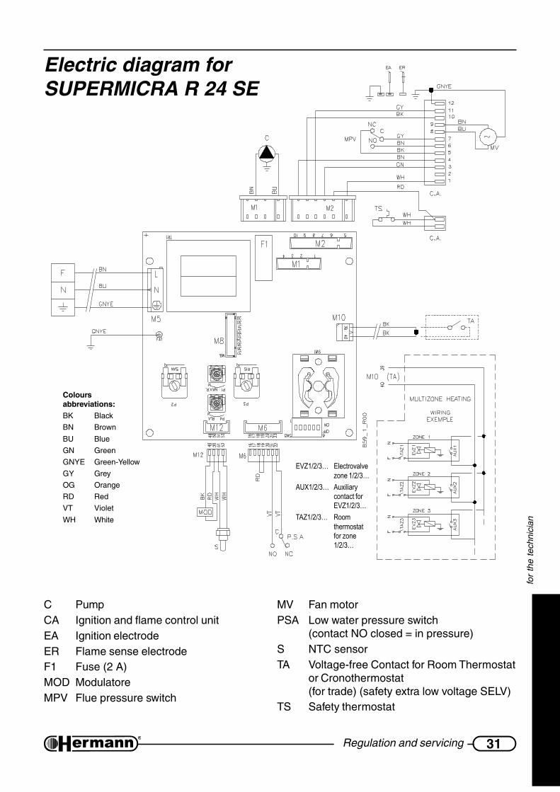
Electric diagram forSUPERMICRA R 24 SE
C PumpCA Ignition and flame control unitEA Ignition electrodeER Flame sense electrodeF1 Fuse (2 A)MOD ModulatoreMPV Flue pressure switch
MV Fan motorPSA Low water pressure switch
(contact NO closed = in pressure)S NTC sensorTA Voltage-free Contact for Room Thermostat
or Cronothermostat(for trade) (safety extra low voltage SELV)
TS Safety thermostat
Coloursabbreviations:BK Black
BN Brown
BU Blue
GN Green
GNYE Green-Yellow
GY Grey
OG Orange
RD Red
VT Violet
WH White
EVZ1/2/3… Electrovalvezone 1/2/3…
AUX1/2/3… Auxiliarycontact forEVZ1/2/3…
TAZ1/2/3… Roomthermostatfor zone1/2/3…
32 User instructions
for
the
user
USER INSTRUCTIONS
Warnings for first starting upThe first starting up must be done by a professionally qualified staff (for example theSERVICE CENTERS authorized by HERMANN).
Gas conversion from a specific gas (natural gas or LPG) to another gas, can be made also whenthe gas boiler is already installed, but only by a qualified technician. The technician will check that:
a) the label technical data of the gas boiler correspond to those of the gas, water and electricalsupply lines;
b) the main burner regulation is compatible with the gas boiler output;
c) the chimney works correctly, expelling the combustion products;
d) the air supply and the combustion products evacuation work correctly, in accordance with therequirements in force;
e) the conditions for a correct ventilation are guaranteed, also when the gas boiler is locatedinside a furniture.
Useful advicesWARNING for “E” models: The boiler is fitted with a safety thermostat for chimneydraught, operating in case of combustion products return in the installation room.This device must be always in function, because a combustion products return cancause chronic or acute intoxications with danger of death. If the thermostat must bereplaced, use the original spare part only. In case of repeated interventions of thedevice, check that the Flue Products Outlet System is efficient and made accordingto the laws in force (see examples in page 14).
WARNING for “SE” models: The boiler is fitted with a safety flue pressure switch. Thisdevice must be always in function. In case of repeated interventions, call a qualifiedtechnician. If the pressure switch must be replaced, use the original spare part only. Incase of repeated interventions of the device, check that the Air Flue Products Inlet/Outlet System is efficient and made according to the laws in force (see examples inpage 15).
INSTALLATION AND SERVICING
All installation, servicing and gas conversion operations MUST BE CARRIED OUT BY QUALIFIEDTECHNICIANS authorized by Law n. 46 dtd March 5th, 1990 and in accordance with UNI-CIG 7129/01 and 7131/99 requirements and revisions.
Moreover, in accordance with art.11 section 4 of DPR 412/93 and revisions, boiler MAINTENANCEoperations must be made at least once a year and following manufacturer’s specifications and UNIand CEI rules in force.

33User instructions
for
the
user
APPLIANCE BOOKLET OR CENTRAL PLANT BOOKLET
All appliances, even those installed before August 1st, 1994, must have an appliance booklet (foroutputs less or equal 35 kW) or a central plant booklet (for outputs more than 35 kW). All ordinaryand special servicing operations and combustion checkings must be written on the booklet, togetherwith the name of the person responsible for servicing.
COMBUSTION CHECKING
Combustion checking is made with a control of the boiler efficiency; this checking must be carriedout only by a person with the requirements of the Law 46/90. Boilers that, after the checking, willhave efficiency rates lower than the ones required and not changeable with suitable adjustments,must be replaced.
BOILER OPERATION AND SERVICING
The user (owner or tenant of the flat where the boiler is installed) or the administrator of the block offlats (in case of a central heating system) are responsible for the appliance operation and servicing;they can both transfer the responsibility of the servicing and eventually of the operation to anotherperson, which must have the requirements indicated by the Law 46/90. Even if the user or theadministrator decide to assume personally this responsibility, ordinary servicing of the warm airheater and combustion checkings must be carried out by a qualified technician.
WarningsIn case of gas smell:
a) do not press electrical switches, use the telephone or other objects that can provokesparks;
b) open immediately the windows and the doors in order to cleanse the room air;
c) close the gas supply taps;
d) call a qualified technician.
Do not obstruct the ventilation openings of the gas boiler room, in order to avoidpossible dangerous situations as the creation of poisonous or explosive mixtures.
When the boiler is off for a long period see the Paragraph “Inactivity of the Boiler” forthe necessary precautions about the electrical supply, the gas supply and the protectionagainst freezing.

34 User instructions
for
the
user
Boiler controlsTo have the access to the boiler controls it is sufficient to push onthe lower part of the panel, as shown in the figure.
In addition to the controls in the front panel, we remind you that theboiler must be equipped, during the installation process, with anexternal general switch which totally disconnects the boiler fromthe electrical supply.
Instructions for boiler ignition,functioning and turning offTO START THE BOILER
Open the gas tap and turn on the external general switch. The green lamp [1] flashes to show thatthe boiler is supplied but not on (in stand-by). Turn the Main Selector [2] in Winter position. Thegreen lamp [1] will turn constantly on, to show that the boiler is on.
ATTENTION: Do not activate the Chimneysweeper Function which is reserved for thetechnician and which forces the ignition of the burner (the green lamp flashes rapidly). If, bymistake, it should happen, bring immediately the main selector in the central position (0),wait until the green lamp flashes slowly, and then turn the selector in Winter position.
TO STOP THE BOILER (STAND-BY)
Turn the selector [2] in the central position (0).
If the boiler is off for a long period see the paragraph “INACTIVITY OF THE BOILER”for the necessary precautions about the electrical supply, gas supply and anti freezingprotection.
71
2 3
5
6
CONTROL PANEL

35User instructions
for
the
user
FUNCTIONING
Turn the selector [2] bringing it in the Winter position.
Regulate the Boiler Thermostat [3] at the desired temperature.
If a Room thermostat or a Cronothermostat is installed, the regulation of this last keeps the roomtemperature as that arranged (refer to the respective using instructions). In this case it is useful toregulate the boiler thermostat according to the outdoor seasonal climate, so as to allow thegaining of the desired temperature, but without excessive overheatings (consider that the radiatorsemit heat also after the turning off of the boiler).
If after the request the ignition does not take place, check that the red lamp [7] is not on: if it’s on,turn the selector [2] in the central Off/Unlock Position, wait until the red lamp [7] turns off, andthen bring it again in the Winter Position. See “Working and warning indicators” for moreinformation and useful advices to solve common problems.
Important:
The temperature in the boiler is shown by the thermometer [5] and the pressure is shown by theGauge [6].
Remark: If pressure falls down to 0.5 bar, boiler will stop (the red lamp turns on). To reset thesystem, proceed with system filling.
ROOM TEMPERATURE REGULATION
We want here to remind you that the room tempe-rature must be regulated through a roomthermostat with two temperature levels. Thisrequired by DPR 26 Agosto 1993 n°412 andrelevant changes.
SYSTEM FILLING
Make sure that the system pressure in a cold state isalways between 0.5÷1.5 bar (optimal pressure: 1÷1.5bar). If pressure is lower, open the filling valve (seefigure) till it reaches a maximum value of 1,5 bar; thisvalue is checked with the pressure gauge (item 6 inprevious Control Panel figure).
BOILER BOTTOM VIEW
FILLINGVALVE

36 User instructions
for
the
user
Working and warning indicatorsGREEN FUNCTIONING LAMP [1]
The green lamp can be off, flashing (slowly or rapidly) or on.
OFF: the boiler is electrically disconnected. In these conditions the boiler obviously doesn’twork. The Automatic Anti Freezing and Anti Blocking functions can’t be activated (useful duringlong period of inactivity). The external general switch could be off.
FLASHING (slowly): the boiler is electrically supplied but the Main Selector is in central position(0). The boiler will not turn on following the needs of heating, but the Anti Freezing and AntiBlocking Functions are on (this last can request the temporary ignition of the burner, then it isnecessary that the gas is open).
FLASHING (rapidly): the Chimneysweeper Function (which is reserved for the technician) is onby mistake.
Turn it off bringing the main selector in the central position (0) until the green lamp flashesslowly.
ON: the boiler is on and the main selector is in the WINTER Position. The boiler will turn onfollowing the needs of heating.
BOILER’S LOCK OUT RED LAMP [7]
The red lamp can be off, flashing and on.
OFF: the functioning of the boiler is correct.
FLASHING:
— The System Temperature Sensor (inside the boiler) is damaged. Call a QualifiedTechnician for repairing.
ON - it signals problems that can be normally solved by the user:
— The boiler has been just installed, or works have been made on the gas pipes.
It is normal that the boiler goes repeatedly in Lock Out when the Inlet Gas is mixedwith air. This impedes the correct ignition and then provokes the Lock out. In theconditions described above, it is necessary to repeat more times the ignition of theboiler turning the Main Selector in the Unlock Position until the red lamp turnsoff.
— The water pressure, shown by the gauge in the control panel, is not sufficient (0,5 baror lower).
Restore the correct pressure (optimal pressure: 1÷1,5 bar at cold system) openingthe inlet tap (the action is described before). Do not restore the pressure with hotsystem, because when the system gets cold the pressure decreases.
Consider that the pressure, in normal conditions, should not decrease. If this happens,there is probably a loss in the heating system. Sometimes the loss is so small that itdoesn’t leave evident signs, but with the progress of the time it can cause thedecreasing of the pressure.
Also the opening of the manual venting taps of radiators (intentional or unintentional)makes the pressure decrease. Check that this doesn’t happen.

37User instructions
for
the
user
— the boiler has an overheating and the Safety Thermostat has triggered;
Turn the Main Selector in the central Unlock Position until the red lamp turnsoff (or eventually for a longer period to make the boiler cool), then bring again theselector in the Winter position. If the Lock Out takes place again call the ServiceCentre.
— the burner hasn’t regularly switched on or the flame has suddenly turned off;incorrect combustion.
Restore the service turning the Main Selector in the Unlock Position until the redlamp turns off. In case of frequent Locks:
• Call a technician to check the combustion and verify that the burner is clean and ingood conditions;
In “SE” models with Sealed Combustion Chamber:
• Check that the Inlet/Outlet Ducts and the respective terminals are clean and in goodcondition, and that there are no leaks. During the Installation Process it is necessaryto respect the prescriptions included in the national and local regulations and laws, inaddition to the slopes and measurement included in the paragraphs “Chimneyconnections” and “Flue systems”.
Note for the TECHNICIAN: The burner flame is not detected by the Flame Control Unit becouse it has notturned on or it has suddendly turned off, or it has detached from the burner, because of an incorrectcombustion. This can be due, in exemple, to combustion product reflowing into inlet duct, leaks in inlet/outlet ducts or errors in sizing of ducts (ducts length above or below the allowed, and/or wrong use ofrestrictor on boiler’s outlet).
— “E” models with Natural Draught only: the device which signals the wrong FlueOutlet has intervened;
Exceptionally the cause can be a strong wind gust. Restore the service turning the MainSelector in the Unlock Position until the red lamp turns off. In case of frequent Locks:
• Check the efficiency of the Flue.
• Check that the outlet which communicates with the outdoor, compulsory accordingto the law, is not obstructed by pieces of furniture against the wall or by other objects.It is however normal that the outlet is realized behind a radiator. The outlet must be ofthe dimension prescribed by the law and must be cleaned inside: some types havean anti-insects net which could have been dirtied by dust or by spider’s webs. Call aQualified Technician when it is necessary.
71
2 3
5
6
CONTROL PANEL

38 User instructions
for
the
user
• If in the room where the boiler is installed there are mantelpieces, stoves, coal stovesor similar, fans for the Air Outlet, such as wall fans, aspiring cowls for cooking boardswith outlet pipe, let the technician check that the inlet is correctly OVERSIZED or thatthere are the ADDITIONAL Inlets as prescribed by the laws in force, because,otherwise, these devices interfere with the evacuation of the Boiler’s Flue.
Boiler inactivityThe effects of the periods of inactivity can be relevant in particular situations such as in flats usedonly for some months per year, most of all in cold places.
The user will have to decide to put the boiler in the SAFETY LOCK OUT state disconnecting all thesupplies, or to leave it in stand-by and use the Anti Freezing Function. In general it is better touse the SAFETY LOCK OUT. When there is the possibility of freezing it is convenient to chosebetween the advantages and the disadvantages of the SAFETY LOCK OUT and of the Stand By/Anti Freezing Way.
SAFETY LOCK OUT
— Turn off the general switch on the Electrical Supply Line of the Boiler;
— Close the Gas Tap;
When it is expected that the temperature is going to decrease under 0°C and the systemdoesn’t include the Anti Freezing Function, empty the heating system totally, or fill it with anAnti Freezing Solution.
Notice that if it had been necessary to restore the pressure (because of possible loss) in anheating system already filled with an Anti freezing solution, the concentration of the systemcould have decreased and it could not guarantee the Anti freezing Protection.
REMARK: the boiler is equipped with a system which protects the main components from theexceptional cases of LOCK OUT, due to the inactivity in presence of water and scale. The AntiLock out System can’t work during the Safety Lock Out Process, because of the lack of electricalsupply.
STAND-BY AND ANTI FREEZING/ANTI LOCK OUT FUNCTION
The boiler is equipped with an Anti freezing System which provides the ignition of the boiler wheneverthe temperature of the water in the heating circuit inside the boiler decreases under 5°C and whichprovides the turning off when the temperature reaches 30°C. In order to activate the Anti FreezingFunction:
• electrical power supply MUST be ON;
• boiler must be left in stand-by mode (main selector on 0, green lamp flashing);
• the gas must be left open;
• system pressure must be correct (1÷1.5 bar in a cold state, minimum 0.5 bar)
In case of lack of gas, the burner won’t turn on and the boiler will go in LOCK OUT state (red lampon or flashing). Nevertheless the pump will work, making the water circulate in the system andreducing in this way the possibility of freezing.
39User instructions
for
the
user
Moreover, the boiler in stand-by activates periodically the main internal components to prevent theexceptional cases of Lock out due to the inactivity in presence of water and scale. This happensalso if the boiler goes in Lock Out state (red lamp on or flashing).
Note: if you want to use the “room anti-freeze” function that is often available in common roomthermostats or chronothermostats, it is necessary to leave the boiler in Winter mode andNOT in stand-by.
Incidental not functioningTHE BURNER DOESN’T TURN ON
— If the room thermostat is installed, check that this is regulated with an higher temperature inrespect of that of the place where it is installed;
— check that there is electrical supply and that the Main Selector isn’t on 0 (stand-by) but onWINTER . The GREEN lamp must be constantly ON (see details in the paragraph “Workingand warning indicators”);
— if the Lock Out red lamp is on or flashing, see the paragraph “Working and warning indicators”;
— check on the gauge that the boiler pressure is correct (1÷1.5 bar in a cold state) or at least notlower than 0.5 bar.
— On SE models, the burner could not ignite because of an incorrect flue flow, or a fault to therelevant safety device. Ask the technician to check that inlet and outlet ducts are clean and in agood state. During installation, all laws and rules in force, and slopes and lenghts described in“Chimney connections” and “Flue systems”, must be respected. Ask the technician to check thecorrect functioning of the flue safety device (flue pressure switch) considering that a wrongslope of the outlet duct may make some condense to reflow to the boiler and damage the fluepressure switch.
Do not try to repair the gas boiler by yourself.
For any intervention on the electrical, hydraulic or gas circuit exclusively call a qualifiedtechnician.
The gas boilers must be fitted with original accessories only.
HERMANN Ltd. is not responsible for damages caused by the incorrect, wrong orunreasonable use of non-original materials.

40 User instructions
for
the
user
User warnings
— Check frequently water pressure on the hydrometer and verify that, when the system is cold,water pressure values are in line with the manufacturer instructions.
— If water pressure is frequently dropping down, call a qualified technician to repair possibleleakages in the system.
— If the boiler is off for a very long period, see the Paragraph “Inactivity of the Boiler” for thenecessary precautions about the electrical supply, the gas supply and the protection againstfreezing.
Do not touch the heated surfaces of the boiler, as the doors, the flue, the chimneypipe, etc., also after the boiler operation because, for a certain time, these surfacesare oveheated. Any contact with them can cause dangerous scalds. It is then forbiddento let children or inexperienced people be close to the boiler, during its operation.
— Do not expose the wall hung gas boiler to water vapours directly coming from gas cookers/hobs.
— Do not wet the gas boiler with water or other liquids sprinklings.
— Do not put any object on the gas boiler.
— The gas boiler utilization is forbidden to children and to inexperienced people.
— If the gas boiler is going to be definitively unused, call a qualified technician to carry out allrequired operations, checking in particular disconnection of gas, water and electrical supplies.
— Only on SUPERMICRA R 23 E models (natural draught): the installation of aspirators,fireplaces or similar appliances in the boiler room (and in adjacent rooms in case of indirectventilation), must be made in compliance with all specific safety rules and laws (for example byaugmenting the dimensions of ventilation openings), even in case of modifications or additions.
INSTRUCTIONS MANUAL
Make sure that the present manual is ALWAYS with the boiler, for any consultation of the user andservicing personnel.
HERMANN CONVENTIONAL GUARANTEE CONDITIONS
Hermann offers to the customer a particular and exclusive CONVENTIONAL GUARANTEE, whichis automatically activated asking the First Ignition to a Hermann Authorized Service Center. Theconditions of the HERMANN CONVENTIONAL GUARANTEE don’t prejudge nor invalidate therights indicated by the European Rule 1999/44/CE actuated with Italian Laws by the Decree 02Februar 2002 N°24 of which the User is the Owner.


10/2005 COD. 982160035 / REV. 008(UKENG)
HERMANN S.r.l. Via Salvo d’Acquisto 29010 Pontenure (PC)Tel. 0523/510341 Fax 0523/510359 E-MAIL : [email protected]
http://www.hermann.it
Hermann Ltd. declines any responsibility for eventual printing and/or transcription errors in thepresent manual.In order to constantly improve its products, Hermann Ltd. has the right to change features and datawritten in the present manual, at any time and without notice; therefore, this manual cannot beconsidered as a contract towards third parties.