Instructions - torrentee.com · GEK-95352 GE Industrial Systems Instructions Vertical Induction...
29
GEK-95352 GE Industrial Systems Instructions Vertical Induction Motors High Thrust Hollow and Solid-Shaft In-Line Solid-Shaft Frames 444-5011 NEMA Type P Base Weather Protected Type I and Type II
Transcript of Instructions - torrentee.com · GEK-95352 GE Industrial Systems Instructions Vertical Induction...

GEK-95352
�GE Industrial Systems
Instructions
Vertical Induction Motors
High ThrustHollow and Solid-ShaftIn-Line Solid-ShaftFrames 444-5011 NEMA Type P Base
Weather Protected Type I and Type II

GEK-95352
2
CONTENTS
Subject Page
Safety Precautions ...................................................................................................................................... 3Introduction................................................................................................................................................ 4Cross-Sectional Drawings..............................................................................................................24, 25, 26Receiving, Handling and Storage ................................................................................................................ 5 Unpacking ............................................................................................................................................... 5Installation.................................................................................................................................................. 6 Location and Mounting............................................................................................................................ 6 Pump and System Precautions.................................................................................................................. 6 Alignment of Solid-Shaft Motors ............................................................................................................. 7 Couplings for Hollow-Shaft Motors ......................................................................................................... 7 General ................................................................................................................................................. 7 Self-Release Couplings ......................................................................................................................... 7 Bolted Couplings .................................................................................................................................. 9 Non-Reverse Couplings ........................................................................................................................ 9 Power Supply and Connections .............................................................................................................. 10 Wiring and Grounding ........................................................................................................................ 10 Allowable Voltage and Frequency....................................................................................................... 10 Position of Conduit Box...................................................................................................................... 11 Lubrication ............................................................................................................................................ 11 Water Cooling ....................................................................................................................................... 11 General ............................................................................................................................................... 11 Oil Cooling Coil Connections ............................................................................................................. 11 Connection Fitting Drawing................................................................................................................ 12Operation.................................................................................................................................................. 12 Safety Warnings .................................................................................................................................... 12 Steps Prior to Initial Start-Up................................................................................................................. 12 Initial Start............................................................................................................................................. 14 Jogging and Repeat Starts ...................................................................................................................... 14Maintenance ............................................................................................................................................. 15 Safety Warning...................................................................................................................................... 15 General.................................................................................................................................................. 15 General Cleanliness ............................................................................................................................... 15 Coupling Maintenance ........................................................................................................................... 15 Relubrication ......................................................................................................................................... 16 Oil Viscosity (Table II) .......................................................................................................................... 17 End-Play Adjustment ............................................................................................................................. 17 General ............................................................................................................................................... 17 Ball Thrust Bearings ........................................................................................................................... 17 Spherical Roller Thrust Bearings......................................................................................................... 18 Bearing Replacement ............................................................................................................................. 19 Oil Cooling Coil Maintenance................................................................................................................ 19 Insulation and Windings ........................................................................................................................ 20 General ............................................................................................................................................... 20 Vacuum and Compressed Air Cleaning ............................................................................................... 21 Cleaning with Water and Detergent..................................................................................................... 21 Cleaning with Solvents ....................................................................................................................... 21 Revarnishing Windings ....................................................................................................................... 22Renewal Parts........................................................................................................................................... 22Trouble-Shooting Chart ............................................................................................................................ 23

GEK-95352
3
Safety Precautions
High voltage and rotating partscan cause serious or fatal in-jury. Installation, operationand maintenance of electricmachinery should be per-formed by qualified personnel.Familiarization with NEMA
Publication MG-2, Safety Standard for Construc-tion and Guide for Selection, Installation andUse of Electric Motors and Generators, the Na-tional Electrical Code and sound local practicesis recommended.
For equipment covered by this instruction book,it is important to observe safety precautions toprotect personnel from possible injury. Amongthe many considerations, personnel should beinstructed to:
• Avoid contact with energized circuits or ro-tating parts,
• Avoid by-passing or rendering inoperativeany safeguards or protective devices,
• Avoid use of automatic-reset thermal pro-tection where unexpected starting ofequipment might be hazardous to person-nel.
• Avoid contact with capacitors until safe dis-charge procedures have been followed.
• Be sure that the shaft key is fully captivebefore the motor is energized.
• Avoid extended exposure in close proximityto machinery with high noise levels.
• Use proper care and procedures in han-dling, lifting, installing, operating and main-taining the equipment.
• Do not lift anything but the motor with themotor lifting means.
Safe maintenance practices with qualified per-sonnel are imperative. Before starting mainte-nance procedures, be positive that:
• Equipment connected to the shaft will notcause mechanical rotation,
• Main machine windings and all accessorydevices associated with the work area aredisconnected from electrical power sources.
If a high potential insulation test is required,procedures and precautions outlined in NEMAStandards MG-1 and MG-2 should be followed.
Failure to properly ground the frame of the ma-chine can cause serious injury to personnel.Grounding should be in accordance with theNational Electrical Code and consistent withsound local practice.
These instructions do not purport to cover all of the details or variations in equipment nor to provide for every possiblecontingency to be met in connection with installation, operation or maintenance. Should further information be desired orshould particular problems arise which are not covered sufficiently for the purchaser’s purposes, the matter should be re-ferred to the General Electric Company.
1988, 1999 General Electric Company

GEK-95352
4
I. INTRODUCTION
General Electric high-thrust vertical mo-tors covered by these instructions arecarefully constructed of high-quality ma-terials and are designed to give long andtrouble-free service when properly in-stalled and maintained. These motors aregenerally used to drive pumps.
Both HOLLOW-SHAFT and SOLID-SHAFT motors are described in this in-struction book. Figure 1 shows a typicalhollow-shaft high-thrust motor. The solid-shaft construction is similar except thatthe top half-coupling is omitted, and themotor shaft extends out the bottom of themotor. See Figure 2. Solid-shaft high-thrust motors are not suitable for drivingloads that impose significant radial loadon the motor shaft; they should not, forexample, be used for belt-drive applica-tions.
Motors may be supplied with differentbearing arrangements for various externalthrust conditions imposed by the pump,such as different magnitudes of down-thrust and either momentary or continu-ous up-thrust. A typical high-thrust motorwith angular-contact ball bearings isshown in Figure l. This standard con-struction is for high continuous down-thrust and is suitable for momentary up-thrust equal to 30% of the rated down-thrust capacity of a high-thrust motor.NOTE THAT ANGULAR-CONTACTBEARINGS CAN ONLY CARRYTHRUST IN ONE DIRECTION.
Figure 3 shows a typical solid-shaft high-thrust construction (on right side) for ap-plications requiring continuous up-and-down thrust capability. In this type ofmotor, two or three angular-contact ballbearings are mounted in opposed mount-ing with one bearing oriented to carry up-
thrust and one or two oriented to carrydown-thrust. If greater down-thrust ca-pacity is required, motors may use one ortwo standard angular-contact ball bear-ings and one split-race bearing whichgives the capacity of two or three bear-ings down and one bearing up. This does,however, give more end-play than nor-mal.
IN-LINE motors (designed to be mountedon pumps which are directly in the pipe-line, and hence called IN-LINE motors)are also covered by this instruction book.These motors have two opposed-mountedangular-contact ball thrust bearings at thetop end of the motor so they can carryeither up or down thrust. The lower guidebearing is a radial-ball type and also car-ries any radial load imposed by the pump.IN-LINE motors are always of the solid-shaft type. This construction is shown onthe left side of Figure 3.
Spherical-roller bearings are sometimesused for applications requiring extra highdown-thrust capacity and/or extra bearinglife; these bearings may require water-cooling. See Figure 2. Motors withspherical-roller thrust bearings also re-quire certain minimum down-thrust dur-ing all continuous operation.
Since overloading greatly reduces bearinglife, the amount of thrust applied shouldnot exceed the recommended values.
This instruction book applies to motorswith either Weather-Protected I orWeather-Protected II enclosures as de-fined by NEMA. Both of these are “open"motors. (WP-II enclosure is not availablein 440 frame series.)
Weather-Protected I motor construction isshown in Figure 1 for 500 frame motorsand in Figure 3 for 440 frame motors.
GEK-95352
5
Weather-Protected II motor constructionis shown in Figure 2. This enclosure ischaracterized by additional protection atthe air inlet and outlet passages and bygaskets, drains, and other features tomake it suitable for use outdoors in severeclimates. Filters can be supplied for theair-inlet openings. When used, theyshould be cleaned periodically, sinceclogged filters restrict the amount ofcooling air and cause the motor to over-heat. Gages are sometimes used to meas-ure the pressure drop across the filter andthus indicate its condition. Filters shouldbe cleaned when the gage reads over 0.4”of water.
II. RECEIVING, HANDLING ANDSTORAGE
Each motor should be carefully examinedwhen received and a claim filed with thecarrier for any damage. The nearest officeof the General Electric Company may of-fer guidance.
The motor should be lifted bythe lugs provided. These lugsare intended for lifting the mo-tor only and must not be usedto lift any additional weight. Becareful not to touch overhead
equipment. Failure to observe this warningmay result in personal injury or death.
If the motor is not to be installed immedi-ately, it should be stored in a clean, drylocation. Precautions should be taken toprevent the entrance of moisture, dust, ordirt during storage and installation. Pre-cautions are taken by the factory to guardagainst corrosion. The machined parts areslushed to prevent rust during shipment.Examine the parts carefully for rust andmoisture, if the equipment is to be stored,and re-slush where necessary.
Motors are shipped without oil in thebearing reservoirs. An oil film remains on
the bearings, but if the storage period is toexceed three months, the reservoirsshould be filled. It is suggested that suchoil-filled motors be conspicuously taggedin order to prevent mishandling, whichwould cause oil spillage and subsequentdamage to the internal parts of the motor.When filling for storage, fill to the maxi-mum level shown on the gage or ap-proximately ½” over the mark showingthe standstill level. Before operating themotor, drain this oil and refill with freshoil.
See instructions under RELUBRI-CATION for oil recommendations.
During storage, windings should be pro-tected from excessive moisture absorptionby some safe and reliable method ofheating. Space heaters, if supplied, maybe used for this purpose. The temperatureof the windings should always be main-tained a few degrees above the tempera-ture of the surrounding air. It is recom-mended that motors in storage be in-spected, the windings meggered, and alog of pertinent data kept. Any significantdecrease in insulation resistance shouldbe investigated.
If a motor is to be in storage for over oneyear, it is recommended that competenttechnical inspection service be obtainedto ensure that the storage has been ade-quate and that the motor is suitable forservice. Contact your nearest GeneralElectric Sales office to arrange for in-spection service.
A. Unpacking
If the machine or machine parts havebeen exposed to low temperature, unpackit only after it has reached the temperatureof the room in which it will be unpackedor located; otherwise sweating will occur.
GEK-95352
6
III. INSTALLATION
Installation should be in accor-dance with the National Electri-cal Code and consistent withsound local practices. Couplingguards should be installed asneeded to protect against acci-
dental contact with moving parts. Machinesaccessible to personnel should be furtherguarded by screening, guard rails, or other suit-able enclosure to prevent anyone from comingin contact with the equipment. This is especiallyimportant for motors that are remotely or auto-matically controlled or have automatic re-setting overload relays, since such motors maystart unexpectedly. Failure to observe theseprecautions may result in injury or death to per-sonnel.
A. Location and Mounting
Allow enough space around the motor topermit free flow of ventilating air and tomaintain an ambient temperature not over40° C. Where a choice of locations is pos-sible, install the motor so that it will besubjected to the least amount of dirt, dust,liquids, or other harmful materials. Mountthe motor securely on a level, firm foun-dation, align accurately with the drivenequipment, and tighten mounting boltssecurely.
Weather-Protected Type I motors may beinstalled in indoor locations with rela-tively high moisture content or shelteredoutdoor locations in dry climates.
Weather-Protected Type II motors may beinstalled outdoors. Use filters in uncleanareas.
If ignitable dust or lint is pres-ent the surface temperature ofspace heaters, if supplied,should not exceed 80% of theignition temperature. Refer tospace heater nameplate or fac-
tory for information on surface temperature.Dust and-or lint should not be allowed to buildup around the surface of space heaters. Fail-ure to observe these precautions may result indamage to equipment, injury to personnel orboth.
A. Pump and System Precautions
Some precautions are necessary to assuresatisfactory operation of motors inpumping service. The packing gland inthe pump head should be kept in goodcondition so that the liquid being pumpedwill not be forced out along the shaft andenter the motor through the lower bearinghousing.
Motors driving pumps in pressure sys-tems where the pressure is maintainedafter shutdown should be protected fromover speeding by check valves, or non-reverse couplings.
Installation of the machinewhere hazardous, flammable, orcombustible vapors or dustspresent a possibility of explo-sion or fire should be in accor-dance with the National Electri-
cal Code, Articles 500-503, and consistent withsound local practices. Extreme care is requiredfor machines supplied with an explosion-proofor dust-ignition proof accessory device or con-duit box since any nicks or burrs in the sealingsurfaces during disassembly and reassemblymay destroy the explosion-proof or dust-ignition proof features. Failure to observethese precautions may result in damage to theequipment, injury to personnel, or both.

GEK-95352
7
The SYSTEM REED CRITICALFREQUENCY should be 25% above orbelow motor operating speed in order toavoid excessive vibration.
C. Alignment of Solid-Shaft Motors
Accurate mechanical lineup is essentialfor successful operation. Mechanical vi-bration and roughness when the motor isrunning may indicate poor alignment. Ingeneral, lineup by straight edge across,and feeler gages between coupling halvesis not sufficiently accurate. It is recom-mended that the lineup be checked withdial indicators. The space between cou-pling hubs should be maintained as rec-ommended by the coupling manufacturer.
D. Couplings for Hollow-ShaftMotors
1. General
Vertical hollow-shaft motors aredesigned for driving deep-well, tur-bine-type pumps and can beequipped with either self-release,bolted, or non-reverse couplings asdescribed in following sections.These couplings are located at thetop of the motor and allow pumpimpeller position to be adjusted eas-ily. The type of coupling is specifiedby the customer. Remove the topcap for access to the coupling.
Two slots are provided in the out-side rim of the coupling so that a barcan be inserted to keep the assemblyfrom turning while the adjustmentof pump impeller clearance is beingmade. A coupling bolt can bescrewed into one of the extra tappedholes in the top endshield to providea stop for the bar.
To prevent breakage, coupling boltsmust be tightened to torque valuesindicated below for bolted or non-reverse couplings
Bolt Size Torque1/2 90 lb-ft5/8 180 lb-ft3/4 320 lb-ft1 710 lb-ft
It shall be the installer’s re-sponsibility in all cases to as-certain that these torque valuesare used and maintained. Thisshall include those instances
when the coupling comes mounted in the mo-tor. Failure to comply may cause the couplingbolts to break, with resultant extensive damageto the equipment.
2. Self-Release Couplings
Should the motor accidentally berun in the reverse direction, thepump line-shaft joints may unscrew.The self-release coupling acts tolimit the amount of this unscrewing.In normal operation, torque from themotor is transmitted by the lowerhalf-coupling through the drivingpins to the upper half-coupling, andthen to the pump shaft. If reversaloccurs and the pump shaft starts tounscrew and lengthen, the upperhalf of the self-release coupling islifted up off of the driving pins, thusuncoupling the pump from the mo-tor. See Figure 1, where a self-release coupling is shown to the leftof the shaft center-line.
NOTE : THAT SELF-RELEASE COU-PLINGS CANNOT CARRY UP-THRUST
Proper functioning of a self-releasecoupling depends upon several fac-tors. The pump shaft adjusting nutmust be securely attached to the top

GEK-95352
8
half-coupling, and the top half-coupling must not bind on the lowerhalf. Otherwise, the adjusting nutlock-screw may break instead of thecoupling halves separating. Shouldthis happen, the motor would con-tinue to drive the pump line shaft,and the joints would continue to un-screw. Serious damage to both mo-tor and line shaft may result. Clear-ance between the coupling halvesshould be checked by placing thetop half-coupling in position prior toinstalling the motor. It should dropinto place, and rest solidly on thelower half-coupling, without forc-ing.
Proper alignment of the pump head-shaft within the motor hollow shaftis also important. After the couplingreleases it no longer holds the pumpshaft centered. If the alignment isnot good, the motor shaft which isstill rotating may rub the pump shaftwhich has stopped, and damage willresult.
A third requirement is that the dis-tance between the top of the pumpshaft and the inside of the top cap beat least enough to allow the top half-coupling, when it tries to release, toclear the pins before the shaft hitsthe cap. Check this clearance afterthe adjusting nut has been drawn upto its final position. To facilitatemaking the check, the motor outlineprint shows a maximum dimension"XH" from the top of the couplingto the top of the pump shaft. Ad-hering to this design limit will allowthe shaft and coupling to lift enoughto clear the pins and still leave asmall clearance between the shaftand cap. For standard motors, “XH”is as shown in Table 1.
Table 1
Frame Size XH444-449 4.38”
509-5011 4.88”
Depending upon the circumstancescausing reversal and upon whichline-shaft joint unscrews, there maybe enough energy stored in the ro-tating parts, at the time the couplingclears the pins, to cause the pumpshaft to continue to rise and strikethe top cap. However, if the aboveconditions are met, damage, even inthe most severe cases, should belimited to a broken cap.
It is intended that self-release cou-plings will be called upon to un-couple only infrequently.
NOTE: ANY TIME A SELF-RELEASECOUPLING UN-COUPLES, IT ISNECESSARY T0 REMOVE ALLPOWER AND MANUALLY RE-COUPLE.
Uncoupling is most frequentlycaused by application of single-phase power after a power supplydisturbance, while the motor is be-ing driven in the reverse directionby the pump; this single-phasepower causes the motor to take overand drive the pump in the reversedirection and the pump shaft jointswill then unscrew. To prevent this,select a motor starter which requiresa manual start after any stop (ratherthan allowing automatic re-start assoon as power is applied to thestarter), or incorporates a back-spintimer to keep power from beingautomatically reapplied to the motoruntil enough time has elapsed forwater back-flow through the pumpto stop and for the motor to com-pletely stop.

GEK-95352
9
Power supply phase-sequence rever-sal will also cause the motor to re-verse and unscrew the pump shaft,but this rarely occurs. An anti-phase-reversal relay can be incorpo-rated in the motor controller if de-sired.
To prevent uncoupling on initialstart-up, check motor rotation direc-tion before installing the upper half-coupling to be sure direction is cor-rect. To reverse direction of rota-tion, interchange any two powerleads.
2. Bolted Couplings
Bolted couplings allow up-thrustfrom the pump to be taken by themotor bearings. This type of cou-pling is similar to a self-releasecoupling except that the driving pinsare replaced by bolts, which shouldbe securely tightened to hold thetwo halves of the coupling solidlytogether so that torque is transmittedby face friction. See torque re-quirements. This type of couplingdoes not have the self-release fea-ture and allows reverse rotation.
See the self-release coupling shownto the left of the motor centerline inFigure 1, which is applicable tobolted couplings except that theheadless drive pins are replaced bybolts as explained above.
4. Non-Reverse Couplings
The non-reverse type of coupling, asshown to the right of the motorcenterline in Figure 1, is also abolted type, and, in addition, itkeeps the pump and motor from ro-tating in the reverse direction. Thus,it not only prevents the pump shaft
from unscrewing, but it also pre-vents damage from overspeedingand damage to water-lubricatedpump shaft bearings, when duringshutdown the residual water in thesystem drives the pump in the re-verse direction. This type of cou-pling also allows up-thrust from thepump to be carried by the motorbearings. Motor torque is transmit-ted to the pump shaft through thetwo halves of the coupling whichare bolted together. See requiredbolt torques.
The operation of a non-reverse cou-pling is explained as follows. Whenthe motor is started in the correct orforward direction, the ratchet pinsare lifted by the ratchet teeth, andare held up by centrifugal force andfriction when motor speed becomeshigh enough. When power is re-moved, the speed decreases, and thepins fall. At the instant of reversal, apin will catch on a ratchet tooth andprevent backward rotation. Thenumber of pins differ from thenumber of teeth to multiply thenumber of stopping positions.
A very rapid decrease in speed canresult in acceleration forces greatenough to prevent the pins fromdropping. This condition is furtheraggravated when the pins becomedirty, and their action sluggish. Ifthe time from shutdown (the instantthe “stop” button is pressed) to zerospeed is greater than two seconds,operation will be satisfactory.
To permit operation when stoppingtime is less than two seconds, thepins are spring-loaded. For thosecases involving cycling (frequentstarting and stopping) and stoppingtimes greater than two seconds, the

GEK-95352
10
springs may be removed to decreasewear on the ratchet plate.
Pins and springs are made of heat-treated stainless steel.
A complete non-reverse couplingconsists of a self-release couplingplus a non-reverse assembly, whichincludes pin carrier, pins, springs,pin retaining plate, and cap-screws.On motors covered by this instruc-tion book, the ratchet teeth are anintegral part of the endshield covercasting.
A self-release or a bolted couplingcan be converted to a non-reversecoupling without disturbing the ad-justment of the pump shaft nut. Thenon-reverse aAssembly will nor-mally be received as a unit. To as-semble it onto the motor, loosen the3 small capscrews that hold the pin-retaining plate so this plate can becentered during assembly. Next, re-move the drive-pins or bolts from thelower half-coupling. Then slide thenon-reverse assembly down over thetop half-coupling. Next insert thelong cap screws through the plate,pin carrier, and top coupling and intothe lower coupling. Tighten themsecurely so that torque will be trans-mitted by friction between the cou-pling faces rather than through thebolts. See TORQUE REQUIRE-MENTS. Finally tighten the 3 smallcapscrews to secure the pin-retainingplate.
The top half of the coupling shouldseat solidly on the lower half andthe pins should touch the bottom ofthe pockets between the teeth in theratchet. The clearance between thepin-carrier and the top of the ratchetteeth should be between 1/16 and1/8”.
When installing a non-reversecoupling do not use lubricant. Lu-brication will lower the coefficientof friction between pins and pin-carrier, and the pins may not stay upwhen motor reaches full speed.
Motors shipped from stock mayhave their top couplings and non-reverse assemblies packaged sepa-rately. They can be installed as de-scribed in previous paragraphs.
E. Power Supply Connections
1. Wiring and Grounding
Motor and control wiring, over-load protection, and groundingshould be in accordance withthe National Electrical Code andconsistent with sound localpractices. Failure to observe
these precautions may result in damage to theequipment, injury to personnel, or both.
Stator winding connections shouldbe made as shown on the connectiondiagram or in accordance with thewiring diagram attached to the in-side of the conduit box cover. For 3-lead motors no connection diagramis needed or supplied.
The motor frame may be groundedby attaching a ground strap from aknown ground point to the bronzegrounding bolt in the conduit box.
2. Allowable Voltage andFrequency
The power supply must agree withthe motor nameplate voltage andfrequency. Motors will operate (butwith characteristics somewhat dif-ferent from nameplate values) online voltages within + l0% of name-plate value or frequency within

GEK-95352
11
+ 5% and a combined variation notto exceed + 10%.
3. Position of the Conduit Box
When mounting conditions permitthe conduit box may be turned sothat entrance can be made upward,downward, or from either side.
F. Lubrication
Motors with oil-lubricated bearings areshipped without oil. Before starting themotor, fill each reservoir to the standstilllevel shown on the sight gage. Be carefulto keep dirt out of the lubricant and bear-ing housing.
Use only the oil specified on the lubrica-tion nameplate or the lubrication instruc-tion supplied with each motor. SeeRELUBRICATION, TABLE II andLUBE NAMEPLATE for oil grade andviscosity and further instructions.
If reservoirs have had oil in them duringstorage period, drain out this old oil wheninstalling the motor for operation.
G. Water Cooling
1. General
If a bearing requires auxiliary watercooling, the oil reservoir will beprovided with a cooling coil whoseends are brought out to fittings inthe end-shield wall (see Figure 2).
The lubrication nameplate or in-struction will specify the requiredwater flow and the maximum waterflow in gallons per minute. Ex-ceeding this maximum flow couldcause deterioration of the coolingcoil.
Whenever the motor is running,enough water should be circulatedthrough the coil to keep the steadyoil-bath temperature below 150° F(65°C).
The maximum pressure and maxi-mum temperature allowable forcooling water are also shown on thenameplate or instructions. Exceed-ing these values may damage thecoil or give insufficient cooling ofthe lubricating oil. Use only pure,clean water unless the motor wasspecifically ordered to have a coiland fittings of special material towithstand corrosive water. Standardcooling coils are made from type'K" copper tubing with wall thick-ness of 0.050”.
When the motor is shut down duringfreezing weather, blow any remain-ing water out of the coil.
2. Oil Cooling Coil Connection
As indicated above, a cooling coil isused to keep oil in the bearing res-ervoir cool. Water at pressures ashigh as 100 PSI is circulatedthrough the coil. It is imperative,there for, that all joints be tight andthat there be no leaks. A pin-holeleak will quickly allow enough wa-ter to overflow into interior of motorand cause motor failure.
Motors covered by this instructionbook are furnished with inlet andoutlet connection fittings designedto prevent inadvertent loosening ofinternal joints or undue stress on theinternal piping when external watersupply pipes are connected to themotor.

GEK-95352
12
See Figure 4 and the followingparagraphs for further instructions.Also see maintenance instructions.
To make water connections, simplyremove the pipe plugs (furnished forshipping) from brass fittings B andmake connection to female pipe-tapped hole in accordance with ap-plicable codes and good practice.TIGHTEN CONNECTIONS SE-SECURELY BUT NOT EXCES-SIVELY. It is recommended thatthe upper fitting be used for inletand lower fitting for drain.
DO NOT LOOSEN SCREWS F ORREMOVE PART B WHENCONNECTING WATER SUPPLYTO MOTOR: PART B MUST BEFULLY SEATED AGAINSTPART A TO COMPRESS THEWATER/OIL SEALING O-RING.Part A is screwed into the endshieldwall and locked with set-screws E --when making water connectioncheck part A to be sure it is tightand there are no oil leaks around it.Since there is no solid connectionbetween parts A and C, inadvertentloosening of internal connections isminimized.
COOLING COIL CONNECTION FITTINGS
IV. OPERATION
Before energizing the motor forthe first time or after an ex-tended shutdown, it is advis-able to check insulation resis-tance, power supply and me-chanical freedom of the motor.
If the motor has been stored in a damp loca-tion, dry it out thoroughly before operating.
Be sure that the motor is notrunning and the power supplyis disconnected before workingon motor.
A. Steps Prior to Initial Start-Up orAfter a Long Idle Period
1. Check insulation resistance asindicated in the caution above.
Before measuring insulationresistance the machine must beat standstill and all windings tobe tested must be electricallyconnected to the frame and toground for a time sufficient to
remove all residual electrostatic charge. Failureto observe these precautions may result in in-jury to personnel.
In accordance with established stan-dards, the recommended minimuminsulation resistance for the statorwinding is as follows:
VSRS = + 1
1000
Where RS is the recommendedminimum insulation resistance inmegohms at 40º C of the entire sta-tor winding obtained by applying di-rect potential to the entire windingfor one minute, and VS is rated ma-chine voltage.

GEK-95352
13
NOTE SEE IEEE RECOMMENDEDPRACTICE FOR TESTING INSU-LATION RESISTANCE OF ROTATINGMACHINES, PUBLICATION NO. 43,FOR MORE COMPLETE INFOR-MATION.
If the insulation resistance is lowerthan this value, it may be wet and itis advisable to eliminate the mois-ture in one of the following ways:
a. Dry the stator in an air circulatingoven with the air surrounding the part at95ºC to 115ºC until the stator has beenabove 90º C for at least four hours. Thenthe air temperature may be raised to135ºC to 1 15ºC. Continue to heat untilthe insulation resistance is constant for aone-half hour period.
b. Enclose the motor with canvas orsimilar covering, leaving a hole at the topfor moisture to escape. Insert heatingunits or lamps and leave them on until theinsulation resistance is constant for one-half hour period. Be careful not to getheating units so close to the winding thatthey cause localized damage.
c. With the rotor locked and using ap-proximately 10% of rated voltage, pass acurrent through the stator windings. In-crease the current gradually until the tem-perature reaches 90ºC . Do not exceedthis temperature. Maintain a temperatureof 90ºC until the insulation resistance be-comes constant for a one-half hour pe-riod.
2. Check bearing oil reservoirs tobe sure they have been filled to theproper level with fresh oil. SeeRELUBRICATION, TABLE II,
and LUBE NAMEPLATE on motorfor oil grade and viscosity and fur-ther instructions. Be sure filler capsand drain plugs are securely tight-ened.
3. Whenever possible, examinethe interior of the machine for looseobjects or debris which may haveaccumulated, and remove any for-eign material.
4. If possible, turn the rotor byhand to be sure that it rotates freely.
5. Check all connections with theconnection diagram. Check all ac-cessible factory-made connectionsfor tightness to make sure none hasbecome loose during shipment.
6. Check water-cooling connec-tions, flow, and temperature.
7. If possible leave motor un-coupled (or uncouple it) for initialoperation so that motor vibration,noise, current and bearings can bechecked uncoupled before they aremasked by the pump. To run a VHSmotor uncoupled, it is recommendedthat the pump head-shaft be re-moved. If this cannot be done re-move the upper half-coupling andbe sure the pump shaft is well cen-tered in the motor shaft so it will notrub. IF THIS IS DONE, ROTATEMOTOR BY HAND TO BE SURETHERE IS NO INTERFERENCEBETWEEN SHAFTS. Do not try torun motor uncoupled by just re-moving gib-key.
8. When the driven machine islikely to be damaged by the wrongdirection of rotation, it is imperativeto uncouple the motor from its loadduring the initial start and make cer-

GEK-95352
14
tain that it rotates in the correct di-rection. If it is necessary to changerotation, interchange any two lineleads. For multispeed motors checkeach speed independently. On VHSmotors do this before installingpump head-shaft and upper half-coupling.
Some motors are designed for unidi-rectional rotation. Rotation of thesemotors must be in accordance withthe rotation indicated on the name-plate and the outline furnished withthe equipment.
B. Initial Start
1. After inspecting the machinecarefully as outlined above, makethe initial start by following theregular sequence of starting opera-tions in the control instructions.
2. Run the motor uncoupled ini-tially, if possible, checking for ab-normal noise, vibration or bearingtemperatures, and for current andvoltage balance. Then check motoroperation under load for an initialperiod of at least one hour to ob-serve whether any unusual noise orhotspots develop.
3. In the event of excessive vi-bration or unusual noise, remove allpower and disconnect the machinefrom the load and check themounting and alignment.
4. Space heaters should be de-energized during motor operation.
5. Check line voltage on all 3phases to be sure it is balanced and
within 10% of motor rated voltagewith motor drawing load current.
6. Check the operating currentagainst the nameplate value. Do notexceed the value of nameplate am-peres X service factor (if any) understeady continuous load. Also checkto be sure that current in all threelines is balanced.
C. Jogging and Repeated Starts
Repeated starts and/or jogs ofinduction motors greatly reducethe life of the winding insula-tion. The heat produced byeach acceleration or jog ismuch more than that dissipated
by the motor at full load. If it is necessary to re-peatedly start or jog a motor, it is advisable tocheck the application with the local GeneralElectric sales office.
Check motor heating but do not de-pend on your hand to determinetemperature. Use the temperaturedetectors furnished in the motor ifthere are any (eg., RTD’s or thermo-couples), or use a thermometer. Ifthere is any doubt about the safe op-erating temperature, take the tem-perature of the part in question andconfer with the nearest sales officeof the General Electric company.Give full details, including allnameplate information.
Overheating of the motor may becaused by improper ventilation, ex-cessive ambient temperature, dirtyconditions, excessive current due tooverload, unbalanced a-c voltage, or(if a variable speed controller isused) harmonics in power suppliedto the motor.

GEK-95352
15
V. MAINTENANCE
Before initiating maintenanceprocedures, disconnect allpower sources to the motor andaccessories. For machinesequipped with surge capacitorsdo not handle capacitor until it
is discharged by a conductor simultaneouslytouching all terminals and leads, includingground. This discharge conductor should beinsulated for handling.
Replace all normal grounding connections priorto operating.
Failure to observe these precautions may resultin injury to personnel.
A. General
Inspect the motor at regular intervals, asdetermined by service conditions. Keepthe motor clean and the ventilation open-ings clear.
In addition to a daily observation of theoverall condition, it is recommended thata regular inspection routine be set up tocheck periodically the following items:
1. General Cleanliness
2. Insulation and Windings
3. Lubrication and Bearings
4. Coupling Bolt Tightness
B. General Cleanliness
The interior and exterior of the machineshould be kept free from dirt, oil, greaseand conducting dust. Oily vapor, debris,or dust may build up and block off venti-lation. Any of these contaminants canlead to early motor failure. Motors shouldbe disassembled and thoroughly cleanedperiodically as needed.
Motors may be blown out with dry, com-pressed air of moderate pressure. How-ever, cleaning by suction is preferred be-cause of the possibility of water in thecompressed air lines and the danger ofblowing metal chips into the insulationwith compressed air.
To prevent injury to eyes andrespiratory organs, safetyglasses and suitable ventilationor other protective equipmentshould be used. Operator mustnot use compressed air to re-
move dirt or dust from his person or clothing.
Screens and covers are provided as neces-sary for protection of the equipment andpersonnel. All screens must be kept freeof dirt and debris to ensure proper venti-lation, and kept in place for protection ofpersonnel.
C. Coupling Maintenance
The condition of non-reverse couplingsshould be checked periodically by re-moving the top cap. If dirt has caused theaction of the pins to become sluggish, thepin-carrier should be removed, disassem-bled, and thoroughly cleaned with a suit-able solvent. The parts should then bedried and reassembled in accordance withthe instructions given under NON-REVERSE COUPLINGS.
Sometimes, after a long period of opera-tion with frequent stops and starts, thesurface of the holes in the pin-carrier be-comes polished, so that friction forceswill no longer hold the pins clear of theratchet teeth when the motor is running.This condition can be remedied by rough-ening these surfaces with a piece of em-ery paper wrapped around a rod.

GEK-95352
16
NOTE: WHENEVER THE DISMAN-TLING OF COUPLINGS IS NECES-SARY, THE USE OF WITNESSMARKS WILL ASSURE A BAL-ANCED CONDITION WHEN RE-ASSEMBLY IS COMPLETE.
Bolts on both bolted couplings and non-reverse couplings should be checked pe-riodically to be sure they are tight. Seerecommended tightening torques.
A. Relubrication
Motors covered by these instructions haveoil lubricated bearings. Maintain properlubrication by checking the oil level peri-odically and adding oil when necessary.Because of the clearing action of thebearing as the motor accelerates up tospeed, and the expansion of the oil as itcomes up to operating temperature, the oillevel will be higher after the motor hasbeen in operation for a while than it iswith the motor at standstill. The normallevel, with the motor stopped and the oilcold, is marked STANDSTILL LEVELon the sight gage.
Overfilling should be avoided not onlybecause of the possibility that expansionmay force the oil over the oil sleeve andinto the motor, but also because operatingwith the oil level too high prevents thebearing from clearing itself of excess oil.The resultant churning can cause extraloss, high temperatures, and oxidized oil.If, during operation, the oil level goesabove the maximum shown on the sightgage, drain enough oil to bring the levelback within the operating range. A hole isprovided inside the drain plug to make itpossible to do this without completelyremoving the plug.
Do not permit the operating oil level tofall below the minimum shown on thegage. Should it ever become necessary toadd excessive amounts of make-up oil,investigate immediately for oil leaks.
Change oil at regular intervals. The timebetween oil changes depends upon the se-verity of operating conditions and, hence,must be determined by the motor user.One or two changes a year is average, butspecial conditions, such as high ambienttemperature, may require more frequentchanges. Avoid operating motor with oxi-dized oil.
Use only best grade, oxidation and corro-sion inhibited turbine oil produced byreputable oil companies. The viscosity(weight) of the oil to be used dependsupon the type and size of the bearing, itsload and speed, the ambient temperature,and the amount and temperature of thecooling water (if used). The lubricationnameplate or instruction with each motorspecifies the viscosity range of oil suit-able for average conditions. The usualrecommendations are summarized in Ta-ble 11, Oil Viscosity. Operation in ambi-ent temperatures that are near or belowfreezing may require preheating the oil orthe use of a special oil.
In some cases, water cooling for the oil isimpractical or undesirable, and the normaloperating oil temperature will be in rangeof 170ºF to 210ºF. Also, in some casesthe bearing size, thrust-load and speed areso high that even with water cooling thenormal oil temperature may be as high as210ºF. In these cases, it is especially im-portant that proper viscosity, high-gradeoil containing an oxidation inhibitor beused. Observe the condition of the oil fre-quently and change oil when it begins toshow signs of deterioration.

GEK-95352
17
TABLE IIOIL VISCOSITY
(For a particular motor, refer to the lubrication nameplate or instructions.)
Bearing Function Oil Viscosity - SUSand Location Bearing Type @100°F @°210 F GE Spec
Thrust Bearing Angular Contact Ball 150 45 D6B6A(In top endshield) Spherical Roller 600 70 D6B14C1
or 300 53 D6B6BGuide Bearing Ball 150 45 D6B6A(In base endshield)
Oil-lubricated bearing housings are pro-vided with large settling chambers inwhich dust, dirt, and sludge collect. Un-less the oil has been permitted to oxidize,the draining of the old oil during regularchanges will usually provide sufficientflushing action to clean out the reservoir.
Whenever the motor is disassembled forgeneral cleaning and reconditioning, thebearing housing may be washed out witha suitable cleaning solvent. 1,1,1 Trichlo-roethane may be used, following the sameinstructions and cautions as shown forcleaning windings. Avoid using any sol-vent that will soften the paint used on theinterior of’ the oil reservoir. Be sure thatthe oil metering hole is clear, and then drythe housing thoroughly before reassem-bly.
E. End-Play Adjustment
1. General
Most high-thrust motors are de-signed to withstand only momentaryup-thrust. This up-thrust, which canexist for a few seconds duringstarting, is taken by the lower guidebearing. To prevent the thrust bear-ing from losing radial stability dur-ing this time, the motor end-play islimited to a small amount by ad-justment of the motor shaft nut. This
adjustment is made at the factoryand need not be disturbed on a newmotor. However, should the motorbe disassembled for any reason, theadjustment must be made during re-assembly to avoid damaging thebearings, or having some rotatingpart rub against a stationary part.The procedure depends upon thetype of thrust bearing.
2. End-Play Adjustment – BallThrust Bearing
For a motor with angular-contactball thrust bearings, refer to Figure1. When the motor shaft nut is tight-ened, the rotor, shaft, and lowerbearing are drawn up until the outerring of the lower bearing seatsagainst the lower bearing cover.Further tightening of the nut pre-loads the bearings. (Note that shoul-der on the shaft below the lowerhalf-coupling is purposely locatedso that it does not seat against thecoupling.)
The best way to adjust the nut is bytrial, using an indicator between thelower half-coupling and top end-shield, and lifting the rotor to checkthe end-play after each setting of thenut until between 0.002 and 0.005”

GEK-95352
18
is obtained. The nut should then belocked with its lockwasher. Ifequipment is not available to usethis method, the following proce-dure may be used. Tighten the mo-tor shaft nut carefully until all end-play is removed and the rotor justfails to turn freely. Then back thenut off 1/6 turn and lock with itswasher. An assembly nameplategiving this information is mountedon the motor.
Motors which must withstand con-tinuous up-thrust have a somewhatdifferent construction. The upper(thrust) bearing is arranged to takethis up-thrust; it consists of angular-contact thrust bearing mountedback-to-back (DB). (See Figure 3.)The inner rings are locked on thelower half-coupling with a nut andthe outer rings are clamped in theendshield with a ring. The shaftshoulder below the lower half-coupling is so located that it seatsagainst the lower half-coupling be-fore the lower bearing comes upagainst its cover. No special adjust-ment is necessary when reassem-bling this type of motor, and themotor shaft nut can be pulled downtight and locked. The end-play ofmotors using DB-mounted bearingswill then be very small, 0.005” orless.
3. End-Play AdjustmentRoller-Thrust Bearing
Springs are used under spherical-roller thrust bearing to keep themaxially loaded during momentaryup-thrust periods. See Figure 2. Thisputs an up-thrust load on the lowerguide bearing. The springs (andspacers if a full circle of spring is
not used) are located in a “chair”which is in turn located in the upperendshield. This ”chair” and the cap-tive springs can be removed andcleaned as a unit if necessary; itshould not be taken apart unless it ora spring is damaged.
End-play is provided in the motor sothat the application of down-thrustduring normal operation will causethe thrust bearing to move down andseat in its housing and relieve theup-thrust load on the lower bearing.Thus, to avoid premature failure ofthe lower bearing, the minimum to-tal external down-thrust that is ap-plied continuously to the motorduring operation should always begreater than the spring-load listed onthe individual outline provided withthe motor. This value may rangefrom 3000 pounds to 6000 pounds,depending on the size of the bear-ing.
Adjust the end-play by adjusting themotor shaft nut. Tighten the nut un-til the lower bearing comes upagainst its cover and the springs arebeing compressed, as indicated bydownward movement of the lowerhalf-coupling. Check the end-playby placing a dial indicator betweenthe end-shield cover and the lowerhalf-coupling and pressing down onthe latter with a jack (sec Figure 2)until the bearing seats in its housing.Repeat this process of tightening thenut and checking the end-play until0.015 to 0.020” end-play is ob-tained; then lock the nut with thesetscrew.
There are six holes in the nut andfive holes in the lower half-coupling, making a total of 30“locking positions” where two holes

GEK-95352
19
line up. Turning the nut from onelocking position to the next repre-sents a change of end-play of ap-proximately 0.0028”.
When run uncoupled from thepump, the motor may have exces-sive vibration. If so, it should bechecked with zero end-play. Thethrust bearing will then be morenearly in the position it will assumewhen down-thrust is applied duringnormal operation. After the checkrun, set the end-play as describedpreviously. Do not run motors withspherical roller thrust bearings un-coupled for long periods because thelower bearing may over-heat or failbecause of the up-thrust load im-posed by the springs.
F. Bearing Replacement
In general, replacement bearings shouldbe of the same type, and installed in thesame relative position, as the originalbearings.
When removing bearings, apply steady,even pressure parallel to the shaft orlower half-coupling center-line. Applythis pressure to the inner race wheneverpossible. Angular-contact bearings whichhave failed, and are especially tight on thecoupling, can sometimes be removed byusing the following procedure: separatethe bearing by forcing the outer race overthe balls; then with a torch, apply quickheat to the inner race while also applyingpulling pressure.
Angular-contact bearings which are to bestacked together should have their highpoints of eccentricity (indicated by a bur-nished spot on the inner race) lined up.All bearings should be of same manufac-ture and of the type that permits stacking.
Some motors with angular-contact ballbearings are supplied with removablespacer ring under the outer race of thethrust bearing so that the thrust capacitycan be increased by adding an extrabearing or bearings. When these bearingsare installed, the high points of eccentric-ity should be lined up with the keyway inthe lower half-coupling. If the originalbearings have been in service, they shouldbe replaced at the time this conversion ismade.
G. Oil Cooling Coil Maintenance
See general description of cooling coilconnection fitting and Figure 4.
As part of ongoing preventative mainte-nance check for oil leaks around thecooling coil fitting, and check for possibleinternal water leakage as indicated by anunexplained rise in oil level or a changein oil color. Parts A, B, E and F shouldalways be tight, and part B should alwaysbe seated tightly against part A to ensurethat the sealing O-Ring is properly com-pressed.
If cooling coil is to be removed, first re-move supply pipes and drain water out ofcoil. Next remove parts F, B, E and A inthat order. Then remove the endshieldcover and unscrew the inlet and outletpipes (part C) from the cooling coil beingcareful to hold the elbows on the ends ofthe cooling coil to prevent damage. Fi-nally, remove the oil-baffle and the cool-ing coil.
To re-install the cooling coil proceed asfollows:
1. OBTAIN A NEW O-RINGUNLESS YOU ARE CERTAINOLD O-RING IS UN-DAMAGEDAND HAS NOT AGED ORTAKEN A COMPRESSION SET.

GEK-95352
20
2. Place coil (without inlet / out-let pipes C) in endshield and secureloosely.
3. Stick inlet-outlet pipes Cthrough holes in end shield wall andcheck line up of pipes and endshield holes by screwing pipesloosely into cooling coil elbow.Pipes should be centered in holes inend shield wall. Adjust cooling coilas needed but Do Not TightenParts Yet.
4. Thread part A over pipes andscrew A into end shield loosely.Adjust position of cooling coil asnecessary to let pipes exit withoutstrain and then secure cooling coilinto end shield.
5. Remove parts A and C and putpipe joint compound on threads. In-spect outer end and slots in C pipesand remove any burrs or sharpedges to prevent damage to O-Ringduring assembly. Then screw pipesC hand-tight into cooling coil el-bows, being careful not to bend ordamage the cooling coil when tight-ening C. Next, tighten C by usingwrench on hex fitting at inner end ofC.
6. Next, slide part A into placeand screw tightly into end shield,being careful not to damage outersurface of C where O-Ring will seat.
7. Check gap between endshieldwall and inner surface of A. If thisexceeds 1/4", endshield hole shouldbe tapped deeper.
8. Check position of end of Cwith respect to outer face of A. SeeFigure 4 for limiting dimensions.
9. Install 3 set-screws E in A120° apart and tighten securely tolock A into position and keep itfrom unscrewing. Set-screws shouldbite into surface of endshield.
10. Be very careful not to damageor mar outer surface of C where O-Ring seats.
11. Re-check outer end and slot ofC and remove any burrs or sharpedges to prevent damage to O-Ringduring assembly. Then lubricate O-Ring and slide it into positionshown in Figure 4. Be sure to pushit in until it seats against A.
12. Slide part B into place and se-cure with 3 socket-head screws F.Tighten F screws until flange of Bseats solidly against A. Thereshould never be a gap between Aand B. Use ”Loc-Tite” on threads ofF-screws to prevent their unscrew-ing.
Parts A and B compress the O-Ringagainst C and seal oil into motor and wa-ter into coil.
13. Pressure check entire system.
H. Insulation and WindingMaintenance
1. General
For long life and satisfactory opera-tion, insulated winding should bekept clean and free of dirt, oil, metalparticles, and other contaminants. Avariety of satisfactory and accept-able methods are available forkeeping equipment clean. Thechoice of method will dependgreatly on time, availability of

GEK-95352
21
equipment, and on the insulationsystem. However, vacuum and/orcompressed air cleaning with non-metallic hose tips should precedecleaning with water and detergent orwith solvents. Tightly adhering dirtmay require gentle brushing orwiping to get it loose.
To prevent injury to eyes andrespiratory organs, safetyglasses and suitable ventilationor other protective equipmentshould be used.
2. Vacuum And CompressedAir Cleaning
Compressed air may be used to re-move loose dirt and dust from airpassages such as air ducts.
Suction should be used to removedirt and dust particles from windingto avoid driving particles into thewinding and damaging the coils.
Care must be taken to makesure that the air supply is dryand that excessive air pressureis not used. Generally a pres-sure of not more than 30 psi isrecommended.
Operator must not use com-pressed air to remove dirt ordust from his person or cloth-ing.
3. Cleaning With Water andDetergent
This method is very effective incleaning windings when used with alow-pressure steam jenny (maxi-mum steam flow 30 PSI and 90°C.)
To minimize possible damageto varnish and insulation afairly neutral non-conductingtype of detergent, such as Du-bois Flow, should be used. A
pint of detergent to 20 gallons of water is rec-ommended.
If a steam jenny is not available, thecleaning solution may be appliedwith warm water by a spray gun.After the cleaning operation, thewindings should be rinsed with wa-ter or low-pressure steam. It is ad-visable to dry the winding. Referback to Insulation Resistance sec-tion for instructions on how to pro-ceed.
4. Cleaning With Solvents
Many cleaning fluids are flam-mable and/or toxic. To preventinjury to personnel and propertycare should be taken to avoidflames, sparks, etc. Safetyglasses should be used and
contact with the skin should be avoided. Thearea should be well ventilated or protectiveequipment should be used.
Although cleaning with water anddetergent is the preferred method,solvent cleaning may be used whenheat drying facilities are not avail-able.
1,1,1 Trichloroethane* is recom-mended for use as the cleaning sol-vent. Solvent cleaning of silicone-insulated winding (H insulated ma-chines) is not recommended.
While 1,1,1 trichloroethane isconsidered to be non-flammableand has a relatively low order oftoxicity, it should be used onlyin a well ventilated area that isfree from open flames. Avoid
prolonged exposure to its vapor. Failure to ob-serve these precautions may result in injury topersonnel.

GEK-95352
22
Windings cleaned with solventshould be dried thoroughly by cir-culation of dry air before voltage isapplied.
*One commercial source of 1,1,1Trichloroethane is Chlorothene NU,which is a Trade-mark of the DowChemical Company, Midland,Michigan.
5. Revarnishing Windings
After several cleanings with waterand detergent it may be necessary torevarnish the winding. GE 9522 orequivalent varnish treatment is rec-ommended for Class B and Class Fsystems. This varnish is availablefrom the General Electric Companyinsulating Materials Department orGE Service Shops.
All systems treated with varnish No.9522 or equivalent must be bakeduntil the windings are at 150°C forfour hours.
VI. RENEWAL PARTS
When ordering parts, give description andstate quantity of parts desired, togetherwith the nameplate rating, model, and se-rial number of the motor. For couplings,also specify the type, bore, and keywaysize.
Requests for additional copies of theseinstructions or inquiries for specific in-formation should be addressed to thenearest sales office of the General ElectricCompany.

GEK-95352
23
VII. TROUBLE SHOOTING CHART
Affected Parts Difficulty What to CheckWindings Overheating • Calibration of measuring instrument
• Excessive load• Unbalance a-c current• Improper or restricted ventilation• Excessive ambient temperature• Short circuited coil or windings• Dirty windings• Unbalanced voltage1• Harmonics power supply (Variable Frequency Control)• Fan broken
Bearings Overheating • Calibration of measuring instrument• Worn out or dirty oil• Insufficient oil• Misalignment• Excessive thrust or radial loading• Shaft currents• Insufficient cooling water• Improper end-play• Insufficient down-thrust (on SRB)• Fan broken
Bearing Housing Oil Leaks • Incorrect grade of oil (type or viscosity)• Loose fittings• Cracked/porous casting• Over-filled• Water in oil
Motor Excessive Vibration • Unbalance• Misalignment• Improper or settled foundation• Non-uniform air gap• Rubbing parts• Bent shaft• Unbalanced stator current• Damaged bearings• Reed critical• Incorrect end-play• Fan broken
Motor Failure to Start • Wrong transformer taps• Wrong connections• Open circuit• Excessive line drop (low voltage at motor)• Excessive load• Rotor rubs• Wrong direction of rotation
Insulation Low Insulation resis-tance or insulationfailure
• Moisture, dirt, metal particles, oil or other contaminants onthe insulated windings
• Wrong voltage• Excessive temperature• Voltage surges/lightning• Mechanical damage• Excessive vibration with resultant mechanical damage• Single-phasing

GEK-95352
24
FIGURE 1TYPICAL HOLLOW-SHAFT HIGH-THRUST WEATHER-PROTECTED I
MOTOR WITH ANGULAR-CONTACT BALL UPPER THRUST BEARING.SELF-RELEASE COUPLING IS SHOWN ON LEFT SIDE AND NON-REVERSE
COUPLING IS SHOWN ON RIGHT SIDE.

GEK-95352
25
FIGURE 2TYPICAL SOLID-SHAFT, HIGH-THRUST MOTOR
WITH SPHERICAL-ROLLER UPPER THRUST BEARING.WEATHER-PROTECTED II ENCLOSURE SHOWN IS AVAILABLE IN
FRAMES 509-5011 BUT NOT AVAILABLE IN 444-449 FRAMES.

GEK-95352
26
FIGURE 3TYPICAL UPPER BEARING CONSTRUCTION FOR SOLID-SHAFTWEATHER-PROTECTED I MOTOR. HIGH UP AND DOWN THRUST
CONSTRUCTION IS SHOWN ON THE RIGHT AND IN-LINE CONSTRUCTIONIS SHOWN ON THE LEFT. ENCLOSURE IS TYPICAL OF 444-449 FRAMES.
SEE FIGURE 1 FOR 509-5011 FRAME ENCLOSURE.
GEK-95352
27
�5HDGHU�&RPPHQWV
*HQHUDO�(OHFWULF�&RPSDQ\
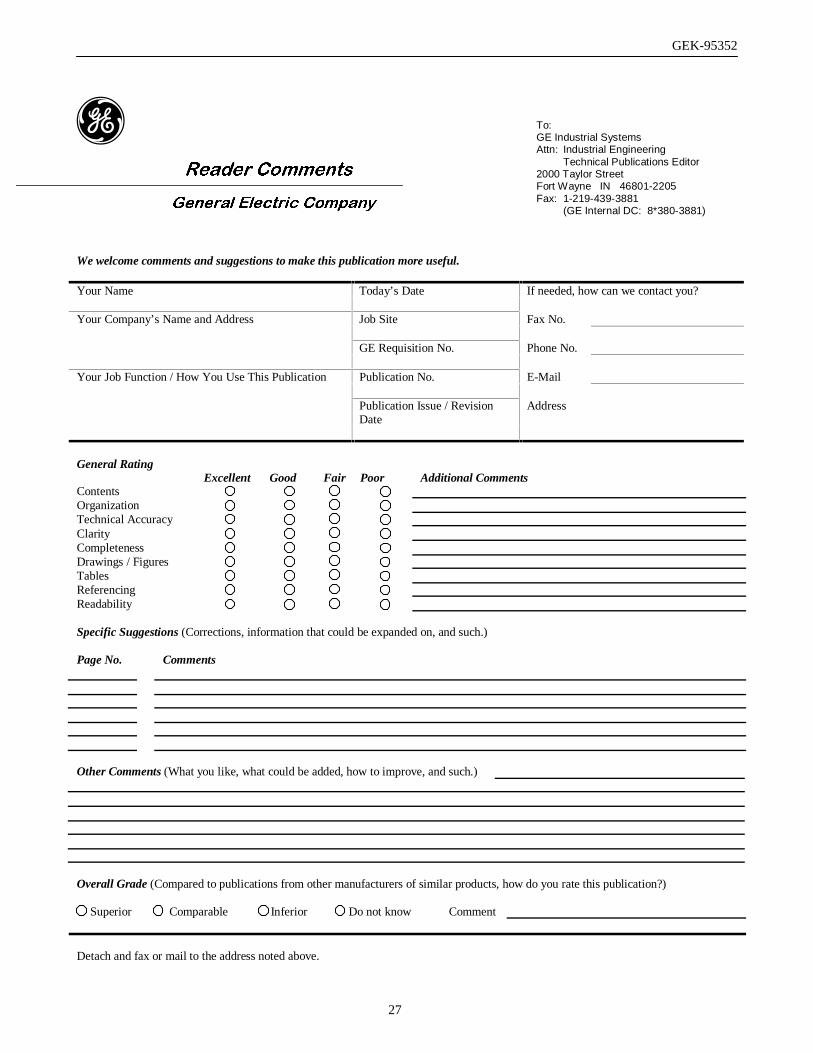
We welcome comments and suggestions to make this publication more useful.
Your Name Today’s Date If needed, how can we contact you?
Your Company’s Name and Address Job Site Fax No.
GE Requisition No. Phone No.
Your Job Function / How You Use This Publication Publication No. E-Mail
Publication Issue / RevisionDate
Address
General RatingExcellent Good Fair Poor Additional Comments
ContentsOrganizationTechnical AccuracyClarityCompletenessDrawings / FiguresTablesReferencingReadability
Specific Suggestions (Corrections, information that could be expanded on, and such.)
Page No. Comments
Other Comments (What you like, what could be added, how to improve, and such.)
Overall Grade (Compared to publications from other manufacturers of similar products, how do you rate this publication?)
Superior Comparable Inferior Do not know Comment
Detach and fax or mail to the address noted above.
To:GE Industrial SystemsAttn: Industrial Engineering
Technical Publications Editor2000 Taylor StreetFort Wayne IN 46801-2205Fax: 1-219-439-3881
(GE Internal DC: 8*380-3881)
GEK-95352
28
……………………………………………….…………………Fold here and close with staple or tape………………………………….………………….
Place
Stamp
Here
GE INDUSTRIAL SYSTEMSINDUSTRIAL ENGINEERING TECHNICALPUBLICATIONS EDITOR2000 TAYLOR STREETFORT WAYNE IN 46801-2205 USA
………………………………………………………………………………Fold Here first………………………………………………………………….

GEK-95352
29
Document Revision History
Rev # Date Author ISAAC # Description0 12/03/99 GJG N/A Conversion from PageMaker.