Instructions For Use - physiology.case.edu · Diagnostic Messages,1-4 Door,1-4 ... with the...
56
PN LL-IM-12AB October 2013 Instructions For Use Optima L Series Preparative Ultracentrifuges Beckman Coulter, Inc. 250 S. Kraemer Blvd. Brea, CA 92821 U.S.A.
Transcript of Instructions For Use - physiology.case.edu · Diagnostic Messages,1-4 Door,1-4 ... with the...

Instructions For Use
Optima L Series
Preparative Ultracentrifuges
October 2013
Beckman Coulter, Inc.
250 S. Kraemer Blvd.
Brea, CA 92821 U.S.A.
PN LL-IM-12AB

Optima L SeriesPreparative UltracentrifugesPN LL-IM-12AB (October 2013)
Copyright © 2013 Beckman Coulter, Inc.
All rights reserved
No part of this document may be reproduced or
transmitted in any form or by any means,
electronic, mechanical, photocopying, recording, or
otherwise, without prior written permission from
Beckman Coulter, Inc.
Beckman Coulter and the stylized logo are trademarks of
Beckman Coulter, Inc. and are registered in the USPTO.
All other trademarks, service marks, products, or services
are trademarks or registered trademarks of their
respective holders.
Find us on the World Wide Web at:
www.beckmancoulter.com
Made in U.S.A.
Printed in U.S.A.

Safety Notice
Read all product manuals and consult with Beckman Coulter-trained personnel before attempting to operate instrument. Do not attempt to perform any procedure before carefully reading all instructions. Always follow product labeling and manufacturer’s recommendations. If in doubt as to how to proceed in any situation, contact your Beckman Coulter Representative.
Alerts for Warning, Caution, and Note
WARNING
WARNING indicates a potentially hazardous situation which, if not avoided, could result in death or serious injury.
CAUTION
CAUTION indicates a potentially hazardous situation, which, if not avoided, may result in minor or moderate injury and/or mechanical damage. It may also be used to alert against unsafe practices.
NOTE NOTE is used to call attention to notable information that should be followed during installation, use, or servicing of this equipment.
Safety During Installation and/or Maintenance
This instrument is designed to be installed by a Beckman Coulter Field Service representative. Installation by anyone other than authorized Beckman Coulter personnel invalidates any warranty covering the instrument. Also, should the instrument need to be moved, a Beckman Coulter Field Service representative must reinstall and relevel the instrument in its new location.
Any servicing of this equipment that requires removal of any covers can expose parts which involve the risk of electric shock or personal injury. Make sure that the power switch is turned off and the instrument is disconnected from the main power source by removing the Mains (power) plug from the outlet receptacle, and refer such servicing to qualified personnel.
Do not replace any centrifuge components with parts not specified for use on this instrument.
PN LL-IM-12AB iii

Safety NoticeElectrical Safety
Electrical Safety
To reduce the risk of electrical shock, this instrument uses a three-wire electrical cord and plug to connect this equipment to earth-ground. Make sure that the matching wall outlet receptacle is properly wired and earth-grounded.
Do not place containers holding liquid on or near the chamber door. If they spill, liquid may get into the instrument and damage electrical or mechanical components.
Safety Against Risk of Fire
Fuses protect certain electrical circuits within this instrument against overcurrent conditions. For continued protection against the risk of fire, replace only with the same type and rating specified.
This instrument is not designed for use with materials capable of developing flammable or explosive vapors or hazardous chemical reactions. Do not centrifuge such materials (for example, chloroform or ethyl alcohol) in this instrument nor handle or store them near the centrifuge.
Mechanical Safety
For safe operation of the equipment, observe the following:
• Use only the Beckman Coulter rotors and accessories designed for use in this instrument.
• Do not exceed the maximum rated speed of the rotor in use.
• NEVER attempt to slow or stop a rotor by hand.
• Do not move the centrifuge while the drive motor is spinning.
• In the event of a power failure, do not attempt to retrieve the sample from the instrument for at least one hour. Then follow the instructions for recovery of the sample under CHAPTER 4, Troubleshooting and Maintenance.
Chemical and Biological Safety
Normal operation may involve the use of solutions and test samples that are pathogenic, toxic, or radioactive. Such materials should not be used in this instrument, however, unless all necessary safety precautions are taken.
• Handle body fluids with care because they can transmit disease. No known test offers complete assurance that they are free of micro-organisms. Some of the most virulent—Hepatitis (B and C) and HIV (I-V) viruses, atypical mycobacterium, and certain systemic fungi—further emphasize the need for aerosol protection. Handle other infectious samples according to good laboratory procedures and methods to prevent spread of disease. Because spills may generate aerosols, observe proper safety precautions for aerosol containment. Do not run toxic, pathogenic, or radioactive materials in a rotor without taking appropriate safety precautions.
PN LL-IM-12ABiv

Safety NoticeChemical and Biological Safety
Biosafe containment should be used when Risk Group II materials (as identified in the World Health Organization Laboratory Biosafety Manual) are handled; materials of a higher group require more than one level of protection.
• Dispose of all waste solutions according to appropriate environmental health and safety guidelines.
It is your responsibility to decontaminate the instrument and accessories before requesting service by Beckman Coulter Field Service.
PN LL-IM-12AB v

Safety NoticeChemical and Biological Safety
PN LL-IM-12ABvi

Contents
Safety Notice, iii
Alerts for Warning, Caution, and Note, iii
Safety During Installation and/or Maintenance, iii
Electrical Safety, iv
Safety Against Risk of Fire, iv
Mechanical Safety, iv
Chemical and Biological Safety, iv
Introduction, xiii
Instrument Certification, xiii
Scope of Manual, xiii
Conventions, xiv
Recycling Label, xiv
RoHS Notice, xv
Specifications, xvi
Preinstallation Requirements, xviii
CHAPTER 1: Description, 1-1
Introduction, 1-1
Power, 1-1Standby Mode, 1-1
Key Switch Positions, 1-1
Control Panel, 1-2Keys, 1-2Displays, 1-2Run Status Indicators, 1-3Diagnostic Messages, 1-4
Door, 1-4
Rotor Chamber, 1-4
vii

Contents
Vacuum System, 1-4
Temperature Sensing, 1-5
Temperature Control System, 1-5
Overspeed, 1-6
Rotor Energy System, 1-6
Drive, 1-6
Name Rating Plate, 1-6
CHAPTER 2: Run Preparation, 2-1
Introduction, 2-1
Power, 2-1
Key Switch Positions, 2-1
Standard Operation, 2-2Keypad, 2-2Parameter Keys, 2-3
Programmed Operation, 2-7
Activation Keys, 2-8
Delayed Start Program Function, 2-10Entering Program, 2-10Running Program 0 with a Second Program, 2-11Editing Settings During the Delayed Start Run, 2-11
CHAPTER 3: Run Procedure, 3-1
Introduction, 3-1
Standard Operation, 3-1
Repeating a Run, 3-2
Programmed Operation, 3-2
Delayed Start Program Function, 3-3
Zonal Operation, 3-4Acceleration, 3-5Deceleration, 3-5Unloading, 3-5
Points to Remember, 3-6
CHAPTER 4: Troubleshootingand Maintenance, 4-1
Introduction, 4-1
In Case of Power Failure During Run, 4-1
viii
Contents
Retrieving Your Sample, 4-1
Diagnostic Messages, 4-5
Cleaning, 4-7
Decontamination, 4-7
Sterilization and Disinfection, 4-7
Storage and Transportation, 4-8
Supply List, 4-8
Beckman Coulter, Inc.Optima L, LE, L-XP, and XL Preparative Ultracentrifuges Warranty
Related Documents
ix

Contents
x

xi
Illustrations
Illustrations
1.1 The Control Panel, 1-2
1.2 The Rotor Chamber, 1-5
2.1 Inserting the Key Into the Interlock Switch, 2-2
4.1 Removing the Control Head Cover, 4-2
4.2 Depressing the Latch to Loosen the Front Panel, 4-3
4.3 Interior View of Instrument (Door Removed), 4-4
4.4 Location of Diagnostic Messages on the Control Panel, 4-5

xii
Tables
Tables
1.1 Run Status indicators, 1-3
2.1 Vacuum LEDs, 2-9
4.1 Diagnostic Troubleshooting Chart, 4-6

Introduction
Instrument Certification
Beckman Coulter Optima L series ultracentrifuges are manufactured in a facility that maintains certifications to both ISO 9001:2008 and ISO 1348:2003. They have been designed and tested to be compliant (when used with Beckman Coulter rotors) with the laboratory equipment requirements of applicable regulatory agencies. Declarations of conformity and certificates of compliance are available at www.beckmancoulter.com.
Scope of Manual
This manual is designed to familiarize you with the Beckman Coulter Optima L-100K or L-90K Preparative Ultracentrifuge—its function, specifications, operation, and routine operator care and maintenance. Beckman Coulter recommends that you read this entire manual, especially the Safety Notice and all safety-related information, before operatingthe instrument or performing instrument maintenance.
• The following introductory pages contain the instrument specifications and preinstallation requirements.
• CHAPTER 1, Description provides a brief description of the instrument, the operating controls, and indicators.
• CHAPTER 2, Run Preparation explains how to use the control panel to enter run parameters for standard and programmed operation.
• CHAPTER 3, Run Procedure covers operating procedures for both kinds of runs.
• CHAPTER 4, Troubleshooting and Maintenance lists possible malfunctions, together with probable causes and corrective actions, and maintenance procedures.
NOTE If the ultracentrifuge is used in a manner other than specified in this manual, the safety and performance of this instrument could be impaired. Further, the use of any equipment other than that intended for use by Beckman Coulter has not been evaluated for safety. Use of any equipment not specifically recommended in this manual is the sole responsibility of the user.
PN LL-IM-12AB xiii

IntroductionConventions
Conventions
Certain symbols are used throughout this manual to call attention to safety-related and other important information. The symbols used are reproduced on the inside back cover of this manual.
Typographic Conventions
Certain typographic conventions are used throughout this manual to distinguish names of user interface components, such as keys and displays.
• Key names (for example, START or ENTER/RECALL) and display names (for example, TEMP°C or SPEED-RPM) appear in bold type.
Recycling Label
This symbol is required in accordance with the Waste Electrical and Electronic Equipment (WEEE) Directive of the European Union. The presence of this marking on the product indicates.
1. the device was put on the European market after August 13, 2005 and
2. the device is not to be disposed via the municipal waste collection system of any member state of the European Union.
It is very important that customers understand and follow all laws regarding the proper decontamination and safe disposal of electrical equipment. For Beckman Coulter products bearing this label please contact your dealer or local Beckman Coulter office for details on the take back program that will facilitate the proper collection, treatment, recovery, recycling and safe disposal of the device.
A28219-AA
PN LL-IM-12ABxiv
IntroductionRoHS Notice
RoHS Notice
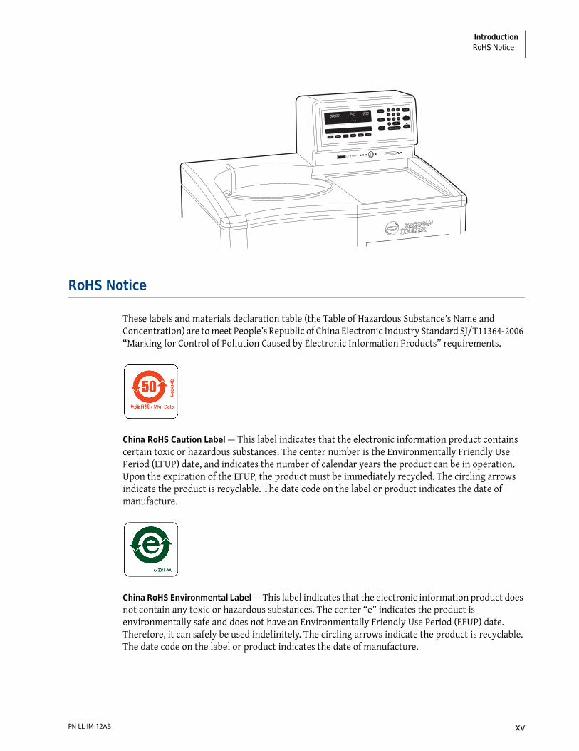
These labels and materials declaration table (the Table of Hazardous Substance’s Name and Concentration) are to meet People’s Republic of China Electronic Industry Standard SJ/T11364-2006 “Marking for Control of Pollution Caused by Electronic Information Products” requirements.
China RoHS Caution Label — This label indicates that the electronic information product contains certain toxic or hazardous substances. The center number is the Environmentally Friendly Use Period (EFUP) date, and indicates the number of calendar years the product can be in operation. Upon the expiration of the EFUP, the product must be immediately recycled. The circling arrows indicate the product is recyclable. The date code on the label or product indicates the date of manufacture.
China RoHS Environmental Label — This label indicates that the electronic information product does not contain any toxic or hazardous substances. The center “e” indicates the product is environmentally safe and does not have an Environmentally Friendly Use Period (EFUP) date. Therefore, it can safely be used indefinitely. The circling arrows indicate the product is recyclable. The date code on the label or product indicates the date of manufacture.
STOP
VACUUM—µ
SPEED—RPMTIME—HR:MIN TEMP—°C
POWER OFF
X 10,000
SAVEPROGHOLDw2tDECELACCEL
VACUUM
START
STOP
TIME
TEMP
CE0
1 2 3
4 5 6
7 8 9SPEED
ENTER/RECALL
PN LL-IM-12AB xv

IntroductionSpecifications
Specifications
Control Panel
Only values with tolerances or limits are guaranteed data. Values without tolerances are informative data, without guarantee.
Specifications Description
Speed • Set speed:
— 1000 rpm to maximum speeda in increments of 100 rpm
• Speed control:— Actual rotor speed will be ±20 rpm of the set speed (above 1000 rpm)
• Speed display:— Indicates rotor speed in increments of 10 rpm at speeds below 1000 rpm, and
increments of 100 rpm at speed above 1000 rpm
Time • Set time:— Up to 99 hours and 59 minutes; HOLD for runs of unspecified length
• Time display:— Indicates time remaining in timed runs, time elapsed in HOLD runs, and
estimated time remaining in ω 2t runs
Temperature • Set temperature:— 0 to 40°C in increments of 1°C
• Temperature control:— ±0.5°C of set temperature
• Temperature display:— Indicates rotor temperature in increments of 0.1°C
• Temperature stability— Within 0.3°C of set after equilibration
• Ambient temperature range:— 15 to 40°C
ω 2t Integrator • Set ω 2t
— Up to 9.99 × 10¹⁴ radians squared per second
• ω 2t display— Shows accumulated centrifugal force to three significant digits (in
exponential notation)
Acceleration Selection from two profiles: maximum acceleration from 0 rpm to set speed, or slow acceleration from 0 to 500 rpm, followed by maximum acceleration to set speed
Deceleration Selection from three profiles: full dynamic braking to 0 rpm, slow (full brake to 500 rpm followed by reduced braking to a gentle stop), or no brake
PN LL-IM-12ABxvi

IntroductionSpecifications
Operational Features
NOTE The Optima L series ultracentrifuges have been designed and tested to operate safely indoors at altitudes up to 2000 m (6562 ft).
Physical Data
Operation Standard, programmed, or delayed start; instrument memory can store up to nine programs
Key Switch Used to select normal or zonal operation
a. Maximum speed will be 100,000 rpm or 90,000 rpm for the current models. Models purchased earlier may include maximum speeds of 80,000, 70,000, or 60,000 rpm.
Specifications Description
Specifications Description
Revolution Counter
Displays accumulated total number of rotor revolutions in tens of thousands
Barrier Ring 41-mm (1.63-in.) heat-treated steel alloy armor ring surrounded by a 12-mm (0.50-in.) steel vacuum chamber to provide full protection for the operator
Door 17.5-mm (0.69-in.) high-strength structural steel
Vacuum Diffusion pump in series with a mechanical pump typically reduces chamber pressure to below 5 microns (0.7 Pa)
Instrument Classification
S (uses all Beckman Coulter preparative rotors except Types 35 and 42.1 rotors with serial numbers 1299 or lower)
Diagnostic Messages
See CHAPTER 4, Troubleshooting and Maintenance
Specifications Description
Weight 465 kg (1025 lb)
Height (overall) 120.7 cm (47.5 in.)
Width 94.0 cm (37 in.)
Depth 67.3 cm (26.5 in.)
Ventilation clearances 5.1 cm (2 in.) sides; 15.2 cm (6 in.) rear
Finishes • Keypad— coated polycarbonate
• Top surface— urethane paint
• Other surfaces— acrylic baking enamel
Maximum heat dissipation into the room 1.0 kW (3400 Btu/hr)
PN LL-IM-12AB xvii

IntroductionPreinstallation Requirements
Preinstallation Requirements
CAUTION
Do not attempt to install or turn on the power to the instrument. Its purchase price includes installation by Beckman Coulter personnel. Installation by anyone other than authorized Beckman Coulter personnel invalidates the warranty.
Preinstallation requirements have been sent prior to shipment of the instrument. (Copies may also be attached to the outside of the shipping container and are available at www.beckmancoulter.com.) The following information is provided in case the ultracentrifuge must be relocated. Contact your Beckman Coulter Field Service representative to adjust and level the instrument if it must be moved.
Electrical Data
To reduce the risk of electrical shock, this equipment uses a three-wire electrical cord (1.8 m; 6 ft) and plug to connect the equipment to earthground. In regions where the instrument is supplied with an unterminated cord, a plug that meets local electrical and safety requirements must be supplied. (Contact your local Beckman Coulter office for specific information regarding these
Humidity restrictions <95% (non-condensing)
Noise level measured 0.91 m (3 ft) in front of the instrument
<57 dBa
Installation (overvoltage) category II
Pollution degree 2a
a. Normally only nonconductive pollution occurs; occasionally, however, a temporary conductivity caused by condensation must be expected
Specifications Description
Instrument rating: 220 to 240 VAC, 50 Hz, 20 A 200 to 240 VAC, 50/60 Hz, 20 A
Power line range: 180 to 264 VAC, 60 or 50 Hz (single-phase), 30 A
Electrical supply: Class I
PN LL-IM-12ABxviii

IntroductionPreinstallation Requirements
requirements.) See the Table below for the required wire connections. Make sure that the matching wall outlet receptacle is properly wired and earth-grounded.
To ensure safety, the instrument should be wired to a remote emergency switch (preferably outside the room where the centrifuge is housed, or adjacent to the exit from that room). In case of a malfunction, the centrifuge can be disconnected from the main power source by removing the Mains (power) plug from the outlet receptacle.
Optima L series ultracentrifuges have been designed and tested to operate safely indoors at altitudes up to 2000 m (6562 ft).
Space
Locate the Optima L in a clean, safe, uncluttered environment. Be sure to provide a 5.1-cm (2-in.) clearance on each side, as the feet extend about 5.1 cm (2 in.) beyond the instrument (see the Figure below). (The pads under each foot have been designed to prevent possible rotation of the instrument in the event of a rotor mishap.) A 15.2-cm (6-in.) clearance is required at the rear of the instrument for servicing the control panel and to ensure sufficient air ventilation during operation. The ultracentrifuge must have adequate air ventilation to ensure compliance to local requirements for vapors produced during operation.
1. 30-ampere Circuit Protector2. Measured Line Voltage3. North American Plug
4. Wall Outlet Hubbell 9330, Bryant 96-30 FR, or Equivalent (NEMA 6-30R)
5. Earth Ground
Required Wired Connection
Wire Insulation Color Terminal
Symbol
Harmonized North American
Green/Yellow Earth ground
Light Blue Neutral N L
Brown Live or Line L L
1
1
5
2
34
PN LL-IM-12AB xix

IntroductionPreinstallation Requirements
The Mains (power) plug is the disconnect device and must remain easily accessible. Position the ultracentrifuge so that it is easy to remove the Mains (power) plug from the outlet receptacle.
The instrument will operate within specifications in a laboratory with ambient temperatures ranging from 15 to 40°C.
WARNING
Do not place the instrument near areas containing flammable reagents or combustible fluids.
Bio-Safety Level 3 Installation
For laboratories with epoxy aggregate floors, such as BSL-3 labs, a non-invasive installation kit (PN 393862) is available. The kit, which consists of a high-strength adhesive tape, is CSA certified for use on epoxy aggregate floors only.
cmin.
94.037
5.12
5.12
67.326.5
15.26
PN LL-IM-12ABxx

CHAPTER 1
Description
Introduction
The Optima L-100K or L-90K Preparative Ultracentrifuge, classified S, is used to generate centrifugal forces for the separation of particles. The instrument can be used with all available Beckman Coulter rotors for standard and zonal operation.
This section describes the control panel and the instrument’s major components.
Power
A circuit breaker, labeled on (I) and off (O), is located on the right side of the instrument and controls electrical power to the instrument. Power may be left on at all times (see Standby Mode below) except in the case of an emergency or when maintenance is required.
A red POWER OFF button is provided on the front of the instrument for emergency use. Pressing the POWER OFF button trips the circuit breaker to the down position. To return power to the instrument, the circuit breaker must be switched back up.
Standby Mode
When the instrument is at rest, it automatically goes into standby mode, using only minimal power. To restore the instrument to operating mode, press any key and it becomes fully operational.
Key Switch Positions
A key interlock switch is used to select normal or zonal operation. The normal position is used for routine closed-door centrifugation and the zonal position for runs in which a zonal rotor is loaded and unloaded while spinning.
PN LL-IM-12AB 1-1

DescriptionControl Panel
Control Panel
Figure 1.1 shows the front control panel. Refer to this illustration to locate the keys and displays described below.
Figure 1.1 The Control Panel
Keys
Parameter keys are used to enter the run conditions. They include SPEED, TIME, and TEMP to the left of the keypad and ACCEL, DECEL, w2t, HOLD, PROG, and SAVE along the bottom of the display area.
Activation keys are designated to control specific ultracentrifuge functions. These are VACUUM, START and STOP, located to the right of the keypad. (All keys are discussed in more detail in the next section.)
The keypad is used for entering numerical values. In addition to keys 0 through 9, the keypad includes a CE (Clear Entry) key and ENTER/RCALL key.
Displays
Digital displays indicate rotor speed, run time, rotor temperature, the ω2t value (when in that mode), and the selected program number (if used). The displays serve a dual purpose.
1. Parameter Keys2. Keypad3. Activation Keys
4. Location of Diagnostic Messages5. Parameter Keys
VACUUM–µ
SPEED–RPM TIME–HR:MIN
POWER OFF X 10,000
SAVE PROG HOLD w2t DECEL ACCEL
VACUUM
START
STOP
TIME
TEMP
CE 0
1 2 3
4 5 6
7 8 9 SPEED
ENTER/RECALL
1 2 3
4
5
PN LL-IM-12AB1-2

DescriptionControl Panel 1
Actual (Current) Values
When the power is on, the displays show the actual operating conditions at all times except when the instrument is in the editing mode or when ENTER/RCALL has been pressed (see below).
Set Values
Set values are the run conditions entered by the user. When you press a parameter key, the associated display blinks to indicate that a value can be entered or modified. This is referred to as the editing mode.
The display continues to blink until you press another parameter key or ENTER/RCALL. If you press another parameter key, the associated display begins to blink and the set values continue to be displayed. If you press ENTER/RCALL, the instrument displays the set values for 5 seconds, then exits the editing mode and returns to showing actual conditions. Set values remain in memory until new values are entered.
Whenever you press ENTER/RCALL the instrument displays the set values for 5 seconds, then returns to showing actual conditions.
Run Status Indicators
Run indicators are provided in the form of green and red LEDs to indicate the status of the instrument. Figure 1.1 shows the location of the LEDs on the control panel and Table 1.1 describes the meaning of each. (Unless otherwise noted, the LEDs appear above their respective keys.)
Table 1.1 Run Status indicators
Key Pressed Description of Run Status Indicators
START A green LED on the START key lights when the key is pressed. It blinks until the rotor reaches set speed and then shines continuously until the run ends or STOP is pressed.
STOP A green LED on the STOP key lights when either the key is pressed or the rotor begins to decelerate. It blinks until the rotor comes to a stop.
ACCEL MAX or SLOW indicates which acceleration profile has been selected.
DECEL MAX, SLOW, or NO BRAKE indicates which deceleration profile has been selected.
ω2t ω
2t indicates that the ultracentrifuge is in the ω 2t mode.
HOLD HOLD indicates that the ultracentrifuge is in the HOLD mode.
PROG A number (1 through 9) above the PROG (program) key indicates the number of the program that has been selected for the run.
PN LL-IM-12AB 1-3

DescriptionDoor
Diagnostic Messages
Diagnostic messages appear as red LEDs under the SPEED display (see Figure 1.1) to alert you to conditions that may need your attention. The indicators are not normally visible; however, if an abnormal condition occurs, the appropriate message(s) will appear.
The meanings of the diagnostic messages, as well as appropriate actions to take, are discussed in CHAPTER 4, Troubleshooting and Maintenance.
Door
The chamber door is made of high-strength structural steel. A solenoid interlock prevents it from being opened during operation. The door can be opened only by using the door handle and only if the power is on and the vacuum is off, with the chamber at atmospheric pressure. Refer to CHAPTER 4, Troubleshooting and Maintenance, for instructions on accessing the chamber to retrieve a sample in case of a power outage.
Rotor Chamber
The rotor chamber is made of aluminum, coated with a chemical-resistant epoxy finish. The rotor drive spindle, radiometer, photoelectric devices, and safety plate are visible in the bottom of the chamber (Figure 1.2).
Vacuum System
The vacuum system is automatically activated when ENTER/RECALL and START are pressed, or it may be turned on directly by pressing the VACUUM key. Three vacuum LEDs, labeled 750, 200, and <20, are located in the middle of the upper display to indicate the level of chamber pressure in microns.
SAVE SAVE blinks to indicate that you may save the program values just entered. Press SAVE and the values will be saved in memory under the assigned program number.
VACUUM 750, 200, and <20 (microns) — located in the upper display — indicate the approximate chamber pressure as the chamber is being evacuated. Only one LED will be on continuously at any given time. Once below 20 microns the <20 LED shines continuously until the VACUUM key is pressed to vent the chamber. (The instrument will typically draw vacuum to 5 microns or less.)
Table 1.1 Run Status indicators (Continued)
Key Pressed Description of Run Status Indicators
PN LL-IM-12AB1-4

DescriptionTemperature Sensing 1
Figure 1.2 The Rotor Chamber
At the end of a run, the chamber vacuum must be vented (by pressing VACUUM) before the door can be opened. After the door is opened, the chamber is brought to approximate room temperature to prevent condensation from collecting in the chamber. (To help keep the chamber dry and clean, the door should be kept closed whenever possible.)
A purge system removes significant amounts of moisture from the vacuum pump and chamber. If it takes a long time to pull a vacuum, however, it is likely caused by excess moisture in the system. Refer to CHAPTER 4, Troubleshooting and Maintenance, for information on correcting this condition.
Temperature Sensing
Rotor temperature is detected by a radiometer mounted in the bottom of the rotor chamber (see Figure 1.2) when the chamber pressure is below 100 microns. When above 100 microns (or if the radiometer fails), chamber temperature is measured by a thermistor mounted in the chamber.
Temperature Control System
The instrument uses a solid-state thermoelectric refrigeration and heating system, which eliminates the need for a complex, conventional refrigeration system and heater. Neither Freon nor water is needed; the only coolant required is forced air from the cooling fans.
After the power is turned on, the temperature control system is activated when the door is closed and the vacuum system is turned on. The rotor temperature is controlled to ±0.5°C of the set value.
1. Drive Spindle2. Safety Plate
3. Photoelectric Devices4. Radiometer
1
2
3
4
PN LL-IM-12AB 1-5

DescriptionOverspeed
If the temperature system malfunctions, the TEMP diagnostic message will appear and the rotor will decelerate to a stop.
Overspeed
The overspeed system is a safety feature designed to ensure that the rotor does not exceed its maximum allowable speed. This system includes photoelectric sensors in the rotor chamber next to the drive spindle (see Figure 1.2) and an overspeed disk on the bottom of the rotor. Individual rotor manuals provide information on the correct overspeed disks to be used with each rotor.
The overspeed disk has alternating light and dark sectors. As the rotor spins, the passage of reflecting and nonreflecting sectors over the photoelectric device generates a series of pulses that are detected by electronic circuitry. If the pulse rate, which is dependent on the number of sectors on the disk and the speed of the rotor, exceeds a set limit, the SPEED diagnostic message will light and the rotor will automatically coast to a stop.
When the rotor reaches 1000 rpm, the set speed is checked against the overspeed disk. If the overspeed disk indicates a maximum allowable speed that is lower than the set speed, the set speed is automatically lowered to the maximum speed permitted by the disk and a SPEED diagnostic message is displayed to alert you to the change. (In the ω2t mode, the time setting is recalculated to give an equivalent ω2t value.)
Rotor Energy System
As the rotor accelerates between 15,000 and 21,000 rpm, rotor inertia is measured and the rotor energy is calculated for the speed set by the user. If the calculated rotor energy is determined to be excessive, a SPEED diagnostic message will appear and the instrument will immediately shut down.
Drive
The Optima L series ultracentrifuges use a frequency-controlled, air-cooled direct-drive induction motor that requires no gears or brushes. In addition, the drive does not require an oil vacuum seal, external oil reservoir, or continuously operating damper. Externally cooled by forced air and internally cooled by oil, the drive delivers ultrasmooth, quiet performance, with high tolerance of rotor imbalance.
Name Rating Plate
A name rating plate is affixed to the rear of the instrument. Always mention the serial number (located on the chamber door) and model number when contacting Beckman Coulter regarding your Optima L series instrument.
PN LL-IM-12AB1-6

CHAPTER 2
Run Preparation
Introduction
This section explains how to use the control panel to enter run information. Refer to Figure 1.1 for the location of keys and indicators.
Power
If the power to the instrument is off, flip the circuit breaker at the right side of the instrument on. Do not turn the instrument power off except when maintenance is necessary or in the case of an emergency. The instrument automatically goes into a standby mode when not in operation; pressing any key makes the instrument fully operational once again.
Key Switch Positions
1 Insert the key into the interlock on the control head to select normal or zonal operation.
• The arrow on the key should point in the direction of the icon representing the selected operation.
• These icons (Figure 2.1) are displayed next to the interlock on the instrument.
2 Turn the key to the right to select the normal position for standard and programmed closed-door centrifugation.
The key should be removed while the instrument is in this mode.
PN LL-IM-12AB 2-1
Run PreparationStandard Operation
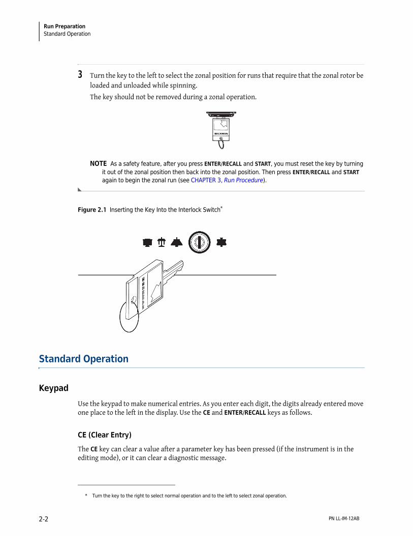
3 Turn the key to the left to select the zonal position for runs that require that the zonal rotor be loaded and unloaded while spinning.
The key should not be removed during a zonal operation.
NOTE As a safety feature, after you press ENTER/RECALL and START, you must reset the key by turning it out of the zonal position then back into the zonal position. Then press ENTER/RECALL and START again to begin the zonal run (see CHAPTER 3, Run Procedure).
Figure 2.1 Inserting the Key Into the Interlock Switch*
Standard Operation
Keypad
Use the keypad to make numerical entries. As you enter each digit, the digits already entered move one place to the left in the display. Use the CE and ENTER/RECALL keys as follows.
CE (Clear Entry)
The CE key can clear a value after a parameter key has been pressed (if the instrument is in the editing mode), or it can clear a diagnostic message.
* Turn the key to the right to select normal operation and to the left to select zonal operation.
PN LL-IM-12AB2-2

Run PreparationStandard Operation 2
1 Press CE once to clear a numerical entry.
2 Press CE twice to exit from the editing mode.
The display will stop blinking and the actual values will reappear.
3 Press CE once to clear a diagnostic message (see CHAPTER 4, Troubleshooting and Maintenance for more information.)
Enter/Recall
Use the ENTER/RECALL key to enter or display values as follows.
1 Press ENTER/RECALL to enter a set value into memory.
2 Press ENTER/RECALL at any time to display the settings for 5 seconds.
After 5 seconds, the displays show the actual conditions again.
3 Press ENTER/RECALL and then START within 5 seconds to start a run.
4 Press ENTER/RECALL and then STOP within 5 seconds to display the STOP values—that is, the values that existed when the rotor began decelerating.
Parameter Keys
Follow the instructions below for using the parameter keys and keypad to enter run settings.
SPEED
The run speed can be set between 1000 rpm and 100,000 rpm (L-100K) or 90,000 rpm (L-90K) in increments of 100 rpm. When entering the set speed, the last two digits in the SPEED-RPM display remain fixed as zeros and cannot be changed. Speeds between 0 and 1000 rpm are shown in increments of 10 (for example, 980 rpm). Speeds above 1000 rpm are shown in increments of 100 (for example, 45,600 rpm).
To enter or modify the set speed:
1 Press SPEED.
The value in the SPEED display blinks.
PN LL-IM-12AB 2-3

Run PreparationStandard Operation
2 Use the keypad to enter or modify the speed.
If you try to enter an invalid number the instrument will beep twice.
Press CE to clear the value, then enter a valid speed.
3 Press another parameter key or ENTER/RECALL to save the set speed.
After ENTER/RECALL and START have been pressed, the set speed is checked against the overspeed disk at 1000 rpm. If the speed setting is greater than that allowed by the overspeed disk, the run will continue, but the rotor speed will be adjusted to the maximum speed permitted by the disk. The TIME setting is also changed to provide an equivalent ω2t value, if in the ω2t mode. A SPEED diagnostic message will appear, indicating that these changes have been made. Press CE to clear the message.
• You may change the set speed at any time by repeating the steps listed above. The rotor will accelerate or decelerate to the new speed.
• The rotor will not accelerate beyond 3000 rpm until the chamber pressure drops below 750 microns. At that point, the rotor accelerates to set speed.
• If any speed-related malfunction occurs, a SPEED diagnostic message will appear. Consult Table 4.1, Diagnostic Troubleshooting Chart in CHAPTER 4 for details.
• A special delayed start program function automatically sets the speed at 0 rpm. This function is described at the end of this section.
TIME
How the run is terminated depends upon the time mode selected (TIME, ω2t, or HOLD). The information that appears in the TIME-HR: MIN display also depends upon the mode selected. (The TIME mode is discussed here; a description of HOLD and ω2t modes follow.)
The run time can be set up to 99 hours and 59 minutes. During the run, the display indicates the time remaining in hours and minutes.
To enter or modify the set time:
1 Press TIME.
The value in the TIME display blinks.
2 Use the keypad to enter the run time in hours and minutes.
3 Press another parameter key or ENTER/RECALL to save the run time.
If you entered a number that is between 60 and 99 minutes, the instrument automatically recalculates the time in hours and minutes.
PN LL-IM-12AB2-4

Run PreparationStandard Operation 2
When ENTER/RECALL and START have been pressed, the instrument checks to make sure that a value has been entered in the TIME display, that a value for ω2t, has been entered in the speed display, or that the HOLD mode has been selected. In the TIME mode, the TIME display begins counting down as the rotor begins to spin. When the TIME display reaches zero, the run ends and the rotor automatically decelerates to a stop.
w2t (Accumulated Centrifugal Effect
The ω2t, display indicates the accumulated centrifugal effect in radians squared per second, to three significant figures, using exponential notation. The ω2t, can be set for up to 9.99 × 10¹⁴. Deceleration begins when the set ω2t, value is reached. The ω2t, value is shown in the SPEED display when the instrument is in the ω2t, mode and the w2t key is pressed.
To enter or modify the set �2t, value:
1 Press w2t.
The value in the SPEED display blinks.
2 Use the keypad to enter an ω2t, value.
• An “E” remains stationary in the hundreds place, to indicate that the last two places represent the exponent.
• If you enter an invalid number, such as 0E22, the instrument will beep twice.
• Press CE to clear the value, then enter a valid number.
3 Press another parameter key or ENTER/RECALL to save the ω2t value. The ω2t indicator will light
In the ω2t mode, a calculation of the time remaining (until the set ω2t value is reached) is shown in the TIME display. (If the calculation exceeds 99 hours and 59 minutes, four dashes will appear in the TIME display.)
After the run, pressing ENTER/RECALL, STOP, and w2t in succession will show the accumulated ω2t value (in the SPEED display) when the rotor began to decelerate. After 5 seconds, the display returns to showing actual conditions.
The ω2t indicator will remain on until a different run mode is selected as a reminder that the instrument is still in the ω2t mode. The accumulated ω2t from the previous run will automatically return to zero when ENTER/RECALL and START are pressed to begin a new run.
Example: To enter 3.24 × 10¹² as the ω2t value:
• Press w2t. • Press 3, 2, 4, 1, 2 in that order. (The display will show “3.24E12.”) • Press another parameter key or ENTER/RECALL.
PN LL-IM-12AB 2-5

Run PreparationStandard Operation
HOLD
The HOLD mode is used for runs of unspecified lengths or runs that will last longer than 99 hours and 59 minutes. When ENTER/RECALL is pressed while the instrument is in this mode, the word HOLD appears in the TIME display for 5 seconds. The display will then return to showing the time elapsed since the beginning of the run.
To select the HOLD mode:
1 Press HOLD. The HOLD indicator lights to indicate that the instrument is in this mode. The word HOLD appears in the TIME display.
2 Press the next parameter key or ENTER/RECALL.
• After ENTER/RECALL and START have been pressed, the run will continue indefinitely until you press STOP.
• If the run exceeds 99 hours and 59 minutes, dashes will appear in the TIME display.
TEMP (Temperature)
The temperature can be set between 0 and 40°C in increments of 1°C. If no other value has been entered, the instrument automatically selects 25°C as the default operating temperature.
To enter or modify the set temperature:
1 Press TEMP.
The TEMP display blinks.
2 Use the keypad to enter the required temperature.
• If you enter an invalid value, such as 60°C, the instrument will beep twice.
• Press CE to clear the value, then enter a valid temperature.
3 Press another parameter key or ENTER/RECALL to save the set temperature.
The set temperature can be changed at any time by repeating the steps above. The rotor temperature will be adjusted accordingly.
Actual rotor temperature, after equilibration, is controlled to ±0.5°C of the set value. If the temperature system malfunctions, the TEMP diagnostic message will light, and the rotor will decelerate to a stop.
PN LL-IM-12AB2-6

Run PreparationProgrammed Operation 2
Accel (Acceleration)
The instrument has two acceleration profiles: maximum (MAX) and SLOW.
1 Press the ACCEL key repeatedly to toggle between the settings.
The run status indicator for the selected setting will light.
Decel (Deceleration)
The instrument has three deceleration profiles: MAX, SLOW, and NO BRAKE.
1 Press the DECEL key repeatedly to toggle between the settings.
The run status indicator for the selected setting will light.
Programmed Operation
PROG (Program) and SAVE
Up to nine sets of user-specified run conditions, called programs, may be stored. Each program is stored by number and can be recalled by using the keypad. Programs are retained in memory even when the power is turned off.
You can select an existing program by pressing the program number (1 to 9) on the keypad, or by pressing the PROG key repeatedly until the required set of parameters appears.
To create or modify a program:
1 Press PROG.
• If no program has been previously selected, a dash will appear above the PROG key.
• Actual values remain in the other displays.
2 Use the keypad to select a program number, which replaces the dash in the display.
a. Or, continue pressing PROG until the required program number appears.
The program number blinks to indicate that you are editing the program.
3 Use the parameter keys and keypad to enter the run settings.
a. After all parameters have been entered, press ENTER/RECALL.
The SAVE indicator will begin to blink to indicate that you may save the program.
PN LL-IM-12AB 2-7

Run PreparationActivation Keys
4 Press SAVE and the program will be stored in memory under the selected number.
Actual values will reappear in the displays.
To select a program for use:
1 Press PROG.
2 Press the required program number.
3 Press ENTER/RECALL and START.
To modify a parameter during the run without changing the program, change the setting as described above and then press ENTER/RECALL. Do NOT press SAVE. The instrument will run using the modified settings. The lighted number above the PROG key will go out to indicate that the instrument is no longer running from program memory.
Activation Keys
Use the activation keys to control the following ultracentrifuge functions.
VACUUM
1 The vacuum system is activated automatically when you press ENTER/RECALL and START to begin a run.
2 To evacuate the chamber at another time, make sure the chamber door is closed, then press VACUUM.
The chamber door can be opened only when the vacuum has been completely vented and the rotor is at rest.
When the run begins, the rotor will not accelerate past 3000 rpm until the chamber pressure drops below 750 microns. At that time, the rotor accelerates to set speed.
As the vacuum system begins to evacuate the chamber, a series of three LEDs (labeled 750, 200, and <20 microns) blink, remain lighted, or go off to allow you to monitor the change in pressure (see Table 2.1). When the pressure drops below 20 microns, the < 20 LED will remain lit until VACUUM is pressed to vent the chamber at the end of the run.
PN LL-IM-12AB2-8

Run PreparationActivation Keys 2
START
1 Press ENTER/RECALL and START to begin a run.
If you press only START, the instrument will not be activated.
a. If this occurs, press ENTER/RECALL and START again to begin the run.
• After you have pressed ENTER/RECALL and START, the instrument checks to see if there is an entry in the TIME display, or if ω2t or HOLD has been selected.
• If there is no entry, the instrument will beep twice and the TIME display will begin blinking.
2 Enter a value and press ENTER/RECALL to set the value into memory.
(The instrument automatically uses 25°C as the default temperature if another temperature value has not been entered.)
a. Then press ENTER/RECALL and START again to begin the run.
• As the rotor begins to accelerate, the green LED on the START key blinks.
• When the rotor reaches set speed, the LED stops blinking and remains on until the run has ended or STOP is pressed.
Use the STOP key to do the following:
STOP
1 Press STOP at any time to terminate the run.
A green LED on the key will blink to indicate that the rotor is decelerating; a tone will sound when the rotor comes to a stop and the green LED will turn off.
2 Press ENTER/RECALL and STOP within 5 seconds to display the run conditions that existed when the rotor began decelerating.
These are called the STOP values.
Table 2.1 Vacuum LEDs
Pressure 750 LED 200 LED <20 LED
750 or above
220 to 750
20 to 200
<20
blinking
lit
off
off
off
blinking
lit
off
off
off
blinking
lit
PN LL-IM-12AB 2-9

Run PreparationDelayed Start Program Function
3 Press ENTER/RECALL, STOP, and w2t in succession to display the accumulated ω2t at the time the rotor began decelerating.
The ω2t value is displayed in the SPEED display.
Delayed Start Program Function
The delayed start program function allows you the convenience of delaying the start of a run so that it begins and ends at the time you require—without you having to be there to start the run. For example, if you require a four-hour run to end at 8:00 a.m., you can program the instrument to hold the rotor at a specified temperature and time at zero speed and then automatically begin the run at 4:00 a.m.
To use the delayed start program function, a special program (called program 0) is created, followed by a second program that contains the run conditions. Follow the instructions below.
Entering Program
The first program —program 0— is used to delay the start of the run until the required time. Enter the settings as follows.
1 Press PROG then 0 on the keypad to access program 0.
• A blinking zero will appear above the PROG key.
• The display area will show the existing settings for program 0.
2 Use the parameter keys and keypad to enter time and temperature settings as required.
• You cannot change the speed setting, which is set at zero.
• If you try to change it, the instrument will signal an error.
3 Press ENTER/RECALL.
The SAVE message will blink to indicate that you can save the program settings.
4 Press SAVE to save program 0.
PN LL-IM-12AB2-10

Run PreparationDelayed Start Program Function 2
Running Program 0 with a Second Program
To run program 0 followed by another program, do the following.
1 Press PROG then 0 on the keypad to access program 0.
• A blinking zero will appear above the PROG key.
• The display area will show the existing settings for program 0.
2 Use the keypad to select a second program from the stored programs.
The program settings selected will appear in the display and the program number will appear in the PROG display.
a. Press ENTER/RECALL.
3 To begin the delayed start program function, press ENTER/RECALL and START.
• The word “delay” will appear in the SPEED display and the second program number you selected will appear in the PROG display.
• When the time in program 0 reaches zero, the second program will begin automatically.
Editing Settings During the Delayed Start Run
NOTE If you change a run setting during program 0, the second program is automatically canceled because the instrument is no longer in the program mode. The instrument will stop at the end of program 0.
1 To edit a setting during the run (without permanently changing the program), use the parameter keys and keypad as described above.
a. Then press ENTER/RECALL.
b. Do NOT press SAVE.
• The instrument will run using the modified settings.
• The lighted number above the PROG key will go out to indicate that the instrument is no longer running from program memory.
Example: To run programs 0 and 3:
— Press PROG, 0, 3, and ENTER/RECALL.— Press ENTER/RECALL and START.
PN LL-IM-12AB 2-11

Run PreparationDelayed Start Program Function
PN LL-IM-12AB2-12

CHAPTER 3
Run Procedure
Introduction
This section summarizes standard, programmed, and zonal operation as well as the delayed start function. Use any of the acceptable Beckman Coulter rotors, consulting the applicable rotor manual and the Rotors and Tubes Manual (LR-IM) for instructions on preparing the rotor and accessories for centrifugation. For fast temperature equilibration, refrigerate or warm the rotor to the required temperature before the run.
WARNING
Do not use the ultracentrifuge in the vicinity of flammable liquids or vapors, and do not run such materials in the instrument. Do not lean on the instrument or place items on it while it is operating.
WARNING
Normal operation may involve the use of solutions and test samples that are pathogenic, toxic, or radioactive. Operator error or tube failure may generate aerosols. Do not run toxic, pathogenic, or other hazardous materials in this instrument unless you take all appropriate safety precautions. Ask your laboratory safety officer to advise you about the level of containment required for your application and the proper decontamination or sterilization procedures to follow if fluids escape from containers. Make sure that such procedures will not damage the instrument (see CHAPTER 4, Troubleshooting and Maintenance for more detailed information and refer to Appendix A in Rotors and Tubes).
The power must be turned on and the vacuum system turned off in order to open the chamber door.
Standard Operation
1 With the power on, open the chamber door, install the rotor, and close the chamber door.
a. Press VACUUM if you want to evacuate the chamber now.
2 Enter the required run conditions (SPEED, TEMP, and TIME, HOLD, or ω2t).
PN LL-IM-12AB 3-1

Run ProcedureRepeating a Run
3 Select ACCEL and DECEL profiles.
4 Press ENTER/RECALL and START.
(The vacuum system is automatically activated now, unless you pressed VACUUM earlier.)
5 Press STOP to terminate a run in the HOLD mode (or to stop any run for any reason).
Runs in the timed and ω2t modes will terminate automatically and the instrument will sound a tone to indicate the end of the run.
a. After the rotor has stopped, press VACUUM to vent the chamber.
6 Open the chamber door and remove the rotor.
To keep the rotor chamber clean and dry, keep the door closed between runs.
Repeating a Run
1 To repeat a run, press ENTER/RECALL and START.
There is no need to reenter run conditions unless you wish to make a change.
Programmed Operation
1 With the power on, open the chamber door, install the rotor, and close the chamber door.
a. Press VACUUM if you want to evacuate the chamber now.
2 Press PROG and use the keypad to select a program number.
a. (Or press PROG repeatedly until the required program appears.)
3 Press ENTER/RECALL and START to begin the run.
(The vacuum system is automatically activated now, unless you pressed VACUUM earlier.)
Any of the run conditions can be changed while a programmed run is in progress. Such changes will affect only the current run. To change a parameter during the run:
PN LL-IM-12AB3-2

Run ProcedureDelayed Start Program Function 3
1 Press a parameter key (for example, SPEED).
2 Enter the new value.
3 Press ENTER/RECALL.
• The run in progress will be modified accordingly.
• Runs in the timed and ω2t modes will terminate automatically when the set value is reached.
4 After the rotor has stopped, press VACUUM to vent the chamber.
5 Open the chamber door, remove the rotor, and close the door.
To keep the rotor chamber clean and dry, keep the door closed between runs.
Delayed Start Program Function
1 With the power on, open the chamber door, install the rotor, and close the chamber door.
2 Press PROG.
a. Use the keypad to press 0 and then the number for the second program.
b. Press ENTER/RECALL.
3 Press ENTER/RECALL and START.
• The word “delay” will appear in the SPEED display and the second program number you selected will appear in the PROG display.
• When the time in program 0 reaches zero, the second program will begin automatically.
• (If no second program was selected, only program 0 will be run.)
PN LL-IM-12AB 3-3
Run ProcedureZonal Operation
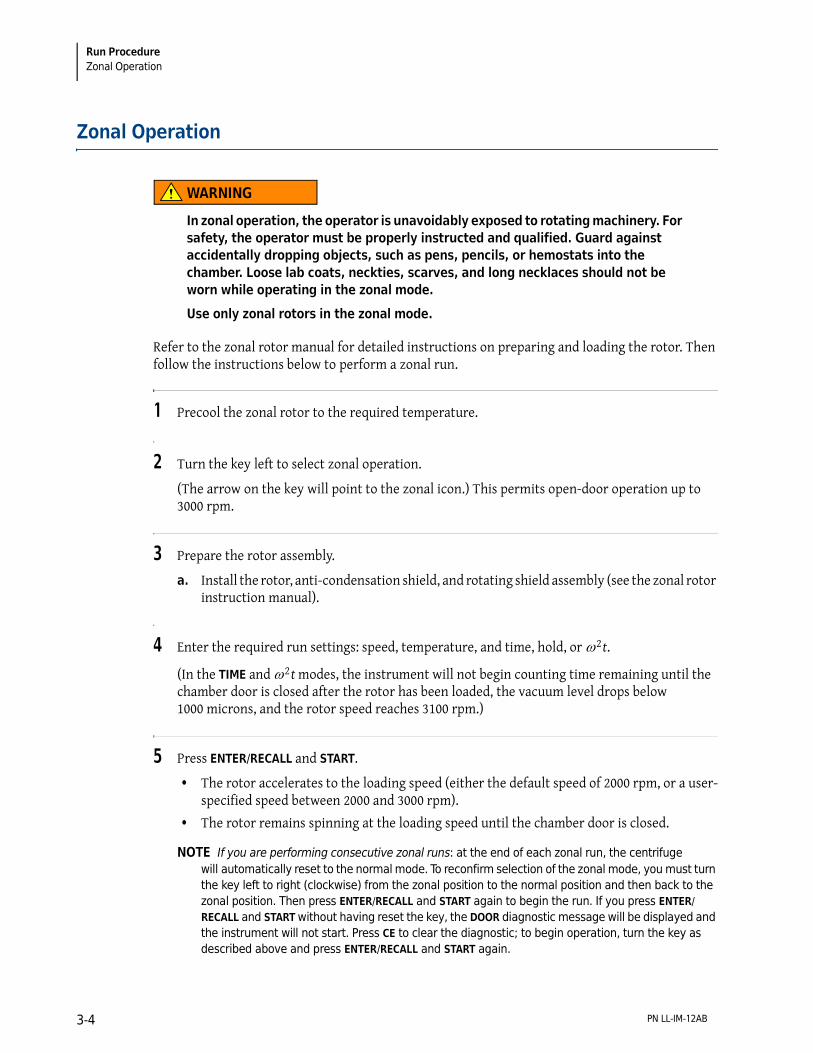
Zonal Operation
WARNING
In zonal operation, the operator is unavoidably exposed to rotating machinery. For safety, the operator must be properly instructed and qualified. Guard against accidentally dropping objects, such as pens, pencils, or hemostats into the chamber. Loose lab coats, neckties, scarves, and long necklaces should not be worn while operating in the zonal mode.
Use only zonal rotors in the zonal mode.
Refer to the zonal rotor manual for detailed instructions on preparing and loading the rotor. Then follow the instructions below to perform a zonal run.
1 Precool the zonal rotor to the required temperature.
2 Turn the key left to select zonal operation.
(The arrow on the key will point to the zonal icon.) This permits open-door operation up to 3000 rpm.
3 Prepare the rotor assembly.
a. Install the rotor, anti-condensation shield, and rotating shield assembly (see the zonal rotor instruction manual).
4 Enter the required run settings: speed, temperature, and time, hold, or ω2t.
(In the TIME and ω2t modes, the instrument will not begin counting time remaining until the chamber door is closed after the rotor has been loaded, the vacuum level drops below 1000 microns, and the rotor speed reaches 3100 rpm.)
5 Press ENTER/RECALL and START.
• The rotor accelerates to the loading speed (either the default speed of 2000 rpm, or a user-specified speed between 2000 and 3000 rpm).
• The rotor remains spinning at the loading speed until the chamber door is closed.
NOTE If you are performing consecutive zonal runs: at the end of each zonal run, the centrifuge will automatically reset to the normal mode. To reconfirm selection of the zonal mode, you must turn the key left to right (clockwise) from the zonal position to the normal position and then back to the zonal position. Then press ENTER/RECALL and START again to begin the run. If you press ENTER/RECALL and START without having reset the key, the DOOR diagnostic message will be displayed and the instrument will not start. Press CE to clear the diagnostic; to begin operation, turn the key as described above and press ENTER/RECALL and START again.
PN LL-IM-12AB3-4

Run ProcedureZonal Operation 3
6 Load the rotor.
7 Disconnect the seal assembly and cap the rotor.
Acceleration
8 Close the chamber door.
• The vacuum system will activate automatically.
• The rotor will hold at 3000 rpm until the chamber pressure drops below 750 microns, at which time it will accelerate to set speed and the instrument will begin counting time remaining or time lapsed.
Deceleration
9 When the run is ended (time remaining at zero, ω2t value reached, or STOP pressed), the rotor decelerates to 2000 rpm.
a. To abort a zonal run in progress, press STOP.
b. When the rotor speed decelerates to 2000 rpm, press STOP again.
10 When the SPEED setting indicates that the rotor is spinning at 2000 rpm, a series of beeps will sound.
a. Press VACUUM to vent the chamber.
b. Then open the chamber door.
Unloading
11 Unload the rotor according to the instructions in the zonal rotor manual.
a. Press STOP after unloading to bring the rotor to rest.
b. Keep the door closed between runs to help keep the chamber clean and dry.
NOTE When the rotor is at rest, the instrument will automatically reset to the Normal mode.
PN LL-IM-12AB 3-5

Run ProcedurePoints to Remember
Points to Remember
• Keep the chamber door closed whenever possible. This helps to keep the chamber clean, as well as assuring optimum performance of the vacuum system.
• For fast temperature equilibration, cool or warm the rotor to the required temperature before the run.
• Refer to the applicable rotor manual for complete instructions on rotor preparation, use, and care.
• Refer to CHAPTER 4, Troubleshooting and Maintenance if a diagnostic message flashes on the control panel during the run.
PN LL-IM-12AB3-6
CHAPTER 4
Troubleshootingand Maintenance
Introduction
This section lists possible malfunctions, together with probable causes and corrective actions. Maintenance procedures are also described. For any problems not covered here, contact Beckman Coulter Field Service for assistance.
NOTE It is your responsibility to decontaminate the instrument, as well as any rotors and/or accessories, before requesting service by Beckman Coulter Field Service.
In Case of Power Failure During Run
If a power failure occurs during the run, the rotor begins to decelerate with the brake off. If the rotor is spinning above 1000 rpm when power is restored, the instrument will resume operation and the rotor will return to set speed with maximum acceleration. A PWR diagnostic message will appear to alert you that a power outage occurred.
If the rotor is spinning below 1000 rpm or has stopped when the power is restored, the run automatically restarts. If the instrument is in the TIME mode, it will automatically reset the TIME display to the original set time. In the HOLD mode, the instrument will return to set speed and elapsed time will begin to accumulate again from zero. A PWR diagnostic message will appear to alert you that a power outage occurred and that the run has been restarted automatically.
Retrieving Your Sample
If a power failure lasts for several hours, it may be necessary to retrieve your sample from the rotor. (A rotor decelerating without the brake may take hours to come to a complete stop.) To gain access to the rotor chamber under these circumstances, you will need to remove the control head cover and the front panel to disengage the door lock.
PN LL-IM-12AB 4-1

Troubleshooting and MaintenanceRetrieving Your Sample
WARNING
Any maintenance procedure requiring removal of a panel exposes the operator to the possibility of electrical shock and/or mechanical injury. Therefore, turn the power OFF and disconnect the instrument from the main power source by removing the Mains (power) plug from the outlet receptacle, and refer such maintenance to service personnel.
WARNING
The following procedure should be implemented only when absolutely necessary and only by qualified service personnel.
1 Locate the two metal latches (see Figure 4.1) at the lower outside corners on the back of the control head.
a. Use your fingers to depress the latches to disengage the cover from the control head.
b. Then with both hands, slide the control head cover towards you until it is free.
c. Set the cover aside in a safe place.
Figure 4.1 Removing the Control Head Cover
1. Cover Latch2. Remove Key3. Access to Cover Latch
1
2
3
PN LL-IM-12AB4-2

Troubleshooting and MaintenanceRetrieving Your Sample 4
2 To open the top cover, insert a #2 (0.25-inch diameter) Phillips-head screwdriver into the hole located in the front, center of the top cover (see Figure 4.2).
a. Turn the screwdriver counterclockwise (to the left) until the screw bottoms out.
b. Then, to release the latch, push the screwdriver inward.
c. Once the latch is released, lift the top cover.
Figure 4.2 Depressing the Latch to Loosen the Front Panel
3 Vent the vacuum chamber by slowly turning the screw on the vacuum solenoid valve to the right until you hear the air released into the chamber.
If you hear a whining noise, close the valve and wait, as the rotor is still spinning.
4 About 10 seconds after the hissing noise stops, turn the screw to the left until it stops.
WARNING
NEVER try to slow or stop the rotor by hand.
1. Top Panel Tabs2. Front Panel Access Port3. Front Panel Tabs
ENTER/RECALL
7 8 9
4 5 6
1 2 3
0 CE
VACUUM
START
STOP
SPEED
TIME
TEMP
2
1
3
PN LL-IM-12AB 4-3

Troubleshooting and MaintenanceRetrieving Your Sample
5 Lift the front panel to free the bottom tabs that secure the panel in place.
WARNING
After removing the panel, listen carefully for any sounds coming from the drive. Then touch the fan housing (Figure 4.3) to feel if it is vibrating and listen again. Do not proceed if any sound or vibration is emitted from the housing.
6 Push down on the interlock pin (Figure 4.3) with your finger while opening the chamber door with your free hand.
a. (If the rotor is still spinning, close the door and wait.)
Figure 4.3 Interior View of Instrument (Door Removed)
7 After retrieving your sample, return the front panel to the instrument.
a. To do so, insert the tabs at the bottom of the front panel onto the lip at the base of the instrument, being sure to align the front panel with the side panels.
1. Spring-loaded Interlock Pin2. Door Lock System3. Vacuum Solenoid
4. Screw5. Fan Housing
1
2
3
4
5
PN LL-IM-12AB4-4

Troubleshooting and MaintenanceDiagnostic Messages 4
8 Lift the front edge of the top panel a few inches and insert the upper edge of the front panel under it.
a. Push down gently to engage the tabs.
9 Replace the control head by sliding it along the small ridges provided, making sure to clear the emergency POWER OFF switch in front.
a. When the control head cover is correctly positioned, push it until the latches snap shut and the cover is aligned with the rest of the instrument panels.
WARNING
Do not attempt to run the instrument before returning the front panel to its correct position.
Diagnostic Messages
Diagnostic messages appear as red LEDs at the left side of the upper display (see Figure 4.4) to alert you to conditions that may need your attention. A tone will sound and the appropriate message will blink until you press the CE key. The diagnostic messages will reappear if you attempt to restart the instrument and the problem has not been corrected.
Figure 4.4 Location of Diagnostic Messages on the Control Panel
1. Diagnostic Messages
VACUUM–µ
SPEED–RPM TIME–HR:MIN TEMP–°C
POWER OFF X 10,000
SAVE PROG HOLD w2t DECEL ACCEL
VACUUM
START
STOP
TIME
TEMP
CE 0
1 2 3
4 5 6
7 8 9 SPEED
ENTER/RECALL
SPEEDIMBAL
TEMPDOOR
DRIVEPWR
VACCPU
1
PN LL-IM-12AB 4-5
Troubleshooting and MaintenanceDiagnostic Messages
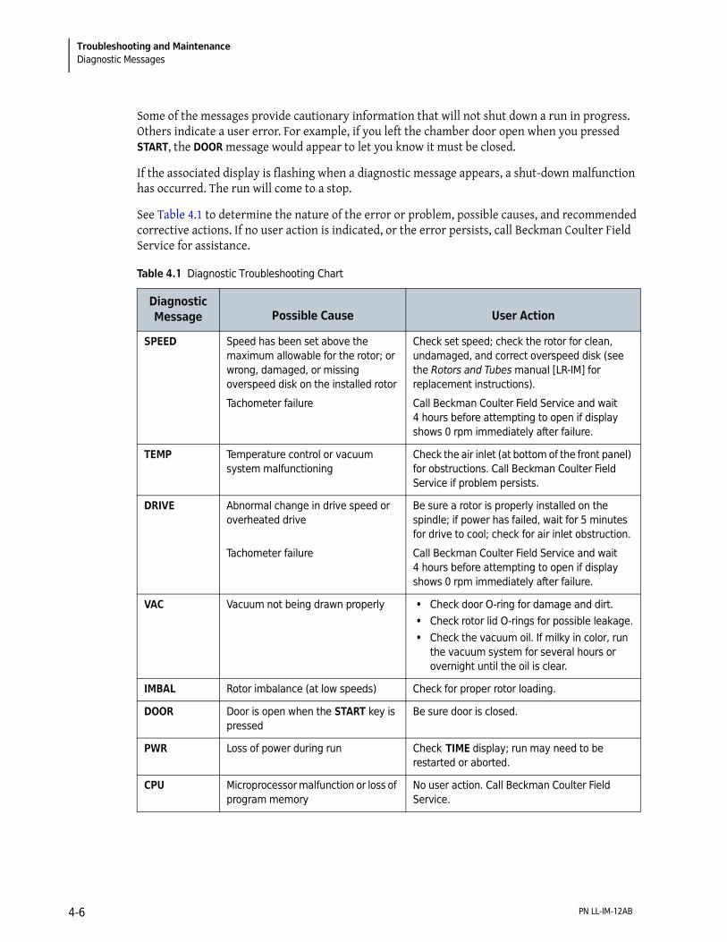
Some of the messages provide cautionary information that will not shut down a run in progress. Others indicate a user error. For example, if you left the chamber door open when you pressed START, the DOOR message would appear to let you know it must be closed.
If the associated display is flashing when a diagnostic message appears, a shut-down malfunction has occurred. The run will come to a stop.
See Table 4.1 to determine the nature of the error or problem, possible causes, and recommended corrective actions. If no user action is indicated, or the error persists, call Beckman Coulter Field Service for assistance.
Table 4.1 Diagnostic Troubleshooting Chart
Diagnostic Message Possible Cause User Action
SPEED Speed has been set above the maximum allowable for the rotor; or wrong, damaged, or missing overspeed disk on the installed rotor
Tachometer failure
Check set speed; check the rotor for clean, undamaged, and correct overspeed disk (see the Rotors and Tubes manual [LR-IM] for replacement instructions).
Call Beckman Coulter Field Service and wait 4 hours before attempting to open if display shows 0 rpm immediately after failure.
TEMP Temperature control or vacuum system malfunctioning
Check the air inlet (at bottom of the front panel) for obstructions. Call Beckman Coulter Field Service if problem persists.
DRIVE Abnormal change in drive speed or overheated drive
Tachometer failure
Be sure a rotor is properly installed on the spindle; if power has failed, wait for 5 minutes for drive to cool; check for air inlet obstruction.
Call Beckman Coulter Field Service and wait 4 hours before attempting to open if display shows 0 rpm immediately after failure.
VAC Vacuum not being drawn properly • Check door O-ring for damage and dirt. • Check rotor lid O-rings for possible leakage. • Check the vacuum oil. If milky in color, run
the vacuum system for several hours or overnight until the oil is clear.
IMBAL Rotor imbalance (at low speeds) Check for proper rotor loading.
DOOR Door is open when the START key is pressed
Be sure door is closed.
PWR Loss of power during run Check TIME display; run may need to be restarted or aborted.
CPU Microprocessor malfunction or loss of program memory
No user action. Call Beckman Coulter Field Service.
PN LL-IM-12AB4-6

Troubleshooting and MaintenanceCleaning 4
Cleaning
NOTE Before using any cleaning or decontamination methods except those recommended by the manufacturer, users should check with the manufacturer that the proposed method will not damage the equipment.
1 Keep instrument surfaces clean by wiping them with a cloth dampened with a mild detergent such as Solution 555.
a. Dilute the detergent with water (10 parts water to 1 part detergent).
b. If salts or other corrosive materials are used, however, or if spillage occurs, wash all affected areas immediately.
c. Do not allow corrosive materials to dry on the instrument.
d. (Be careful not to spill liquid on the instrument where electrical or mechanical components could get damaged.)
2 Keep the chamber door closed between runs to prevent moisture and dirt from collecting inside.
a. Wipe off the chamber walls with a dry cloth before each run.
Decontamination
If the instrument and/or accessories are contaminated with radioactive or pathogenic solutions, follow appropriate decontamination procedures as determined by your laboratory safety officer. Refer to Chemical Resistances (publication IN-175), or contact Beckman Coulter Field Service to ensure that the decontamination method does not damage any part of the instrument (or accessories).
Sterilization and Disinfection
The top working surface is finished with urethane paint; the sides are finished with general purpose paint. Ethanol (70%) may be used on both these surfaces. See publication IN-175 for more information regarding chemical resistance of instrument and accessory materials.
PN LL-IM-12AB 4-7

Troubleshooting and MaintenanceStorage and Transportation
CAUTION
Ethanol is a flammability hazard. Do not use it in or near operating ultracentrifuges.
While Beckman Coulter has tested these methods and found that they do not damage the instrument, no guarantee of sterility or disinfection is expressed or implied. When sterilization or disinfection is a concern, consult your laboratory safety officer regarding proper methods to use.
Storage and Transportation
Contact Beckman Coulter Field Service for specific instructions and/or assistance in preparing the instrument for transport or long-term storage. Temperature and humidity requirements for storage should meet the environmental requirements described under Specifications at the front of this manual.
Supply List
Call Beckman Coulter Sales (1-800-742-2345 in the United States) or your local Beckman Coulter office, or refer to Ultracentrifuge Rotors, Tubes, & Accessories catalog (BR-8101, available at www.beckmancoulter.com) for information on ordering parts, supplies, rotors, and accessories. A partial list of supplies is given below for your convenience.
NOTE For MSDS information, go to the Beckman Coulter website at www.beckmancoulter.com.
Description Part Number
Silicone vacuum grease (1 oz) 335148
Solution 555 (1 qt) 339555
Chamber O-ring 801778
Logbook for preparative ultracentrifuges 330049
Master rotor logbook 339587
Direct-drive vacuum pump oil 341661
Diffusion pump oil 330246
PN LL-IM-12AB4-8

Beckman Coulter, Inc.Optima L, LE, L-XP, and XL Preparative
Ultracentrifuges Warranty
Subject to the exceptions and upon the conditions specified below, Beckman Coulter, Inc., agrees to correct, either by repair, or, at its election, by replacement, any defects of material or workmanship which develop within one (1) year after delivery of the Optima Ultracentrifuge (the product), to the original Buyer by Beckman Coulter, or by an authorized representative, provided that investigation and factory inspection by Beckman Coulter discloses that such defect developed under normal and proper use.
Some components and accessories by their nature are not intended to and will not function for as long as one (1) year. If any such component or accessory fails to give reasonable service for a reasonable period of time, Beckman Coulter will repair or, at its election, replace such component or accessory. What constitutes either reasonable service and a reasonable period of time shall be determined solely by Beckman Coulter.
ReplacementAny product claimed to be defective must, if requested by Beckman Coulter be returned to the factory, transportation charges prepaid, and will be returned to Buyer with the transportation charges collect unless the product is found to be defective, in which case Beckman Coulter will pay all transportation charges.
Beckman Coulter makes no warranty concerning products or accessories not manufactured by it. In the event of failure of any such product or accessory, Beckman Coulter will give reasonable assistance to the Buyer in obtaining from the respective manufacturer whatever adjustment is reasonable in light of the manufacturer’s own warranty.
Damage to the instrument while operating a rotor not of Beckman Coulter manufacture is not covered by warranty or service contract terms. Further, Beckman Coulter shall be released from all obligations under all warranties either expressed or implied, if the product covered hereby is repaired or modified by persons other than its own authorized service personnel, unless such repair is made by others who meet qualifications similar to those required of Beckman Coulter’s service personnel, or unless such repair in the sole opinion of Beckman Coulter is minor, or unless such modification is merely the installation of a new Beckman Coulter plug-in component for such product.
Special Drive WarrantyDuring the instrument warranty period (one year), there will be no charge for drive replacement if the drive unit is installed, serviced, and operated in accordance with the conditions listed below. During the drive’s second through tenth year of use there is a prorated drive replacement price based on years of use if the drive unit is installed, serviced, and operated in accordance with the conditions listed below.
Drive replacement price for units not under service contract* = current drive exchange price
* For details of drive coverage with a service contract, contact your local Beckman Coulter service representative.
∞years of use
10----------------------------⟨ ⟩ labor and travel.+
PN LL-IM-12AB Warranty-1

Beckman Coulter, Inc. Optima L, LE, L-XP, and XL Preparative Ultracentrifuges Warranty
Conditions
1. The drive has been operated only within its rated speed and temperature ranges.
2. The drive unit has not been subjected to unequal loading, improper rotor installation, corrosion from material spilled onto the hub or accumulated in the chamber of the instrument.
3. The drive unit has not been disassembled, modified, or repaired, except by Beckman Coulter personnel.
4. The drive unit was installed by a Beckman Coulter Field Service representative.
5. The instrument in which the drive unit has been used and operated, and its associated rotors, were manufactured by Beckman Coulter and serviced only by Beckman Coulter Field Service representatives.
If the above conditions are not met, the full appropriate exchange price for the drive will be charged.
DisclaimerIT IS EXPRESSLY AGREED THAT THE ABOVE WARRANTY SHALL BE IN LIEU OF ALL WARRANTIES OF FITNESS AND OF THE WARRANTY OF MERCHANTABILITY AND THAT BECKMAN COULTER, INC. SHALL HAVE NO LIABILITY FOR SPECIAL OR CONSEQUENTIAL DAMAGES OF ANY KIND WHATSO-EVER ARISING OUT OF THE MANUFACTURE, USE, SALE, HANDLING, REPAIR, MAINTENANCE, OR REPLACEMENT OF THE PRODUCT.
PN LL-IM-12ABWarranty-2

English / Deutsch / Español / Français / Italiano / Portugués / Русский / 中文 / 日本語 / �국어
Symbol
Symbol
Simbolo
Symbole
Simbolo
Simbole
символ
符号
記号
상징
Title / Titel / Titulo / Titre / Titolo / Titulo / Название / 标题 / タイトル / 제목
Dangerous voltage
Gefährliche electrische Spannung
Voltaje peligroso
Courant haute tension
Pericolo: alta tensione
Tensão perigosaОпасное напряжение тока
危险电压危険な電圧위�� 전압
Caution, consult accompanying documents
Vorsicht, konsultieren Begleitdokumente
Atención, consulta documentos adjuntos
Attention, consultent des documents
d'accompagnement
Attenzione, consulta i documenti di
accompagnamento
Cuidado, ulta documentos adjuntos
Внимание, советует с сопроводительными
документами
注意, 咨询附属单证
注意, 伴う文書に相談しなさい
주의, 동반 문서를 상담.십시오
Biohazard
Potentiell infektiösem Material
Riesgo biológico
Risque biologiqu
Pericolo biologico
Material infeccioso potencial
биологической опасности
可能的传染性物潜在的な感染性物質전염.는 물자
On (power)
Ein (Netzverbindung)
Encendido
Marche (mise sous tension)
Acceso (sotto tensione)
Fora (o poder)
На (мощности)
开 B电源Dン B電源D에 (H)
Off (power)
Aus (Netzverbindung)
Apagado
Arrêt (mise sous tension)
Spento (fuori tensione)
Fora de (poder)
С (сила)B电源Dン B電源D떨어져 (H)
Protective earth (ground)
Schutzleiteranschluß
Puesta a tierra de protección
Liaison à la terre
Collegamento di protezione a terra
Terra de proteção (terra)
Защитное заземление (земля)
保护接地保護アース B接地D방어적인 지구 (지상)
Earth (ground)
Erde (Masse)
La tierra (suelo)
Terre (sol)
Scarica a terra
Terra
Земли
接地アース B接地D지구 (지상)
Manufacturer
Hersteller
Fabricante
Fabricant
Fabbricante
Fabricante
производитель
制造商メーカー제조자
Consult Instructions for Use
Konsultieren Sie Anwendungsvorschriften
Consulte las instrucciones para el uso
Consultez les instructions pour l'usage
Consulti le istruzioni per uso
Consulte instruções para o uso
Советуйте с инструкциями для пользы
咨询使用说明书使用説明に相談しなさい사용 설명을 상담.십시오

© 2013 Beckman Coulter, Inc.
All Rights Reserved
www.beckmancoulter.com
Related Documents
Rotors & Tubes for
Beckman Coulter Preparative
Ultracentrifuges
PN LR-IM-24 • Rotors • Tubes, Bottles, and
Accessories • Using Tubes, Bottles, and
Accessories • Using Fixed-Angle Rotors • Using Swinging-Bucket
Rotors • Using Vertical-Tube and
Near-Vertical Tube rotors • Care and Maintenance • Chemical Resistances • Using the w2t Integrator • The Use of Cesium
Chloride Curves • Gradient Materials • References • Glossary
Available in electronic pdf or CD-ROM by request.
Chemical Resistances for
Beckman Coulter
Centrifugation Products
PN IN-175
Available at www.beckmancoulter.com; also available in hardcopy or electronic pdf by request.