INSTRUCTIONS FOR USE - Krell Industries · S–1000 Surround Preamp/Processor Instructions for Use...
72
INSTRUCTIONS FOR USE S –1000 SURROUND PREAMP/PROCESSOR Owner’s Reference
Transcript of INSTRUCTIONS FOR USE - Krell Industries · S–1000 Surround Preamp/Processor Instructions for Use...

INSTRUCTIONS FOR USE
S–1000 SURROUND PREAMP/PROCESSOR
Owner’s Reference

S–1000Surround Preamp/ProcessorInstructions for Usev 07.0
Krell Industries, Inc.45 Connair RoadOrange, CT 06477-3650 USA
TEL 203-298-4000FAX 203-891-2028E-MAIL [email protected] http://www.krellonline.com
© 2007 by Krell Industries, Inc. All rights reserved. P/N 309958
DTS Digital Surround ™ is a discrete 5.1 channel digital audio format available on CD, LD, and DVD software which consequently cannot be decoded andplayed back inside most CD, LD, or DVD players. For this reason, when DTS-encoded software is played back through the analog outputs of the CD, LD,or DVD player, excessive noise will be exhibited. To avoid possible damage to the audio system, proper precautions should be taken by the consumer ifthe analog outputs are connected directly to an amplification system. To enjoy DTS Digital Surround ™ playback, an external 5.1 channel DTS DigitalSurround ™ decoder system must be connected to the digital output (S/PDIF, AES/EBU, or TosLink) of the CD, LD, or DVD player.
This product is manufactured in the United States of America. Krell® is a registered trademark of Krell Industries, Inc., and is restricted for use by KrellIndustries, Inc., its subsidiaries, and authorized agents. Krell Smart System Setup™ is a trademark of Krell Industries, Inc. “DTS”, “DTS Digital Surround”,“DTS ES Extended Surround”, and “Neo:6” are registered trademarks of Digital Theater Systems, Inc. TosLink is a trademark of Toshiba Corporation.Manufactured under license from Dolby Laboratories. "Dolby," "Pro Logic," and the double-D symbol are trademarks of Dolby Laboratories. ConfidentialUnpublished Works. Copyright 1992–1997 Dolby Laboratories, Inc. All rights reserved. HDMI, the HDMI logo and High-Definition Multimedia Interface aretrademarks or registered trademarks of HDMI Licensing LLC. All other trademarks and trade names are registered to their respective companies.
CONTACTINFORMATION
This product complies with theEMC directive (89/336/EEC)and the low-voltage directive(73/23/EEC).
IMPORTANT SAFETY INSTRUCTIONS1. Read Instructions.
2. Keep these Instructions.
3. Heed all Warnings.
4. Follow all Instructions.
5. Do not use this apparatus near water.
6. Clean only with dry cloth.
7. Do not install near any heat sources such as radiators, heat registers,stoves, or other apparatus (including amplifiers) that produce heat.
8. Unplug this apparatus during lightning storms or when unused for longperiods of time.
9. Refer all servicing to qualified service personnel. Servicing is requiredwhen the apparatus has been damaged in any way, such as a power-supply cord or plug is damaged, liquid has been spilled or objects havefallen into the apparatus, the apparatus has been exposed to rain ormoisture, does not operate normally, or has been dropped.
10. The S–1000 must be placed on a firm, level surface where it is notexposed to dripping or splashing.
11. The ventilation grids on the top and bottom of the S–1000 must beunobstructed at all times during operation. Do not place flammablematerial above or beneath the preamplifier.
12. Before making connections to the S–1000, ensure that the power is offand other components are in mute or stand-by mode. Make sure all cableterminations are of the highest quality, free from frayed ends, short circuits,or cold solder joints.
13. THERE ARE NO USER SERVICEABLE PARTS INSIDE THE S–1000 SUR-ROUND PREAMP/ PROCESSOR.
Please contact Krell if you have questions not addressed in this guide.

Contents
Krell S–1000 iii
INTRODUCTION 1
DEFINITION OF TERMS 2
UNPACKING 4
PLACEMENT 5
AC Power Guidelines 5
GETTING STARTED 6
FRONT PANEL DESCRIPTION 8
REMOTE CONTROL DESCRIPTION 13Battery Installation and Removal 13
BACK PANEL DESCRIPTION 16
CONNECTING THE S–1000 TO YOUR SYSTEM 19First: Connect Analog and Digital Sources 19
Next: Connect Video Sources 20Last: Connect Amplifiers and Sources 21
OVERVIEW: SYSTEM CONFIGURATION AND NAVIGATION 22Configuration Steps 22
Navigation Conventions 23
SYSTEM CONFIGURATION 24Accessing the Main Menu 24Step 1: Configure Loudspeakers 25Step 2: Configure Devices 30
Step 3: Configure Level Adjustment 39Step 4: Operation 47
SAVING AND RECALLING CUSTOMIZED SETTINGS AND RESTORING THE FACTORY DEFAULT SYSTEM SETTINGS 57
OPERATING THE S–1000 58
On/Off/Stand-by 68Tape Input and Output 58Simulcast 59
APPENDIX: OPERATING MODES FOR THE S–1000 60
Automatically Detected Modes 60User Selectable Modes 61
WARRANTY 63
RETURN AUTHORIZATION PROCEDURE 65
SPECIFICATIONS 66-67
Page

iv Krell S–1000
FIGURE 1 The S–1000 Front Panel 7
FIGURE 2 The S–1000 Remote Control 7
FIGURE 5 The S–1000 Back Panel 14
TABLE 1 S–1000 Connections and Corresponding Factory Default Decoding Modes, by Device 14
TABLE 2 Krell Music Surround Modes for the S–1000 62
Illustrations
Tables
Page
Page

Krell S–1000 1
Thank you for your purchase of the Krell S–1000 Surround Preamp/Processor.
The S–1000 serves as the centerpiece in a Krell HEAT™—High EndAudio Theater—system, which applies the fundamental principles ofKrell engineering to the creation of a fully integrated high-perfor-mance multi-channel sound system. The S–1000 delivers outstand-ing music and cinema soundtrack reproduction through the use of afull complement of advanced Krell technologies including discreteClass A, direct-coupled circuitry with balanced outputs, user-config-urable input assignment, and broadcast-quality video circuitry fea-turing HDMI™ technology.
The S–1000 features Dolby Digital 5.1, Dolby Digital EX, DTS-ES 6.1,DTS NEO:6, and Dolby Pro Logic II processing, in addition to nineproprietary Krell Music Surround modes. This flexibility allowsupgrades to software via Flash memory for future surround soundformats and design enhancements.
The owner’s reference manual contains important information onplacement, installation, and operation of the Krell S–1000. Pleaseread this information carefully. A thorough understanding of thesedetails helps ensure satisfactory operation of, and long life for yourS–1000 and related system components.
Introduction

2 Krell S–1000
Following are the definitions of key terms used in your owner’s refer-ence manual:
BalancedA symmetrical input or output circuit that has equal impedance fromboth input terminals to a common ground reference point. Theindustry standard for professional and sound recording installations,balanced connections have 6 dB more gain than single-ended con-nections and allow the use of long interconnect cables. Balancedconnections are immune to induced noise from the system or theenvironment.
Single-endedA two-wire input or output circuit. Use care when using single-endedconnections as the ground connection is made last and broken first.Turn the system off prior to making or breaking single-ended con-nections. Single-ended connections are not recommended for con-nections requiring long cable runs.
OffWhen the power switch on the back panel is placed in the downposition and LEDs turn off, the component is off.
Stand-by ModeWhen the S–1000 is connected to AC power and the back panelpower switch is on, the power/stand-by LED (2) illuminates in red.This indicates that the component is in stand-by mode, a low powerconsumption status that keeps the audio and regulator circuits atidle. Krell recommends leaving the component in the stand-by modewhen it is not playing music.
Operational ModeWhen the component is in the stand-by mode, and you press thepower button/pre key (1) the power/stand-by LED illuminates inblue. The component is in the operational mode and is ready to playmusic.
Definition of Terms
INPUT AND OUTPUTCONNECTIONS
OPERATION

Krell S–1000 3
Krell HEATThe Krell term HEAT, or High End Audio Theater, is a design applica-tion incorporated into Krell components to enhance multi-channelhome entertainment systems. A Krell HEAT system is an integratedhome theater system consisting of a state-of-the-art Krell preamp/processor and matching amplifiers that reproduce two channel andmulti-channel sources with audiophile sound quality, placing theaudience in the middle of a lifelike environment.
HDMI™High Definition Multimedia Interface (HDMI™) is a digital connectionstandard designed to provide the highest possible uncompressedvideo and audio quality over a single cable and connector.
Composite VideoAn encoded video signal that transmits luminance (Y) and color (C)information on one wire.
S-VideoVideo signal that separately transmits the luminance (Y) and color (C)components of the video signal using one wire.
Component VideoA video signal that uses three wires to convey luminance (Y), redminus luminance (R-Y), and blue minus luminance (B-Y) signals.Component video signals may be interlaced or progressive.Progressive signals build screen content in one pass rather than thetwo passes required for standard (interlaced) video. Progressivetechnology eliminates motion artifacts and produces film-quality pic-tures. Both your source and video monitor must be equipped withprogressive video technology to realize this advantage.
YPbPr One way of designating color difference signals, in which:
Y = the luminance signalPb = blue minus luminance (B-Y) signalPr = red minus luminance (R-Y) signal
Definition of Terms, continued
TECHNOLOGY
VIDEO

Unpacking
4 Krell S–1000
Open the box and remove the top layer of foam. You see theseitems:
1 S–1000 Surround Preamp/processor
1 IEC connector (AC power) cord
1 S–1000 handheld remote control
1 CR2025 lithium battery
1 12 VDC output (12 V trigger) cable
1 packet containing the S–1000 Quick Setup Guideand the warranty registration card.
Carefully remove the S–1000 and accessories from the box.Remove the foam end caps and protective plastic wrap from thecomponent.
If any of these items are not included in the shipping box, please contactyour authorized Krell dealer, distributor, or Krell for assistance. Save allpacking materials. If you must ship your S–1000 in the future, repack theunit in its original packaging to prevent damage in transit. See ReturnAuthorization Procedure, on page 65.
Note

Krell S–1000 5
Before you install the S–1000 Surround Preamp/processor into yoursystem, review the following guidelines to choose the location forthe component. This will facilitate a clean, trouble-free installation.
The S–1000 does not require any type of special rack or cabinet forinstallation. For the dimensions of your S–1000 see Specifications,on pages 66-67.
The S–1000 requires at least two inches (5 cm) of clearance on eachside and at least two inches (5 cm) of clearance above and belowthe component to provide adequate ventilation. In addition, theS–1000 requires at least three inches (7 cm) of clearance betweenother connected components. For installations inside cabinetry,extra ventilation may be necessary.
The S–1000 has superb regulation and does not require a dedicatedAC circuit. Avoid connections through extension cords or multipleAC adapters. High quality 15 amp grounded AC strips are accept-able.
High quality AC line conditioners or filters may be used if they aregrounded and meet or exceed the unit’s power supply rating of 100 VA.
Use the S–1000 only with the power cord supplied.
Placement
AC POWER GUIDELINES

Getting Started
6 Krell S–1000
The S–1000 Surround Preamp/processor provides a variety of con-nection and operation options for outstanding music and cinemasoundtrack reproduction, and offers a high degree of flexibility via anon-screen menu system. To setup the S–1000 quickly:
1. Connect the S–1000 to the rest of the components in your sys-tem, using Figure 3 on page 14 and Table 1 on page 15 as aguide. Please note:
On Screen Display (OSD). The S–1000 has three OSD outputs:component, S-video, and composite. There is no OSD availablefrom the HDMI™ output.
To View the Setup Menu. Connect any of the OSD outputs onthe S–1000 to the appropriate input on your video display.Press the remote control menu key. The front panel displayreads MENU MODE and all OSD outputs activate simultaneously.Tune the video display input to match the selected OSD videoconnection.
2. Enter the setup menu. The MAIN MENU screen appears on the videodisplay.
3. Using the video display and the remote, select LISTENING ROOM
SETUP. The LISTENING ROOM SETUP screen appears.
4. Select SPEAKER SETUP. The SPEAKER SETUP screen appears. Scrollthrough the available options and select your loudspeaker setup.
5. Select SPEAKER DISTANCE and enter information about the placementof your loudspeakers relative to your listening position.
6. Select SPEAKER LEVEL and calibrate the volume of your loudspeak-ers.
After you have connected and configured the S–1000 and are famil-iar with its basic features, you are ready to play music. See Oper-ating the S–1000, on page 58.
IMPORTANT:ACCESSING THEON-SCREEN DISPLAY

REMOTE ONLYFUNCTIONS
28 Amp Key 29 Menu Key30 Prev Key31 Mute Key32 Enter Key33 Right Directional Key
All other functions on the remote control duplicate frontpanel functions.
The following keys are not active on the S–1000 remote:MAIN, Z2, THX
Note:6 The LD key on the remote
corresponds to the cabledevice button/LED (6) on the front panel.
DVD CABLE SAT VCR TV
CD TUNER AUX GAME TAPE/VCR2
POWER
RECALL
SAVE
BALANCE
CENTER
SURR/BACK
SUB
PRE AMP STEREO MODE 1 MODE 2 PRO LOGIC II
7 2421 20
19 15 16 17 182625 14
101112
2713 23221 3 4
8 965
2
Figure 1 The S–1000 Front Panel
Krell S –1000 7
FRONT PANEL AND REMOTEFUNCTIONS
11 Tuner Button/LED/Key12 Aux Button/LED
and Aux1 Key13 Game Button/LED
and Aux2 Key14 Tape/VCR2 Button/
LED/Key
PROCESSINGMODE 15 Stereo Button/LED/Key16 Mode 1 Button/LED/Key17 Mode 2 Button/LED/Key18 Pro Logic II
Button/LED/Key19 Preamp Button/LED/Key
BASIC OPERATION1 Power Button/Pre Key2 Power/Stand-by LED3 Infrared Sensor4 Infrared Emitter
INPUT DEVICE SELECTION 5 DVD Button/Key6 Cable Button/LD Key7 SAT Button/Key8 VCR Button/Key9 TV Button/Key
10 CD Button/Key
DISPLAY WINDOW20 Front Panel Display
INDIVIDUALIZEDCHANNEL TRIM21 Center Button/Key22 Surr/Back Button/
Rear Key23 Sub Button/Key24 Balance Button/Key
PROCESSORFUNCTIONS25 Save Button/Key26 Volume Knob27 Recall Button
HOW TO NAVIGATE IN THE MENU MODE
1 Press the menu key (29) to enter and exit the menumode from the operational mode.
2 Press the direction keys (33) to scroll from line to line,and to scroll through options within a line.
3 Press the enter key (32) to select and set an option.
4 Use the directional keys to scroll to the next line.
5 Press the prev key (30) to return to the previous screen.Press the pre key (1) to exit the menu mode and place the S–1000 in the stand-bymode.
Figure 2 The S–1000 Remote
28
33
1
32
21
6
11
16
17
24
5
10
19
15
29
30
148
18
12
7
22
31
23
9
13
26

Front Panel and Remote Control DescriptionSee Figures 1 and 2 on page 7
8 Krell S–1000
The S–1000 Surround Preamp/processor front panel and remotecontrol access power on and off; input, and processing mode selec-tion; monitoring and display of processor status; and balance andvolume control. For functions accessed only using the remote con-trol, see page 12.
1 Power Button/Pre KeyThe power button or pre key switches the S–1000 from stand-by to the operational mode.
2 Power/Stand-by LEDStand-by Mode. When the AC power cord is plugged into thewall, and the back panel power switch (58) is on, the LED illu-minates in red, indicating that the component is in the stand-by mode.
Operational Mode. When the power button or pre key (1) ispressed, the LED illuminates in blue, indicating that the com-ponent is in the operational mode.
3 Infrared SensorThe infrared sensor receives commands from the S–1000remote control. For proper remote control operation, make surethe infrared sensor is not covered or obstructed.
4 Infrared EmitterEmits the S–1000 remote operation code to a learning remote.See Program Remote, on page 51.
The S–1000 is equipped with ten input device selection buttons. Ifproperly configured, the S–1000 automatically engages the correctvideo and audio inputs when you press the device selection button.
5 DVD Button/Key Press this button or key to select the digital video disc device.
6 Cable Button/LD Key Press this button or key to select the laser disc device.
7 SAT Button/Key Press this button or key to select the satellite feed device.
8 VCR Button/Key Press this button or key to select the VCR device.
Basic Functions
FUNCTIONSButton = on front panelKey = on remote controlBlue LED illuminated = functionactive, except for power/stand-byLED which illuminates red whenin stand-by mode.
Input Device Selection

Krell S –1000 9
9 TV Button/KeyPress this button or key to select the television device.
10 CD Button/Key Press this button or key to select the compact disc device.
11 Tuner Button/Key Press this button or key to select the AM/FM tuner device.
12 Aux Button/Aux1 Key Press this button or key to select an auxiliary device, such asphono, tape, or an additional DVD, LD, CD, or VCR.
13 Game Button/Aux2 Key Press this button or key to select a game.
14 Tape/VCR2 Button/St Key Press this button or key to playback pre-recorded tapes. Youmay also use this button or key to compare the output signal ofan analog tape recorder to an audio source. See Tape Inputand Output, on page 58.
15 Stereo Button/LED/KeyPress this button to select stereo decoding. The blue LED illumi-nates when this feature is engaged.
16 Mode 1 Button/LED/M1 Key17 Mode 2 Button/LED/M2 Key
Use these buttons or keys to select available decoding modesfor incoming signals from an audio source, for example DOLBY PLII
MOVIE.
Mode 1. The default mode for a signal is always selected byMode 1. The S–1000 activates the default mode assigned in theconfigure devices menu. In the operational mode, use the mode 1button or M1 key (16) to view and select or reset the default cod-ing mode.
Mode 2. All modes that can be used for the incoming signal areautomatically stored in Mode 2. Use the mode 2 button or M2key (17) to scroll through these other modes in the display win-dow. The last mode displayed in Mode 2 is the selected mode.The S–1000 automatically selects the assigned mode for theavailable signal.
For information on decoding modes, see Table 1 on page 15, andAppendix: Decoding Modes for the S–1000, on page 60.
Front Panel Description, continued
Input Device SelectionButtons and LEDs, continued
Decoding Modes

10 Krell S–1000
18 Pro Logic II Button/LED/PL KeyPress this button or key to select the Dolby Pro Logic II modesfor Dolby Surround encoded material, including laser discs,videotapes, television broadcasts, and compact discs.
The Dolby Pro Logic II modes are selected automatically if Dolby Digitalsource material is encoded for Pro Logic. To turn off these modes,press the Pro Logic II button.
19 Preamp Button/LED/KeyPress this button or key to send the signal from an analog inputdirectly to the volume control with no digital processing, using theanalog stage of the preamp. This function can be used for com-ponents which have a high quality signal. See Assign AnalogAudio Inputs, on page 33, for information on assigning the ana-log input to one of the device buttons (DVD, CABLE, SAT, VCR, TV, CD,
TUNER, AUX, GAME, TAPE/VCR2).
This feature is only available with a signal from an analog input. If youattempt to use it with a signal from a digital input, The S–1000 on-screen and front panel display will read NOT ALLOWED.
20 Front Panel DisplayThe front panel window provides status messages for S–1000operations, including volume and balance level, decoding mode,and zone information. When a new device is selected, the physi-cal inputs are displayed. The display turns off after 60 secondsof inactivity.
Use the center, surr/back, and sub buttons or keys to make tempo-rary loudspeaker output adjustments of +/- 10 dB. These temporarychanges revert to 0 dB when a new device is selected or when thesystem is powered down. For more information, see ConfigureLevel Adjustment, on page 39.
21 Center Button/LED/KeyUse this button to adjust the center loudspeaker volume. Pressthe center button or key, then use the volume knob or up anddown directional keys (26) to make the adjustments.
Phantom Center. Press the center button or key twice to acti-vate. Press the center button twice again to deactivate. TheS–1000 generates a center channel for use when no centerchannel is used.
Front Panel Description, continued
Display Window
Individualized Channel Trim
Decoding Modes, continued
Note
Note

Front Panel Description, continued
Krell S–1000 11
22 Surr/Back Button/LED/Rear KeyPress the surr/back button or key, then use the direction or levelbuttons (28) to adjust the volume of the surround loudspeakers.The phrase SURROUND TRIM appears on the front panel display. Toadjust the back loudspeakers, press the surr/back button again.BACK appears on the front panel display. Then use the directionor level buttons to adjust the volume of the back loudspeakers.
23 Sub Button/LED/KeyPress the sub (subwoofer) button or key, then use the volumeknob or directional keys (26) to adjust the subwoofer loudspeak-er volume.
24 Balance Button/LED/Bal KeyUse this button or key to adjust to the main left/right loudspeak-er balance. Press the button or key, then use the volume knob orthe up and down directional keys (26) to adjust the balance.Balance levels show numerically on the front panel display (20).Balance may be adjusted in .5 dB increments, up to 6 dB. Thecenter position is displayed as BAL 0.
Balance level keys revert to their original function as volume levelcontrols after 3 seconds of inactivity.
25 Save ButtonPress and hold this button to save system configuration settings.The save button is also used in programming a learning remote.See Saving and Recalling Customized Settings andRestoring the Factory Default System Settings, on page 57,and Program Remote, on page 51.
26 Volume Knob/Directional KeysUse the volume knob or directional keys to scroll through menuselections, adjust the output for the entire system, and adjustbalance and volume levels for the center loudspeaker, sur-round/back loudspeakers, and subwoofer. Volume and balancelevels appear in the front panel display (20).
27 Recall ButtonUse this button retrieve your system’s saved settings or toreplace all system settings with factory default settings. SeeSaving and Recalling Customized Settings and Restoringthe Factory Default System Settings, on page 57.
Individual ChannelTrim, continued
Processor Functions

12 Krell S–1000
The S–1000 remote control uses one CR2025 lithium battery, whichis included with the shipment.
To open the battery compartment on the back of the remote control:
1. Place the remote face down on the table.
2. Use your thumbnail or a small jeweler’s or eyeglass screwdriverto move the small tab toward the center of the remote, whileusing your index fingernail or screwdriver to pull down gently onthe slot to the right of the tab. The battery compartment will slideout.
3. Place the battery, plus side up, in the battery tray.
4. Slide battery compartment back into the remote until you hear aclick.
The remote control is ready for operation.
Do not use a knife or other sharp objects to open the battery compartment;they will scratch the remote control finish.
Replace batteries when remote control function becomes intermittent.
Remove batteries if the remote control is not to be used for a long period oftime. Battery leakage can damage the remote control.
The S–1000 Surround Preamp/processor remote control providesaccess to IR controllable power amplifiers, accesses the systemconfiguration menu and on screen display (OSD), and a special keyto engage digital room EQ. Other functions on the remote controlduplicate front panel functions.
These keys are not active on the S–1000 remote control: MAIN, Z2, THX.
The LD key (6) on the remote corresponds to the cable button/LED (6) onthe front panel.
The following functions are only accessible from the front panel, and are notavailable on the remote control: RECALL, SAVE.
28 Amp Key (Power Amp Key)Use this key to operate IR controllable power amplifiers, such asall Krell Evolution amplifiers.
29 Menu KeyUse this key to access the setup menu and on-screen menudisplay.
Remote Control Only DescriptionSee Figure 2 on page 7
BATTERYINSTALLATIONAND REMOVAL
Notes
Notes
REMOTE ONLYFUNCTIONS

Front Panel Description, continued
Krell S–1000 13
30 Prev KeyUse this key to return to the previously displayed setup menuscreen.
31 Mute KeyUse this key to mute the S–1000 output. When this function isactive, VOLUME MUTE appears in the front panel display.
32 Enter KeyUse this key to accept setup menu selections, accept an inputdevice selection, or display current system conditions.
33 Directional KeysIN THE OPERATIONAL MODE
Right Directional Key. Use this key to engage the DigitalRoom Equalizer.
Up and Down Directional Keys. Use these keys to select EQmemory.
IN THE MENU MODE
All Directional Keys. Use all four directional keys to navigatethe on-screen menus.
Up and Down Directional Keys. Use these keys to adjust vol-ume, balance, and selective volume for the center loudspeaker,surround loudspeakers, and subwoofer.
REMOTE ONLY FUNCTIONS,continued

POWER
HDMI OUTHDMI 4HDMI 3HDMI 2HDMI 1
12VDC OUT12VDC
IN1 2 3 4 Processor
RC-5 IN
SBLSLCL
R SW SR SBR
50/60 Hz
RS-232
MADE IN USA
DIGITAL AUDIO
OUT
1 3
2 4
1 2 3 4
SBLSBRSLSRANALOG AUDIO OUTPUTS
COMPOSITE VIDEO
OSD
OUT31
2 4
S-VIDEO1 3
2 4
OUT
OSD
OSD
COMPONENT VIDEO
IN
PrPbY
3
PrPbY
1
2
MULTI-CHANNEL INPUTSL C SL SBL
R SW SR SBR
R C L SW
ANALOG AUDIO INPUTS
R L
NO USER SERVICEABLE PARTS INSIDE
L
R
1 2 3 4 5 6 7
TAPE
IN OUT
L
R
L
R
VCR
IN OUT
51 50 56 53 5247 46 49 48 55 58
42 36 41 43 4434 37 38 39 40 45 54593557
Figure 3 The S–1000 Back Panel
ANALOG AUDIO INPUTS AND OUTPUTS34 Balanced Analog
Audio Outputs35 Single-ended
Analog Audio Outputs36 Balanced Analog
Audio Inputs37 Tape In Left and Right38 Tape Out Left and Right39 VCR In Left and Right40 VCR Out Left and Right41 Single-ended
Analog Audio Inputs42 7.1 Audio Inputs
DIGITAL AUDIO INPUTS AND OUTPUTS43 Optical Digital Audio Inputs44 Coaxial Digital Audio Inputs45 Digital Audio Output
VIDEO INPUTS AND OUTPUTS46 S-video Outputs47 S-video Inputs48 Composite Video Outputs49 Composite Video Inputs50 Component Video Outputs51 Component Video Inputs52 HDMITM Output53 HDMITM Inputs
BACK PANEL REMOTE CONTROL CONNECTIONS
54 Comm Port RS-232 Remote Connector
55 RC-5 In56 12 VDC In and Out57 DB 25 Out
POWER CONNECTIONS
58 Back Panel Power Switch59 IEC Connector
14 Krell S–1000
BACK PANEL FUNCTIONS

DEVICE S–1000 CONNECTIONS FACTORY DEFAULT DECODING MODES
Digital Analog Digital AnalogVideo Audio Audio Dolby 2.0 Dolby 5.1 DTS 5.1 PCM
DVD Component 1 COAX 1 S1 Dolby D+ Dolby D 5.1 DTS 5.1 Dolby PLII Dolby PLIIDolby PLII Movie Movie Movie Movie
CABLE HDMITM 2 COAX 3 S4 Dolby D+ Dolby D 5.1 DTS 5.1 Dolby PLII Dolby PLIIDolby PLII Movie Movie Movie Movie
SAT HDMITM 1 OPT 1 S3 Dolby D+ Dolby D 5.1 DTS 5.1 Dolby PLII Dolby PLIIDolby PLII Movie Movie Movie Movie
VCR S-Video 2 Disabled VCR N/A N/A N/A N/A Dolby PLII Movie
TV Composite 1 COAX 2 S2 Dolby D+ N/A N/A N/A Dolby PLII Dolby PLII Movie Movie
CD Disabled Disabled B1 N/A N/A N/A N/A Preamp
TUNER Disabled Disabled S5 N/A N/A N/A N/A Preamp
AUX Disabled Disabled 7.1 N/A N/A N/A N/A N/A
GAME Component 2 OPT 2 S6 N/A Dolby D 5.1 DTS 5.1 Dolby PLII Preamp
TAPE Composite 3 Disabled Tape N/A N/A N/A N/A Preamp
Krell S–1000 15
TABLE 1 S–1000 Connections and Corresponding Factory Default Decoding Modes, by DeviceConnect the S–1000 to the rest of the components in your system, using this table as a guide.
When the S–1000 is in the operating mode, press the mode button or M1key (16) on the remote control to read the current processing mode in thefront panel display. Press the mode button or M2 key (17) to review and selectother available modes. See Decoding Modes, on page 9.
In the menu mode, Step 2, Configure Devices screens show availabledecoding modes, by device. For example, see Assign Digital AudioInputs, on page 34; DTS Control, on page 44; PLII Control, on page 45.
The Appendix: Decoding Modes for the S–1000, on page 60, shows allthe decoding modes for the S–1000, and includes a listing of Krell MusicSurround modes.
Notes

Back Panel DescriptionSee Figure 3 on page 14
16 Krell S–1000
The back panel of the S–1000 Surround Preamp/processor providesall audio and video input and output connections, remote controlinputs and outputs, power on and off, and power connection. Theback panel functions are described below.
34 Balanced Analog Audio OutputsThe S–1000 is equipped with eight balanced analog audio chan-nel outputs, with XLR connectors, for the left, center, subwoofer,surround left, surround right, back left, and back right.
35 Single-ended Analog Audio OutputsThe S–1000 is equipped with eight single-ended analog audiochannel outputs, with RCA connectors, for the left, center, right,subwoofer, surround left, surround right, back left, and back right.
36 Balanced Analog Audio InputsThe S–1000 is equipped with one set of balanced inputs withXLR connectors.
37 Tape In Left and RightThe S–1000 is equipped with one set of single-ended tapeinputs with RCA connectors.
38 Tape Out Left and RightThe S–1000 is equipped with one set of single-ended tape out-puts with RCA connectors.
39 VCR In Left and RightThe S–1000 is equipped with one set of single-ended inputswith RCA connectors, for a VCR audio source.
40 VCR Out Left and RightThe S–1000 is equipped with one set of single-ended outputswith RCA connectors, for a VCR audio source.
41 Single-ended Analog Audio InputsThe S–1000 is equipped with seven sets of single-ended inputswith RCA connectors.
42 7.1 Audio InputsThe S–1000 is equipped with eight single-ended 7.1 analog pass-through inputs for multichannel SACD and DVD audio devices.
43 Optical Digital Audio InputsThe S–1000 is equipped with four optical digital EIAJ inputs withTosLink connectors.
FUNCTIONS
Analog Audio Outputsand Inputs
Digital Audio Inputs and Outputs

Krell S–1000 17
44 Coaxial Digital Audio Inputs The S–1000 is equipped with four coaxial digital audio inputswith RCA connectors.
45 Digital Audio Outputs The S–1000 is equipped with one digital audio outputs: coaxialwith an RCA connector.
46 S-video Outputs The S–1000 is equipped with two S-video outputs with DIN con-nectors. The main S-video output (labeled OSD on back panel)includes on-screen display. For dubbing purposes, the secondS-video output does not include on-screen display.
47 S-video Inputs The S–1000 is equipped with four S-video inputs with DIN con-nectors.
48 Composite Video Outputs The S–1000 is equipped with two composite video outputs withRCA connectors. The main composite video output (labeledOSD on back panel) includes on-screen display. For dubbingpurposes, the second composite video output does not includeon-screen display.
49 Composite Video Inputs The S–1000 is equipped with four RCA composite video inputswith RCA connectors.
50 Component Video Outputs The S–1000 is equipped with one set of component video outputswith RCA connectors. Component video uses three wires, labeledY, Pr, and Pb on the back panel, to convey the video signal. Theseinputs are compatible with all wideband video sources.
On-screen display (OSD) is available for interlaced component video; itis not available for progressive component video.
51 Component Video Inputs The S–1000 is equipped with three sets of component videoinputs.
52 HDMI™ OutputThe S–1000 is equipped with one HDMI™ video output.
Back Panel Description, continued
Video Inputs and Outputs
Note
Digital Audio Inputs andOutputs, continued

Back Panel Description, continued
18 Krell S–1000
53 HDMI™ InputsThe S–1000 is equipped with four HDMI™ video inputs.
The S–1000 switches HDMI™ video only. Audio signal is not available viathe HDMI™ inputs. On screen display (OSD) is not available from theHDMI™ output. When an HDMI™ input is assigned to a device, and themenu key on the remote is pressed, the on screen menu is availablesimultaneously from composite, S-video, and component OSD outputs.
54 Comm Port RS-232 ConnectorThe S–1000 is equipped with an RS-232 communication port,which sends operational instructions directly to the S–1000using an external computer control system.
55 RC-5 InThe RC-5 input makes custom installation easy and secure byaccepting baseband RC-5 input commands from hardwiredremote controllers.
56 12 VDC In and OutThe S–1000 is equipped with four programmable 12 V outputsand one input. Each trigger sends a 12 V power on/off signal via a12 V trigger cable to other Krell components and to other devicesthat incorporate 12 V power on/off trigger input. Trigger 1 isenabled for all 10 devices.
When the S–1000 is in the operational mode and a trigger is enabled, the12 VDC Out provides 12 V of DC output. When the S–1000 is in thestand-by mode or off, or if a trigger is not enabled, the DC output is 0 V.
57 DB 25 OutThe S–1000 is equipped with a multi-channel audio output via aDB-25 connector. The DB-25 contains the output connectionsfor all the output channels (left, center, right, subwoofer, surroundleft, surround right, back left, and back right).
58 Back Panel Power SwitchUse this switch to change the S–1000 from off to stand-by.
59 IEC ConnectorThe S–1000 is equipped with a standard female IEC power con-nector, for use with the AC power cord.
Back Panel Remote Control Connections
Note
Note
Power Connections

First:Connect Analog and Digital Sources
FOLLOW THESE CONNECTION STEPS
Connecting the S–1000to Your System
Krell S–1000 19
This section provides information about connecting the S–1000 Sur-round Preamp/processor to analog and digital sources, video sources,and amplifiers. The S–1000 is equipped with balanced and single-ended inputs.
Krell recommends using balanced interconnect cables. Balancedinterconnect cables not only can minimize sonic loss but also areimmune to induced noise, especially for installations using longcables. Balanced connections have 6 dB more gain than single-ended connections. When level matching is critical, keep this speci-fication in mind. Krell recommends that you use balanced inputs forcomponents that will use the preamp mode.
Follow these steps to connect the S–1000 to your system. Refer toTABLE 1, on page 15, for more information on device connectionsand available decoding modes, including factory default decodingmodes:
1. Make sure all power sources and components are off before connecting inputs and outputs.
2. Neatly arrange and organize wiring to and from the S–1000 andall components. Separate AC wires from audio cables to preventhum or other unwanted noise from being introduced into thesystem.
3. Connect the right and left outputs of your source components tothe inputs on the S–1000.
Stereo analog input sources. The S–1000 is equipped withnine pairs of single-ended analog audio inputs (S-1 through S-7(41), tape (37), and VCR (39) via RCA connectors and one set ofbalanced analog audio inputs (36) via XLR connectors.
Multi-channel analog sources. (For example, multi-channelSACD and DVD audio players). Connect the outputs of yoursource component to the 7.1 inputs (42) on the back panel.
Digital audio sources. Connect the digital audio output ofyour source components to the digital inputs on the S–1000.The S–1000 is equipped with four coaxial digital audio inputs(44) via RCA connectors and four EIAJ optical digital inputs(43) via TosLink connectors.

IMPORTANT:ACCESSING THEON-SCREEN DISPLAY
20 Krell S–1000
4. Connect the video source outputs to the appropriate videoinputs on the S–1000.
Component video inputs. Use the component connection whenthe source device (DVD) and output device (TV) both featurecomponent connections. Component video signals use threewires that convey luminance (Y), red minus luminance [R – Y] (Pr),and blue minus luminance [B – Y] (Pb) signals. See the user man-uals included with these devices for more information. TheS–1000 is equipped with 4 sets of component video inputs (51).
S-video inputs. S-video cables transmit the color and lumi-nance components of the video signal separately. The S–1000 isequipped with 3 sets of S-video inputs (47).
Composite video inputs. The S–1000 is equipped with fourcomposite video inputs (49).
HDMI™ video inputs. The S–1000 is equipped with fourHDMI™ video inputs (53).
5. Connect the video outputs of the S–1000 to the inputs of yourvideo monitor and/or video recorder.
The S–1000 is equipped with one set of component video out-puts (50), two S-video outputs (46), two composite video out-puts (48), and one HDMI™ output.
S-video inputs can be seen only on S-video outputs. Composite inputscan be seen only on composite outputs. Component inputs can beseen only on component outputs.
On screen display (OSD). The S–1000 features one OSD out-put for each category of video connection: component, S-video, and composite. There is no OSD available from theHDMI™ output.
To view the setup menu. Connect any of the OSD outputs onthe S–1000 to the corresponding input on your video display.Press the remote control menu key (29). The front panel dis-play reads MENU MODE and all OSD outputs activate simultane-ously. Tune the video display input to match the selected OSDvideo connection.
Connecting the S–1000 to Your System, continued
Note
Next:Connect Video Sources

Krell S–1000 21
The S–1000 has balanced outputs with XLR connectors and single-ended outputs with RCA connectors. Both outputs are active at alltimes, allowing simultaneous connection to separate amplifiers.Connect only one of these output formats to a single amplifier.
6. Connect the outputs of the S–1000 to the input(s) of your poweramplifier(s).
7. Connect the AC power cord to the IEC connector (59) on theS–1000 and to the AC wall receptacle.
8. Move the back panel power switch (58) into the up (on) position.The red power/stand-by LED (2) on the front panel illuminates.The words PLEASE WAIT, INITIALIZING appear in the front panel display(20). When the initializing message disappears, the S–1000 isready to switch to the operational mode.
9. Use either the front panel power button or the remote con-trol pre key (1) to power on the S–1000. The blue power LED (2)on the front panel illuminates. The S–1000 is now in the opera-tional mode and ready to be configured.
Make sure that all source devices are off when you configure theS–1000.
Connecting the S–1000 to Your System, continued
IMPORTANT
Last:Connect Amplifiers and Sources

IMPORTANT:FOR BEST RESULTSFOLLOW THESE STEPS
Overview: System Configuration and Navigation
22 Krell S–1000
This section briefly outlines S–1000 Surround Preamp/processorconfiguration menus and introduces menu navigation features.
The easy-to-follow, step-by-step configuration menus let you set upyour S–1000 for optimum performance. Detailed instructions beginon page 24. Krell recommends that you configure your componentin the sequence outlined on the main menu screen:
1. LISTENING ROOM SETUP, see pages 24-29
The SPEAKER SETUP menu enables you to define the number andtype of loudspeakers in your system and allows you to select thebass range for each loudspeaker, control the subwoofer outputand set the crossover frequency.
The SPEAKER DISTANCE menu enables you to define the exact loca-tion of each loudspeaker in the system, so that the S–1000 cansynchronize the output to all loudspeakers, no matter where theyare located in the room.
The CALIBRATE VOLUME menu enables you to set the volume to areference level, to match the sensitivities of different loudspeak-ers and amplifiers in your system.
2. CONFIGURE DEVICES, see pages 30-38
The configure devices menu enables you to assign each deviceinputs and configure modes and triggers using the setup menusfor CONFIGURE VIDEO, CONFIGURE AUDIO, and CONFIGURE TRIGGER.
3. CONFIGURE LEVEL ADJUSTMENT, see pages 39-46
The configure level menu enables you to set master volumetrims for the components in your system. These fixed positive ornegative volume offsets maintains level matching while switchingbetween inputs with different output levels. The setup menus in-clude: DEVICE TRIM, ANALOG INPUT TRIM, MUSIC MODE SUB TRIM, DTS CONTROL
TRIM, PLII CONTROL TRIM, and MAXIMUM VOLUME LIMIT.
4. OPERATION, see pages 47-56
The operation menu enables you to select screen position anddisplay time for the on-screen display (OSD) using the OSD OPERA-
TION set up menu; enables you to set audio modes using theAUDIO OPERATION set up menu and configure the 7.1 input usingthe 7.1 INPUT SETUP menu; enables you to program a learningremote control using the PROGRAM REMOTE setup menu; enablesyou to display system information using the SYSTEM INFORMATION
setup menu; and enables you to adjust frequency responsethrough the ROOM EQ SETUP menu.
CONFIGURATIONSTEPS

NAVIGATIONCONVENTIONS
Overview: System Configuration and Navigation, continued
Krell S–1000 23
The remote control is the main input device for configuring theS–1000. For all menu mode options, use the following keys to navi-gate through the configuration menu screens:
29 Menu Key Press this key once to enter the configuration menu. The frontpanel display reads MENU MODE. The MAIN MENU screen appears.Press this key again to exit the configuration menu. The S–1000reverts to the operational mode.
33 Direction or Level KeysUse all four directional keys to navigate the on-screen menus.
32 Enter KeyPress this key once to select a highlighted item. Once an item isselected, use the direction or level keys (33) to scroll throughavailable options within a line. To select a highlighted optionwithin a line, press the enter key again.
30 Prev KeyPress this key once to return to the previous screen within theconfiguration menu.
1 Pre Key The power key for the S–1000 is marked: Pre on the remote. Inthe menu mode it is used to exit the configuration menu. Pressthis key once. The S–1000 reverts to the stand-by mode.
When a menu screen first appears, and there is a cursor blinking atone menu item, press the enter key (32) to select the menu item. Ifthe item is configurable, the entire selection blinks along with thecursor.
Then use the direction keys (33) to scroll through the options that areblinking. Press the enter key to set your selection. After you have setthe selection, the selection stops blinking and only the cursor at themenu item is blinking. Use the direction keys to move the cursor tothe next menu item.
To Select and EnterMenu Options

24 Krell S–1000
The S–1000 Surround Preamp/processor is shipped with factorydefault selections in the configuration menus. For correct operationand maximum performance, use the sequence starting below, on thispage, to configure the S–1000 through the interactive on-screenmenus. These menus are structured to guide you through the setupprocess for your loudspeakers and for each device in your surroundsound system.
Configure the S–1000 loudspeaker positions in the listening room first,then configure each source device connected to your system com-pletely, before configuring the next source device.
To save your new configuration menus, or revert to the factorydefaults, see Saving and Recalling Customized Settings, andRestoring the Factory System Settings, on page 57.
Press the menu key. The front panel display reads MENU MODE. TheMAIN MENU screen appears.
System Configuration
ACCESSING THE MAIN MENU
Main Menu Screen
HOW TO NAVIGATE IN THE MENU MODE
1 Press the menu key (29) to enter and exit the menu mode from the operational mode.
2 Press the direction keys (33) to scroll from line to line, and to scroll through options within a line.
3 Press the enter key (32) to select and set an option.
4 Use the directional keys to scroll to the next line.
5 Press the prev key (30) to return to the previous screen.
6 Press the pre key (1) to exit the menu mode and place the S–1000 in the stand-by mode.
Menu

Krell S–1000 25
System Configuration, continuedStep 1, Listening Room Setup
The first option on the main menu screen, LISTENING ROOM SETUP, letsyou define the number and type of loudspeakers in your system andselect the bass range for each loudspeaker. It also allows you tocontrol the subwoofer output and set the crossover frequency.
Select LISTENING ROOM SETUP, on the MAIN MENU. The SPEAKER MAIN MENU
screen appears.
Select CONFIGURE SPEAKERS. The SPEAKER SETUP screen appears. Usingthis screen, you can enable loudspeakers that are in your system inthe left column and select loudspeaker characteristics in the far rightcolumn.
STEP 1LISTENING ROOMSETUP
Speaker Main Menu Screen
Speaker Setup Screen
Configure Speakers
26 Krell S–1000
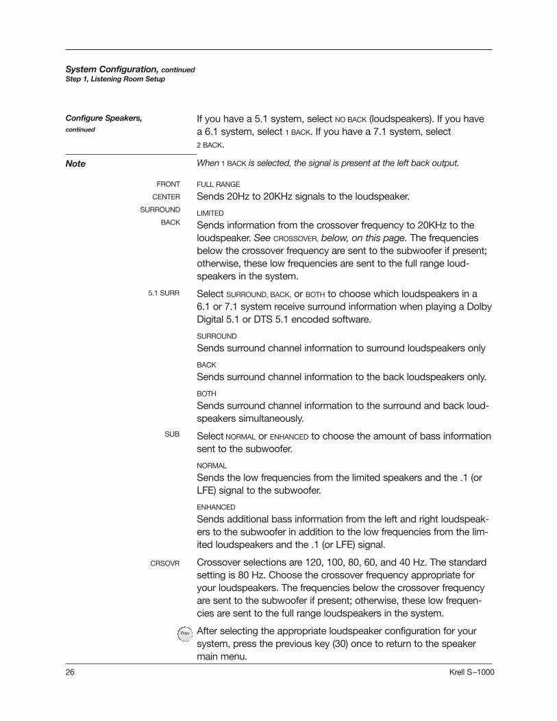
If you have a 5.1 system, select NO BACK (loudspeakers). If you havea 6.1 system, select 1 BACK. If you have a 7.1 system, select 2 BACK.
When 1 BACK is selected, the signal is present at the left back output.
FULL RANGE
Sends 20Hz to 20KHz signals to the loudspeaker.
LIMITED
Sends information from the crossover frequency to 20KHz to theloudspeaker. See CROSSOVER, below, on this page. The frequenciesbelow the crossover frequency are sent to the subwoofer if present;otherwise, these low frequencies are sent to the full range loud-speakers in the system.
Select SURROUND, BACK, or BOTH to choose which loudspeakers in a6.1 or 7.1 system receive surround information when playing a DolbyDigital 5.1 or DTS 5.1 encoded software.
SURROUND
Sends surround channel information to surround loudspeakers only
BACK
Sends surround channel information to the back loudspeakers only.
BOTH
Sends surround channel information to the surround and back loud-speakers simultaneously.
Select NORMAL or ENHANCED to choose the amount of bass informationsent to the subwoofer.
NORMAL
Sends the low frequencies from the limited speakers and the .1 (orLFE) signal to the subwoofer.
ENHANCED
Sends additional bass information from the left and right loudspeak-ers to the subwoofer in addition to the low frequencies from the lim-ited loudspeakers and the .1 (or LFE) signal.
Crossover selections are 120, 100, 80, 60, and 40 Hz. The standardsetting is 80 Hz. Choose the crossover frequency appropriate foryour loudspeakers. The frequencies below the crossover frequencyare sent to the subwoofer if present; otherwise, these low frequen-cies are sent to the full range loudspeakers in the system.
After selecting the appropriate loudspeaker configuration for yoursystem, press the previous key (30) once to return to the speakermain menu.
System Configuration, continuedStep 1, Listening Room Setup
Configure Speakers, continued
Note
FRONT
CENTER
SURROUND
BACK
5.1 SURR
SUB
CRSOVR
Prev

Krell S–1000 27
System Configuration, continuedStep 1, Listening Room Setup
The second option on the speaker main menu screen, SPEAKER DIS-
TANCE, allows you to tell the S–1000 the exact location of each loud-speaker in your system.
Select SPEAKER DISTANCE on the SPEAKER MAIN MENU. The ROOM SETUP
screen appears:
Speaker Distance
Room Setup Screen
When you access the ROOM SETUP screen, the cursor is blinking at theLEFT loudspeaker. Use the direction and enter keys to navigate thescreen, select loudspeakers, and enter the correct distance (0 to 30feet) from the main listen position to the loudspeaker.
After all the distances are set, press the previous key (30) once toreturn to the speaker main menu.
Any speaker not configured in the SPEAKER SETUP menu displays N/A (notavailable) on the ROOM SETUP screen.
Note
HOW TO NAVIGATE IN THE MENU MODE
1 Press the menu key (29) to enter and exit the menu mode from the operational mode.
2 Press the direction keys (33) to scroll from line to line, and to scroll through options within a line.
3 Press the enter key (32) to select and set an option.
4 Use the directional keys to scroll to the next line.
5 Press the prev key (30) to return to the previous screen.
6 Press the pre key (1) to exit the menu mode and place the S–1000 in the stand-by mode.
Prev

28 Krell S–1000
The third option on the speaker main menu screen, CALIBRATE VOLUME,
allows you to calibrate each channel using the internal noise genera-tor of the S–1000.
A sound pressure level (SPL) meter is required for this procedure.
Select CALIBRATE VOLUME on the MAIN MENU. The CALIBRATE ROOM SETUP
screen appears:
Press the enter key to choose AUTO NOISE SEQUENCE. The AUTO
CALIBRATION screen appears:
System Configuration, continuedStep 1, Listening Room Setup
Calibrate Room Setup Screen
Auto Noise Sequence
Auto Calibration Screen
Note
Calibrate Volume
HOW TO NAVIGATE IN THE MENU MODE
1 Press the menu key (29) to enter and exit the menu mode from the operational mode.
2 Press the direction keys (33) to scroll from line to line, and to scroll through options within a line.
3 Press the enter key (32) to select and set an option.
4 Use the directional keys to scroll to the next line.
5 Press the prev key (30) to return to the previous screen.
6 Press the pre key (1) to exit the menu mode and place the S–1000 in the stand-by mode.

Krell S–1000 29
Set the SPL meter to C weighting and slow response. After initializ-ing, the LEFT channel dB setting on the screen blinks, and you hearband limited white noise through the left loudspeaker. This noisecontinues for two seconds and then moves clockwise to the nextloudspeaker in the system.
While the individual channel on screen is blinking, use the directionkeys to adjust each loudspeaker’s setting until the SPL meter reads75 dB.
Repeat this process with the remaining loudspeakers. When all theloudspeakers are adjusted, press the previous key twice to return tothe main menu screen.
The adjustments must be made while the channel on screen is blinking.
Set the SPL meter to C weighting and slow response. After initializ-ing, the cursor at the LEFT channel dB setting on the screen blinks.Press enter. You hear banded white noise through the left loudspeak-er.
While the individual channel on screen is blinking, use the directionkeys to adjust each loudspeaker’s setting until the SPL meter reads75 dB.
Press enter to set each selection, then use the direction keys tomove to the next loudspeaker. Repeat this process for all loud-speakers.
Press the previous key twice to return to the main menu screen.
Any loudspeaker not configured in the SPEAKER SETUP menu displays N/A
(not available) for the dB specification.
The program material option uses the same screen as the automaticor manual noise sequence, but requires external program materialsuch as a test disc. The source plays, simultaneously, from all config-ured loudspeakers. Use the enter and direction keys to individuallyadjust loudspeaker levels based on your listening preferences ratherthan SPL readings. If all channels are not present in the source mate-rial, they will not be heard during this process.
System Configuration, continuedStep 1, Listening Room Setup
Manual Noise Sequence
Program MaterialOption
AUTO NOISE SEQUENCEcontinued
Note
Note
PrevPrev

IMPORTANT:PLEASE READ BEFORESTARTING STEP 2,CONFIGURE DEVICES
The S–1000 is shipped with pre-selected connections for eachdevice, as well as factory default decoding modes for analog anddigital inputs. See Table 1, on page 15.
To illustrate the method of selecting configuration options availablethrough the S–1000, Step 2, Configure Devices, uses one sourcedevice as an example: a DVD player. Configure each source deviceconnected to your system completely, before configuring the nextsource device, following the steps outlined in this manual. Audio fac-tory defaults for the S–1000 do not need to be configured if yoursystem matches the factory defaults.
Some S–1000 configurations are designed for digital only, and someare designed for analog only. If you try to format an analog sourcedevice using a digital configuration, the menu will not let you proceed.
IMPORTANT
30 Krell S–1000
System Configuration, continuedStep 2, Configure Devices
HOW TO NAVIGATE IN THE MENU MODE
1 Press the menu key (29) to enter and exit the menu mode from the operational mode.
2 Press the direction keys (33) to scroll from line to line, and to scroll through options within a line.
3 Press the enter key (32) to select and set an option.
4 Use the directional keys to scroll to the next line.
5 Press the prev key (30) to return to the previous screen.
6 Press the pre key (1) to exit the menu mode and place the S–1000 in the stand-by mode.

System Configuration, continued Step 2, Configure Devices
Krell S–1000 31
The second option on the main menu screen, CONFIGURE DEVICES,
allows you to assign video and audio inputs to source devices andconfigure triggers for devices in the system.
Select CONFIGURE DEVICES on the MAIN MENU. The CONFIGURE DEVICES
screen appears:
STEP 2CONFIGURE DEVICES
Configure Devices Screen
Assign Video Input Screen
Assign Video Input Select CONFIGURE VIDEO from the CONFIGURE DEVICES menu. The ASSIGN
VIDEO INPUT screen appears.
The ASSIGN VIDEO INPUT screen lets you select the device, configure it,and assign an input to the device.
assigned input=input on back panel

32 Krell S–1000
System Configuration, continuedStep 2, Configure Devices
PREVIOUS or DISABLED
For devices that do not use a video input, for example, a CD player,there are two options: PREVIOUS or DISABLED. PREVIOUS allows the lastactive video input to continue to be displayed, as long as a previousselection has been made. DISABLED turns off the video outputs.
NTSC or PAL
Choose a standard video format.
OFF, MENU ONLY, or MENU AND STATUS
Select one of these options for component video inputs, based onyour video source and monitor capabilities.
When using a progressive or high definition (HD) video source, selectOFF or MENU ONLY in order to pass the video signal properly. TheS–1000 can only display on-screen text in NTSC or PAL. If the moni-tor cannot automatically switch between progressive or HD videoand standard definition (NTSC or PAL) video, you must select OFF.Then, in addition, connect the composite or S-video OSD output tothe monitor, in order to disploay the setup menu.
HDMITM
Select this option for multi-channel output.
Use the enter (32) and directional (33) keys to navigate the menuand set selections.
When all selections are entered, press the previous key (30) once toreturn to the CONFIGURE DEVICES menu.
Assign Video Inputs, continued
HOW TO NAVIGATE IN THE MENU MODE
1 Press the menu key (29) to enter and exit the menu mode from the operational mode.
2 Press the direction keys (33) to scroll from line to line, and to scroll through options within a line.
3 Press the enter key (32) to select and set an option.
4 Use the directional keys to scroll to the next line.
5 Press the prev key (30) to return to the previous screen.
6 Press the pre key (1) to exit the menu mode and place the S–1000 in the stand-by mode.
Prev

Krell S–1000 33
Select ANALOG. The ASSIGN ANALOG AUDIO INPUT screen appears.
Use the direction and enter keys to scroll through and select thedevice you want to configure, select the MIGRATION/REC input, andchoose the analog mode, if mode options are available.
System Configuration, continued Step 2, Configure Devices
Assign Analog Audio Input Screen
Select CONFIGURE AUDIO from the CONFIGURE DEVICES menu. The ASSIGN
AUDIO INPUTS screen appears:Assign Analog AudioInputs
Assign Audio Inputs Screen

34 Krell S–1000
After the selections for analog audio inputs are entered, press theprevious key. The ASSIGN AUDIO INPUTS screen appears. Select DIGITAL.
The ASSIGN DIGITAL AUDIO INPUT screen appears.
Use the direction and enter keys to scroll through and select the dig-ital device you want to configure, select the digital input, and choosethe default mode for the four major surround sound digital formats:DOLBY DIGITAL 2.0, DOLBY DIGITAL 5.1, DTS 5.1, and PCM. You can choose adecoding preference for each of these signals under YOUR DECODE
PREFERENCE IS. For more information, see Decoding Modes for theS–1000, on page 60.
The digital input must be set to DISABLED to use the analog input.and it mustbe set to DISABLED to use preamp mode.
PREVIOUS holds the last selected digital input.
The DOLBY DIGITAL EX, DTS-ES DISCRETE 6.1, and DTS-EX MATRIX 6.1 operatingmodes are available only when your system has 6 or 7 channels.
When the device is configured, press the previous key (30) to returnto the ASSIGN AUDIO INPUTS menu.
System Configuration, continuedStep 2, Configure Devices
Assign Digital AudioInputs
Notes
Assign Digital Audio Input Screen
Assign Analog Audio Inputs, continued
AUTO-MIGRATION ON allows the S–1000 to switch to the analog inputautomatically, if no digital input is present. This function is particular-ly useful for SACD players.
The analog signal must be assigned, not DISABLED, in order for auto-migration to be active.
Prev

Krell S–1000 35
The lip synchronization screen allows you to add an adjustableamount of delay, from 0 to 200 ms, to the digital audio signal decod-ing process. LIP SYNC is used to synchronize a digital audio source(DVD, satellite, or cable decoder) with a display (LCD, plasma TV, orprojector), when the image is delayed by video processing in thedisplay.
Select LIP SYNCH from the assign audio inputs screen. The LIP SYNCH
DELAY screen appears.
Use the direction and enter keys to scroll through and select thedevice you want to configure for lip synchronization. Make sure thatthe device is already configured for the digital audio source and dis-play you intend to synchronize. Power on the source and display,and start playing a program.
Select DELAY and the delay time (0-200 ms). Select APPLY to hear theeffect. Continue to adjust the delay time and use the APPLY functionuntil you are satisfied with the synchronization.
When the device is configured, press the previous key (30) to returnto the ASSIGN AUDIO INPUTS menu.
System Configuration, continuedStep 2, Configure Devices
Assign Lip Synch Delay Screen
Assign Lip SynchDelay
Prev

36 Krell S–1000
The ASSIGN EQ MEMORY screen allows you to link any one of four EQmemories, or OFF, to any one of 10 devices. Once a link is made, theselected EQ memory loads automatically every time the device ischosen. For more information on Room EQ, see pages 53-56.
Select EQ MEMORY from the assign audio inputs screen. The ASSIGN
EQ MEMORY screen appears.
Use the direction and enter keys to scroll through and select thedevice to which you want to assign EQ memory. Select EQ memory1,2,3,or 4 or select OFF.
When the device is configured, press the previous key (30) twice toreturn to the CONFIGURE DEVICES menu.
System Configuration, continuedStep 2, Configure Devices
Assign EQ MemoryScreen
Assign EQ Memory
HOW TO NAVIGATE IN THE MENU MODE
1 Press the menu key (29) to enter and exit the menu mode from the operational mode.
2 Press the direction keys (33) to scroll from line to line, and to scroll through options within a line.
3 Press the enter key (32) to select and set an option.
4 Use the directional keys to scroll to the next line.
5 Press the prev key (30) to return to the previous screen.
6 Press the pre key (1) to exit the menu mode and place the S–1000 in the stand-by mode.
Prev

Krell S–1000 37
The final option on the CONFIGURE DEVICES menu is CONFIGURE TRIGGER.
This option allows you to customize the operation of the four remoteoutput 12 VDC (12 Volt trigger) connectors (54) on the back panel.
Select CONFIGURE TRIGGER from the CONFIGURE DEVICES menu. The CONFIGURE TRIGGER screen appears:
Use the direction and enter keys to select the source device.Select ALL TRIGGERS to configure all triggers at once, or chooseSELECTIVE to configure triggers individually. The delay is only avail-able when a trigger is set to ENABLED. There is a three second delayafter you select ENABLED, before the trigger turns on. The triggerturns off immediately when you select DISABLED.
ALL TRIGGERS
This option sets all 4 triggers on for all devices. When ALL TRIGGERS isactive, the selected mode and delay applies to all four triggers.
When the device is configured, press the previous key (30) twice toreturn to the MAIN MENU.
System Configuration, continuedStep 2, Configure Devices
Configure Trigger
Configure Trigger Screen
Prev

38 Krell S–1000
For each of the other devices available to your system (CABLE, SAT,
VCR, TV, CD, TUNER, AUX, GAME, or TAPE/VCR2), follow the procedure outlinedin Step 2, Configure Devices, pages 31-37. Configure each sourcedevice completely, before configuring the next source device.
When you have configured all the devices you want the S–1000 torecognize, press the previous button (74) twice to return to the mainmenu.
System Configuration, continuedStep 2, Configure Devices
Configuring AdditionalInputs
HOW TO NAVIGATE IN THE MENU MODE
1 Press the menu key (29) to enter and exit the menu mode from the operational mode.
2 Press the direction keys (33) to scroll from line to line, and to scroll through options within a line.
3 Press the enter key (32) to select and set an option.
4 Use the directional keys to scroll to the next line.
5 Press the prev key (30) to return to the previous screen.
6 Press the pre key (1) to exit the menu mode and place the S–1000 in the stand-by mode.
Note
Krell S–1000 39
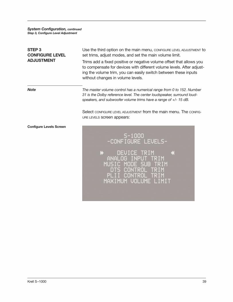
Use the third option on the main menu, CONFIGURE LEVEL ADJUSTMENT toset trims, adjust modes, and set the main volume limit.
Trims add a fixed positive or negative volume offset that allows youto compensate for devices with different volume levels. After adjust-ing the volume trim, you can easily switch between these inputswithout changes in volume levels.
The master volume control has a numerical range from 0 to 152. Number31 is the Dolby reference level. The center loudspeaker, surround loud-speakers, and subwoofer volume trims have a range of +/- 15 dB.
Select CONFIGURE LEVEL ADJUSTMENT from the main menu. The CONFIG-
URE LEVELS screen appears:
System Configuration, continued Step 3, Configure Level Adjustment
STEP 3CONFIGURE LEVELADJUSTMENT
Configure Levels Screen

40 Krell S–1000
The DEVICE TRIM is a master volume trim that is activated when aninput device is selected; it has a range of +/- 15 dB.
Select DEVICE TRIM from the CONFIGURE LEVELS menu. The DEVICE TRIM
screen appears:
Use the direction and enter keys to select the devices for which youwant to set trims, and the trim level for each.
When you have made your selections, press the previous key (30)once to return to the CONFIGURE LEVELS screen.
System Configuration, continued Step 3, Configure Level Adjustment
Device Trim
Device Trim Screen
HOW TO NAVIGATE IN THE MENU MODE
1 Press the menu key (29) to enter and exit the menu mode from the operational mode.
2 Press the direction keys (33) to scroll from line to line, and to scroll through options within a line.
3 Press the enter key (32) to select and set an option.
4 Use the directional keys to scroll to the next line.
5 Press the prev key (30) to return to the previous screen.
6 Press the pre key (1) to exit the menu mode and place the S–1000 in the stand-by mode.
Prev

Krell S–1000 41
System Configuration, continued Step 3, Configure Level Adjustment
An analog device must be selected in order for the analog input trimoption to function. The following screen appears if an analog deviceis not selected:
To select an analog device, first exit the menu program by pressingthe menu key (29). Then press the analog device key [for example,the tape key (14 )] on the remote control. The front panel displaysthe device selection. Enter the menu program and follow the proce-dure for selecting analog input trim described on the next page.
IMPORTANT:PLEASE READ BEFORECONFIGURING ANALOGINPUT TRIM
42 Krell S–1000
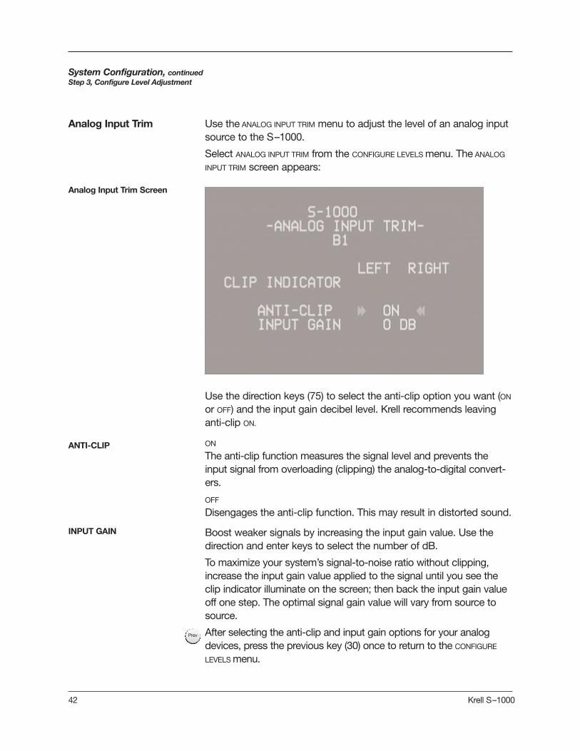
Use the direction keys (75) to select the anti-clip option you want (ON
or OFF) and the input gain decibel level. Krell recommends leavinganti-clip ON.
ON
The anti-clip function measures the signal level and prevents theinput signal from overloading (clipping) the analog-to-digital convert-ers.
OFF
Disengages the anti-clip function. This may result in distorted sound.
Boost weaker signals by increasing the input gain value. Use thedirection and enter keys to select the number of dB.
To maximize your system’s signal-to-noise ratio without clipping,increase the input gain value applied to the signal until you see theclip indicator illuminate on the screen; then back the input gain valueoff one step. The optimal signal gain value will vary from source tosource.
After selecting the anti-clip and input gain options for your analogdevices, press the previous key (30) once to return to the CONFIGURE
LEVELS menu.
System Configuration, continued Step 3, Configure Level Adjustment
ANTI-CLIP
INPUT GAIN
Use the ANALOG INPUT TRIM menu to adjust the level of an analog inputsource to the S–1000.
Select ANALOG INPUT TRIM from the CONFIGURE LEVELS menu. The ANALOG
INPUT TRIM screen appears:
Analog Input Trim
Analog Input Trim Screen
Prev

Krell S–1000 43
System Configuration, continued Step 3, Configure Level Adjustment
After setting the selection, press the previous key (30) once to returnto the CONFIGURE LEVELS menu screen.
Music Mode Sub Trim Screen
Music Mode Sub Trim Use the MUSIC MODE SUB TRIM menu to adjust the trim for the subwoofer,during music mode playback. The adjustment range is -10 to +10 dB.Music mode sub trim is active when using the PARTY, GENERAL ADMISSION,
FRONT ROW, ON STAGE, ENHANCED STEREO, ORCHESTRA, MEZZANINE, FULL RANGE +
SUB, and DTS NEO:6 modes.
Select MUSIC MODE SUB TRIM from the CONFIGURE LEVELS menu. The MUSIC
MODE SUB TRIM screen appears:
HOW TO NAVIGATE IN THE MENU MODE
1 Press the menu key (29) to enter and exit the menu mode from the operational mode.
2 Press the direction keys (33) to scroll from line to line, and to scroll through options within a line.
3 Press the enter key (32) to select and set an option.
4 Use the directional keys to scroll to the next line.
5 Press the prev key (30) to return to the previous screen.
6 Press the pre key (1) to exit the menu mode and place the S–1000 in the stand-by mode.
Prev

44 Krell S–1000
Use the DTS CONTROL menu to adjust the signal for DTS Neo:6 musicmode. The center gain adjusts the amount of center channel infor-mation present in the left and right loudspeakers. The adjustmentrange is 0 (no center channel information subtracted (wide soundfield) to 5 (maximum level of center channel information subtractedfrom the left and right channels (focused sound field).
Select DTS CONTROL TRIM from the configure levels menu. The DTS
CONTROL screen appears:
After setting the selection, press the previous key (30) once to returnto the CONFIGURE LEVELS screen.
DTS Neo:6 music mode derives a 6.0 signal from two-channel material. Formore information on DTS Neo:6 Modes, see User Selectable Modes onpage 61.
System Configuration, continued Step 3, Configure Level Adjustment
DTS Control Screen
DTS Control
HOW TO NAVIGATE IN THE MENU MODE
1 Press the menu key (29) to enter and exit the menu mode from the operational mode.
2 Press the direction keys (33) to scroll from line to line, and to scroll through options within a line.
3 Press the enter key (32) to select and set an option.
4 Use the directional keys to scroll to the next line.
5 Press the prev key (30) to return to the previous screen.
6 Press the pre key (1) to exit the menu mode and place the S–1000 in the stand-by mode.
Prev
Note
Krell S–1000 45
System Configuration, continued Step 3, Configure Level Adjustment
PLII Control Screen
After setting your selections, press the previous key (30) once toreturn to the CONFIGURE LEVELS screen.
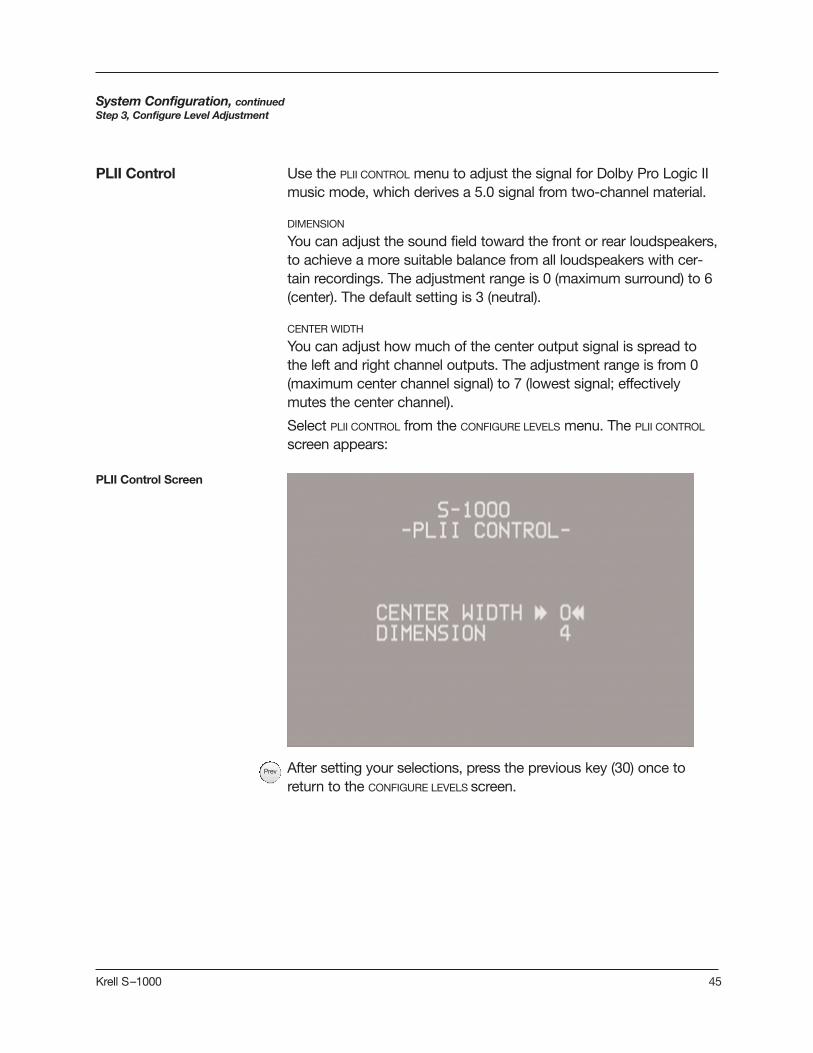
Use the PLII CONTROL menu to adjust the signal for Dolby Pro Logic IImusic mode, which derives a 5.0 signal from two-channel material.
DIMENSION
You can adjust the sound field toward the front or rear loudspeakers,to achieve a more suitable balance from all loudspeakers with cer-tain recordings. The adjustment range is 0 (maximum surround) to 6(center). The default setting is 3 (neutral).
CENTER WIDTH
You can adjust how much of the center output signal is spread tothe left and right channel outputs. The adjustment range is from 0(maximum center channel signal) to 7 (lowest signal; effectivelymutes the center channel).
Select PLII CONTROL from the CONFIGURE LEVELS menu. The PLII CONTROL
screen appears:
PLII Control
Prev

46 Krell S–1000
System Configuration, continued Step 3, Configure Level Adjustment
After setting your selection, press the previous key once to return tothe CONFIGURE LEVELS screen.
When MAXIMUM VOLUME LIMIT is set, Step 3, Configure Levels Adjust-ment, is complete. Press the previous key (30) twice to return to theMAIN MENU screen.
Maximum Volume LimitScreen
Use the MAXIMUM VOLUME LIMIT menu to set the maximum volume foryour system, from 0-152.
Select MAXIMUM VOLUME LIMIT from the CONFIGURE LEVELS menu. The MAXI-
MUM VOLUME LIMIT screen appears:
Maximum Volume Limit
HOW TO NAVIGATE IN THE MENU MODE
1 Press the menu key (29) to enter and exit the menu mode from the operational mode.
2 Press the direction keys (33) to scroll from line to line, and to scroll through options within a line.
3 Press the enter key (32) to select and set an option.
4 Use the directional keys to scroll to the next line.
5 Press the prev key (30) to return to the previous screen.
6 Press the pre key (1) to exit the menu mode and place the S–1000 in the stand-by mode.
PrevPrev

Krell S–1000 47
The final option on the main menu screen, OPERATION, lets you selectposition and display time for on-screen display (OSD), set audiooperation, program a learning remote control, adjust lip synchroniza-tion, and adjust frequency response using the Krell Digital RoomEqualizer.
Select OPERATION from the MAIN MENU. The OPERATION MENU screenappears, with the cursor blinking at OSD OPERATION:
Press enter to access the OSD OPERATION screen:
System Configuration, continuedStep 4, Operation
STEP 4 OPERATION
Operation Screen
OSD Operation Screen
OSD Operation

48 Krell S–1000
The on-screen display feature allows you to customize on-screendisplay options.
OSD ON TIME
Choose the number of seconds (0-10) that the on-screen displayinformation remains on the screen.
LINE NUMBER
Choose the location (from 1, top line, to 10, bottom line) at which theon-screen display appears.
After setting your selections, press the previous key (30) once toreturn to the OPERATION menu.
The next item in the OPERATION menu, AUDIO OPERATION, allows you tocustomize audio operation such as mute, mode holds, auto-switch-ing, and dynamic range.
Select AUDIO OPERATION from the OPERATION menu. The AUDIO OPERATION
screen appears:
Use the direction and enter keys to scroll through and select optionsfor audio operation:
MUTE MODE
The mute mode lets you select FULL mode in which the output iscompletely silenced or -20 dB in which the output is reduced by 20dB and may still be audible.
System Configuration, continuedStep 4, Operation
OSD Operation, continued
Audio Operation Screen
Audio Operation
HOW TO NAVIGATE IN THE MENU MODE
1 Press the menu key (29) to enter and exit the menu mode from the operational mode.
2 Press the direction keys (33) to scroll from line to line, and to scroll through options within a line.
3 Press the enter key (32) to select and set an option.
4 Use the directional keys to scroll to the next line.
5 Press the prev key (30) to return to the previous screen.
6 Press the pre key (1) to exit the menu mode and place the S–1000 in the stand-by mode.
Prev
Krell S–1000 49
DOLBY MODE HOLD
Dolby mode hold sets the time your S–1000 remains in DolbyDigital mode when the incoming bitstream is interrupted. Bitstreamsare interrupted in some devices when you press and release fastforward, track back/forward, or change channels for a compactdisc, video disc, or satellite receiver. The adjustment range is 0 (nohold) to 30 seconds.
DTS MODE HOLD
DTS mode hold sets the time your S–1000 remains in DTS modewhen the incoming bitstream is interrupted. Bitstreams are interrupt-ed in some devices when you press and release fast forward, trackback/forward, or change channels for a compact disc, video disc,or satellite receiver. The adjustment range is 0 (no hold)to 30 seconds.
EX AUTO SWITCHING
When ENABLED, the S–1000 will automatically engage Dolby DigitalSurround EX decoding if it receives a bitstream that is encoded inthis format. When this feature is DISABLED, you must manually selectDolby Digital Surround EX decoding.
DYNAMIC RANGE
Use the dynamic range screen to adjust the dynamic range of theS–1000. Options are:
NORMAL
11 dB of compression
MAX
no compression
NIGHT
22 dB of compression
After setting your selections, press the previous key (30) once toreturn to the OPERATION menu.
System Configuration, continuedStep 4, Operation
Audio Operation, continued
Prev

50 Krell S–1000
System Configuration, continuedStep 4, Operation
7.1 Input Setup Screen
ACTIVE INPUTS
Use the direction keys to find the input combination that matchesyour connections. Press enter to set the selection.
ACTIVE SW
Select YES if subwoofer is present and NO if it is not.
After setting your selections, press the previous key (30) once toreturn to the OPERATION menu.
The 7.1 INPUT SETUP menu allows you to select the 7.1 inputs that areconnected.
Select 7.1 INPUT SETUP from the OPERATION menu. The 7.1 INPUT SETUP
screen appears:
7.1 Input Setup
HOW TO NAVIGATE IN THE MENU MODE
1 Press the menu key (29) to enter and exit the menu mode from the operational mode.
2 Press the direction keys (33) to scroll from line to line, and to scroll through options within a line.
3 Press the enter key (32) to select and set an option.
4 Use the directional keys to scroll to the next line.
5 Press the prev key (30) to return to the previous screen.
6 Press the pre key (1) to exit the menu mode and place the S–1000 in the stand-by mode.
Prev

Krell S–1000 51
System Configuration, continuedStep 4, Operation
Program Remote Screen A
Program Remote Screen B
Program Remote The PROGRAM REMOTE menu allows you to program a learning remotecontrol to operate the S–1000.
The infrared sensor on the front panel is inactive until programming is com-plete.
Select PROGRAM REMOTE from the OPERATION menu. The first PROGRAM
REMOTE screen appears:
After you select START, the second PROGRAM REMOTE screen appears:
Note

52 Krell S–1000
System Configuration, continuedStep 4, Operation
Program Remote,continued
1. Rotate the knob (26) on the front panel to select a command.The command appears on the front panel display window (20).
2. Place the programmable remote in program mode (see the learn-ing remote user manual).
3. Place the infrared sensor of the programmable remote so that itfaces the infrared emitter (4) on the S–1000 front panel.
4. Press and hold the save button (25) on the S–1000 front paneluntil the programmable remote has learned the code (see thelearning remote user manual for information on the time neededto learn the code).
5. Select and save as many commands as desired.
6. To exit the program mode, press the recall button (27) on thefront panel to revert to Program Remote Screen A from ProgramRemote Screen B. Press the previous button (30) to return to theoperation menu from Program Remote Screen A.
The SYSTEM INFORMATION menu displays AC line frequency, the versionof software that your component is currently using, and informationabout the EEPROM.
Select SYSTEM INFORMATION from the OPERATION menu. The SYSTEM INFOR-
MATION screen appears:
System Information Screen
System Information
Prev
After reviewing the system information screen, press the previ-ous key (30) once to return to the operation menu.
Prev

IMPORTANT:PLEASE READ BEFORECONFIGURING ROOMEQ SETUP
System Configuration, continuedStep 4, Operation
ADJUSTABLE PARAMETERS
The Room EQ Setup accesses the Digital Room Equalizer, a featuredesigned by Krell to provide every adjustment from simple bass andtreble to comprehensive room correction. The Digital RoomEqualizer enables you to adjust frequency response through threediscrete bands (I, II, and III). The four adjustable parameters availableare filter type, frequency, shape, and level.
There are four Room EQ setup memories, each of which savesevery parameter set for every filter, for every channel. Each setupmemory can save a configuration, for example, one for stereomusic, one for multichannel music, one for movie surround, and onefor video game software.
You can adjust the filters for S–1000 channels globally or individual-ly. Up to three filters can be configured to act equally on all sevenchannels of audio. Alternatively, each filter can be configured sepa-rately for each individual channel.
TYPE
Six filter types are available for each filter: Notch Filter, Peaking Filter,High Shelf Filter, Low Shelf Filter, High Pass Filter (HPF) and LowPass Filter (LPF). Each of the filter types available has a uniqueeffect on frequency response.
The following three parameters for filters may be configured,depending on the filter type selected:
FREQ
The center/cutoff frequency can be specified for all six filter types,from 20 Hz to 16 kHz in 1/3 octave increments.
SHAPE
Shape controls the bandwidth of the filter and is adjustable on theNotch and Peaking filter types, from 0.4 to 9 octaves. Shape is fixedat a 6 dB / octave slope for the High and Low Pass Filters. Thisparameter is not available for the High and Low Shelf Filters.
LEVEL
Level is adjustable on the Peaking, High Shelf and Low Shelf filters,from -12 dB to +6 dB. Level is fixed for the Notch Filter at - 90 dB.This parameter is not available for the High and Low Pass Filters.
Krell S–1000 53
HOW TO NAVIGATE IN THE MENU MODE
1 Press the menu key (29) to enter and exit the menu mode from the operational mode.
2 Press the direction keys (33) to scroll from line to line, and to scroll through options within a line.
3 Press the enter key (32) to select and set an option.
4 Use the directional keys to scroll to the next line.
5 Press the prev key (30) to return to the previous screen.
6 Press the pre key (1) to exit the menu mode and place the S–1000 in the stand-by mode.

CHANNEL SELECTION
System Configuration, continuedStep 4, Operation
SAVING ROOM EQ SETUPMEMORY
USING ROOM EQ SETUP INTHE OPERATIONAL MODE
When the channel field is set to ALL, the ROOM EQ SETUP menu displaysthe filter settings which apply to all channels and all of the channelsare filtered in the same manner. When the channel parameter selec-tion is set to only one of the channels (L, C, R, LS, RS, LB, RB, S),the filter settings apply to each of the channels individually.
There are four selectable memories associated with the ROOM EQ
SETUP menu. Values are saved automatically when you enter a selec-tion.
Room EQ settings are stored in the S–1000 memory in the samemanner as all of the other software settings, for example the selec-tions for loudspeaker setup and device configuration. See Savingand Recalling Customized Settings and Restoring the FactoryDefault System Settings, on page 57, for more information.
When the S–1000 is in the operational mode, access the saved EQconfigurations by pressing the right directional key (33) on theremote. Use the up and down directional keys (26) to scan throughthe four memories and OFF.
54 Krell S–1000
The selection ALL overrides individually configured channels.IMPORTANT
APPLYING YOUR CONFIGURATIONS
Your configurations take effect only when you press enter in theAPPLY field. APPLY allows you to hear the effect of the selections youhave made without leaving the menu, if you have a source deviceplaying.
HOW TO NAVIGATE IN THE MENU MODE
1 Press the menu key (29) to enter and exit the menu mode from the operational mode.
2 Press the direction keys (33) to scroll from line to line, and to scroll through options within a line.
3 Press the enter key (32) to select and set an option.
4 Use the directional keys to scroll to the next line.
5 Press the prev key (30) to return to the previous screen.
6 Press the pre key (1) to exit the menu mode and place the S–1000 in the stand-by mode.

Krell S–1000 55
System Configuration, continuedStep 4, Operation
Room EQ Setup Screen
Room EQ Setup The final item on the OPERATION menu, ROOM EQ SETUP, allows you toadjust your loudspeaker to your listening area using the Krell DigitalRoom Equalizer. Select ROOM EQ SETUP from the OPERATION menu. TheROOM EQ SETUP screen appears, with the cursor blinking at OFF:
Use the direction and enter keys on the S–1000 remote control toscroll through and select the following step-by-step options foraudio operation:
MEMORY
Navigate to one of the four memory locations and enter your selec-tion. When MEMORY is set to OFF (the factory default), all of the filtersare disabled.
CHANNEL
Navigate to CHANNEL and select ALL to apply your configurations to allchannels at once or select any individual channel to apply your con-figurations to that channel. Enter your selection.
The selection ALL overrides individually configured channels.IMPORTANT

56 Krell S–1000
System Configuration, continuedStep 4, Operation
Room EQ Setupcontinued
Note
TYPE
Navigate to TYPE, and configure one, two, or all of the three bands(I, II, III) for FREQ, SHAPE, and LEVEL.
It is not necessary to configure all three filters, you may configure only oneor two filters.
Not all parameters are adjustable for all filter types.
APPLY
Select APPLY and set the selection, if you want to hear your configu-ration. The Room EQ Setup configurations you have just selectedaudible if you have a source device playing.
After selecting the appropriate loudspeaker configuration for yoursystem, press the previous key (30) twice to return to the main con-figuration menu.
Exit the main configuration menu by pressing the menu key (29) onthe remote. The S–1000 is now in the operational mode.
HOW TO NAVIGATE IN THE MENU MODE
1 Press the menu key (29) to enter and exit the menu mode from the operational mode.
2 Press the direction keys (33) to scroll from line to line, and to scroll through options within a line.
3 Press the enter key (32) to select and set an option.
4 Use the directional keys to scroll to the next line.
5 Press the prev key (30) to return to the previous screen.
6 Press the pre key (1) to exit the menu mode and place the S–1000 in the stand-by mode.
PrevPrev
Menu

Saving and Recalling Customized Settings andRestoring the Factory Default System Settings
Krell S-1000 57
To save the customized settings that you have entered, press andhold the save button (25) for approximately four seconds. The frontpanel displays SAVING SETUP while the settings are being stored in thenonvolatile memory of the S–1000 Surround Preamp/processor.
To retrieve your system’s saved settings, press and hold the recallbutton (27) for approximately four seconds. The front panel displaysRECALL SETUP while the settings are being retrieved from the non-volatile memory of the S–1000. Any settings that have been savedwill be available through recalling system setup.
To replace all system settings with the factory default settings, followthese steps:
1. Press the front panel power button or power pre key (1) to putyour system into the operational mode.
2. Simultaneously press the recall button (27) and the power button orpre key (1). The front panel first displays:
RECALL SETUP
and then the front panel displays:S–1000VERSION 1.060 HZ
Customized settings for the S–1000 revert to the factory default set-tings.
If you save your settings, they are still in memory after you restore the factorydefault system settings. Follow Recalling Customized Settings above toretrieve your customized settings.
SAVING CUSTOMIZED SETTINGS
RESTORING THE FACTORY DEFAULTSYSTEM SETTINGS
RECALLING CUSTOMIZEDSETTINGS
Note

Operating the S–1000
58 Krell S-1000
After the S–1000 Surround Preamp/Processor is connected tosource devices and amplifiers, and the system setup configured, theS–1000 is ready for operation.
1. Insert the AC power cord into the IEC connector (59) on theS–1000. Insert the other end into the AC wall receptacle.
2. Move the back panel power switch (58) into the up (on) position.
3. The red stand-by LED on the front panel illuminates. The wordsPLEASE WAIT, INITIALIZING appear in the front panel display (20). Whenthe initializing message disappears, the S–1000 is ready to bepowered on.
The front panel display shows volume, input information, andselected mode. After five seconds of inactivity, the displaybecomes blank.
4. Use either the front panel power button or power pre key (1) topower on the S–1000. The blue power LED (2) on the frontpanel illuminates. The S–1000 is now in the operational mode.
5. To return to stand-by, press the front panel power button orpower pre key again.
Krell recommends that the back panel power switch remain up (on) at alltimes.
The S–1000 has a discrete tape input and output. The tape outputis used to send an input signal from any analog input (S-1 through S-7, B-1, or VCR) to a recording device or processor.You can use the tape feature in three ways:
1. Use the tape input to playback pre-recorded tapes.
2. Use the tape input to compare the output signal of a three-headanalog tape recorder to the output signal of an audio source.Press the tape button or key (14) to switch between the taperecorder output (LED illuminated) and the input source (LED notilluminated).
ON/OFF/STAND-BY
TAPE INPUT AND OUTPUT
Note

Krell S–1000 59
Operating the S–1000, continued
Tape Input and Output, continued
Notes
3. Use the tape output to create a processor loop, when the S–1000is connected to a graphic equalizer or other ancillary equipment.Connect the equipment to the S–1000 tape outputs (34) asdescribed in the equipment manufacturer’s manual. Press the tapebutton (15) or key (64) to switch between the processor output(LED illuminated) and the input source (LED not illuminated).
The tape output functions only with analog sources.
There is no tape output from the 7.1 multi-channel input.
When changing sources, lower the volume to off or mute the output. Thisensures that the next source played does not damage your system with ahigh output transient.
When you are listening to or viewing different devices that have dif-ferent trigger settings (configured through the setup menus), you canretain a trigger setting using the previous (30) key.
For example, you have configured the S–1000 to turn on the TVmonitor when trigger 4 is on and the CD player is set for TRIGGER 4
OFF. You want to watch TV and listen to a CD at the same time. Ifyou press the TV button or key followed by the CD button or key,the TV monitor will turn off.
To keep the monitor on and turn on the CD player, follow thesesteps:
1. Press the TV button or key (9) to select the device. Begin playingthe device.
2. Press the prev key (30).
3. Press the CD button or key (10). Begin playing the device.
SIMULCAST

Appendix: Decoding Modes for the S–1000
60 Krell S–1000
The S–1000 Surround Preamp/processor automatically engages theappropriate decoding mode for the following signals:
DOLBY DIGITAL 2.0 OR DOLBY DIGITAL 2.0 + DOLBY PRO LOGIC
Select a Dolby Digital 2.0 or Dolby Digital 2.0 + Dolby Pro Logicdefault mode using the configuration menu. All modes listed underDolby Digital 2.0, including the default mode you have selected, canbe accessed using the mode 2 button or M2 key (17).
DOLBY DIGITAL 5.1
Select a Dolby Digital 5.1 default mode using the configuration menu.All modes listed under Dolby Digital 5.1, including the default modeyou have selected, can be accessed using mode 2 button or M2 key(17). .
DOLBY DIGITAL EX
Dolby Digital EX creates six full-bandwidth output channels from 5.1-channel sources. This is done using a matrix decoder thatderives three surround channels from the two in the original record-ing. For best results, Dolby Digital EX should be used with moviesoundtracks recorded with Dolby Digital Surround EX. All modes list-ed under Dolby Digital EX, including the default mode you haveselected, can be accessed using the mode 2 button or M2 key (17).
DTS 5.1
Select a DTS 5.1 default mode using the configuration menu. Allmodes listed under DTS 5.1, including the default mode you haveselected, can be accessed using the mode 2 button or M2 key (17).
DTS-ES DISCRETE 6.1
The S–1000 engages DTS-ES Discrete 6.1 decoding. All of the fol-lowing modes, plus DTS-ES DISCRETE 6.1 can be accessed using themode 2 button or M2 key (17) : DTS-ES MATRIX 6.1, DTS 5.1 MOVIE, and DTS
5.1 MUSIC.
DTS-ES MATRIX 6.1
The S–1000 engages DTS ES Matrix 6.1 decoding. The followingmodes plus DTS-ES MATRIX 6.1 can be accessed using the mode 2 but-ton or M2 key (17): DTS 5.1 MOVIE and DTS 5.1 MUSIC.
The DOLBY DIGITAL EX, DOLBY D 5.1, DTS-ES DISCRETE 6.1, and DTS-EX MATRIX 6.1
operating modes are available only when your system has 6 or 7 channels.
AUTOMATICALLYDETECTED MODES
Note

Appendix: Additional Decoding Modes for the S–1000, continued
User selectable modes available on the S–1000 are listed below:
Dolby Pro Logic II is the next generation in Dolby Surround decod-ing. The Pro Logic II decoder takes 2 channels in and 5 channelsout. It is designed specifically to decode all existing Dolby Surroundprograms with improved spatiality and directionality. Pro Logic II isalso designed for use with stereo music recordings that are notencoded. This feature draws the listener into a three-dimensionalspace rather than hearing a flat, two-dimensional presentation.
There are 4 modes in which the Pro Logic II decoder can operate:
DOLBY PLII MOVIE
The movie mode is the improved counterpart to the original ProLogic decoder. It is the choice for the majority of Dolby Surroundencoded material.
DOLBY PLII MUSIC
The music mode is for use with unencoded stereo music recordings.The music mode features dimension and center width controls, seePLII Control, on page 45, to enhance the music surround experience.
DOLBY PLII MATRIxThe matrix mode is useful for monaural recordings.
DOLBY PRO LOGIC
The Dolby Pro Logic mode provides the same surround processingas the original Pro Logic and is best used with source content that isnot of optimum quality.
DTS Neo:6 provides up to six full-bandwidth channels of informationfrom stereo encoded material. 7.1 and 6.1 systems will derive sixchannels from the signal while 5.1 systems will derive five channelsfrom the signal. DTS Neo:6 includes two modes: DTS NEO:6 CINEMA fortwo channel matrixed movie material and DTS NEO:6 MUSIC for stereoencoded music material.
USER SELECTABLEMODES
Dolby Pro Logic IIModes
Krell S–1000 61
DTS Neo:6 Modes

Appendix: Additional Decoding Modes for the S–1000, continued
62 Krell S–1000
Krell Music Surround Modes simulate different soundfield experienceswhen listening to music. The table below lists the modes and theloudspeakers that operate within each mode:
Krell Music SurroundModes
TABLE 6 Krell Music Surround Modesfor the S–1000
OPERATING MODES ACTIVE LOUDSPEAKERS
GENERAL ADMISSION L/R/S/RR
FRONT ROW L/R/S/RR
ON STAGE L/R/C/S/RR
ENHANCED STEREO L/R/C/S
ORCHESTRA L/R/C/S/RR
MEZZANINE L/R/C/S/RR
FULL RANGE + SUB L/R/C/S/RR
MONOPHONIC C/S
PARTY L/R/C/S/RR

Warranty
Krell S–1000 63
To register your product forwarranty benefits, pleasecomplete and return theWarranty Registration Cardenclosed in the shipping boxwithin 15 days of purchase.
Thank you.
Krell products have a limited warranty. Amplifiers, preamplifiers, pre-amp/ processors, and receivers carry a limited warranty of five yearsfor parts and labor on circuitry. Loudspeakers carry a limited warran-ty of five years for parts and labor. CD and DVD players carry a limit-ed warranty of five years for parts and labor on circuitry, and threeyears for parts and labor on mechanical parts.
Should the product fail to perform at any time during the warranty,Krell will repair it at no cost to the owner, except as set forth in thiswarranty.
This warranty does not apply to damage caused by acts of God ornature.
This warranty shall be in lieu of any other warranty, expressed orimplied, including, but not limited to, any implied warranty of mer-chantability or fitness for a particular purpose. There are no war-ranties which exceed beyond those described in this document, ifthe product does not perform as warranted herein, the owner’s soleremedy shall be repair. In no event will Krell be liable for incidental orconsequential damages arising from purchase, use, or inability touse the product, even if Krell has been advised of the possibility ofsuch damages.
Proof of purchase in the form of a bill of sale or receipted invoicesubstantiating that the product is within the warranty period must bepresented to obtain warranty service. The warranty begins on thedate of the original retail purchase, as noted on the bill of sale orreceipted invoice from an authorized Krell dealer or distributor.Previously owned equipment, when re-purchased from an autho-rized Krell dealer or distributor, has the balance of the original war-ranty, based on the original date of manufacture. Krell dealers anddistributors are not authorized to sell current products on theInternet. Current products purchased via the Internet do not haveany transferrable warranty.
The warranty for a Krell product is valid only in the country to whichit was originally shipped, through the authorized Krell distributor forthat country, and at the factory. There may be restrictions on orchanges to Krell’s warranty because of regulations within a specificcountry. Please check with your distributor for a complete under-standing of the warranty in your country.
If the product is serviced by a distributor who did not import theunit, there may be a charge for service, even if the product is withinthe warranty period.

64 Krell S–1000
Freight to the factory is your responsibility. Return freight within theUnited States (U.S.A.) is included in the warranty. If you have pur-chased your Krell product outside the U.S.A. and wish to have it ser-viced at the factory, all freight and associated charges to the factoryare your responsibility. Krell will pay return freight to the U.S.A.-based freight forwarder of your choice. Freight and other charges toship the product from the freight forwarder to you are also yourresponsibility.
Krell is not responsible for any damage incurred in transit. Krell willfile claims for damages as necessary for a product damaged in tran-sit to the factory. You are responsible for filing claims for shippingdamages during the return shipment.
Krell does not supply replacement parts and/or products to theowner of the product. Replacement parts and/or products will befurnished only to the distributor performing service on this producton an exchange basis only; any parts and/or products returned toKrell for exchange become the property of Krell.
No expressed or implied warranty is made for any Krell productdamaged by accident, abuse, misuse, natural or personal disaster,or unauthorized modification.
Any unauthorized voltage conversion, disassembly, componentreplacement, perforation of chassis, updates, or modificationsperformed to the product will void the warranty.
The operating voltage of the product is determined by the factoryand can only be changed by an authorized Krell distributor or at thefactory. The voltage for this product in the U.S.A. cannot bechanged until six months from the original purchase date.
In the event that Krell receives a product for warranty service thathas been modified in any way without Krell authorization, all war-ranties on that product will be void. The product will be returned tooriginal factory layout specifications at the owner’s expense before itis repaired. All repairs required after the product has been returnedto original factory specifications will be charged to the customer, atcurrent parts and labor rates.
All operational features, functions, and specifications and policiesare subject to change without notification.
Warranty, continued

Return Authorization Procedure
Krell S–1000 65
If you believe there is a problem with your component, please con-tact your dealer, distributor, or the Krell factory to discuss the prob-lem before you return the component for repair. To expedite service,you may wish to complete and e-mail the Service Request Form inthe Service section of our website.
Simply click on the Service Request Form in the navigation tier onthe Krell home page at http://www.krellonline.com
To return a product to Krell, please follow this procedure so that wemay serve you better:
1. Obtain a Return Authorization Number (R/A number) and ship-ping address from the Krell website.
2. Insure and accept all liability for loss or damage to the productduring shipment to the Krell factory and ensure all freight (ship-ping) charges are prepaid.
The product may also be hand delivered if arrangements with theService Department have been made in advance. Proof of purchasewill be required for warranty validation at the time of hand delivery.
Use the original packaging to ensure the safe transit of the product tothe factory, dealer, or distributor. Krell may, at its discretion, return aproduct in new packaging and bill the owner for such packaging if theproduct received by Krell was boxed in nonstandard packaging or ifthe original packaging was so damaged that it was unuseable. If Krelldetermines that new packaging is required, the owner will be notifiedbefore the product is returned.
To purchase additional packaging, please contact your authorizedKrell dealer, distributor, or the Krell Service Department.
Your S–1000 Surround Preamp/processor product serial number is:
HOW TO RETURNA PRODUCT
IMPORTANT
HOW TO PURCHASEADDITIONAL PACKING
TEL 203-298-4020Monday-Friday, 9:00 am to 5:00 pm EST
FAX 203-795-2287E-MAIL [email protected] http://www.krellonline.com
SERIAL NUMBER
HOW TO EXPEDITESERVICE
ACCESSING THESERVICE REQUESTFORM
TO CONTACT THEKRELL SERVICEDEPARTMENT

Specifications
66 Krell S–1000
OUTPUTS
REMOTE
DECODING MODES
INPUTS
SIGNAL-TO-NOISE RATIO
TOTAL HARMONICDISTORTION (THD)
"A" WEIGHTED 94 dB
UNWEIGHTED 20 Hz-20 kHz, -88 dB
ANALOG AUDIO 1 pair balanced via XLR connectors7 pairs single-ended via RCA connectors8 7.1 via RCA connectors
DIGITAL AUDIO 4 coaxial via RCA connectors4 EIAJ optical via TosLink connectors
VIDEO 4 S-video via DIN connectors4 composite via RCA connectors3 component via RCA connector
ANALOG TAPE 2 pair single-ended via RCA connectors
HDMITM 4 via HDMITM connectors
ANALOG CHANNEL 8 balanced via XLR connectors (one per channel) 8 single-ended via RCA connectors
ANALOG TAPE 1 pair single-ended via RCA connectors
DIGITAL 1 coaxial via RCA connector1 EIAJ optical via TosLink connectors
VIDEO 2 S-video via DIN connector, 1 with OSD2 composite via RCA connectors, 1 with OSD1 component via RCA connectors with OSD
HDMITM 1 via HDMITM connectors
REMOTE CONTROL 1 infrared
REMOTE CONNECTORS 1 RS-2321 RC-5 input4 12 VDC OUT (12 V trigger)1 12 VDC IN (12 V trigger)
Dolby Pro Logic IIDolby Digital 5.1Dolby Digital EXDTS 5.1DTS ES Discrete 6.1DTS ES Matrix 6.1DTS Neo:6

Specifications, continued
Krell S–1000 67
WEIGHT
SURROUND ENHANCEMENTMODES
DIMENSIONS
KRELL MUSIC SURROUND General AdmissionFront RowOn StageEnhanced StereoOrchestraMezzanineFull Range + SubMonophonicParty
35 W
INCHES 17.3w x 5.7h x 16.5d
CENTIMETERS 43.8w x 14.4h x 41.8d
SHIPPING 25 lb. 11.3 kg
UNIT ONLY 19.3 lb. 8.8 kg
All operational features, functions, specifications, and policies are subject to changewithout notification.
POWER CONSUMPTION

Krell Industries, Inc.45 Connair RoadOrange, CT 06477-3650 USA
TEL 203-298-4000FAX 203-891-2028E-MAIL [email protected] http://www.krellonline.com
SURROUND PREAMP/PROCESSORv 07.0
S–1000