INSTRUCTIONS FOR SAFE OPERATION AND MAINTENANCE · Per ANSI standard Z535.6-2011, the defi nitions...
24
©Copyright Task Force Tips, Inc. 2002-2014 LIX-630 September 5, 2014 Rev18 MANUAL: BLITZFIRE ® Portable Monitor Series INSTRUCTIONS FOR SAFE OPERATION AND MAINTENANCE DANGER Understand manual before use. Operation of this device without understanding the manual and receiving proper training is a misuse of this equipment. Obtain safety information at www.tft.com/serial-number DANGER Risk of sliding increases at low elevation angles. To reduce risk of injury or death from sliding, test safety shutoff valve before using. This Instruction Manual is intended to familiarize firefighters and maintenance personnel with the operation, servicing, and safety procedures associated with the portable monitor. This manual should be kept available to all operating and maintenance personnel. TASK FORCE TIPS, INC. MADE IN USA • www.tft.com 3701 Innovation Way, Valparaiso, IN 46383-9327 USA 800-348-2686 • 219-462-6161 • Fax 219-464-7155 MAXIMUM OPERATING PRESSURE 175 PSI (12 BAR) MAXIMUM FLOW 500 GPM (2000 LPM) blitzfire ® blitzfire ® osc BLITZFIRE MONITOR HIGH ELEVATION BLITZFIRE MONITOR BLITZFIRE OSCILLATING MONITOR HIGH ELEVATION BLITZFIRE OSCILLATING MONITOR
Transcript of INSTRUCTIONS FOR SAFE OPERATION AND MAINTENANCE · Per ANSI standard Z535.6-2011, the defi nitions...

©Copyright Task Force Tips, Inc. 2002-2014 LIX-630 September 5, 2014 Rev18
MANUAL: BLITZFIRE® Portable Monitor Series
INSTRUCTIONS FOR SAFE OPERATION AND MAINTENANCE
DANGERUnderstand manual before use. Operation of this device without understanding the manual and receiving proper training is a misuse of this equipment. Obtain safety information at www.tft.com/serial-number
DANGERRisk of sliding increases at low elevation angles. To reduce risk of injury or death from sliding, test safety shutoff valve before using.
This Instruction Manual is intended to familiarize fi refi ghters and maintenance personnel with the operation, servicing, and safety procedures associated with the portable monitor.This manual should be kept available to all operating and maintenance personnel.
TASK FORCE TIPS, INC.MADE IN USA • www.tft.com
3701 Innovation Way, Valparaiso, IN 46383-9327 USA800-348-2686 • 219-462-6161 • Fax 219-464-7155
MAXIMUM OPERATING PRESSURE175 PSI (12 BAR)
MAXIMUM FLOW500 GPM (2000 LPM)
blitzfire®
blitzfire® osc
BLITZFIRE MONITOR
HIGH ELEVATIONBLITZFIRE MONITOR
BLITZFIREOSCILLATING MONITOR
HIGH ELEVATION BLITZFIRE OSCILLATING MONITOR

©Copyright Task Force Tips, Inc. 2002-2014 LIX-630 September 5, 2014 Rev182
DANGERPERSONAL RESPONSIBILITY CODE
The member companies of FEMSA that provide emergency response equipment and services want responders to know and understand the following:1. Firefi ghting and Emergency Response are inherently dangerous activities
requiring proper training in their hazards and the use of extreme caution at all times.
2. It is your responsibility to read and understand any user’s instructions, including purpose and limitations, provided with any piece of equipment you may be called upon to use.
3. It is your responsibility to know that you have been properly trained in Firefi ghting and /or Emergency Response and in the use, precautions, and care of any equipment you may be called upon to use.
4. It is your responsibility to be in proper physical condition and to maintain the personal skill level required to operate any equipment you may be called upon to use.
5. It is your responsibility to know that your equipment is in operable condition and has been maintained in accordance with the manufacturer’s instructions.
6. Failure to follow these guidelines may result in death, burns or other severe injury.
FEMSA Fire and Emergency Manufacturers and Service AssociationP.O. Box 147, Lynnfi eld, MA 01940 • www.FEMSA.org

©Copyright Task Force Tips, Inc. 2002-2014 LIX-630 September 5, 2014 Rev183
Table Of Contents1.0 Meaning of Safety Signal Words2.0 General Information 2.1 Blitzfi re Part Identifi cation 2.2 Flow Control Valve 2.2.1 Unlocking the Valve Handle from the Closed Position 2.2.2 Safety Shut-Off Valve Operation 2.2.3 Safety Shut-Off Valve Test 2.2.4 Manual Override of Safety Shut-Off Valve 2.2.5 Slow Close Valve Feature 2.3 Folding Legs 2.3.1 Carbide Spikes 2.4 Pivoting Inlet 2.5 Outlet Pivots 2.5.1 Elevation Holding Mechanism3.0 Flows and Pressures 3.1 Automatic, Fixed, and Selectable Flow Nozzles 3.2 Stacked Tips or Smoothbore Nozzles 3.3 Stream Straighteners 3.4 Use with Foam 3.5 Use with Salt Water 3.6 Blitzfi re Pressure Loss4.0 Deployment of Blitzfi re 4.1 Carrying with an Uncharged Hose 4.2 Advancing with a Charged Hose5.0 Anchoring 5.1 Anchoring by Weight 5.2 Anchoring by Spike Holds 5.3 Anchoring by Hooking Legs 5.4 Anchoring by Tying Off6.0 OSC Oscillating Unit 6.1 Safety - Oscillator 6.2 General - Oscillator 6.3 Oscillator 6.4 Oscillating Speed and Coverage7.0 Storage8.0 Maintenance9.0 Warranty10.0 Exploded View and Parts List 10.1 Safety Mechanism Assembly View 10.2 Blitzfi re Monitor Exploded View 10.3 Standard Blitzfi re Outlet Exploded View 10.4 High Elevation Blitzfi re Outlet Exploded View 10.5 Blitzfi re Oscillator Exploded View 11.0 Operation Checklist
©Copyright Task Force Tips, Inc. 2002-2014 LIX-630 September 5, 2014 Rev184
2.0 GENERAL INFORMATIONThe Blitzfi re is a simple, light and easy to maneuver portable monitor. The monitor has a revolutionary safety shut-off valve, which will shut-off the water fl ow in the event of sudden movement by the monitor. This safety feature reduces the risk of injury from an out of control master stream device. General product specifi cations are as follows:
• Standard Inlet Coupling: 2 ½ inch NH Female• Standard Outlet: 2 ½ inch NH male• Flow range: up to 500 GPM (2000 LPM) • Maximum inlet pressure: 175 PSI (12 BAR)• Vertical Stream Range: 10 to 46 or 86 degrees above horizontal• Horizontal Stream Range: +/- 20 degrees either side of centerline• Size, legs folded: 25.5”L x 8.1”W x 10”H (650x210x260mm)• Size, legs unfolded: 26”L x 35”W x 10”H (660x920x260mm)• Weight: 22 lbs (10 kg)
WARNINGThis equipment is intended for use by trained personnel for fi refi ghting. Its use for other purposes may involve hazards not addressed by this manual. Seek appropriate guidance and training to reduce risk of injury.
WARNINGAn out of control monitor can cause injury or death. To reduce the risk of instability, do not attempt to move the monitor with water fl owing.
WARNINGInterrupting fl ow to the monitor may cause injury or death. Avoid situations that may interrupt fl ow to the monitor such as: hose line kinks, traffi c running over hose, and automatic doors or devices that can pinch the hose.
WARNINGThe monitor may be damaged if frozen while containing suffi cient amounts of water. Such damage may be diffi cult to detect visually and can lead to possible injury or death. Any time the monitor is subject to possible damage from freezing, it must be hydrostatically tested by qualifi ed personnel before being considered safe for use.
WARNINGUse of compressed air foam (CAF) with portable nozzles can cause sudden surges in nozzle reaction force resulting in injury or death from loss of footing, hose whipping, or an out of control portable monitor. Be prepared for sudden changes in nozzle reaction caused by: Slug loading (Loss of foam concentrate sends slugs of air and water into the nozzle) Sudden release of built-up pressure in the hose when opening a nozzle.
CAUTIONMaster streams are powerful and capable of causing injury and property damage. Make sure the monitor is pointing in a safe direction before water to the nozzle is turned on. Use care in directing the stream.
CAUTIONMonitor must be properly connected to hose and nozzle. Mismatched or damaged threads may cause leaking or uncoupling under pressure and could cause injury.
CAUTIONDo not couple aluminum to brass. Dissimilar metal coupled together can cause galvanic corrosion that can result in inability to unscrew threads or complete loss of thread engagement over time.
CAUTIONUse with salt water is permissible provided the monitor is thoroughly cleaned with fresh water after each use. The service life of the monitor may be shortened due to the effects of corrosion and is not covered under warranty.
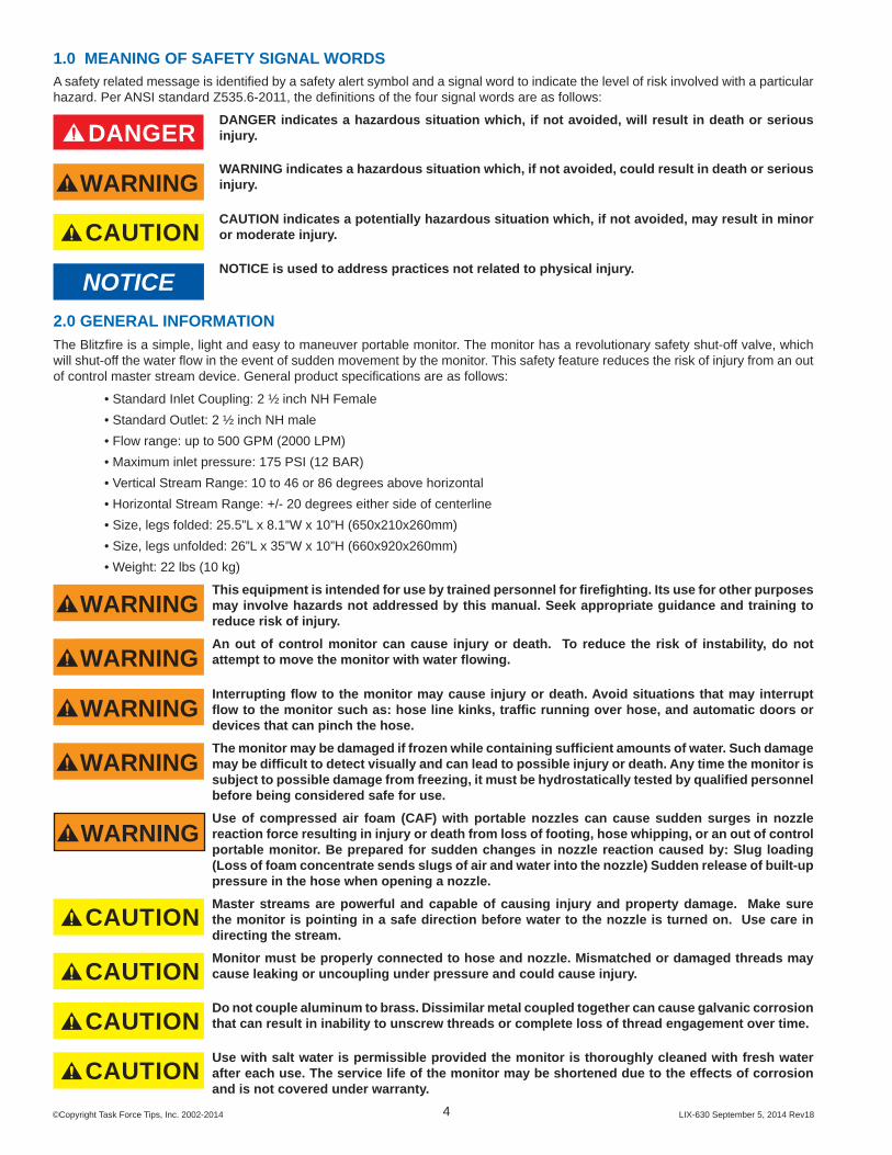
1.0 MEANING OF SAFETY SIGNAL WORDSA safety related message is identifi ed by a safety alert symbol and a signal word to indicate the level of risk involved with a particular hazard. Per ANSI standard Z535.6-2011, the defi nitions of the four signal words are as follows:
DANGERDANGER indicates a hazardous situation which, if not avoided, will result in death or serious injury.
WARNINGWARNING indicates a hazardous situation which, if not avoided, could result in death or serious injury.
CAUTIONCAUTION indicates a potentially hazardous situation which, if not avoided, may result in minor or moderate injury.
NOTICENOTICE is used to address practices not related to physical injury.

©Copyright Task Force Tips, Inc. 2002-2014 LIX-630 September 5, 2014 Rev185
2.1 BLITZFIRE PART IDENTIFICATIONThe Blitzfi re is available in standard and high elevation models Figure 2.1 identifi es the various parts and controls on a standard Blitzfi re portable monitor. Parts and controls for a high elevation model are similar.
Elevation HoldingMechanism
Valve Handle
Serial Number
Carbide Tipped Spike
Folding Leg
Handle Locking Knob
Tie Off Point
Pivoting Outlet
Pivoting Inlet
See Section 6for Blitzfire Oscillators
Figure 2.1 Blitzfi re Parts and Controls
2.2 FLOW CONTROL VALVE The Blitzfi re has a valve that can be used to control the fl ow and acts as a safety shut-off feature. The valve is shut-off when the valve handle is fully forward. The valve is fully on when the valve handle is fully back. The valve can be opened to any of six detented fl ow positions. These detented positions allow the monitor operator to regulate the fl ow depending on the need or what can be safely and effectively handled. Figure 2.2 illustrates the positions of the valve handle.
Detent Flow Positions
LOCKEDCLOSEDON
Pull Knob To Unlock Handle
Figure 2.2 Valve Handle Positions

©Copyright Task Force Tips, Inc. 2002-2014 LIX-630 September 5, 2014 Rev186
2.2.1 UNLOCKING THE VALVE HANDLE FROM THE CLOSED POSITIONThe valve handle is locked in the closed position so that the valve handle may be used to carry the Blitzfi re without the valve inadvertently opening. To unlock the valve handle from the closed position: 1. Pull knob on right side of the valve handle. 2. While pulling on knob, open the valve with the other hand.As soon as valve is opened the knob may be released. The valve handle may be moved to any detent valve position by pushing or pulling on the valve handle. When the valve is closed the valve handle automatically locks and must be unlocked again to reopen. The valve opening procedure is shown in fi gure 2.2.1.
Pull Knob
Open Valve
Figure 2.2.1 Valve Opening Procedure

©Copyright Task Force Tips, Inc. 2002-2014 LIX-630 September 5, 2014 Rev187
2.2.2 SAFETY SHUT-OFF VALVE OPERATIONThe Blitzfi re is equipped with a Safety Shut-Off Valve. The Safety Shut-Off Valve will shut off the monitor’s fl ow if the monitor starts to move. The Safety Shut-Off Valve relies on acceleration of the Blitzfi re as the signal to activate. It activates at approximately one G of sideways acceleration. Placing the Blitzfi re on tilted surfaces (greater than 10 degrees) may inhibit the resetting of the Safety Shut-Off Valve. The hose connected to the Blitzfi re should contain any forward or backwards motion to safe levels.NOTE: To make the Blitzfi re not shut off completely, see the card titled “Instructions to Maintain Minimal Water Flow When the Safety Shut-off Activates”. (LIX-640)Safety shut-off valve operation: 1. Set up monitor and charge the hose. 2. Point the nozzle in the desired direction. 3. Open the valve by pulling the locking pin and pulling back on the valve handle (see section 2.2.1) 4. Place the valve handle in the desired detent position (further back for more fl ow, further forward for less). 5. If the monitor starts to slide, the safety valve will sense the movement and release the valve. • An internal spring and water pressure will move the valve forward to the closed position and shut off the water fl ow. • The valve handle will lock in the closed position. 6. The safety shut-off valve will automatically reset. 7. After the cause of the sliding has been corrected, reopen the valve as outlined in step 3.IMPORTANT: Valve must be fully closed to reset the safety shut-off mechanism. Once tripped the valve handle will not stay open unless the mechanism is reset by fully closing the valve.If the safety shut-off valve fails to reset, the valve will not remain open. Failure to reset may be due to placing the monitor on an excessively sloped surface.
WARNINGThe safety shut-off valve is only sensitive to sideways acceleration of the monitor. Keep the hose directly behind the monitor to reduce potential acceleration in the forward and backward direction. Do not loop hose in front of monitor.
WARNINGThe safety shut-off valve needs approximately one G of sideways acceleration to activate. At low accelerations the monitor may travel several yards (meters) and gain enough velocity to cause injury before the safety shut-off valve activates. Personnel several feet away and in the potential path of a sliding monitor are at risk of injury. Keep non operating personnel out of the potential path of a sliding monitor.
WARNINGImproper repairs may result in a malfunctioning safety shut-off valve. If repair is needed on the safety shut-off valve, return the monitor to Task Force Tips.
2.2.3 SAFETY SHUT-OFF VALVE TEST
WARNINGTo avoid injury or death, test safety shut-off valve before each use.
With hose uncharged and Blitzfi re on a level surface: 1. Open the Valve Handle to the fully open position. 2. Grasp the monitor and give it a sideways jerk, rotate to trip the valve or hit on the side with a rubber mallet. 3. The Valve Handle should move to the closed position. Note: With water fl owing the valve has additional forces on it that will close the valve the rest of the way.If the Safety Shut-Off Valve fails the test, return the monitor to Task Force Tips to restore proper functioning of the safety shut-off valve. If the monitor is used before repair, the user accepts the risk of an out of control monitor.
WARNINGThe safety shut-off valve is intended to shut off the monitor when it moves. It will not prevent it from moving. The device shall limit the motion and injury that may occur once the monitor starts to move. Use adequate means to secure the monitor to prevent injury.
WARNINGInjury or death from an out of control monitor can occur. If monitor gets out of control retreat from monitor immediately. Do not attempt to regain control of monitor while it is fl owing.

©Copyright Task Force Tips, Inc. 2002-2014 LIX-630 September 5, 2014 Rev188
2.2.4 MANUAL OVERRIDE OF SAFETY SHUT-OFF VALVEOn sloping terrain it may be necessary to manually override the Safety Shut-Off Valve. The Safety Shut-Off Valve can be overridden by holding the valve handle in an open position.
WARNINGDo not tie or prop open the valve handle. Tampering with the valve handle will render the Safety Shut-Off inoperable and may result in injury or death.
2.2.5 SLOW CLOSE VALVE FEATUREThe Blitzfi re has a valve damping mechanism to slow valve closure as it approaches OFF to reduce the effects of water hammer. The damping mechanism has a vane moving in dampening fl uid connected to the valve handle on the left side of the monitor.
WARNINGDo not add or change dampening fl uid. Improper servicing may result in a malfunctioning safety shut-off valve. If service is needed on the slow close device, contact Task Force Tips service department at 800-348-2686.
WARNING“Water Hammer” is present any time a valve is closed when water is fl owing. The effects of water hammer can be made worse with short hose lines, small hose lines, and high fl ows. All personnel operating in the vicinity of charged hose lines should be especially cautious around any hose that is providing high fl ows that might be shut off quickly in an emergency. The dampening device in the Blitzfi re monitor reduces the effects of water hammer but DOES NOT ELIMINATE IT!
2.3 FOLDING LEGSThe Blilzfi re has two legs that fold for storage and unfold for operation. The legs are held in the folded and unfolded position by spring detents. To fold or unfold the legs: 1. Grasp the spike end of one leg and pivot it to the folded or unfolded position. 2. Repeat for the other leg.
2.3.1 CARBIDE SPIKESThe Blitzfi re monitor has 3 tungsten carbide tipped spikes on the legs and the base to resist sliding by digging into the surface the monitor is sitting on. The amount of sliding force these spikes can withstand depends upon the amount of downward and sideways force that is on the monitor and the hardness and texture of the surface the spikes are in contact with. At low elevation angles it is diffi cult for these spikes to resist sliding. These spikes are essential to safe operation of the monitor and must be in contact with the ground at all times. Set the monitor on an even surface so that all three spikes contact the ground. Replace any spike if the tip diameter exceeds 1/16 inch (1.6 mm). Order replacement spike kit: XX482-KIT.
WARNING For stable operation the three spikes must maintain in contact with the ground. Do not place the Blitzfi re on top of debris, objects, or uneven terrain that would keep any of the spikes from contacting the ground.
WARNING On hard slippery surfaces the spikes may provide little resistance to sliding. In these cases the monitor should be tied off or the legs hooked on stationary objects to keep the monitor in position. Also, a person’s weight applied to the monitor may help increase resistance to sliding.
CAUTION Spikes must be sharp to provide resistance to sliding. Replace any spike if the tip diameter exceeds 1/16 inch (1.6 mm).
CAUTION Spikes are sharp and exposed. Use care around spikes to avoid injury and damage to clothing or other property.
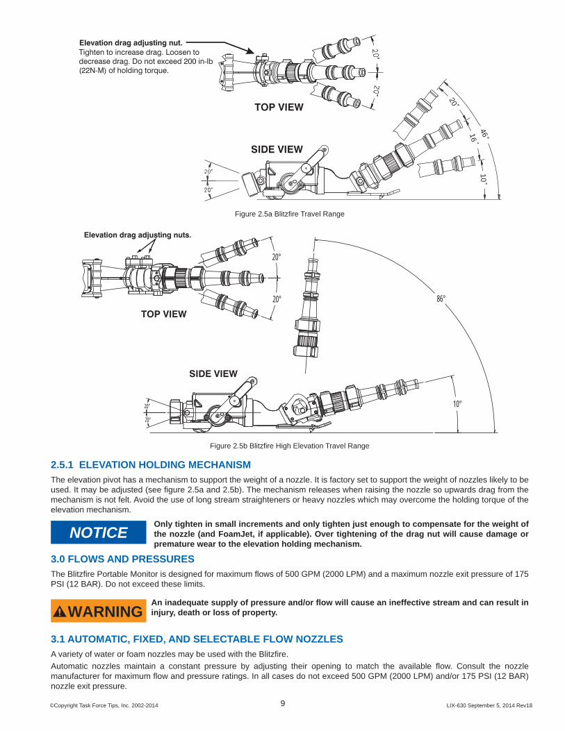
2.4 PIVOTING INLETThe Blitzfi re has a pivoting inlet so that different size hoses can be used without lifting the spikes off the ground. The pivoting inlet also allows the monitor to be positioned on porches, stair landings, and the like. The pivot moves up and down 20 degrees. The Blitzfi re is equipped with three spikes to provide traction when fl owing from the ground. For the spikes to provide traction they must remain in contact with the ground. Assure that the hose is not on top of anything that would cause the spikes to lift off the ground. Figure 2.5a and 2.5b shows the inlet pivot.
2.5 OUTLET PIVOTSFigure 2.5a and 2.5b shows the outlet pivot travel range. Push or pull on the nozzle to redirect the stream. The pivots are easy to reposition under pressure and are good for rapid redirecting of the stream. However, if the pivot is rapidly bumped against its travel limit, the Safety Shut-Off Valve may activate and shut off the monitor. Figures 2.5a and 2.5b shows the outlet pivots range of motion.The Blitzfi re has been designed to operate at very low elevation angles to maximize usefulness for interior attack. As with any monitor, when the elevation angle is low the risk of sliding is increased. This is because at low elevation angles the reaction force is more horizontal and less vertical.
©Copyright Task Force Tips, Inc. 2002-2014 LIX-630 September 5, 2014 Rev189
TOP VIEW
Elevation drag adjusting nut. Tighten to increase drag. Loosen todecrease drag. Do not exceed 200 in-lb(22N-M) of holding torque.
SIDE VIEW
46
20
1610
Figure 2.5a Blitzfi re Travel Range
20°
20° 86°
20°
20° 10°
TOP VIEW
SIDE VIEW
Elevation drag adjusting nuts.
Figure 2.5b Blitzfi re High Elevation Travel Range
2.5.1 ELEVATION HOLDING MECHANISMThe elevation pivot has a mechanism to support the weight of a nozzle. It is factory set to support the weight of nozzles likely to be used. It may be adjusted (see fi gure 2.5a and 2.5b). The mechanism releases when raising the nozzle so upwards drag from the mechanism is not felt. Avoid the use of long stream straighteners or heavy nozzles which may overcome the holding torque of the elevation mechanism.
NOTICEOnly tighten in small increments and only tighten just enough to compensate for the weight of the nozzle (and FoamJet, if applicable). Over tightening of the drag nut will cause damage or premature wear to the elevation holding mechanism.
3.0 FLOWS AND PRESSURESThe Blitzfi re Portable Monitor is designed for maximum fl ows of 500 GPM (2000 LPM) and a maximum nozzle exit pressure of 175 PSI (12 BAR). Do not exceed these limits.
WARNINGAn inadequate supply of pressure and/or fl ow will cause an ineffective stream and can result in injury, death or loss of property.
3.1 AUTOMATIC, FIXED, AND SELECTABLE FLOW NOZZLESA variety of water or foam nozzles may be used with the Blitzfi re.Automatic nozzles maintain a constant pressure by adjusting their opening to match the available fl ow. Consult the nozzle manufacturer for maximum fl ow and pressure ratings. In all cases do not exceed 500 GPM (2000 LPM) and/or 175 PSI (12 BAR) nozzle exit pressure.
©Copyright Task Force Tips, Inc. 2002-2014 LIX-630 September 5, 2014 Rev1810
3.2 STACKED TIPS OR SMOOTHBORE NOZZLES
NOZZLEDIAMETER
NOZZLE EXIT PRESSURE50 PSI 80 PSI 100 PSI 150 PSI 175 PSI
FLOW(GPM)
REACTION(LBS)
FLOW(GPM)
REACTION(LBS)
FLOW(GPM)
REACTION(LBS)
FLOW(GPM)
REACTION(LBS)
FLOW(GPM)
REACTION(LBS)
1.0 INCH 210 80 266 126 297 157 364 236 390 2751-1/4 INCH 328 120 415 196 464 245 — — — —1-1/2 INCH 473 177 — — — — — — — —
NOZZLEDIAMETER
NOZZLE EXIT PRESSURE4 BAR 6 BAR 8 BAR 10 BAR 12 BAR
FLOW(L/min)
REACTION(KG)
FLOW(L/min)
REACTION(KG)
FLOW(L/min)
REACTION(KG)
FLOW(L/min)
REACTION(KG)
FLOW(L/min)
REACTION(KG)
25 MM 830 40 1000 60 1200 80 1300 100 1400 12032 MM 1300 70 1700 100 1900 130 — — — —38 MM 1900 90 — — — — — — — —
FLOW EXCEEDS RATING OF BLITZFIRE PORTABLE MONITOR
3.3 STREAM STRAIGHTENERSStream quality, especially with smooth bore nozzles, is generally improved with the use of a stream straightener. A stream straightener is integrated into the exit of the monitor.3.4 USE WITH FOAMThe Blitzfi re may be used with various foam nozzles and foam solutions. Refer to fi re service training for the proper use of foam.3.5 USE WITH SALT WATERUse with salt water is permissible provided the monitor is thoroughly cleaned with fresh water after each use. The service life of the monitor may be shortened due to the effects of corrosion and is not covered under warranty.
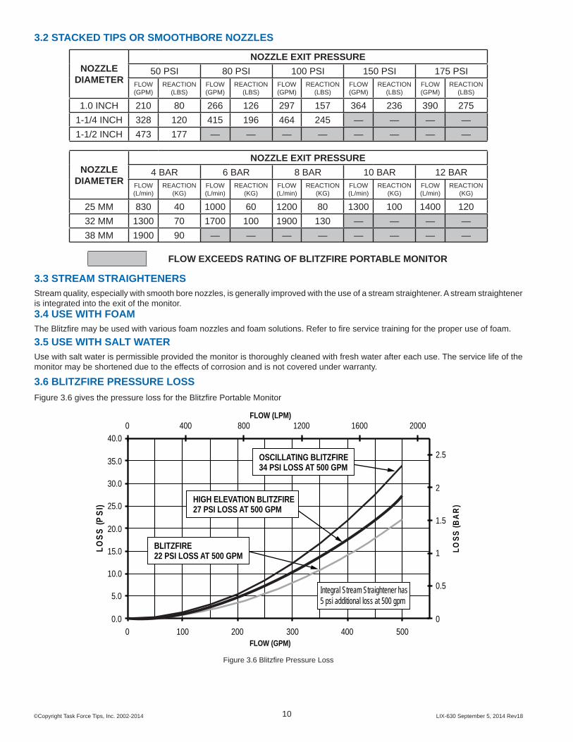
3.6 BLITZFIRE PRESSURE LOSSFigure 3.6 gives the pressure loss for the Blitzfi re Portable Monitor
0.0
5.0
10.0
15.0
20.0
25.0
30.0
35.0
40.0
0 100 200 300 400 500FLOW (GPM)
LOSS
(PSI
)
0
0.5
1
1.5
2
2.5
0 400 800 1200 1600 2000FLOW (LPM)
LOSS
(BA
R)
BLITZFIRE22 PSI LOSS AT 500 GPM
OSCILLATING BLITZFIRE34 PSI LOSS AT 500 GPM
HIGH ELEVATION BLITZFIRE27 PSI LOSS AT 500 GPM
Integral Stream Straightener has5 psi additional loss at 500 gpm
Figure 3.6 Blitzfi re Pressure Loss

©Copyright Task Force Tips, Inc. 2002-2014 LIX-630 September 5, 2014 Rev1811
4.0 DEPLOYMENT OF BLITZFIREIt is the responsibility of the individual fi re department or agency to determine physical capabilities and suitability for an individual’s use of this equipment.
4.1 CARRYING WITH AN UNCHARGED HOSEOn a preconnected hoseline the Blitzfi re may be carried over the shoulder with the legs folded as illustrated in fi gure 4.1.
Figure 4.1 Carrying the Blitzfi re on an Uncharged Hose
4.2 ADVANCING WITH A CHARGED HOSEOn a charged hose the Blitzfi re may be advanced by holding the valve handle and one of the legs as shown in fi gure 4.2. Valve handle should be locked in the closed position to keep the valve from inadvertently opening.
Figure 4.2 Advancing the Blitzfi re with a Charged Hose
5.0 ANCHORINGThe nozzle reaction force on the Blitzfi re may be as high as 330 lbs - 500 GPM at 175 PSI (150 kg- 2000 LPM at 12 BAR). This nozzle reaction must be restrained to keep the monitor from moving.The monitor should be anchored from moving by one or more of these methods:
METHOD RISK of MOVINGAnchoring by Weight High
Anchoring by Spike Holds MediumHooking legs on vertical surfaces Medium
Using a tie off strap Low

©Copyright Task Force Tips, Inc. 2002-2014 LIX-630 September 5, 2014 Rev1812
5.1 ANCHORING BY WEIGHTOn surfaces with good traction a person’s weight on the monitor and/or hose may be suffi cient to keep the monitor from moving. This is highly dependant on the friction of the surface. The ability to keep one or more than one person’s weight on the monitor is subject to operator fatigue and may not be as reliable as other methods. Operating at limited fl ows will reduce the risk.
5.2 ANCHORING BY SPIKE HOLDSAnchoring by spike holds is defi ned as intentionally placing one or more spikes into a crack, hole, or other hold to anchor the monitor from moving. On hard smooth surfaces such as ceramic tile, smooth concrete, marble, terrazzo, or steel decking the Blitzfi re’s spikes may not hold well. Placing the spikes into cracks, expansion joints, or gratings or the like will help hold the monitor from sliding. Even with the spikes anchored, sliding may be caused by the surface cracking under the load, or from the hose or nozzle moving the monitor thereby dislodging the spikes from their hold. Figure 4.3.1 shows a close up of a spike caught in a crack.The holding ability of the spikes on soft surfaces such as sand, gravel and mud is generally poor, therefore other anchoring methods should be considered.
Figure 4.3.1 Spike Caught in a Crack
5.3 ANCHORING BY HOOKING LEGSThe legs on the Blitzfi re point back slightly so they can act as a hook for anchoring on posts, walls, door frames or other fi xed objects. Sliding can occur if the legs are unhooked due to the infl uence of the hose, nozzle, or operator. See fi gure 4.3.2 for illustrations of hooking the legs.
Good Nozzle reaction keeps leg hooked.
Object is close to hose.
PoorNozzle reaction tends to unhook leg

©Copyright Task Force Tips, Inc. 2002-2014 LIX-630 September 5, 2014 Rev1813
GoodNozzle reaction keeps leg hooked.
Hose hits wall and helps hold position.
PoorNozzle reaction tends to unhook leg.
Figure 5.3 Hooking Legs to Gain Support
5.4 ANCHORING BY TYING OFFThe safest method of restraining the monitor is to use a tie down strap. It is inherently more reliable than other methods since it does not rely on traction or digging in of the spikes. It is also the safest method because, even if the monitor moves, its travel is limited by the strap. A forward attachment point and a strap are provided with the Blitzfi re. A loop on the end of the strap may be placed over the anchor point or the strap may be wrapped around an object, such as a tree, and the snap end of the strap passed through the loop and pulled tight. Keep the entire length of the strap as close to the ground as possible. Snap the hook into the hole in the front of the Blitzfi re. If the strap is too short to reach a suitable anchor, it may be extended with strong rope or chain. Keep the distance between the Blitzfi re and anchor as short as possible. Remove all slack between the Blitzfi re and anchor before fl owing water. Figure 4.3.3 shows the elements of tying off the monitor.
Figure 4.3.3 Tying Off of Blitzfi re Monitor

©Copyright Task Force Tips, Inc. 2002-2014 LIX-630 September 5, 2014 Rev1814
6.0 OSC OSCILLATING UNITAn automatic oscillating mechanism is available for the Blitzfi re Monitor. The Blitzfi re Monitor can be purchased with the oscillating mechanism factory installed or added at the factory later.
6.1 SAFETY - OSCILLATOR
DANGERDo not attempt to modify this oscillating mechanism to fi t any other monitor. To do so will cause the reaction force of the nozzle to be unaligned with the center of rotation. The monitor may spin very fast with a very high force.
WARNINGKeep hands and fi ngers away from the moving parts of the oscillating unit when water is fl owing. There are moving parts that can pinch fi ngers and hands.
WARNINGMake sure the Blitzfi re is on a fi rm surface with adequate holding power. As the nozzle goes back and forth, the reaction force is acting in different directions on the leg spikes. Surfaces such as asphalt, turf and dirt generally have good holding power. Surfaces like concrete and loose gravel hold poorly.
CAUTIONBecause the nozzle attached to the Blitzfi re must slow down, stop and reverse direction at the end of each sweep, the ends of the covered area will receive more water than the center. If the center area of coverage needs the most cooling, occasionally narrow the area of coverage or use the oscillator manually.
CAUTIONBecause the oscillating mechanism is always moving, the monitor should be manned at all times. When oscillation is disengaged, be prepared for unintended movement of the nozzle.
6.2 GENERAL - OSCILLATORThe Blitzfi re oscillating mechanism can be used for exposure protection, cooling, or any other situation where it is desirable to have a monitor sweep back and forth.
The oscillating mechanism is driven by a turbine wheel. A worm gear drive reduces the speed and increases the torque of the turbine wheel. A simple crank mechanism makes the outlet of the Blitzfi re and the nozzle attached to it move back and forth. The horizontal sweep can be set for a 20, 30 and 40 degree sweep. The oscillating mechanism can be uncoupled and the water stream can be aimed manually. The speed of oscillation is a function of fl ow rate, see the Blitzfi re Oscillation Speed graph on page 15. A minimum fl ow rate of 175 GPM is required for proper oscillator operation.
6.3 OSCILLATOROperating details for the Blitzfi re Oscillator are shown in fi gure 6.3.The Blitzfi re’s oscillator is protected by a shock absorber system. If the nozzle encounters an obstruction the shock absorber will compress or extend as needed to protect the gears from overload.
LIFT TO CHANGE SWEEP SETTING 1
PULL KNOB & TURNTO STOP OSCILLATION
SLIDE TOCHANGEANGLE
2
SWEEP
30°
20°
40°
Fig. 6.3 Blitzfi re Monitor Oscillator

©Copyright Task Force Tips, Inc. 2002-2014 LIX-630 September 5, 2014 Rev1815
6.4 OSCILLATION SPEED AND COVERAGEOscillation speed: The chart shows how many times per minute the oscillator makes one complete cycle as a function of fl ow. The higher the fl ow, the faster it oscillates.For nozzle reach, refer to the operation manual for the specifi c nozzle. For reach with oscillation, subtract 20% from the distance.
APPROXIMATE CYCLES/MIN
GPM L/MIN
8 175 65013 250 100021 375 150028 500 2000
BLITZFIRE OSCILLATION SPEED
200
175
150
125
100
75
50
0
DIS
TAN
CE
IN F
EET
20 DEGREES
30 DEGREES
40 DEGREES
WIDTH OF COVERAGE150 / 45m
125 / 38m
100 / 30m
75 / 23m
50 / 15m
COVERAGE AREAOF BLITZFIRE OSCILLATING UNIT
61m
53m
45m
38m
30m
22m
15m
DIS
TAN
CE
IN M
ETER
S
Fig. 6.4 Oscillation Speed and Coverage
NOTICEThe type of nozzle and fl ow pressure are critical to the coverage area. The graph shows coverage area based on the movement capability of the oscillating mechanism. Actual coverage will depend on fl ow, pressure, type of nozzle, angle of fog pattern and wind conditions.

©Copyright Task Force Tips, Inc. 2002-2014 LIX-630 September 5, 2014 Rev1816
7.0 STORAGEThe monitor may be stored pre-connected to its hose on the optional storage bracket, TFT part number XX-B. The storage bracket may be mounted on a horizontal surface, or a vertical surface with the nozzle end pointing up or sideways. Mounting instructions are included with the bracket.
CAUTIONThe storage bracket is not intended to support the nozzle reaction forces from a fl owing monitor.
8.0 MAINTENANCEThe Blitzfi re monitor requires little maintenance. The unit should be kept clean and free of dirt by rinsing with water after each use. Any inoperable or damaged part should be repaired or replaced.
CAUTIONAny alterations to the Blitzfi re and its markings could diminish safety and constitutes a misuse of this product.
MAINTENANCE CHECK LIST: • Safety shut-off valve is operational (see section 2.2.3) • Valve label legible • Legs pivot freely and detents hold folded or unfolded position • Spikes are sharp. Replace if tip diameter exceeds 1/16 inch (1.6 mm). • Inlet coupling rotates freely • Inlet pivots freely up and down • Pull pin for Valve Handle locking locks and releases easily • Valve Handle moves smoothly without binding • Valve Handle stays in detent positions • Outlet pivots freely from side to side • Outlet pivots freely upward • Outlet pivot has suffi cient drag to support weight of nozzle • Tie down strap is in good condition; no frays on strap or damage to hook
9.0 WARRANTYTask Force Tips, Inc., 3701 Innovation Way, Valparaiso, Indiana 46383-9327 USA (“TFT”) warrants to the original purchaser of its Blitzfi re Monitor (“equipment”), and to anyone to whom it is transferred, that the equipment shall be free from defects in material and workmanship during the fi ve (5) year period from the date of purchase.TFT’s obligation under this warranty is specifi cally limited to replacing or repairing the equipment (or its parts) which are shown by TFT’s examination to be in a defective condition attributable to TFT. To qualify for this limited warranty, the claimant must return the equipment to TFT, at 3701 Innovation Way, Valparaiso, Indiana 46383-9327 USA, within a reasonable time after discovery of the defect. TFT will examine the equipment. If TFT determines that there is a defect attributable to it, it will correct the problem within a reasonable time. If the equipment is covered by this limited warranty, TFT will assume the expenses of repair.If any defect attributable to TFT under this limited warranty cannot be reasonably cured by repair or replacement, TFT may elect to refund the purchase price of the equipment, less reasonable depreciation, in complete discharge of its obligations under this limited warranty. If TFT makes this election, claimant shall return the equipment to TFT free and clear of any liens and encumbrances.This is a limited warranty. The original purchaser of the equipment, any person to whom it is transferred, and any person who is an intended or unintended benefi ciary of the equipment, shall not be entitled to recover from TFT any consequential or incidental damages for injury to person and/or property resulting from any defective equipment manufactured or assembled by TFT. It is agreed and understood that the price stated for the equipment is in part consideration for limiting TFT’s liability. Some states do not allow the exclusion or limitation of incidental or consequential damages, so the above may not apply to you.TFT shall have no obligation under this limited warranty if the equipment is, or has been, misused or neglected (including failure to provide reasonable maintenance) or if there have been accidents to the equipment or if it has been repaired or altered by someone else.THIS IS A LIMITED EXPRESS WARRANTY ONLY. TFT EXPRESSLY DISCLAIMS WITH RESPECT TO THE EQUIPMENT ALL IMPLIED WARRANTIES OF MERCHANTABILITY AND ALL IMPLIED WARRANTIES OF FITNESS FOR A PARTICULAR PURPOSE. THERE IS NO WARRANTY OF ANY NATURE MADE BY TFT BEYOND THAT STATED IN THE DOCUMENT.This limited warranty gives you specifi c legal rights, and you may also have other rights which vary from state to state.
Visit TFT’s web site at www.tft.com

©Copyright Task Force Tips, Inc. 2002-2014 LIX-630 September 5, 2014 Rev1817
10.0 EXPLODED VIEWS AND PARTS LISTS
10.1 SAFETY MECHANISM ASSEMBLY VIEW
VB500TO1/2" BALL
XX555PINVW360X193-10
TEFLON WASHER (2)
XX535PIVOT PIN
(3) PLACES
XX550RELEASE XX540
LEAF SPRINGXX510
VT37-16SNTTEETH + NUT
XX560EXTENSION
SPRING
XX570TRIP ROD
XX545RESET SPRING
VT10-24SH500(3) PLACES
XX530PAWL
NOT SHOWN: XX520 RETAINER PLATEVP188X.38HDP SPIRAL PIN

©Copyright Task Force Tips, Inc. 2002-2014 LIX-630 September 5, 2014 Rev1818
10.2 BLITZFIRE MONITOR EXPLODED VIEW
4
231
65
78
10
9
1112
13
1514
1617
FOR REPAIR INFORMATION ON THEAUTOMATIC SHUTOFF OR THE SLOWCLOSE MECHANISM, CONTACTTASK FORCE TIPS AT 800-348-2686.
2221
4142
36
1920
35
34
1615
1427
2625
24
23
B
A
C
651
50
23
4948
4746
4543
4443
40
39
3738
16
3031
32
2829
33
1819
20
5453
52

©Copyright Task Force Tips, Inc. 2002-2014 LIX-630 September 5, 2014 Rev1819
INDEX DESCRIPTION QTY ITEM #1 GASKET 2.5" 1 V31902 1/4-28 X 1/2 SOCKET SET SCREW 1 VT25-28SS5003 3/16" SS BALL 48 V21204 COUPLING 2.5" 1 M307*5 INLET SWIVEL 1 XX6056 O-RING-235 1 VO-235
7COVER PLATE 1 XX205COVER PLATE GASKET 1 XX200
8 10-24 1/2 BUTTON HEAD SCREW 4 VT10-24BH5009 INSTRUCTION LABEL 1 XL67010 10-24 X 1/4 SOCKET SET SCREW 1 VT10-24SS25011 QUAD-RING-231 1 VOQ-423112 DRAG DISK 1 XX64513 O-RING-109 2 VO-10914 DISC RETAINER 4 XX64215 WASHER 4 VW687X281-5016 1/4-28 X 1/2 BUTTON HEAD SCREW 6 VT25-28BH50017 1/4-20 X 1 BUTTON HEAD SCREW 2 VT25-20BH1.018 LEFT HANDLE 1 XX62119 3/8-16 X 1-1/2 BUTTON HEAD SCREW 2 VT37-16BH1.520 HANDLE LABEL 2 XL62021 LEFT LEG 1 XX470L
22BODY 1 XX600TRIP MECHANISM 1 XX910
23 SWIVEL TRUNNION 2 XX32024 SQUARE BUSHING 1 XX63025 CAM PIN 1 XX61026 O-RING-230 TEFLON 1 VO-230T27 DISK 1 XX64028 3/8-16 X 1.7 BUTTON HEAD SCREW 1 VT37-16BH1.729 PULL PIN 1 XX343
INDEX DESCRIPTION QTY ITEM #30 PULL PIN SPRING 1 XX34231 PULL PIN HOUSING 1 XX35532 PULL KNOB 1 XX34133 1/8 X 3/4 HDP SPIROL PIN 1 VP125X750H34 HANDLE TOP 1 XX62535 RIGHT HANDLE 1 XX62036 DETENT SPRING 4 XX65537 3/8" TORLON BALL 4 VB375TO38 LEG RETAINER 2 XX47539 LEG RETAINER PIN 2 XX47640 1/4-20 X 1 SOCKET HEAD SCREW 4 VT25-20SH1.041 RIGHT LEG 1 XX470R42 REAR SPIKE 2 X48243 O-RING-227 2 VO-22744 SLIDER 1 XX66045 VALVE PLUG 1 XX59046 3/8-24 X 1-3/4 SOCKET HEAD SCREW 1 VT37-24SH17547 PLUG SUPPORT 1 XX59448 LOCKING SLEEVE 1 XX57149 O-RING-241 1 VO-24150 WAVE SPRING WASHER 2 VW740X550-1651 5/16-18 X 1/4 SOCKET SET SCREW 2 VT31-18SS25052 EXIT 2.5" 1 XX310*53 O-RING-147 1 VO-14654 STREAM STRAIGHTENER INSERT 1 V4040
A BLITZFIRE OUTLET 1 SEE SECTION 10.3
B HIGH ELEVATION BLITZFIRE OUTLET 1 SEE SECTION 10.4
C HIGH ELEVATION BLITZFIRE OSCILLATOR 1 SEE SECTION 10.5
* - CONSULT FACTORY FOR SPECIAL THREADS
10.2 BLITZFIRE MONITOR EXPLODED VIEW PARTS LIST

©Copyright Task Force Tips, Inc. 2002-2014 LIX-630 September 5, 2014 Rev1820
10.3 STANDARD BLITZFIRE OUTLET EXPLODED VIEW
3
45
6
1
8
2
7
BLITZFIREBODY
OSCILLATOROR THREADED
EXIT
10.3 BLITZFIRE OUTLET [A] PARTS LIST
INDEX DESCRIPTION QTY ITEM #1 OUTLET 1 XX4202 1/8 NPT PLUG 1 VFSP1M SS3 SWIVEL TRUNNION 3 XX3204 FRONT LEG 1 XX4605 3/8-16 X 1/2 FLAT HEAD SOCKET SCREW 2 VT37-16FH7506 SPIKE 1 X4807 O-RING-235 1 VO-2358 RATCHET CLUTCH 1 XX830-KIT

©Copyright Task Force Tips, Inc. 2002-2014 LIX-630 September 5, 2014 Rev1821
INDEX DESCRIPTION QTY ITEM #1 OUTLET 1 XX4202 1/8 NPT PLUG 1 VFSP1M SS3 SWIVEL TRUNNION 4 XX3204 CAM 1 XX3225 1/4-20 X 1 SOCKET HEAD SCREW 4 VT25-20SH1.06 FRONT LEG 1 XX4607 3/8-16 X 1/2 FLAT HEAD SOCKET SCREW 2 VT37-16FH7508 SPIKE 1 X4809 O-RING-235 3 VO-23510 1ST SEGMENT 1 XX30611 RATCHET CLUTCH 2 XX830-KIT
10.4 HIGH ELEVATION BLITZFIRE OUTLET EXPLODED VIEW
39
9
11
10
11
1
2
76
54
3
8
BLITZFIREBODY
OSCILLATOROR THREADED
EXIT
10.4 HIGH ELEVATION BLITZFIRE OUTLET [B] PARTS LIST
©Copyright Task Force Tips, Inc. 2002-2014 LIX-630 September 5, 2014 Rev1822
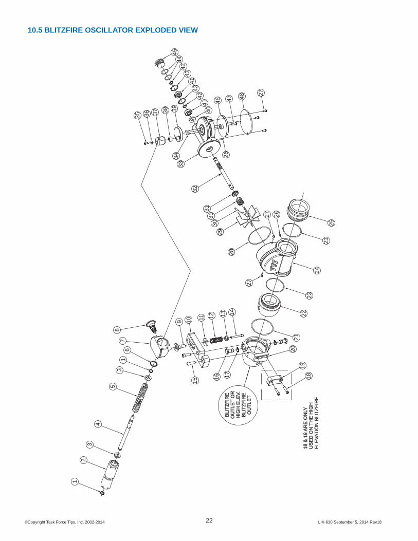
10.5 BLITZFIRE OSCILLATOR EXPLODED VIEW
1918
BLI
TZFI
RE
OU
TLE
T O
RH
IGH
ELE
V.B
LITZ
FIR
EO
UTL
ET
4041
4243
4143
4244
4533
34
32
3130
3129
28
2523
2423
2221
20
14131211109
1716
15
2627
27
18 &
19
AR
E O
NLY
US
ED
ON
TH
E H
IGH
ELE
VATI
ON
BLI
TZFI
RE
35
43
21
78
61
2748474626
38 39
35 36 37

©Copyright Task Force Tips, Inc. 2002-2014 LIX-630 September 5, 2014 Rev1823
INDEX DESCRIPTION QTY ITEM #1 SMALLEY RING 2 V42802 SPRING TUBE 1 XX3673 WASHER 2 XX3644 LINK 1 XX3635 SPRING 1 XX3716 SMALLEY RING 1 VR43407 SLIDER BLOCK 1 XX3688 LATCHING PULL PIN SUBASSEMBLY 1 XX9359 DETENT BUSHING 1 XX37610 ARM 1 XX06111 WASHER 1 XX37712 SPRING 1 C03113 SPRING RETAINER 1 XX37814 1/4-20 X 1.75 SOCKET HEAD SCREW 1 VT25-20SH1.715 5/16-18 X 1 SOCKET HEAD SCREW 2 VT31-18SH1.016 SWIVEL TRUNNION 2 XX32017 WAVE SPRING WASHER 2 VW740X550-1618 1/4-20 X 1 SOCKET HEAD SCREW 2 VT25-20SH1.019 CAM FOLLOWER 1 XX323
202ND SEGMENT 1 XX307EXIT SEGMENT XX305
21 O-RING-235 1 VO-23522 INLET BALL 1 XX01523 O-RING-147 2 VO-14724 WATERWAY 1 XX01025 EXIT OSC 2.5" 1 XX020*26 10-32 X 1/4 SOCKET SET SCREW 3 VT10-32SS25027 10-32 X 1/2 BUTTON HEAD SCREW 5 VT10E32BH50028 O-RING-153 1 VO-15329 TURBINE VANES 1 XX02530 5/32 X 7/8 HDP SPIROL PIN 1 V190031 TURBINE SEAL 1 XX03232 WORM AND SHAFT 1 XX03033 GEAR BOX 1 XX00534 1/8 X 3/4 HDP SPIROL PIN 2 VP125X750H35 BUTTON HEAD CAP SCREW 1 VT10-32BH50036 WASHER 1 VW500X203-6037 OFFSET ROD END 1 XX05738 SPHERICAL BUSHING 1 XX05839 CRANK 1 XX36240 CUP SEAL 1 XX03341 WORM SHAFT BEARING 2 XX03542 SNAP RING 1/2" EXTERNAL 2 VR425043 SNAP RING 1-1/8 INTERNAL 2 VR425544 O-RING-119 2 VO-11945 SHAFT CAP 1 XX03746 WORM GEAR 1 XX04047 1/4-20 X 7/8 SOCKET HEAD SCREW 1 VT25-20SH87548 COVER 1 XX045
* - CONSULT FACTORY FOR SPECIAL THREADS
10.5 OSCILLATOR [C] PARTS LIST

©Copyright Task Force Tips, Inc. 2002-2014 LIX-630 September 5, 2014 Rev18
TASK FORCE TIPS, INC.MADE IN USA • www.tft.com
3701 Innovation Way, Valparaiso, IN 46383-9327 USA800-348-2686 • 219-462-6161 • Fax 219-464-7155
11.0 OPERATION CHECKLISTMonitor must be inspected for proper operation and function according to this checklist before each use. Before fl owing water check:
1) There is no obvious damage such as missing, broken or loose parts.2) Hose and nozzle are securely attached.
7) Monitor is anchored: • Tied off• Hooked leg• Spike hold• Weight
3) Both legs are fully open.4) All three spikes are in contact with the ground.
8) Outlet pivots smoothly in all directions.
5) Valve handle locks when closed and releases.
Locks andunlocks
9) Safety Shut-Off valve is operational. (see section 2.2.3)
6) Inlet pivots freely. 10) Monitor is pointed in a safe direction.
WARNINGAny Blitzfi re monitor failing any part of the inspection checklist is unsafe and must have the problem corrected before use. Operating a Blitzfi re that fails any of the above inspections is a misuse of this equipment.