Instructions for Robust Fiber
52
Instructions for Robust Fiber Appendix 3 Robust routing methods Ver 1.3.2
Transcript of Instructions for Robust Fiber

ROBUST FIBER – Appendix 3, ROBUST ROUTING METHODS
1
Instructions for Robust Fiber Appendix 3 Robust routing methods Ver 1.3.2

ROBUST FIBER – Appendix 3, ROBUST ROUTING METHODS
2
ROBUST FIBER – Appendix 3, ROBUST ROUTING METHODS
3
CONTENTS
1. Introduction ............................................................................................................. 8
2. General ..................................................................................................................... 8
2.1 General advantages and disadvantages .................................................................. 9
2.2 Effective routing .................................................................................................... 10
3. General information for a fibre project .................................................................. 11
3.1 Staking / cable indication query ............................................................................ 11
3.2 Prior survey on site ................................................................................................ 11
3.3 Collocation ............................................................................................................. 11
3.4 Permits and land issues ......................................................................................... 11
3.5 TA plan ................................................................................................................... 13
3.6 Work environment ................................................................................................ 13
3.7 Environment .......................................................................................................... 14
3.8 Subsequent survey on site .................................................................................... 15
3.9 Warranties ............................................................................................................. 15
3.10 Consultation with County Administrative Board .................................................. 15
3.11 Drainage in farmland ............................................................................................. 16
3.12 Trees, roots and vegetation ................................................................................... 16
4 Excavation-free methods ........................................................................................ 17
4.1 Microtrenching ...................................................................................................... 17
4.1.1 Method .............................................................................................................................. 17
4.1.2 Machinery .......................................................................................................................... 17
4.1.3 Tools ................................................................................................................................... 17
4.1.4 Suitable environment ........................................................................................................ 18
4.1.5 Advantages ........................................................................................................................ 18
4.1.6 Restrictions (Disadvantages) ............................................................................................. 18
4.1.7 Excavation ......................................................................................................................... 18
4.1.8 Excavated material ............................................................................................................ 19
4.1.9 Duct bedding ...................................................................................................................... 19
4.1.10 Backfilling ......................................................................................................................... 19
4.1.11 Refilling ............................................................................................................................ 19
4.1.12 Restoration ...................................................................................................................... 19
4.1.13 Environmental impact ..................................................................................................... 19
4.1.14 Duct type .......................................................................................................................... 19
4.1.15 Duct routing ..................................................................................................................... 19
4.2 End milling ............................................................................................................. 20
4.2.1 Method .............................................................................................................................. 20
4.2.2 Machinery .......................................................................................................................... 20
4.2.3 Tools ................................................................................................................................... 21
4.2.4 Suitable environment ........................................................................................................ 21
4.2.5 Advantages ........................................................................................................................ 21

ROBUST FIBER – Appendix 3, ROBUST ROUTING METHODS
4
4.2.6 Restrictions (Disadvantages) ............................................................................................. 22
4.2.7 Excavation .......................................................................................................................... 22
4.2.8 Excavated material ............................................................................................................ 22
4.2.9 Duct bedding ...................................................................................................................... 22
4.2.10 Backfilling ......................................................................................................................... 22
4.2.11 Refilling ............................................................................................................................ 23
4.2.12 Restoration ...................................................................................................................... 23
4.2.13 Environmental impact ..................................................................................................... 23
4.2.14 Duct type .......................................................................................................................... 24
4.2.15 Duct routing ..................................................................................................................... 24
4.3 Ploughing ............................................................................................................... 25
4.3.1 Method .............................................................................................................................. 25
4.3.2 Machinery .......................................................................................................................... 25
4.3.3 Tools ................................................................................................................................... 25
4.3.4 Suitable environment ........................................................................................................ 26
4.3.5 Advantages ........................................................................................................................ 26
4.3.6 Restrictions (Disadvantages) ............................................................................................. 26
4.3.7 Excavation .......................................................................................................................... 26
4.3.8 Excavated material ............................................................................................................ 26
4.3.9 Duct bedding ...................................................................................................................... 27
4.3.10 Backfilling ......................................................................................................................... 27
4.3.11 Refilling ............................................................................................................................ 27
4.3.12 Restoration ...................................................................................................................... 27
4.3.13 Environmental impact ..................................................................................................... 27
4.3.14 Duct type .......................................................................................................................... 27
4.3.15 Duct routing ..................................................................................................................... 27
4.4 Chain excavation .................................................................................................... 28
4.4.1 Method .............................................................................................................................. 28
4.4.2 Machinery .......................................................................................................................... 28
4.4.3 Tools ................................................................................................................................... 28
4.4.4 Suitable environment ........................................................................................................ 29
4.4.5 Advantages ........................................................................................................................ 29
4.4.6 Restrictions (Disadvantages) ............................................................................................. 29
4.4.7 Excavation .......................................................................................................................... 29
4.4.8 Excavated material ............................................................................................................ 29
4.4.9 Duct bedding ...................................................................................................................... 29
4.4.10 Backfilling ......................................................................................................................... 29
4.4.11 Refilling ............................................................................................................................ 29
4.4.12 Restoration ...................................................................................................................... 29
4.4.13 Environmental impact ..................................................................................................... 29
4.4.14 Duct type .......................................................................................................................... 30
4.4.15 Duct routing ..................................................................................................................... 30
4.5 Suction excavation ................................................................................................. 31
4.5.1 Method .............................................................................................................................. 31
4.5.2 Machinery .......................................................................................................................... 31

ROBUST FIBER – Appendix 3, ROBUST ROUTING METHODS
5
4.5.3 Tools ................................................................................................................................... 31
4.5.4 Suitable environment ........................................................................................................ 32
4.5.5 Advantages ........................................................................................................................ 32
4.5.6 Restrictions (Disadvantages) ............................................................................................. 32
4.5.7 Excavation .......................................................................................................................... 32
4.5.8 Excavated material ............................................................................................................ 32
4.5.9 Duct bedding ...................................................................................................................... 32
4.5.10 Backfilling ......................................................................................................................... 32
4.5.11 Refilling ............................................................................................................................ 32
4.5.12 Restoration ...................................................................................................................... 32
4.5.13 Environmental impact ..................................................................................................... 33
4.5.14 Duct type .......................................................................................................................... 33
4.5.15 Duct routing ..................................................................................................................... 33
4.6 Pressing .................................................................................................................. 34
4.6.1 Method .............................................................................................................................. 34
4.6.2 Machinery .......................................................................................................................... 34
4.6.3 Tools ................................................................................................................................... 34
4.6.4 Suitable environment ........................................................................................................ 34
4.6.5 Advantages ........................................................................................................................ 35
4.6.6 Restrictions (Disadvantages) ............................................................................................. 35
4.6.7 Excavation .......................................................................................................................... 35
4.6.8 Excavated material ............................................................................................................ 35
4.6.9 Duct bedding ...................................................................................................................... 35
4.6.10 Backfilling ......................................................................................................................... 35
4.6.11 Refilling ............................................................................................................................ 35
4.6.12 Restoration ...................................................................................................................... 35
4.6.13 Environmental impact ..................................................................................................... 35
4.6.14 Duct type .......................................................................................................................... 36
4.6.15 Duct routing ..................................................................................................................... 36
4.7 Impact mole........................................................................................................... 37
4.7.1 Method .............................................................................................................................. 37
4.7.2 Machinery .......................................................................................................................... 37
4.7.3 Tools ................................................................................................................................... 37
4.7.4 Suitable environment ........................................................................................................ 38
4.7.5 Advantages ........................................................................................................................ 38
4.7.6 Restrictions (Disadvantages) ............................................................................................. 38
4.7.7 Excavation .......................................................................................................................... 38
4.7.8 Excavated material ............................................................................................................ 38
4.7.9 Duct bedding ...................................................................................................................... 38
4.7.10 Backfilling ......................................................................................................................... 38
4.7.11 Refilling ............................................................................................................................ 38
4.7.12 Restoration ...................................................................................................................... 39
4.7.13 Environmental impact ..................................................................................................... 39
4.7.14 Duct type .......................................................................................................................... 39
4.7.15 Duct routing ..................................................................................................................... 39
ROBUST FIBER – Appendix 3, ROBUST ROUTING METHODS
6
4.8 Directional drilling ................................................................................................. 40
8.1 Method ................................................................................................................................. 40
4.8.2 Machinery .......................................................................................................................... 41
4.8.3 Tools ................................................................................................................................... 41
4.8.4 Suitable environment ........................................................................................................ 42
4.8.5 Advantages ........................................................................................................................ 42
4.8.6 Restrictions (Disadvantages) ............................................................................................. 43
4.8.7 Excavation .......................................................................................................................... 43
4.8.8 Excavated material ............................................................................................................ 43
4.8.9 Duct bedding ...................................................................................................................... 43
4.8.10 Backfilling ......................................................................................................................... 43
4.8.11 Refilling ............................................................................................................................ 43
4.8.12 Restoration ...................................................................................................................... 43
4.8.13 Environmental impact ..................................................................................................... 43
4.8.14 Duct type .......................................................................................................................... 44
4.8.15 Duct routing ..................................................................................................................... 44
4.9 Hammer drilling ..................................................................................................... 45
4.9.1 Method .............................................................................................................................. 45
4.9.2 Machinery .......................................................................................................................... 45
4.9.3 Tools ................................................................................................................................... 45
4.9.4 Suitable environment ........................................................................................................ 46
4.9.5 Advantages ........................................................................................................................ 46
4.9.6 Restrictions (Disadvantages) ............................................................................................. 46
4.9.7 Excavation .......................................................................................................................... 46
4.9.8 Excavated material ............................................................................................................ 46
4.9.9 Duct bedding ...................................................................................................................... 46
4.9.10 Backfilling ......................................................................................................................... 46
4.9.11 Refilling ............................................................................................................................ 46
4.9.12 Restoration ...................................................................................................................... 47
4.9.13 Environmental impact ..................................................................................................... 47
4.9.14 Duct type .......................................................................................................................... 47
4.9.15 Duct routing ..................................................................................................................... 47
5 Excavation methods ............................................................................................... 48
5.1 Excavation with excavator (Traditional excavator) ................................................ 48
5.1.1 Method .............................................................................................................................. 48
5.1.2 Machinery .......................................................................................................................... 48
5.1.3 Tools ................................................................................................................................... 48
5.1.4 Suitable environment ........................................................................................................ 48
5.1.5 Advantages ........................................................................................................................ 49
5.1.6 Restrictions (Disadvantages) ............................................................................................. 49
5.1.7 Excavation .......................................................................................................................... 49
5.1.8 Excavated material ............................................................................................................ 49
5.1.9 Duct bedding ...................................................................................................................... 50
5.1.10 Backfilling ......................................................................................................................... 50

ROBUST FIBER – Appendix 3, ROBUST ROUTING METHODS
7
5.1.11 Refilling ............................................................................................................................ 50
5.1.12 Restoration ...................................................................................................................... 50
5.1.3 Environmental impact ....................................................................................................... 50
5.1.14 Duct type .......................................................................................................................... 50
5.1.15 Duct routing ..................................................................................................................... 50
5.2 Manual excavation ................................................................................................ 51
5.2.1 Method .............................................................................................................................. 51
5.2.2 Machinery .......................................................................................................................... 51
5.2.3 Tools ................................................................................................................................... 51
5.2.4 Suitable environment ........................................................................................................ 51
5.2.5 Advantages ........................................................................................................................ 51
5.2.6 Restrictions (Disadvantages) ............................................................................................. 51
5.2.7 Excavation .......................................................................................................................... 51
5.2.8 Excavated material ............................................................................................................ 52
5.2.9 Duct bedding ...................................................................................................................... 52
5.2.10 Backfilling ......................................................................................................................... 52
5.2.11 Refilling ............................................................................................................................ 52
5.2.12 Restoration ...................................................................................................................... 52
5.2.13 Environmental impact ..................................................................................................... 52
5.2.14 Duct type .......................................................................................................................... 52
5.2.15 Duct routing ..................................................................................................................... 52

ROBUST FIBER – Appendix 3, ROBUST ROUTING METHODS
8
1. INTRODUCTION
The document “Instructions for Robust Fiber” comprises one main document and a number of appendices.
This appendix, Robust routing methods, contains descriptions of various methods that are used to route fibre installations. The appendix is structured in the form of a template, with a number of points recurring for each method.
The aim of the appendix is that it should describe the methods that are used in a fibre installation project and that are used to facilitate the choice of methods.
Minimum requirements within the following areas are defined in the appendix:
• Backfill height in accordance with “Instructions for Robust Fiber”.
• Requirements regarding ground-penetrating radar or physical inspection by means of excavation before starting work.
2. GENERAL
Below is a description of approved methods according to “Instructions for Robust Fiber”.
The requirements regarding backfill height will always apply in order for the method to be approved.
Backfill height
In this document, the term backfill height is used throughout. This refers to the distance between the top edge of the uppermost duct to the top of the finished surface.
Example of backfill height for microtrenching
General information about various methods
The appendix describes two main approaches within the methods for routing fibre networks: excavation-free methods and methods for traditional excavation. Both approaches have advantages and disadvantages, and it is therefore important to use the methods that are best suited to the area in which the fibre installation is to be routed. The choice of method depends e.g. on the type of land in the area, the land owner’s regulations, as well as access to machinery and various machine types in the local area.
Some methods are more volume-dependent than others. It is sometimes not worthwhile transporting another machine to the site to be used on a specific section, rather it may be more efficient to use the machines that are already on site, despite the fact that the price per metre for the actual trench will be higher.

ROBUST FIBER – Appendix 3, ROBUST ROUTING METHODS
9
2.1 General advantages and disadvantages
Below are a number of advantages and disadvantages of excavation and excavation-free methods:
Excavation methods
Advantages: • Considerable access to machinery
of various sizes. • Flexible. • Same machine for positioning
manholes and cabinets.
Disadvantages:
• Slow routing in relation to excavation-free methods.
• Extensive restoration. • Disruption in respect of closures
to traffic and residents.
Excavation-free methods
Advantages: • Rapid routing. • Little impact on traffic and
residents. • Little restoration. • Flexible passage past major
obstacles such as roads and watercourses.
Disadvantages: • Specially adapted machinery
for each method.
• Some methods are only appropriate for a small number of ducts.
ROBUST FIBER – Appendix 3, ROBUST ROUTING METHODS
10
2.2 Effective routing
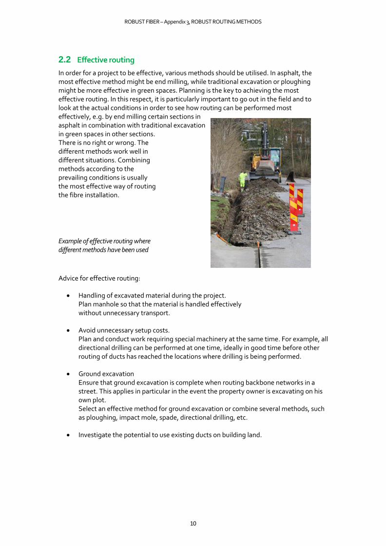
In order for a project to be effective, various methods should be utilised. In asphalt, the most effective method might be end milling, while traditional excavation or ploughing might be more effective in green spaces. Planning is the key to achieving the most effective routing. In this respect, it is particularly important to go out in the field and to look at the actual conditions in order to see how routing can be performed most effectively, e.g. by end milling certain sections in asphalt in combination with traditional excavation in green spaces in other sections. There is no right or wrong. The different methods work well in different situations. Combining methods according to the prevailing conditions is usually the most effective way of routing the fibre installation.
Example of effective routing where different methods have been used
Advice for effective routing:
• Handling of excavated material during the project. Plan manhole so that the material is handled effectively without unnecessary transport.
• Avoid unnecessary setup costs. Plan and conduct work requiring special machinery at the same time. For example, all directional drilling can be performed at one time, ideally in good time before other routing of ducts has reached the locations where drilling is being performed.
• Ground excavation Ensure that ground excavation is complete when routing backbone networks in a street. This applies in particular in the event the property owner is excavating on his own plot. Select an effective method for ground excavation or combine several methods, such as ploughing, impact mole, spade, directional drilling, etc.
• Investigate the potential to use existing ducts on building land.

ROBUST FIBER – Appendix 3, ROBUST ROUTING METHODS
11
3. GENERAL INFORMATION FOR A FIBRE PROJECT
3.1 Staking / cable indication query
Local regulations and procedures determine how staking and cable indication queries are to take place and be ordered through Appendix 8 Ledningskollen and any other local procedures.
Staking is conducted by the party that owns cables or by its appointed representative. Alternatively, the cable owner supplies data for the staking of existing cables. It is the contractor’s responsibility to determine the exact position of the cable before staring excavation.
As part of improving collaboration between network owners, authorities, cable operators and other players in the industry, a collaboration project "Grävallvar" is also being run with the aim of reducing digging damage on the cable networks (https://gravallvar.se/).
3.2 Prior survey on site
Before starting work, a survey should be conducted on site alongside the client (controller), contractor and land owner/road operator. An analysis is conducted of the work area’s surface layer along those sections where earthworks are planned, as well as in locations where outdoor splice cabinets, cable manholes and technical shelters are intended to be placed (Site). The analysis is reported and documented with film and photographs. The report is attached to the prepared land agreement. Well documented material facilitates surveys after implementation.
3.3 Collocation
The potential for collocation should be investigated and in certain cases may also be demanded by the land owner/road operator. This is an effective method, as several parties can share the excavation cost. Specific terms and conditions apply in the event of collocation, and agreement regarding these terms and conditions is reached between the parties on a case-by-case basis. The minimum requirements regarding collocation must be in accordance with “Instructions for Robust Fiber” or higher. Ensure that the correct material is used and that routing is performed correctly by the contractor.
3.4 Permits and land issues
In order to route cables in a municipality, the client (network owner) must enter into a land agreement with the local authority. This regulates aspects such as permission to route cables in municipal land, restoration and future maintenance.
For areas outside of municipal land where cables pass, a land agreement must be entered into with the relevant land owner. The network owner is responsible for obtaining land agreements. The network owner may engage another party to carry out this work, e.g. the contractor.

ROBUST FIBER – Appendix 3, ROBUST ROUTING METHODS
12
Different stakeholders can administer permits differently and have different requirements regarding e.g. the information that is to be attached with the application for a permit. Rules are regulations are often local and differ depending on where in the country they apply as well as who is issuing the permit (e.g. authority, land owner or road operator).
Examples of the requisite permits and agreements that may be required in a project:
• General land agreement with the local authority regarding the right to have cables in municipal land.
• Land agreements with private land owners. Govern the right to bury cables in the ground. Various types of land agreements occur, such as land lease agreements, usufruct agreements and utility easements.
• Permits/decisions regarding excavating from municipal and/or state road operators (Permission from the Swedish Transport Administration regarding the placement of telecommunication lines /track owners (railway)/land owners, which describe where new cables should be located, restoration requirements as well as the duration of the cable work.
In certain cases, these may need to be supplemented with a start permit (opening notification) from the land owner/road operator, e.g. a local authority or a road association/community.
• Cable location from land owner, e.g. local authority, Swedish Transport Administration or road operator. Regulates where the cable is to be located.
• Collocation agreement with another cable owner. Regulates the terms and conditions for collocation.
• Approved TA plan. For the Swedish Transport Administration see Permission for the
placement of telecommunication lines.
• Permission from the Swedish Transport Administration regarding the placement of telecommunication lines. The conditions for traffic and protective devices are obtained together with the decision on Permission for the placement of telecommunication lines.
• Consultation with the Country Administrative Board and/or the local authority regarding culture and the environment.
• This applies for example at watercourses, archaeological sites, alleys, unsuitable land, unique vegetation, cultural monuments, nature reserves, etc.
Agreement templates can be obtained from e.g. the Federation of Swedish Farmers, the Swedish Broadband Forum and Byanätsforum.
In general, all those who work on or beside roads must have received approved training “Work on Roads” – Level 1.
Local authorities and land owners often have different regulations that must be followed.

ROBUST FIBER – Appendix 3, ROBUST ROUTING METHODS
13
Some items that often differ between different land owners/road operators and that have to be checked by the parties in each contract are:
• Handling of restoration requirements, e.g. - layer thickness - type of material - type of fraction - local regulations - references to national regulations and sector requirements (AMA, TRVK, etc.). - who has to carry out the restoration and the size of the areas to be restored.
• Local requirements regarding routing depth and backfill height. • Permitted routing methods/excavation methods for the contract. • Charges for future maintenance. • Whether charges exist for the duration of the cable work, as well as for each permit
application that is submitted in respect of excavation and TA plans. • Whether planned standard-raising measures exist (asphalt laying programme) in the area
where the cable work is to be performed. • Ongoing charges for the right to route cables in municipal land, often as a sum per year
and metre of laid cable.
• Handling of restoration that is performed long after the work has been carried out, e.g. asphalt and grass in the winter.
3.5 TA plan
A traffic arrangement plan (TA plan) includes details about roadworks and how they are to be signalled. The TA plan regulates which road signs, road closures and protective arrangements are to be present at the road work site, and must include sketches regarding how the contractor should create a safe workplace for road users and personnel. A precondition for being able to carry out work on roads is that the road management authority has approved the TA plan. The Roads Act, which deals with public roads, construction and operation, states that measures may not be carried out within a road area without the permission of the road management authority.
A TA plan must be drawn up in accordance with regulations from private, municipal or national road operators and in accordance with applicable legal requirements. For the Swedish Transport Administration, the requirements for traffic and protective devices are set out in a conditional appendix to the decision on Permission for the placement of telecommunication lines. All those who work within a road or street area must always ensure that there is a TA plan for the workplace, and that it has been drawn up in accordance with applicable permits and legal requirements.
3.6 Work environment
The principal (client or network owner) has basic responsibility for the work environment. Responsibility for the work environment may be delegated to another party by agreement. In the case of a fibre installation project, the network owner may agree in writing with a contractor regarding taking over the role of principal. The principal is responsible for appointing a Construction work environment coordinator for planning and design (BAS-P) and a Construction work environment coordinator for execution (BAS-U). The principal is also responsible, together with the BAS-P, for drawing up a Work environment plan. The Work environment plan must be present at the workplace and all those who work at the site must be aware of the Work environment plan and must know where it is.

ROBUST FIBER – Appendix 3, ROBUST ROUTING METHODS
14
3.7 Environment
Machinery and vehicles must be environmentally classified, approved, CE marked and inspected.
The Swedish Transport Agency is responsible for matters relating to exhaust regulations, noise regulations for work machines and provisions regarding vehicle fuel. The exhaust requirements for tractors and work machines have been introduced jointly in the EU. These rules are set out in directives 97/68/EC (for work machines) and 2000/25/EC (for tractors). The directive for work machines also covers small, petrol-driven engines for e.g. lawn mowers, chainsaws, etc.
Environmental considerations must be a factor when choosing the fibre routing method. A few things to consider:
• Minimise transport of e.g. excavated material and relocation of machinery. • Plan the storage of excavated material during the project in order to reduce transport. • If possible, select machinery with low emissions. • Contaminated excavated material must be transported to a landfill site. • The work area must be kept clean and any soiling must be prevented. Waste water,
clay, concrete or chemicals may not be diverted to storm drains.
• Sort residual products at source and make sure that land and water are not contaminated with petrol, oil or equivalent.
• Contractors are responsible for cleaning streets/roads that have been soiled due to the work. • Bear in mind noise levels, particularly in the case of machinery that is stationed at the
same location for an extended period, e.g. compressors. • Exercise vigilance during activities that generate a large amount of dust.
In certain areas and cities there are specific environmental requirements, e.g. when working for the Swedish Transport Administration and within Stockholm, Gothenburg and Malmö. Always check applicable local rules and regulations.
Some routing methods are more effective from an environmental perspective than others. Skanova has ordered a masters dissertation, which has been carried out by Shan Solivan at the Royal Institute of Technology. The work can be found here: Life Cycle Assessment on fibre cable construction methods http://kth.diva-portal.org/smash/get/diva2:839631/FULLTEXT01.pdf
The conclusion is that the method with the least potential environmental impact is ploughing in green spaces, and it is generally best to avoid routing in asphalt. In asphalt, the methods that produce the least excavated material are the most environmentally friendly, such as groove cutting.
ROBUST FIBER – Appendix 3, ROBUST ROUTING METHODS
15
3.8 Subsequent survey on site
When the fibre installation is completed and restoration of the work area has been conducted, a new survey is conducted on site by representatives of the client and the contractor, as well as affected land owners/road operators. The representative of the client should contact affected land owners/road operators before this takes place in order to obtain any opinions about how the contractor has conducted the implementation and restoration. The review is reported and documented with film and photographs in order to demonstrate any differences between before and after execution. The report is signed by the relevant land owner and the Inspector attaches the report to the final inspection report.
3.9 Warranties
Local regulations for restoration vary between different local authorities, land owners and road operators. Always check applicable local rules and regulations.
With certain land owners, the contractor itself can perform the restoration and then provides a warranty. At others, the land owner itself will conduct restoration, and the client will often also have to pay a fee for future maintenance.
The warranty period is regulated in AB 04 General conditions of contract for building and civil engineering works and building services, Chapter 4 Section 7, as well as ABT 06 General conditions of contract for design and construct contracts for building, civil engineering and installation works, Chapter 4 Section 7.
AB 04 states that the Warranty period is 5 years for the contractor’s work performance and 2 years for materials and goods.
ABT 06 states that the Warranty period is 5 years for the contract. For specific material or specific goods (makes) prescribed by the client, the Warranty period is 2 years. However, these terms in AB 04 / ABT 06 can be changed in agreements, so other warranty periods may apply in individual cases.
3.10 Consultation with County Administrative Board
According to Chapter 12 Section 6 of the Environmental Code, specific instructions regarding consultation must be followed when working in natural and cultural areas. This applies for example at watercourses, archaeological sites, alleys, unsuitable land, unique vegetation, cultural monuments, nature reserves, etc. Consultation according to Chapter 12 Section 6 of the Environmental Code is handled by the County Administrative Boards. More information can be obtained from the Country Administrative Board in the relevant county.

ROBUST FIBER – Appendix 3, ROBUST ROUTING METHODS
16
3.11 Drainage in farmland
When routing in farmland, particular consideration must be given to the drainage in the land. Prior to excavation, the land owner must be asked about the depth at which the land’s drainage is located and must specify the depth at which the fibre installation’s ducts may be routed. This is particularly important when ploughing, as it is difficult to see whether existing drainage is damaged during the work.
3.12 Trees, roots and vegetation
Local regulations must be complied with, although it is generally not permitted to excavate within a tree’s drip zon. The principal is responsible for trees and plants that are affected by the work not sustaining damage.
• When working close to roots or other vegetation, it is important to take care. Manual excavation or suction excavation should ideally be used when there is a risk of damaging vegetation.
• Avoid compacting and driving heavy vehicles close to trees. • Avoid storing material close to trees.
Trees or bushes may not be felled without the land owner’s consent. Any required pruning of trees and bushes must be carried out in a professional manner.
ROBUST FIBER – Appendix 3, ROBUST ROUTING METHODS
17
4 EXCAVATION-FREE METHODS
4.1 Microtrenching
Also known as micro-ditching or groove cutting.
Minimum requirements in the case of microtrenching:
• The contractor must define the depth of existing infrastructure, ideally performed using ground-penetrating radar or physical inspection by means of excavation.
• Backfill height in accordance with “Instructions for Robust Fiber”
4.1.1 Method
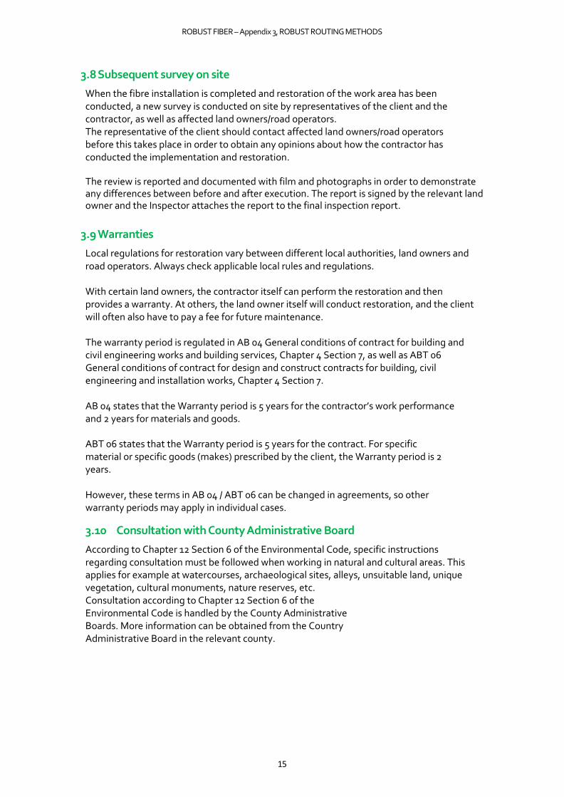
The machine has a unit with a sawblade which, at a high blade rotation speed, cuts through the surface layer and underlying layers. The outer edge of the sawblade comprises segments containing diamonds. The material that is cut away is broken down into sand/dust. This method requires careful staking and planning, as everything in the sawblade’s way is cut off. Ground-penetrating radar must be used before the machine, or a physical inspection by means of excavation must be performed before starting the work, to ensure that there is no risk of damaging existing cables.
Example of ground-penetrating radar
4.1.2 Machinery
Specially adapted machinery with a unit for the sawblade. A trailer carrying duct (drums) is normally used, which is pulled after the machine. A smaller cutting machine that departs from the main line in towards properties.
Compacting machine when refilling with sand. The machine has a wheel that is guided in the cut groove and uses pressure to compact the refill material in the groove. When refilling with foam concrete (aerated concrete), a special machine is used to perform refilling. No compaction is required when the cut groove is filled with foam concrete.
A sweeping machine may be required to clean the asphalt around the cut groove prior to sealing. Machine for sealing (bitumen pot) the cut groove.
4.1.3 Tools
Sawblades are available in various dimensions. For example, a sawblade with a diameter of 1 m can cut to a depth of approx. 38 cm.

ROBUST FIBER – Appendix 3, ROBUST ROUTING METHODS
18
Blade diameter Excavation depth
(approximate) 800 mm 28 cm
900 mm 32 cm
1000 mm 38 cm
Examples of sawblades
4.1.4 Suitable environment
Hardened surface (asphalt). Also works well in rock to some extent.
4.1.5 Advantages
• Little impact on the street, resulting in small road closures.
• Suitable for large excavation lengths in asphalted surfaces.
• Rapid routing, which ensure less disruption for residents and road users.
• Can be used all year round and also works well in frozen ground. This method actually works better in frozen ground, as there is less risk of material falling down into the cut groove when it is frozen.
• Can route microducts without problems. As the groove is narrow, there are more or less no problems routing microducts flat.
4.1.6 Restrictions (Disadvantages)
• Large turning radius when cutting with blade.
• Small wheels on the machine can damage the ground.
• The method can give off a lot of dust.
• The method is noisy.
• Stipulates considerable demands regarding staking.
• An excavator may be required at intersections with other cables, as well as when positioning cabinets/manholes.
• The narrow cut groove limits the number of microducts that can be routed in the same groove before reaching the ceiling for the backfill height.
4.1.7 Excavation
The cut groove is 15–30 mm wide, depending on the width of the sawblade. The excavation depth is up to approx. 40 cm and is dependent on the diameter of the sawblade. Examples of excavations

ROBUST FIBER – Appendix 3, ROBUST ROUTING METHODS
19
4.1.8 Excavated material
The excavated material is turned into finely crushed sand or rock dust. The material is placed to one side and swept up, before then being removed.
4.1.9 Duct bedding
There is no duct bedding. The bottom is sufficiently smooth without duct bedding.
4.1.10 Backfilling
Backfill must comprise 2–5 mm of dry sand. Foam concrete (aerated concrete) is also used as backfill material. In the winter, refrigerant is mixed with the foam concrete to prevent freezing.
4.1.11 Refilling
Refilling must comprise 2–5 mm of dry sand, which is compacted in the cut groove. Foam concrete (aerated concrete) is also used for refilling.
4.1.12 Restoration
The surface is restored using bitumen in the cut groove. Asphalting is not required.
Example of restoration after microtrenching
4.1.13 Environmental impact
Relatively small machines and rapid routing produce low emissions. A small volume of excavated material needing to be transported to/from the routing site results in low emissions from transport.
Work environment:
• This method is dusty and noisy.
4.1.14 Duct type
Smaller ducts in dimensions up to approx. 18 mm. Routing of single ducts (individual microducts) works well as the cut groove is narrow, and there is consequently little risk of the ducts not ending up flat.
4.1.15 Duct routing
Ducts are routed with a duct layer directly from the machine. Drums holding duct may be present on the machine or on a trailer being pulled after the machine.
ROBUST FIBER – Appendix 3, ROBUST ROUTING METHODS
20
Search wire is laid in the bottom or directly above the ducting. Marking mesh or other marking (e.g. coloured concrete) is laid in the refill material above the ducts.
4.2 End milling
Also known as infratrenching or minitrenching Minimum requirements regarding end milling:
• Ground-penetrating radar must be used or a physical inspection by means of excavation.
• Backfill height in accordance with Instructions for Robust Fiber.
4.2.1 Method
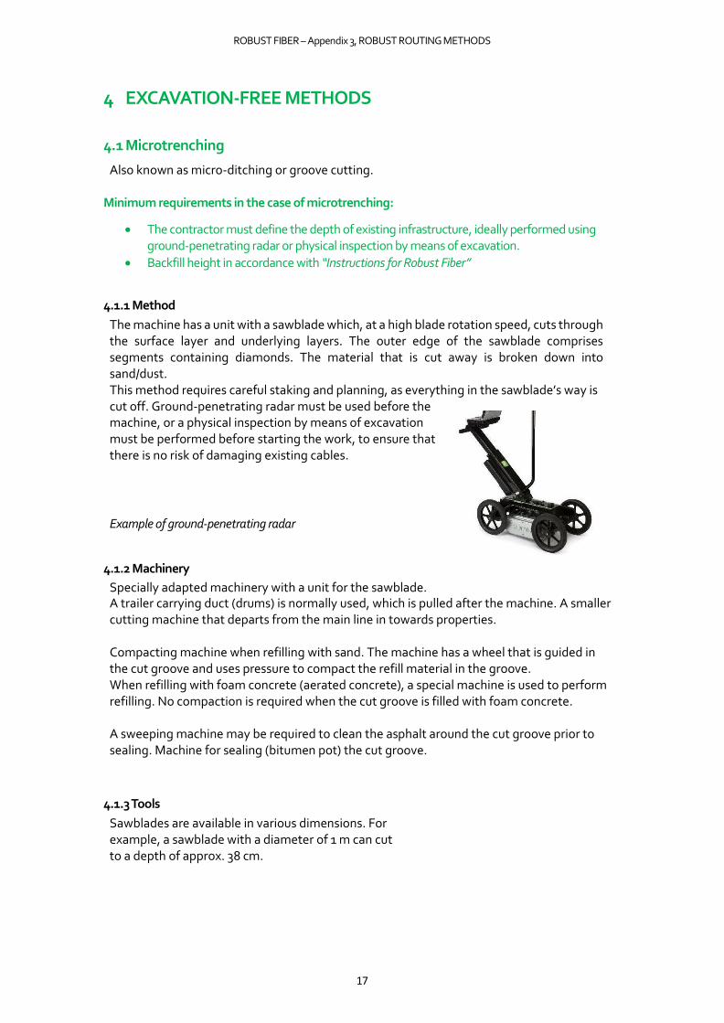
The ground is milled with a milling wheel with carbide bits. The machine has a unit with a milling wheel that rotates at a relatively low speed. The milling wheel passes through the surface layer and underlying layers. The material that is milled away is broken down into gravel/sand. This method requires careful staking and planning, as everything in the milling wheel’s way is cut off. Ground-penetrating radar must be used before the machine, or a physical inspection by means of excavation must be performed before starting the work, to ensure that there is no risk of damaging existing cables.
Example of end milling
4.2.2 Machinery
Specially adapted machinery with a unit for the milling wheel. Alternatively, an excavator with the unit mounted on the excavator’s arm is used. A trailer carrying duct (drums) is normally used, which is pulled after the machine. A smaller cutting machine that departs from the main line in towards properties. Machine for refilling. The excavated material from the milling operation is normally reused for refilling. Compacting machine with compacting wheel is used to compact the refill material. The machine has a wheel that is guided in the milled groove and uses pressure to compact the material in the groove. Face mill for milling down the asphalt edge alongside the milled groove in order to obtain a better attachment surface when laying asphalt on top. A sweeping machine may be required to clean the surface prior to asphalting. Machine for asphalting and bonding the asphalt edge.

ROBUST FIBER – Appendix 3, ROBUST ROUTING METHODS
21
Example of machine with milling wheel
4.2.3 Tools
Milling wheel with carbide bits. Milling wheels are available in various dimensions. For example, a milling wheel with a diameter of 1 m can mill down approx. 38 cm. A suitable milling wheel size for FTTH is a diameter of 0.8–1.4 m.
Milling wheel diameter
Excavation depth (approximate)
800 mm 28 cm
900 mm 32 cm
1000 mm 38 cm
Examples of milling wheel
4.2.4 Suitable environment
Hardened surface such as asphalt. Gravel roads and green spaces also work well. The method can also be used in soft soil types.
4.2.5 Advantages
• Little impact on the street, resulting in small road closures.
• Suitable for large excavation lengths in asphalted surfaces.
• Rapid routing which produces less disruption for residents and road users.
• Can be used all year round and also works well in frozen ground. The method actually works better in frozen ground, as there is less risk of material falling down into the milled groove when it is frozen.
ROBUST FIBER – Appendix 3, ROBUST ROUTING METHODS
22
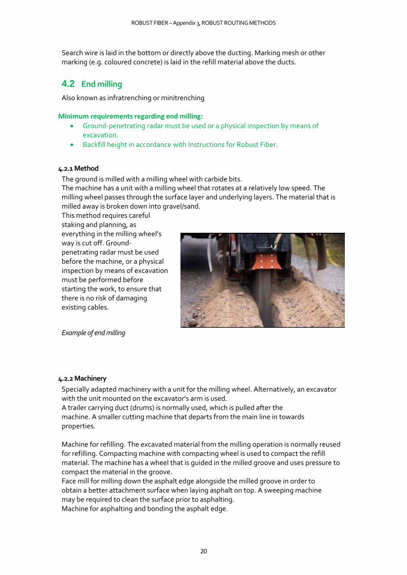
• Can route a large number of ducts of various dimensions.
• Possible to conduct collocation with other cable owners, e.g. street lighting.
• Also works well when turning around e.g. street corners.
Example of end milling around a street corner
4.2.6 Restrictions (Disadvantages)
• Risk of stones spraying up, depending on ground conditions. The edge of the asphalt can then be destroyed.
• Face milling around the milled groove is required in order for restoration to be successful.
• Edge cutting of asphalt edges may be required after milling.
• The method can give off a lot of dust.
• The method is noisy.
• Places considerable demands for staking (ground-penetrating radar must be used or physical inspection by means of excavation before starting work).
• An excavator may be required at intersections with other cables, as well as when positioning cabinets/manholes.
4.2.7 Excavation
The milled groove is approx. 28–150 mm wide and is dependent on the width of the milling wheel. The excavation depth is up to approx. 45 cm and is dependent on the diameter of the milling wheel.
4.2.8 Excavated material
The material is placed to one side of the milled groove and reused for refill. Stones are removed and new backfill material is obtained.
4.2.9 Duct bedding
There is no duct bedding. The bottom is sufficiently smooth without duct bedding.
4.2.10 Backfilling
Excavated material is normally reused as backfill. May need to be supplemented with 0–18 mm rock dust.
ROBUST FIBER – Appendix 3, ROBUST ROUTING METHODS
23
4.2.11 Refilling
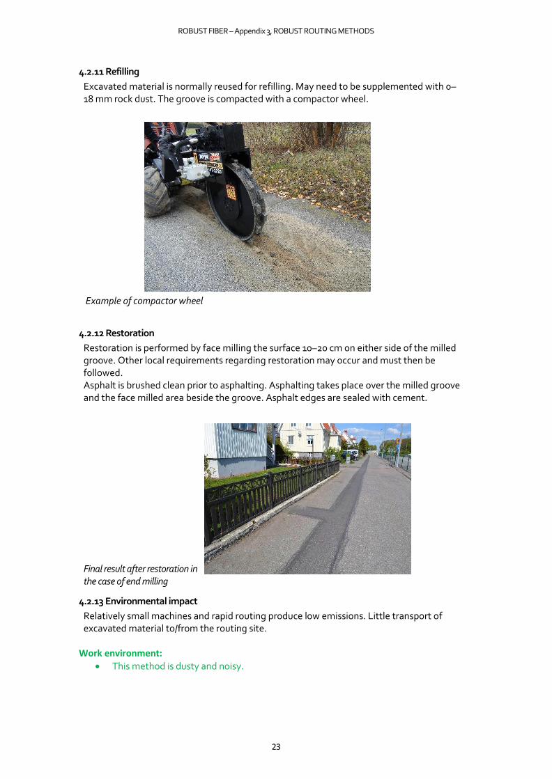
Excavated material is normally reused for refilling. May need to be supplemented with 0–18 mm rock dust. The groove is compacted with a compactor wheel.
Example of compactor wheel
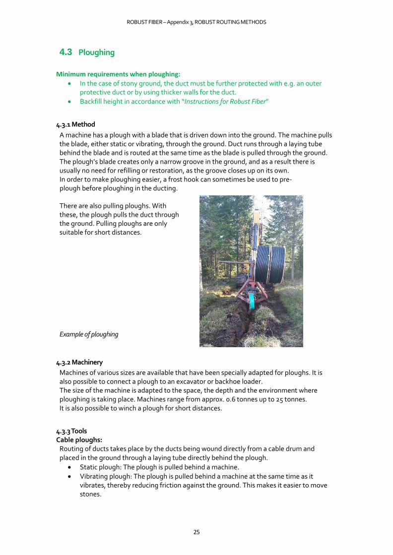
4.2.12 Restoration
Restoration is performed by face milling the surface 10–20 cm on either side of the milled groove. Other local requirements regarding restoration may occur and must then be followed. Asphalt is brushed clean prior to asphalting. Asphalting takes place over the milled groove and the face milled area beside the groove. Asphalt edges are sealed with cement.
Final result after restoration in the case of end milling
4.2.13 Environmental impact
Relatively small machines and rapid routing produce low emissions. Little transport of excavated material to/from the routing site.
Work environment:
• This method is dusty and noisy.

ROBUST FIBER – Appendix 3, ROBUST ROUTING METHODS
24
4.2.14 Duct type
All dimensions of ducts up to approx. 110 mm. Less suitable for single ducts (microducts) over extended distances due to the width of the milled groove. There is a risk of single ducts ending up in waves, which can make fibre blowing more difficult. This method is more suitable when routing multi-ducts.
4.2.15 Duct routing
Ducts are routed with a duct layer directly from the machine. Drums holding duct may be present on the machine or on a trailer being pulled after the machine. Ducts can also be routed manually in the milled groove after milling.
Search wire is laid in the bottom or above the duct. Marking mesh is placed in the refill material above the ducts.
ROBUST FIBER – Appendix 3, ROBUST ROUTING METHODS
25
4.3 Ploughing
Minimum requirements when ploughing:
• In the case of stony ground, the duct must be further protected with e.g. an outer protective duct or by using thicker walls for the duct.
• Backfill height in accordance with “Instructions for Robust Fiber”
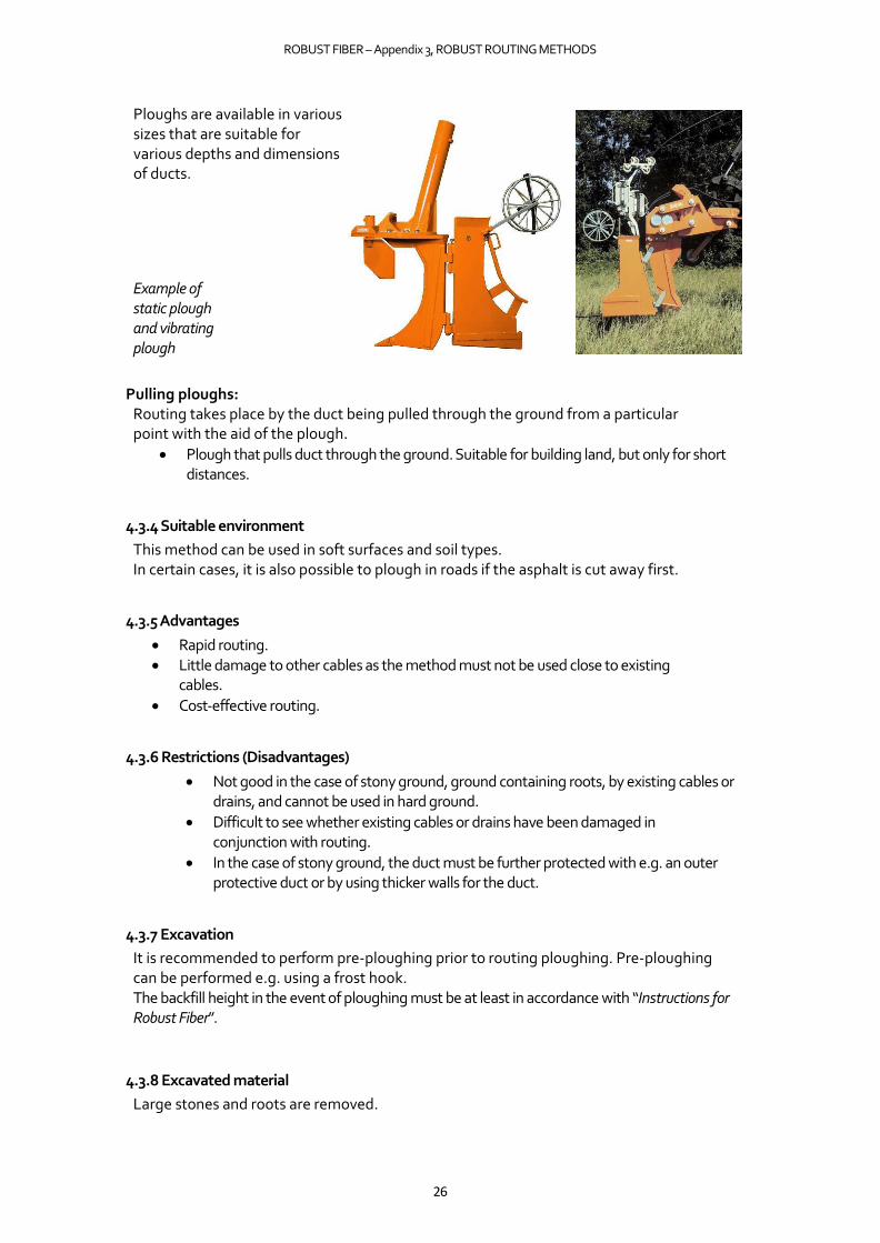
4.3.1 Method
A machine has a plough with a blade that is driven down into the ground. The machine pulls the blade, either static or vibrating, through the ground. Duct runs through a laying tube behind the blade and is routed at the same time as the blade is pulled through the ground. The plough’s blade creates only a narrow groove in the ground, and as a result there is usually no need for refilling or restoration, as the groove closes up on its own. In order to make ploughing easier, a frost hook can sometimes be used to pre-plough before ploughing in the ducting.
There are also pulling ploughs. With these, the plough pulls the duct through the ground. Pulling ploughs are only suitable for short distances.
Example of ploughing
4.3.2 Machinery
Machines of various sizes are available that have been specially adapted for ploughs. It is also possible to connect a plough to an excavator or backhoe loader. The size of the machine is adapted to the space, the depth and the environment where ploughing is taking place. Machines range from approx. 0.6 tonnes up to 25 tonnes. It is also possible to winch a plough for short distances.
4.3.3 Tools Cable ploughs:
Routing of ducts takes place by the ducts being wound directly from a cable drum and placed in the ground through a laying tube directly behind the plough.
• Static plough: The plough is pulled behind a machine.
• Vibrating plough: The plough is pulled behind a machine at the same time as it vibrates, thereby reducing friction against the ground. This makes it easier to move stones.
ROBUST FIBER – Appendix 3, ROBUST ROUTING METHODS
26
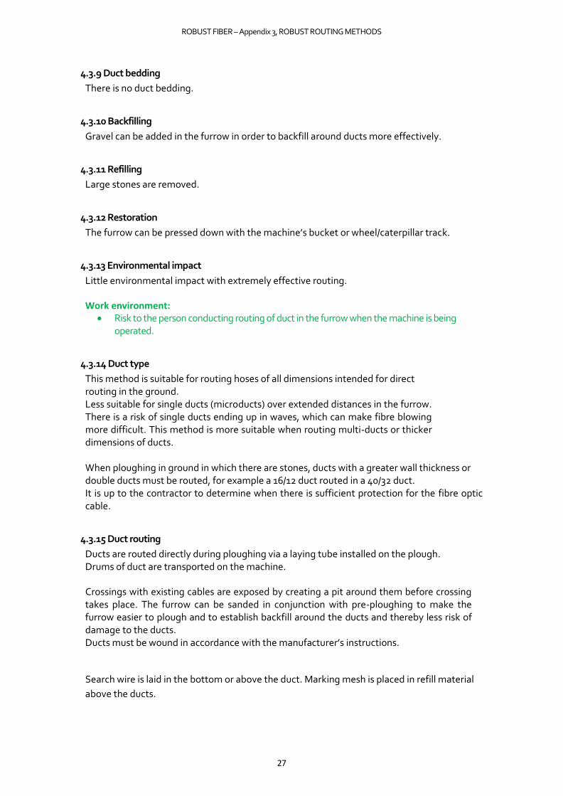
Ploughs are available in various sizes that are suitable for various depths and dimensions of ducts.
Example of static plough and vibrating plough
Pulling ploughs: Routing takes place by the duct being pulled through the ground from a particular point with the aid of the plough.
• Plough that pulls duct through the ground. Suitable for building land, but only for short distances.
4.3.4 Suitable environment
This method can be used in soft surfaces and soil types. In certain cases, it is also possible to plough in roads if the asphalt is cut away first.
4.3.5 Advantages
• Rapid routing. • Little damage to other cables as the method must not be used close to existing
cables.
• Cost-effective routing.
4.3.6 Restrictions (Disadvantages)
• Not good in the case of stony ground, ground containing roots, by existing cables or drains, and cannot be used in hard ground.
• Difficult to see whether existing cables or drains have been damaged in conjunction with routing.
• In the case of stony ground, the duct must be further protected with e.g. an outer protective duct or by using thicker walls for the duct.
4.3.7 Excavation
It is recommended to perform pre-ploughing prior to routing ploughing. Pre-ploughing can be performed e.g. using a frost hook. The backfill height in the event of ploughing must be at least in accordance with “Instructions for Robust Fiber”.
4.3.8 Excavated material
Large stones and roots are removed.
ROBUST FIBER – Appendix 3, ROBUST ROUTING METHODS
27
4.3.9 Duct bedding
There is no duct bedding.
4.3.10 Backfilling
Gravel can be added in the furrow in order to backfill around ducts more effectively.
4.3.11 Refilling
Large stones are removed.
4.3.12 Restoration
The furrow can be pressed down with the machine’s bucket or wheel/caterpillar track.
4.3.13 Environmental impact
Little environmental impact with extremely effective routing.
Work environment: • Risk to the person conducting routing of duct in the furrow when the machine is being
operated.
4.3.14 Duct type
This method is suitable for routing hoses of all dimensions intended for direct routing in the ground. Less suitable for single ducts (microducts) over extended distances in the furrow. There is a risk of single ducts ending up in waves, which can make fibre blowing more difficult. This method is more suitable when routing multi-ducts or thicker dimensions of ducts.
When ploughing in ground in which there are stones, ducts with a greater wall thickness or double ducts must be routed, for example a 16/12 duct routed in a 40/32 duct. It is up to the contractor to determine when there is sufficient protection for the fibre optic cable.
4.3.15 Duct routing
Ducts are routed directly during ploughing via a laying tube installed on the plough. Drums of duct are transported on the machine.
Crossings with existing cables are exposed by creating a pit around them before crossing takes place. The furrow can be sanded in conjunction with pre-ploughing to make the furrow easier to plough and to establish backfill around the ducts and thereby less risk of damage to the ducts. Ducts must be wound in accordance with the manufacturer’s instructions.
Search wire is laid in the bottom or above the duct. Marking mesh is placed in refill material
above the ducts.
ROBUST FIBER – Appendix 3, ROBUST ROUTING METHODS
28
4.4 Chain excavation Also known as milling excavation. Minimum requirements in the case of chain excavation:
• Backfill height in accordance with “Instructions for Robust Fiber”
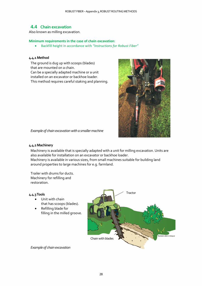
4.4.1 Method
The ground is dug up with scoops (blades) that are mounted on a chain. Can be a specially adapted machine or a unit installed on an excavator or backhoe loader. This method requires careful staking and planning.
Example of chain excavation with a smaller machine
4.4.2 Machinery
Machinery is available that is specially adapted with a unit for milling excavation. Units are also available for installation on an excavator or backhoe loader. Machinery is available in various sizes, from small machines suitable for building land around properties to large machines for e.g. farmland.
Trailer with drums for ducts. Machinery for refilling and restoration.
4.4.3 Tools
• Unit with chain that has scoops (blades).
• Refilling blade for filling in the milled groove.
Example of chain excavation
Tractor
Chain with blades

ROBUST FIBER – Appendix 3, ROBUST ROUTING METHODS
29
4.4.4 Suitable environment
This method works well in soft soil types, e.g. building land around properties, fields, along forest roads, etc.
4.4.5 Advantages
• Rapid routing.
• Potential to see damaged drains and cables (compared to ploughing).
• Potential to route a large number of ducts of various dimensions.
• Good method for collocation with other cable owners.
4.4.6 Restrictions (Disadvantages)
• Risk of stones spraying up, depending on ground conditions (personal injury).
• The method is noisy.
• Does not work in stony ground, moraine, rock, asphalt or hard surfaces.
• An excavator may be required at intersections with other cables, as well as when positioning cabinets/manholes.
4.4.7 Excavation
The excavated trench is between 100–250 mm wide. Depending on the machine, the excavation depth is up to approx. 100 cm (there are machines that can manage considerably deeper).
4.4.8 Excavated material
Placed to one side and used for refilling. Stones are transported away.
4.4.9 Duct bedding
Not normally required as the bottom is smooth.
4.4.10 Backfilling
Excavated material is normally reused as backfill.
4.4.11 Refilling
Excavated material is normally reused for refilling.
4.4.12 Restoration
The excavated material is pushed back into the excavated trench, which is then compacted by the machine.
4.4.13 Environmental impact
Rapid routing with relatively small machines and little need for transport results in low emissions.
Work environment:
• The method is noisy.
• Risk of stones spraying up.
ROBUST FIBER – Appendix 3, ROBUST ROUTING METHODS
30
4.4.14 Duct type
All dimensions up to approx. 110 mm. Less suitable for single ducts (microducts) over extended distances in the milled groove. There is a risk of single ducts ending up in waves, which can make fibre blowing more difficult. This method is more suitable when routing multi-ducts or thicker dimensions of ducts.
4.4.15 Duct routing
Can be routed with a duct layer directly from the machine. Drums on the machine or on a following trailer. Ducts can also be routed manually after the machine.
Search wire is laid in the bottom or above the duct. Marking mesh is placed in refill material above the ducts.
ROBUST FIBER – Appendix 3, ROBUST ROUTING METHODS
31
4.5 Suction excavation
Minimum requirements in the case of suction excavation:
• Backfill height in accordance with “Instructions for Robust Fiber”
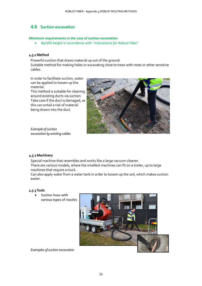
4.5.1 Method
Powerful suction that draws material up out of the ground. Suitable method for making holes or excavating close to trees with roots or other sensitive cables.
In order to facilitate suction, water can be applied to loosen up the material. This method is suitable for cleaning around existing ducts via suction. Take care if the duct is damaged, as this can entail a risk of material being drawn into the duct.
Example of suction excavation by existing cables
4.5.2 Machinery
Special machine that resembles and works like a large vacuum cleaner. There are various models, where the smallest machines can fit on a trailer, up to large machines that require a truck. Can also apply water from a water tank in order to loosen up the soil, which makes suction easier.
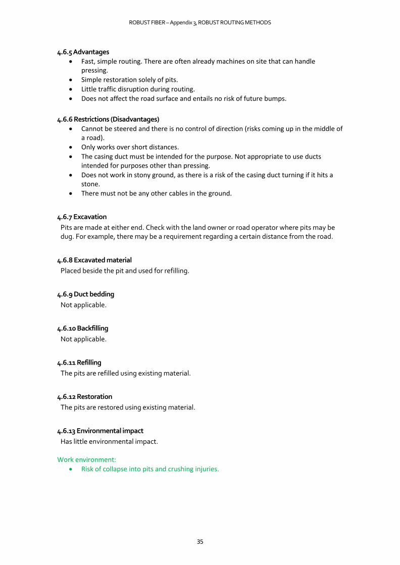
4.5.3 Tools
• Suction hose with various types of nozzles
Examples of suction excavation

ROBUST FIBER – Appendix 3, ROBUST ROUTING METHODS
32
4.5.4 Suitable environment
Only works in soft soil types. Excellent method around sensitive ducts (gas, electricity, water, etc.), roots and close to building walls. Can suction up material following other methods, e.g. in the case of microtrenching.
4.5.5 Advantages
• Good method when positioning cabinets and manholes.
• Easy to collect excavated material.
• Excavation around sensitive cables, roots and vegetation.
• Good for making small excavation holes or pits.
• Suitable for cleaning existing ducts and manholes.
4.5.6 Restrictions (Disadvantages)
• Difficult if the material is too coarse.
• Does not work in frozen ground.
• The size of the container limits the amount that can be suctioned up before emptying is required.
4.5.7 Excavation
Excavation is performed by means of suction through a nozzle. The nozzle can be changed for different needs. Used to make holes or suction around other cables or roots.
4.5.8 Excavated material
Ends up in a container that is installed on/by the machine.
4.5.9 Duct bedding
Not applicable.
4.5.10 Backfilling
Not applicable.
4.5.11 Refilling
Excavated material is used for refilling. Emptied from the machine back into the hole.
4.5.12 Restoration
Restoration of pit by means of refilling.

ROBUST FIBER – Appendix 3, ROBUST ROUTING METHODS
33
4.5.13 Environmental impact
The environmental impact is small with relatively small machines. Work environment:
• This method is relatively noisy.
4.5.14 Duct type
Can be used when positioning cabinets and manholes.
4.5.15 Duct routing
Not a method for routing ducts.

ROBUST FIBER – Appendix 3, ROBUST ROUTING METHODS
34
4.6 Pressing
Can also be referred to as auger boring (auger pressing).
Minimum requirements when pressing:
• Backfill height in accordance with “Instructions for Robust Fiber”
4.6.1 Method
Presses a steel duct (casing duct or protective duct) from one point to another. The casing duct remains in the ground and ducts are then placed in it. This method works well up to approx. 15 metres. It is not possible to steer or change direction during pressing. A bank or pit is required at either end in order to access with the machine.
Example of auger boring
4.6.2 Machinery
For smaller dimensions and short distances, e.g. under a wall, an excavator with a normal bucket or a specially adapted tool for pressing will work. Specially adapted rigs designed solely for pressing are also available, as shown above. Usually used in large dimensions.
4.6.3 Tools
Casing duct made of steel that is pressed through the ground. Diameters of up to approx. 200 mm are available for fibre installations. Casing ducts are available in several different dimensions. Avoid using ducts that are not intended for use as casing ducts.
4.6.4 Suitable environment
Soft soil types. Works well under small roads, pedestrian and cycle paths, under walls, etc.
Casing pipe augher anvil
ROBUST FIBER – Appendix 3, ROBUST ROUTING METHODS
35
4.6.5 Advantages
• Fast, simple routing. There are often already machines on site that can handle pressing.
• Simple restoration solely of pits.
• Little traffic disruption during routing.
• Does not affect the road surface and entails no risk of future bumps.
4.6.6 Restrictions (Disadvantages)
• Cannot be steered and there is no control of direction (risks coming up in the middle of a road).
• Only works over short distances.
• The casing duct must be intended for the purpose. Not appropriate to use ducts intended for purposes other than pressing.
• Does not work in stony ground, as there is a risk of the casing duct turning if it hits a stone.
• There must not be any other cables in the ground.
4.6.7 Excavation
Pits are made at either end. Check with the land owner or road operator where pits may be dug. For example, there may be a requirement regarding a certain distance from the road.
4.6.8 Excavated material
Placed beside the pit and used for refilling.
4.6.9 Duct bedding
Not applicable.
4.6.10 Backfilling
Not applicable.
4.6.11 Refilling
The pits are refilled using existing material.
4.6.12 Restoration
The pits are restored using existing material.
4.6.13 Environmental impact
Has little environmental impact. Work environment:
• Risk of collapse into pits and crushing injuries.

ROBUST FIBER – Appendix 3, ROBUST ROUTING METHODS
36
4.6.14 Duct type
Ducts in the casing duct in dimensions up to approx. 110 mm.
4.6.15 Duct routing
Duct is pushed or pulled through the casing duct.
It is recommended to fill the casing duct with ducts immediately after
installation. Search wire is routed in the casing duct.

ROBUST FIBER – Appendix 3, ROBUST ROUTING METHODS
37
4.7 Impact mole
Minimum requirements when routing with an impact mole:
• Backfill height in accordance with “Instructions for Robust Fiber”
4.7.1 Method
Compressed air-driven impact mole with a piston that drives the mole through the ground. The compressed air hose follows along behind the impact mole. Duct can be pulled along directly behind the impact mole or the impact mole can be reversed with duct from the other direction. Suitable for short distances up to approx. 15 metres. A pit is dug first at either end. The impact mole is then placed in one pit and targeted at the other pit. It is important to target correctly from the outset in order to end up in the pit at the other end, as the impact mole cannot be steered.
Routing with impact mole
4.7.2 Machinery
• Compressor for driving.
• Excavator for digging pits.
Example of impact mole with peripheral equipment
4.7.3 Tools
Impact moles are available in diameters ranging from approx. 50 mm up to approx. 150 mm. The length varies from approx. 700 mm up to approx. 1500 mm.
In order to route a 110 mm duct, a 130 mm impact mole is required.

ROBUST FIBER – Appendix 3, ROBUST ROUTING METHODS
38
Example of impact mole
4.7.4 Suitable environment
Soft soil types. Works well over short distances such as under pedestrian and cycle paths, walls, building land around properties, under paved garage entrances and patios, etc. Larger impact moles can be operated in coarser material. The smaller the impact mole, the finer the material. As a rule of thumb, the routing depth must be at least 10 times the diameter of the impact mole.
4.7.5 Advantages
• Fast and simple method.
• The shortest route can be selected.
• There are often machines already on site.
• Simple, minimal restoration.
• Does not affect the road surface (no future bumps).
4.7.6 Restrictions (Disadvantages)
• Cannot be steered.
• Not possible to measure the depth.
• Not possible to route marking mesh at a distance above ducts.
• Must not be used close to other cables.
• Can create bump in the ground surface if routed too shallow.
• Does not work in stony ground.
4.7.7 Excavation
Pits at either end.
4.7.8 Excavated material
Used for refill material in the pits.
4.7.9 Duct bedding
Not applicable.
4.7.10 Backfilling
Not applicable.
4.7.11 Refilling
Excavated material in pits.
ROBUST FIBER – Appendix 3, ROBUST ROUTING METHODS
39
4.7.12 Restoration
Only restoration of pits.
4.7.13 Environmental impact
Little environmental impact as only pits are dug. Work environment:
• Risk of collapse into pits.
4.7.14 Duct type
Works well for ducts up to approx. 110 mm.
4.7.15 Duct routing
Duct can be pulled directly behind the impact mole or the impact mole can be reversed and pull duct on the way back. A good method is to pull a thicker duct directly with the impact mole. A microduct is then placed in the thicker duct, and fibre optic cable is blown into the microduct.
Search wire is laid along with ducts. Marking mesh is pulled along and laid above the
ducts.
ROBUST FIBER – Appendix 3, ROBUST ROUTING METHODS
40
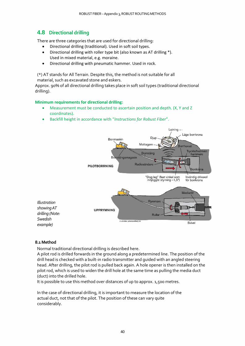
4.8 Directional drilling
There are three categories that are used for directional drilling: • Directional drilling (traditional). Used in soft soil types.
• Directional drilling with roller type bit (also known as AT drilling *). Used in mixed material, e.g. moraine.
• Directional drilling with pneumatic hammer. Used in rock.
(*) AT stands for All Terrain. Despite this, the method is not suitable for all material, such as excavated stone and eskers.
Approx. 90% of all directional drilling takes place in soft soil types (traditional directional drilling). Minimum requirements for directional drilling:
• Measurement must be conducted to ascertain position and depth. (X, Y and Z coordinates).
• Backfill height in accordance with “Instructions for Robust Fiber”.
Illustration showing AT drilling (Note: Swedish example)
8.1 Method
Normal traditional directional drilling is described here. A pilot rod is drilled forwards in the ground along a predetermined line. The position of the drill head is checked with a built-in radio transmitter and guided with an angled steering head. After drilling, the pilot rod is pulled back again. A hole opener is then installed on the pilot rod, which is used to widen the drill hole at the same time as pulling the media duct (duct) into the drilled hole. It is possible to use this method over distances of up to approx. 1,500 metres.
In the case of directional drilling, it is important to measure the location of the actual duct, not that of the pilot. The position of these can vary quite considerably.

ROBUST FIBER – Appendix 3, ROBUST ROUTING METHODS
41
Example of directional drilling (Note: Swedish example)
4.8.2 Machinery
• Special drilling machines for horizontal directional drilling. The size of the machine is measured in terms of pulling force (tonnes).
• Excavator for pits.
• Truck with mixer and pump for drilling fluid (bentonite slurry).
• Sludge suction device for suctioning drilling fluid.
• Compressor (for pneumatic hammer).
Example of directional drilling
4.8.3 Tools
Different tools depending on drilling method.
• Different drill bits depending on method, e.g. roller type bit.
• Drilling head (steering head)
• Hole opener
• Pneumatic hammer
• Search tools for determining position during drilling
• DGPS for measuring position in XYZ axes.
Example of drill bit

ROBUST FIBER – Appendix 3, ROBUST ROUTING METHODS
42
Pilot rod with steering head Hope opener installed on pilot rod
Example of directional drilling when the media duct (duct) is pulled back with a hole opener.
4.8.4 Suitable environment
• Directional drilling (traditional) in soft soil types.
• Directional drilling with roller type bit / AT drilling in mixed material, e.g. moraine.
• Directional drilling with pneumatic hammer in rock.
This method is very suitable for use when passing under roads, watercourses, railways, sensitive environments (parks, trees, nature areas, near animals, archaeological sites). Very well suited for creating land attachments when routing in lakes and watercourses.
4.8.5 Advantages
• Drilling below farmland in order not to disturb the layers of soil.
• When crossing roads to ensure little disruption and no impact on the surface layer.
• Drilling beneath sensitive areas (plants, animals, parks, etc.).
• Possible to conduct routing without a water court ruling when drilling below the bottom of watercourses.
• Rapid routing.
• Small drilling rigs suitable on building land.
• Collocation with other cable owners.
Media pipe Pilot rod
ROBUST FIBER – Appendix 3, ROBUST ROUTING METHODS
43
4.8.6 Restrictions (Disadvantages)
• Expensive setup cost for short distances and individual drilling operations. • Ducts cannot be accessed afterwards if drilling performed at depth. • Stipulates demands regarding ducting dimensions (tensile strength) in the case of
extended distances. • Considerable demands regarding location of other cables. • Severe cold, as the drilling fluid freezes below approx. -15°C. • The machine and pits take up a relatively large amount of space. • Handling drilling fluid that should be collected.
4.8.7 Excavation
Pits are required at either end. The size and depth of the pits depends on the type of machine being used and the incline and depth of drilling. It is possible to drill approx. 500–700 mm below a hardened surface (asphalted) and below roadbeds without affecting the surface layer.
4.8.8 Excavated material
Reused for refilling.
4.8.9 Duct bedding
Not applicable.
4.8.10 Backfilling
Not applicable.
4.8.11 Refilling
Refilling of pits with existing material.
4.8.12 Restoration
Restoration of pits.
4.8.13 Environmental impact
Little in relation to other methods. Possible to avoid long excavation distances where excavations have previously detoured around obstacles.
Work environment
• The method is noisy.
• Risk of collapse into pits.
ROBUST FIBER – Appendix 3, ROBUST ROUTING METHODS
44
4.8.14 Duct type
All lengths and dimensions. Requires considerable tensile strength for ducts over extended distances.
4.8.15 Duct routing
Duct is pulled back after drilling with pilot rod.
Search wire is laid along with ducts.
Marking mesh is laid above the ducts.

ROBUST FIBER – Appendix 3, ROBUST ROUTING METHODS
45
4.9 Hammer drilling Also known as casing drilling. Minimum requirements for hammer drilling:
• Measurement must be conducted to ascertain position and depth. (X, Y and Z coordinates).
4.9.1 Method
A compressed air-driven hammer drills through the rock and pulls along a casing (protective duct). This method is dry, i.e. no drilling fluid is required. Used from diameters of approx. 130 mm up to approx. 1200 mm. Casings are made of steel and form the outermost ducting, in which ducts are then routed.
4.9.2 Machinery
• Horizontal beam with counterhold and powerful compressor. Often a specially built machine.
• A truck with a crane is required to lift the machine into place.
• Excavator for pits at either end.
4.9.3 Tools
Down-the-hole hammer (piston hammer) that strikes a pilot bit.
Drilling rig
Pilot bit drill Hammer
Pilot bit drill
Drilling rig
PILOT DRILLING
Pilot hole Hammer BROACHING
Broach crown

ROBUST FIBER – Appendix 3, ROBUST ROUTING METHODS
46
Example of hammer drilling. (Note: Swedish example)
4.9.4 Suitable environment
Works well in solid rock, moraine, excavated stone and in land containing boulders.
4.9.5 Advantages
• Passes through most things, apart from steel.
4.9.6 Restrictions (Disadvantages)
• Cannot be steered. • The max. length is approx. 40 m. • Long setup time prior to drilling. • Large pits at the ends.
4.9.7 Excavation
Pits at either end.
4.9.8 Excavated material
Reused for refilling pits. Gravel excavated from the drill hole is transported away or used for refilling pits. The volume is approx. 1.7 times larger than the volume of the drill hole.
4.9.9 Duct bedding
Not applicable.
4.9.10 Backfilling
Not applicable.
4.9.11 Refilling
Refilling of pits with existing material.
ROBUST FIBER – Appendix 3, ROBUST ROUTING METHODS
47
4.9.12 Restoration
Restoration of pits.
4.9.13 Environmental impact
Work environment:
• The method is noisy.
• When drilling in pure rock, a large amount of dust can be created.
• Risk of collapse into pits.
4.9.14 Duct type
All dimensions up to approx. 110 mm.
4.9.15 Duct routing
Duct is pushed or pulled through the casing. Search wire and marking mesh are placed in the
casing.

ROBUST FIBER – Appendix 3, ROBUST ROUTING METHODS
48
5 EXCAVATION METHODS
5.1 Excavation with excavator (Traditional excavator)
Minimum requirements for excavation:
• Backfill height in accordance with “Instructions for Robust Fiber”.
5.1.1 Method
An excavator with a bucket digs a trench, a particular section, or just a pit. The excavated material is placed alongside or transported away. Local rules and regulations exist regarding the handling of excavated material and must be complied with.
In the trench, duct bedding is created on which ducts are placed. The trench is then refilled and the surface is restored according to applicable procedures and regulations.
The method is used for positioning manholes and cabinets.
5.1.2 Machinery
Machines are available with wheels or tracks (caterpillar). Machines with wheels are normally used on hardened surfaces in order not to damage the surface. The excavator may have a trailer for handling excavated material. The size of the machine is adapted to the space and the environment where excavation is taking place. Machines range from approx. 0.6 tonnes up to approx. 25 tonnes. Different types of machines are available, such as backhoe loaders that provide considerable flexibility, as well as revolving excavators that have high excavation capacity and are available with wheels or tracks.
Machine for edge-cutting of asphalt. Truck for transporting excavated material.
5.1.3 Tools
A number of different buckets suitable for various types of excavation are available for excavators. Examples of buckets: cable bucket, meshred bucket, depth bucket and grading bucket. Tools for cable routing should not have teeth in order to reduce the risk of damage to existing cables.
Examples of buckets
5.1.4 Suitable environment
This method can be used in all types of open trenches and surfaces. Not in solid rock.
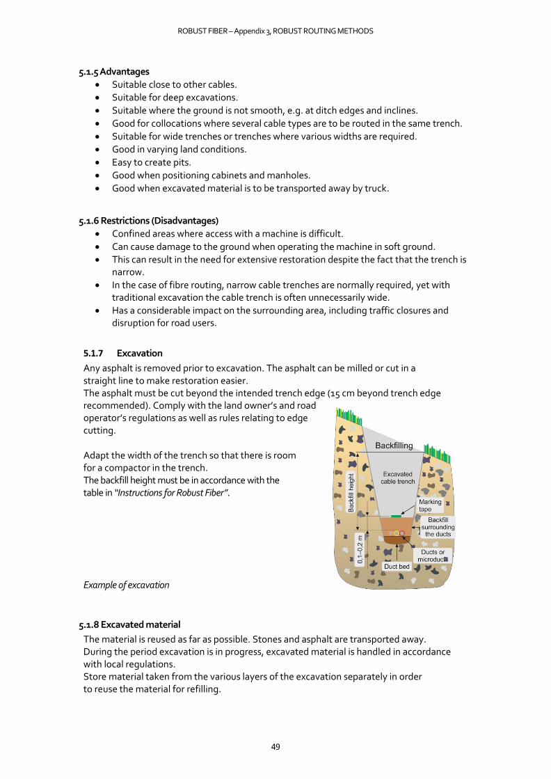
ROBUST FIBER – Appendix 3, ROBUST ROUTING METHODS
49
5.1.5 Advantages
• Suitable close to other cables.
• Suitable for deep excavations.
• Suitable where the ground is not smooth, e.g. at ditch edges and inclines.
• Good for collocations where several cable types are to be routed in the same trench.
• Suitable for wide trenches or trenches where various widths are required.
• Good in varying land conditions.
• Easy to create pits.
• Good when positioning cabinets and manholes.
• Good when excavated material is to be transported away by truck.
5.1.6 Restrictions (Disadvantages)
• Confined areas where access with a machine is difficult.
• Can cause damage to the ground when operating the machine in soft ground.
• This can result in the need for extensive restoration despite the fact that the trench is narrow.
• In the case of fibre routing, narrow cable trenches are normally required, yet with traditional excavation the cable trench is often unnecessarily wide.
• Has a considerable impact on the surrounding area, including traffic closures and disruption for road users.
5.1.7 Excavation
Any asphalt is removed prior to excavation. The asphalt can be milled or cut in a straight line to make restoration easier. The asphalt must be cut beyond the intended trench edge (15 cm beyond trench edge recommended). Comply with the land owner’s and road operator’s regulations as well as rules relating to edge cutting.
Adapt the width of the trench so that there is room for a compactor in the trench. The backfill height must be in accordance with the table in “Instructions for Robust Fiber”.
Example of excavation
5.1.8 Excavated material
The material is reused as far as possible. Stones and asphalt are transported away. During the period excavation is in progress, excavated material is handled in accordance with local regulations. Store material taken from the various layers of the excavation separately in order to reuse the material for refilling.
ROBUST FIBER – Appendix 3, ROBUST ROUTING METHODS
50
5.1.9 Duct bedding
Duct bedding must be flat and must comprise natural sand or rock dust with a grain size of 0–18 mm. Duct bedding with a thickness of at least 5 cm is recommended.
When positioning manholes, the manufacturer’s instructions must be followed. Duct bedding must also be present below manholes.
5.1.10 Backfilling
Backfill must comprise natural sand or rock dust with a grain size of 0–18 mm. Backfill with a thickness of at least 5 cm is recommended above the ducts. It is important to ensure that pockets do not form around the ducts. Compaction must take place after backfilling.
5.1.11 Refilling
Reuse excavated material as far as possible. Stones that risk being pressed against and damaging the ducts must be removed from the refill material prior to compacting. No clay material in the refill for roads or pedestrian and cycle paths.
5.1.12 Restoration
The ground must be restored to its original condition. Face milling of the surface beyond the width of the trench in asphalt may be required prior to re-asphalting.
5.1.3 Environmental impact
Any contaminated material that is discovered must be transported to a landfill site, e.g. asphalt.
Work environment:
• Risk to excavation technicians who are in the trench when the excavator is digging.
5.1.14 Duct type
This method is suitable for routing all types of ducts intended for direct routing in the ground. Less suitable for single ducts (microducts) over extended distances in the trench. There is a risk of single ducts ending up in waves, which can make fibre blowing more difficult. This method is more suitable when routing multi-ducts or thicker dimensions of ducts.
5.1.15 Duct routing
Ducts are routed at the bottom of the duct bedding. Ducts must be wound in accordance with the manufacturer’s instructions. Ducts must be kept straight and tensioned prior to refilling. Perform compaction prior to blowing in a fibre optic cable.
Search wire is laid in the bottom or above the duct. Marking mesh is placed in refill material
above the ducts.

ROBUST FIBER – Appendix 3, ROBUST ROUTING METHODS
51
5.2 Manual excavation
Minimum requirements when routing with manual excavation:
• Backfill height in accordance with “Instructions for Robust Fiber”
5.2.1 Method
A pit is dug by hand using e.g. a spade, and the excavated material is placed to the side of the pit. Ducts are installed in the trench, the land is refilled and restored. Excavation with a spade, crowbar or pickaxe does not require any machinery, only manual force. Machines may be used to refill and restore the pit.
5.2.2 Machinery
Manual.
5.2.3 Tools
Tools are available in several variants and for different purposes, e.g. spade, shovel, pointed hoe, pickaxe and crowbar.
Examples of tools
5.2.4 Suitable environment
This method can be used in soft surfaces. Used for example close to existing cables, close to house walls, by outdoor splice cabinets, on building land and when positioning cabinets and manholes.
5.2.5 Advantages
• Suitable close to other cables.
• Good in confined areas.
• Good in sensitive ground and close to vegetation.
• Suitable for small trenches.
• Good when positioning cabinets and manholes.
• Can be performed without prior knowledge.
5.2.6 Restrictions (Disadvantages)
• Difficult in the case of hard surfaces.
• Not possible in frozen ground.
• Not suitable for long distances.
•
5.2.7 Excavation
Flexible and easy to adapt.

ROBUST FIBER – Appendix 3, ROBUST ROUTING METHODS
52
5.2.8 Excavated material
Reuse excavated material as far as possible. During the period excavation is in progress, excavated material is handled in accordance with local regulations. Store material taken from the various layers of the excavation separately in order to reuse the material for refilling.
5.2.9 Duct bedding
Duct bedding must be flat and must comprise natural sand or rock dust with a grain size of 0–18 mm. Duct bedding with a thickness of at least 5 cm is recommended. When positioning manholes, the manufacturer’s instructions must be followed. Duct bedding must also be present below manholes.
5.2.10 Backfilling
Backfill must comprise natural sand or rock dust with a grain size of 0–18 mm. Backfill with a thickness of at least 5 cm is recommended above the ducts. It is important to ensure that pockets do not form around the ducts. Compaction must take place after backfilling.
5.2.11 Refilling
Reuse excavated material as far as possible. Stones that risk being pressed against and damaging the ducts must be removed from the refill material prior to compacting. No clay material in the refill for roads or pedestrian and cycle paths.
5.2.12 Restoration
The ground must be restored to its original condition.
5.2.13 Environmental impact
Very little environmental impact. Contaminated excavated material must be transported to a landfill site.
Work environment:
• Use ergonomically designed tools.
5.2.14 Duct type
This method is suitable for routing all types of ducts intended for direct routing in the ground as well as for positioning of cabinets and manholes.
5.2.15 Duct routing
Ducts are routed at the bottom of the duct bedding. Ducts must be wound in accordance with the manufacturer’s instructions. Ducts must be kept straight and tensioned prior to refilling.
Search wire is laid in the bottom or above the duct. Marking mesh is placed in refill material above the ducts.