INSTRUCTIONS FOR QUARTERLY MECHANICAL INTEGRITY ASSESSMENT OF
18
Form 5500-PM-OGXXXX Rev. 8/2013 COMMONWEALTH OF PENNSYLVANIA Instructions DEPARTMENT OF ENVIRONMENTAL PROTECTION OIL AND GAS MANAGEMENT PROGRAM - 1 - INSTRUCTIONS FOR QUARTERLY MECHANICAL INTEGRITY ASSESSMENT OF OPERATING OIL AND GAS WELLS – FORM A (DRAFT) (Form 5500-PM-OGXXXX) GENERAL INFORMATION The Mechanical Integrity Assessment Report is used to record quarterly well integrity data for operating oil and gas wells. Gas storage field wells, wells granted inactive status, and those regulated under the EPA’s UIC Program are subject to other mechanical integrity testing requirements and are, therefore, exempt from this monitoring program. For efficiency, two forms have been developed. Form A permits quarterly well integrity data to be compiled for up to 250 well locations for four consecutive quarters and has embedded computer programming. This programming is designed to indicate the required inspection elements for the well design under evaluation. To utilize these features as intended, it is essential that the form be populated sequentially in accordance with the numbered data fields. Additionally, Form A is only compatible with Microsoft Excel versions 2007 or later. The second form – Form B – is for operators/owners who are aware of the well inspection components that apply at their well locations and prefer assembling the well inspection data using other mechanisms. Form B allows for up to 6,000 individual inspections to be recorded. Quarterly reports for all operating oil and gas wells must be submitted to the Department by February 15 th of the year following the inspections to satisfy the reporting requirement in Section 78.88(e) of 25 Pa. Code Chapter 78. In addition to this annual reporting obligation, there are certain identified well conditions that do require immediate Department notification – these are detailed later in this document. Pennsylvania has experienced a long history of hydrocarbon development from reservoirs varying significantly in character. As such, many different operating well construction configurations exist. Because the Mechanical Integrity Assessment Report is used in conjunction with wells that vary substantially in both age and construction detail, and also due to the fact that multiple types of wells must be monitored as part of the program, instructions are provided to assure timely and accurate completion and submittal of reports. These instructions are intended to accompany Form A. All inspection data must be compiled and submitted electronically to the Harrisburg Bureau of Oil & Gas Planning & Program Management office to comply with the regulation. Hand-written inspection reports will not be accepted. Electronic submissions must be uploaded annually by the deadline at the Office of Oil and Gas Management’s MIA reporting web interface. Instructions for completing this process are provided on the website. For technical questions regarding inspection components, contact the appropriate DEP District Oil & Gas Operations office using the information that follows. A map denoting the counties that each District Oil & Gas Operations office is responsible for is included at the end of these instructions. PA DEP Northwest District Oil & Gas Operations Northwest Regional Office Phone 814.332.6860 230 Chestnut Street Fax 814.332.6121 Meadville, PA 16335-3481 PA DEP Southwest District Oil & Gas Operations Southwest Regional Office Phone 412.442.4024 400 Waterfront Drive Fax 412.442.4328 Pittsburgh, PA 15222-4745 PA DEP Eastern District Oil & Gas Operations North Central Regional Office Phone 570.327.3636 208 West Third Street Fax 570.327.3565 Williamsport, PA 17701-6448 If problems using the forms on your personal computer are encountered, or for questions about submitting well integrity data, please contact the Bureau of Oil & Gas Planning & Program Management in Harrisburg. PA DEP Bureau of Oil & Gas Planning & Program Management PO Box 8765 Phone 717.772.2199 Harrisburg, PA 17105-8765 Fax 717.772.2291
Transcript of INSTRUCTIONS FOR QUARTERLY MECHANICAL INTEGRITY ASSESSMENT OF
Form 5500-PM-OGXXXX Rev. 8/2013 COMMONWEALTH OF PENNSYLVANIA Instructions DEPARTMENT OF ENVIRONMENTAL PROTECTION OIL AND GAS MANAGEMENT PROGRAM
- 1 -
INSTRUCTIONS FOR QUARTERLY MECHANICAL INTEGRITY ASSESSMENT OF OPERATING OIL AND GAS WELLS – FORM A (DRAFT)
(Form 5500-PM-OGXXXX)
GENERAL INFORMATION The Mechanical Integrity Assessment Report is used to record quarterly well integrity data for operating oil and gas wells. Gas storage field wells, wells granted inactive status, and those regulated under the EPA’s UIC Program are subject to other mechanical integrity testing requirements and are, therefore, exempt from this monitoring program. For efficiency, two forms have been developed. Form A permits quarterly well integrity data to be compiled for up to 250 well locations for four consecutive quarters and has embedded computer programming. This programming is designed to indicate the required inspection elements for the well design under evaluation. To utilize these features as intended, it is essential that the form be populated sequentially in accordance with the numbered data fields. Additionally, Form A is only compatible with Microsoft Excel versions 2007 or later. The second form – Form B – is for operators/owners who are aware of the well inspection components that apply at their well locations and prefer assembling the well inspection data using other mechanisms. Form B allows for up to 6,000 individual inspections to be recorded. Quarterly reports for all operating oil and gas wells must be submitted to the Department by February 15
th of the
year following the inspections to satisfy the reporting requirement in Section 78.88(e) of 25 Pa. Code Chapter 78. In addition to this annual reporting obligation, there are certain identified well conditions that do require immediate Department notification – these are detailed later in this document. Pennsylvania has experienced a long history of hydrocarbon development from reservoirs varying significantly in character. As such, many different operating well construction configurations exist. Because the Mechanical Integrity Assessment Report is used in conjunction with wells that vary substantially in both age and construction detail, and also due to the fact that multiple types of wells must be monitored as part of the program, instructions are provided to assure timely and accurate completion and submittal of reports. These instructions are intended to accompany Form A.
All inspection data must be compiled and submitted electronically to the Harrisburg Bureau of Oil & Gas Planning & Program Management office to comply with the regulation. Hand-written inspection reports will not be accepted. Electronic submissions must be uploaded annually by the deadline at the Office of Oil and Gas Management’s MIA reporting web interface. Instructions for completing this process are provided on the website. For technical questions regarding inspection components, contact the appropriate DEP District Oil & Gas Operations office using the information that follows. A map denoting the counties that each District Oil & Gas Operations office is responsible for is included at the end of these instructions. PA DEP Northwest District Oil & Gas Operations Northwest Regional Office Phone 814.332.6860 230 Chestnut Street Fax 814.332.6121 Meadville, PA 16335-3481 PA DEP Southwest District Oil & Gas Operations Southwest Regional Office Phone 412.442.4024 400 Waterfront Drive Fax 412.442.4328 Pittsburgh, PA 15222-4745 PA DEP Eastern District Oil & Gas Operations North Central Regional Office Phone 570.327.3636 208 West Third Street Fax 570.327.3565 Williamsport, PA 17701-6448
If problems using the forms on your personal computer are encountered, or for questions about submitting well integrity data, please contact the Bureau of Oil & Gas Planning & Program Management in Harrisburg. PA DEP Bureau of Oil & Gas Planning & Program Management PO Box 8765 Phone 717.772.2199 Harrisburg, PA 17105-8765 Fax 717.772.2291

Form 5500-PM-OGXXXX Rev. 8/2013 Instructions
-2-
Form 5500-PM-OGXXXX, Mechanical Integrity Assessment Report, Quarterly Inspection Worksheet – FORM A INTRODUCTION To utilize this inspection program to its fullest potential, it is strongly encouraged that all inspections be conducted in a consistent manner. For example, to the extent possible, measurements should be acquired under the same conditions from quarter-to-quarter. This will enable operators/owners to determine if there is a significant change at a well that may be indicative of a well integrity problem. Additionally, all pressure and stabilized flow data should be measured with devices that are appropriately scaled for the expected range of values. There is no requirement to modify or retrofit wells drilled prior to February 5, 2011 to satisfy the regulations under Section 78.88 of 25 Pa. Code Chapter 78. The Department does encourage operators to maintain safe access to all annular spaces and generally considers this a best practice for all new wells drilled. However, it recognizes that many existing wells may not be configured this way and in such cases the operator must only complete as many of the applicable inspection components as the surface well configuration permits. Operators/owners may voluntarily choose to implement modifications at older wells, should they determine such changes are warranted; and the Department may ask for such changes to be made during the course of a water supply complaint investigation, should it determine that available well integrity data for any suspect well is limited and could be enhanced by surface modifications. Dates between individual quarterly inspections should be reasonably spaced in time. The Department recommends at least 45 days between consecutive quarterly inspections, but acknowledges that certain factors may prevent this from happening in all cases. If an inspection cannot be completed during any particular quarter due to legitimate changes in operations or because of well maintenance, this should be documented using the comments field on the form. Missing a quarterly monitoring event will limit some functionality built into Form A – namely the ability to transfer the previous quarter’s inspection data when conditions at the well have not changed. In these cases, it is still critical that a date be entered on the form in order to ensure that it functions as designed. For all sections of Form A, only those items within yellow-shaded boxes need to be completed. The blue-shaded boxes are optional inspection components not
required for compliance. In some cases they are also used to enable certain automated functions. The hatched boxes are not relevant for the well under evaluation. Finally, white boxes are automatically updated using the embedded computer programming. Form A is formatted to receive all four quarters of data for an individual well location in four consecutive rows. It is also programmed in a way that will only require operators to enter certain, static conditions at the well one time. To create a template capable of receiving subsequent years of data that preserves well construction information and other details, select the button near the top left-hand corner of the worksheet labeled “Create Template for Next Year.” DEFINITIONS Annular Production Casing: A string of casing in the wellbore, outside of the primary production casing, which is run for the purposes designated under either coal protective, surface, or intermediate casing; and as a means of confining or conducting hydrocarbons and associated fluids from one or more producing horizons to the surface. Coal Protective Casing: A string or strings of casing which are installed in the well for the purpose of coal segregation and protection. In some instances the coal protective casing and the surface casing may be the same. Hydrocarbon Production: Any hydrocarbons that are tied to a sales line, used for the generation of electricity/domestic gas, or used to operate pumps/other equipment in the vicinity of the well. Annular vent flows to the atmosphere are not considered produced gas. Intermediate Casing: A string of casing set after the surface casing and before production casing, not to include coal protective casing, that is used in the wellbore to isolate, stabilize or provide well control. Primary Production Casing: The final string of pipe in the wellbore, not including tubing or liners, which is run for the purpose of confining or conducting hydrocarbons and associated fluids from one or more producing horizons to the surface. Surface Casing: A string or strings of casing used to isolate the wellbore from fresh groundwater and to prevent the escape or migration of gas, oil or other fluids from the wellbore into fresh groundwater. The surface casing is also commonly referred to as the water string or water casing.
Form 5500-PM-OGXXXX Rev. 8/2013 Instructions
-3-
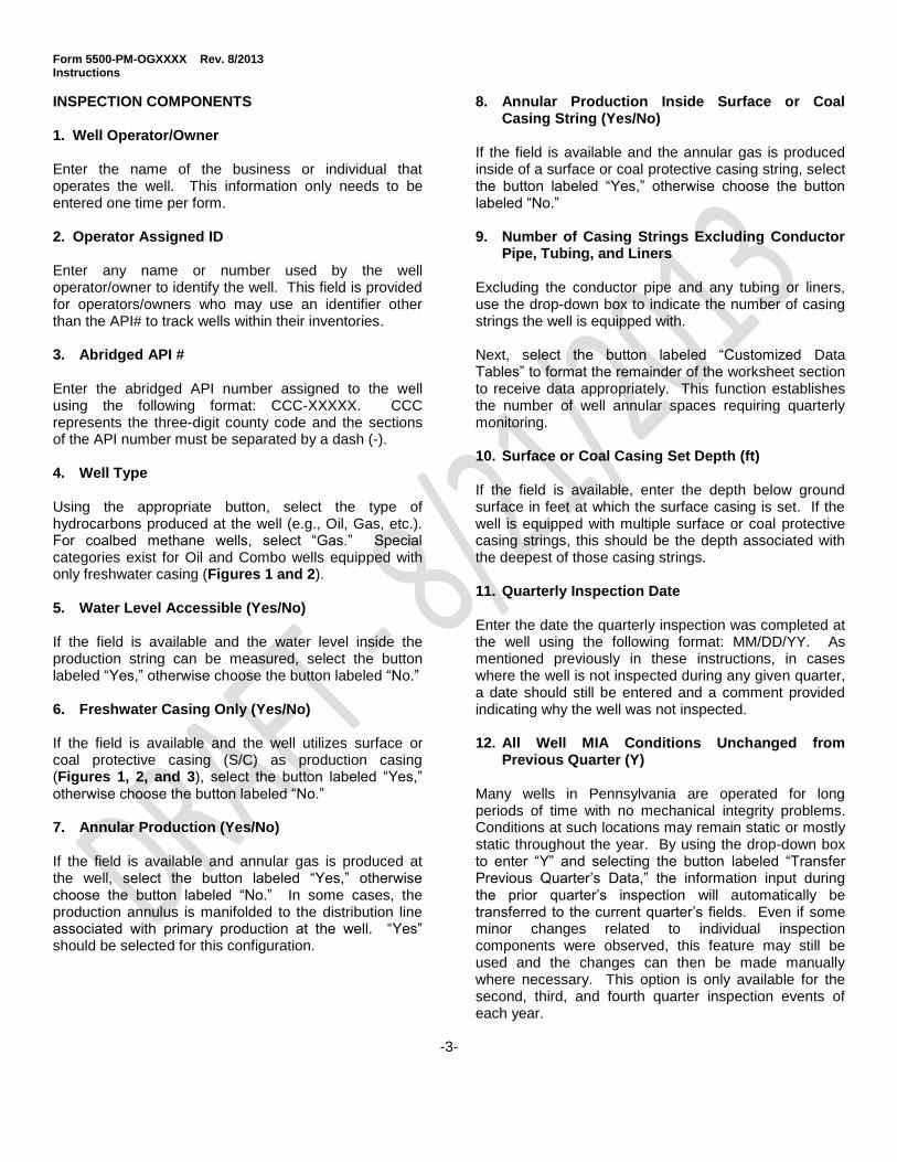
INSPECTION COMPONENTS 1. Well Operator/Owner Enter the name of the business or individual that operates the well. This information only needs to be entered one time per form. 2. Operator Assigned ID Enter any name or number used by the well operator/owner to identify the well. This field is provided for operators/owners who may use an identifier other than the API# to track wells within their inventories. 3. Abridged API # Enter the abridged API number assigned to the well using the following format: CCC-XXXXX. CCC represents the three-digit county code and the sections of the API number must be separated by a dash (-). 4. Well Type Using the appropriate button, select the type of hydrocarbons produced at the well (e.g., Oil, Gas, etc.). For coalbed methane wells, select “Gas.” Special categories exist for Oil and Combo wells equipped with only freshwater casing (Figures 1 and 2). 5. Water Level Accessible (Yes/No) If the field is available and the water level inside the production string can be measured, select the button labeled “Yes,” otherwise choose the button labeled “No.” 6. Freshwater Casing Only (Yes/No) If the field is available and the well utilizes surface or coal protective casing (S/C) as production casing (Figures 1, 2, and 3), select the button labeled “Yes,” otherwise choose the button labeled “No.” 7. Annular Production (Yes/No) If the field is available and annular gas is produced at the well, select the button labeled “Yes,” otherwise choose the button labeled “No.” In some cases, the production annulus is manifolded to the distribution line associated with primary production at the well. “Yes” should be selected for this configuration.
8. Annular Production Inside Surface or Coal Casing String (Yes/No)
If the field is available and the annular gas is produced inside of a surface or coal protective casing string, select the button labeled “Yes,” otherwise choose the button labeled “No.” 9. Number of Casing Strings Excluding Conductor
Pipe, Tubing, and Liners Excluding the conductor pipe and any tubing or liners, use the drop-down box to indicate the number of casing strings the well is equipped with. Next, select the button labeled “Customized Data Tables” to format the remainder of the worksheet section to receive data appropriately. This function establishes the number of well annular spaces requiring quarterly monitoring. 10. Surface or Coal Casing Set Depth (ft) If the field is available, enter the depth below ground surface in feet at which the surface casing is set. If the well is equipped with multiple surface or coal protective casing strings, this should be the depth associated with the deepest of those casing strings. 11. Quarterly Inspection Date Enter the date the quarterly inspection was completed at the well using the following format: MM/DD/YY. As mentioned previously in these instructions, in cases where the well is not inspected during any given quarter, a date should still be entered and a comment provided indicating why the well was not inspected. 12. All Well MIA Conditions Unchanged from
Previous Quarter (Y) Many wells in Pennsylvania are operated for long periods of time with no mechanical integrity problems. Conditions at such locations may remain static or mostly static throughout the year. By using the drop-down box to enter “Y” and selecting the button labeled “Transfer Previous Quarter’s Data,” the information input during the prior quarter’s inspection will automatically be transferred to the current quarter’s fields. Even if some minor changes related to individual inspection components were observed, this feature may still be used and the changes can then be made manually where necessary. This option is only available for the second, third, and fourth quarter inspection events of each year.

Form 5500-PM-OGXXXX Rev. 8/2013 Instructions
-4-
If conditions remain static or mostly static between the fourth quarter of the previous year and the first quarter of a new inspection year, the button labeled “Transfer 4
th
Qtr From Previous Year” can be used to transfer the inspection results from the fourth quarter of the previous inspection year to the first quarter of the current inspection year. This option will only work if the data from last year’s inspection are stored in the same Excel workbook and the prior year’s worksheet is named “Last_Years_Data,” which is the default name assigned when a new inspection template is generated. 13. Wellhead Pressure or Water Level §78.88(b)(1)
a. Primary Production Gas Pressure, pounds
per square inch gauge (psig)
If the field is available, enter the shut-in or producing back (flowing) pressure in psig inside the primary production string. Many wells are equipped with production tubing, and remediated wells may even have liners between the production casing and tubing. For the purposes of this integrity survey, pressure should only be reported for the outermost tubular associated with production from the deepest targeted formation – this is invariably the production casing string (Figures 2, 3, 4, and 6).
b. Produced Annular Gas Pressure (psig)
If the field is available, enter the shut-in or producing back (flowing) pressure in psig inside the annular production string (Figures 5 and 7). If only a single pressure gauge is available for all produced gas, enter the value provided under 13.a.
c. Shoe Test Pressure (psig) (OPTIONAL)
For annular gas produced inside of the intermediate casing string, the relevant shut-in or producing back (flowing) pressure threshold is the shoe test pressure. If the field is available, enter the shoe test pressure in psig, if known. d. Annulus
This field is automatically populated based on previously entered data. e. Water Level (ft)
If the field is available, enter the water level depth in feet below ground surface inside of the primary production casing string (Figures 1 and 2).
f. Average Daily Pumping Time (hours) (if no produced water, indicate “NA”)
For certain well designs, measuring the water level inside of the production casing is a requirement. However, this may be difficult to achieve without sophisticated meters or removing production equipment from the well. As an acceptable alternative to gauging the water level inside of the production string, an operator may instead provide the average daily pumping time in hours during the timeframe since the last quarterly inspection, if this field is available. Increases in pumping time may indicate additional sources of fluids in the wellbore associated with the failure of a component designed to provide zonal isolation. Some oil- and gas-bearing formations in Pennsylvania do not have associated produced water. If this is the case and this field is available, the operator should enter “NA” for not applicable. g. Produced Water Quality – Specific
Conductance (μS or μmhos/cm)
As an additional acceptable alternative to either gauging the water level inside of the primary production string or providing the average daily pumping time, an operator may instead test the produced water quality. If this field is available, enter the specific conductance of the produced water in micro-Siemens or micro-mhos per centimeter using a properly maintained and calibrated field meter. If multiple wells are plumbed to a single produced-water holding tank, a composite reading should be provided unless sample access ports are available between the well and the holding tank.
14. Flow or Pressure in Production Annulus
§78.88(b)(2) a. Production Annulus Status
If fields b. and c. in this section of Form A are available, use the appropriately labeled button to indicate if the production casing annulus is shut-in, venting, or inaccessible (Figures 1, 2, 3, 4, and 6). The status indicated may either be the status the annulus is routinely maintained in, or the status applied for the purposes of carrying out the quarterly inspection. For example, if an operator/owner chooses to shut-in a production annulus to conduct a pressure build-up test for an annulus that is

Form 5500-PM-OGXXXX Rev. 8/2013 Instructions
-5-
normally vented, the button labeled “Shut-In” should be selected.
b. Production Annulus Flow, standard cubic
feet per day (scfpd) If the field is available, enter the stabilized production annulus flow rate in scfpd. If the production annulus is not under the wellhead, which may be the case for older wells and for wells equipped with freshwater casing only, a best estimate of quantity of escaping gas should be provided. c. Production Annulus Pressure (psig)
If the field is available, indicate the production annulus pressure in psig. d. Time Since Production Annulus was Last
Blown Down (days) (OPTIONAL)
If the field is available, indicate the time in days since the production annulus was last blown down, if known.
e. Cement Top in Production Annulus Above
Next Outer Casing Shoe (Y/N) (OPTIONAL)
If the field is available, use the drop-down box to indicate “Y” if the cement in the production annulus is above the shoe of the next outer casing string defining the annular space. If the cement is below this casing string, i.e., there is an open-hole section associated with the production annulus, enter “N” (Figures 4 and 6). The cement top indicator entered on the form may be based on a volumetric calculation (i.e., the designed cement top). If the cement top was logged after placement, this number should be used to complete this field, as it is more reliable than a volumetric calculation. Log interpretations may vary, but for the purpose of this inspection, the highest section of the wellbore where cement was noted should be used to determine the input for this field, regardless of whether or not the bond between the cement and the wellbore or the cement and the production casing is only partial. f. Annulus This field is automatically populated based on previously entered data.
15. Best Estimate of Leaking/Venting Gas Quantity §78.88(b)(3) a. Annulus
If the field is available, use the drop-down box to enter the annulus inspected by referring to the nomenclature established in Figures 1 through 7. b. Flow (scfpd)
If the field is available, enter the flow rate in scfpd for the non-produced annulus indicated in 15.a.
c. Annulus Shut-in (Y/N/I) If the field is available, use the drop-down box to enter “Y” if the annulus in 15.a. is shut-in. If the designated annular space is not accessible due to the surface configuration of the well, enter “I;” otherwise enter “N.”
d. Annulus
If the field is available, use the drop-down box to enter the annulus inspected by referring to the nomenclature established in Figures 1 through 7.
e. Flow (scfpd)
If the field is available, enter the flow rate in scfpd for the non-produced annulus indicated in 15.d.
f. Annulus Shut-in (Y/N/I) If the field is available, use the drop-down box to enter “Y” if the annulus in 15.d. is shut-in. If the designated annular space is not accessible due to the surface configuration of the well, enter “I;” otherwise enter “N.” g. Annulus
If the field is available, use the drop-down box to enter the annulus inspected by referring to the nomenclature established in Figures 1 through 7.
h. Flow (scfpd)
If the field is available, enter the flow rate in scfpd for the non-produced annulus indicated in 15.g.

Form 5500-PM-OGXXXX Rev. 8/2013 Instructions
-6-
i. Annulus Shut-in (Y/N/I) If the field is available, use the drop-down box to enter “Y” if the annulus in 15.g. is shut-in. If the designated annular space is not accessible due to the surface configuration of the well, enter “I;” otherwise enter “N.”
j. Annulus If the field is available, use the drop-down box to enter the annulus inspected by referring to the nomenclature established in Figures 1 through 7.
k. Flow (scfpd)
If the field is available, enter the flow rate in scfpd for the non-produced annulus indicated in 15.j. l. Annulus Shut-in (Y/N/I) If the field is available, use the drop-down box to enter “Y” if the annulus in 15.j. is shut-in. If the designated annular space is not accessible due to the surface configuration of the well, enter “I;” otherwise enter “N.” m. Surface/Wellhead Equipment/Outside
Conductor (Y/N) Enter “Y” if any escaping gas is noted at the surface, in association with wellhead equipment, or outside of the conductor pipe, otherwise enter “N.”
16. Liquid Hydrocarbon Flows §78.88(a),
§78.81(a)(2) & 78.73(b) a. Annulus
If the field is available, use the drop-down box to enter the annulus inspected by referring to the nomenclature established in Figures 1 through 7.
b. (Y/N/I) If the field is available, use the drop-down box to enter “Y” if any uncontained, liquid hydrocarbon discharges at the surface capable of impacting environmental media are noted in association with the non-freshwater annulus in 16.a., or if any liquid hydrocarbon flows are noted in association with the freshwater annulus in 16.a. If the designated annular space is not accessible due to the surface configuration of the well, enter “I;” otherwise enter “N.”
c. Annulus If the field is available, use the drop-down box to enter the annulus inspected by referring to the nomenclature established in Figures 1 through 7. d. (Y/N/I) If the field is available, use the drop-down box to enter “Y” if any uncontained, liquid hydrocarbon discharges at the surface capable of impacting environmental media are noted in association with the non-freshwater annulus in 16.c., or if any liquid hydrocarbon flows are noted in association with the freshwater annulus in 16.c. If the designated annular space is not accessible due to the surface configuration of the well, enter “I;” otherwise enter “N.”
e. Annulus If the field is available, use the drop-down box to enter the annulus inspected by referring to the nomenclature established in Figures 1 through 7.
f. (Y/N/I) If the field is available, use the drop-down box to enter “Y” if any uncontained, liquid hydrocarbon discharges at the surface capable of impacting environmental media are noted in association with the non-freshwater annulus in 16.e., or if any liquid hydrocarbon flows are noted in association with the freshwater annulus in 16.e. If the designated annular space is not accessible due to the surface configuration of the well, enter “I;” otherwise enter “N.”
g. Annulus If the field is available, use the drop-down box to enter the annulus inspected by referring to the nomenclature established in Figures 1 through 7.
h. (Y/N/I) If the field is available, use the drop-down box to enter “Y” if any uncontained, liquid hydrocarbon discharges at the surface capable of impacting environmental media are noted in association with the non-freshwater annulus in 16.g., or if any liquid hydrocarbon flows are noted in association with the freshwater annulus in 16.g. If the designated annular space is not accessible due to the surface

Form 5500-PM-OGXXXX Rev. 8/2013 Instructions
-7-
configuration of the well, enter “I;” otherwise enter “N.”
i. Annulus If the field is available, use the drop-down box to enter the annulus inspected by referring to the nomenclature established in Figures 1 through 7. j. (Y/N/I) If the field is available, use the drop-down box to enter “Y” if any uncontained, liquid hydrocarbon discharges at the surface capable of impacting environmental media are noted in association with the non-freshwater annulus in 16.i., or if any liquid hydrocarbon flows are noted in association with the freshwater annulus in 16.i. If the designated annular space is not accessible due to the surface configuration of the well, enter “I;” otherwise enter “N.” k. Surface/Wellhead Equipment/Outside
Conductor (Y/N) Enter “Y” if any liquid hydrocarbon discharges capable of impacting environmental media are noted at the surface, in association with wellhead equipment, or outside of the conductor pipe, otherwise enter “N.”
17. Non-Freshwater Flows §78.88(a), §78.81(a)(2)
& 78.73(b)
For the purpose of this inspection, non-freshwater is any water having a specific conductance in excess of either 1,000 µS or µmhos/cm, or background water quality for the inspection area. a. Annulus
If the field is available, use the drop-down box to enter the annulus inspected by referring to the nomenclature established in Figures 1 through 7. b. (Y/N/I)
If the field is available, use the drop-down box to enter “Y” if any uncontained, non-freshwater discharges at the surface capable of impacting environmental media are noted in association with the non-freshwater annulus in 17.a., or if any non-freshwater flows are noted in association with the freshwater annulus in 17.a. If the designated annular space is not accessible due to the surface
configuration of the well, enter “I;” otherwise enter “N.”
c. Annulus
If the field is available, use the drop-down box to enter the annulus inspected by referring to the nomenclature established in Figures 1 through 7.
d. (Y/N/I)
If the field is available, use the drop-down box to enter “Y” if any uncontained, non-freshwater discharges at the surface capable of impacting environmental media are noted in association with the non-freshwater annulus in 17.c., or if any non-freshwater flows are noted in association with the freshwater annulus in 17.c. If the designated annular space is not accessible due to the surface configuration of the well, enter “I;” otherwise enter “N.”
e. Annulus
If the field is available, use the drop-down box to enter the annulus inspected by referring to the nomenclature established in Figures 1 through 7.
f. (Y/N/I)
If the field is available, use the drop-down box to enter “Y” if any uncontained, non-freshwater discharges at the surface capable of impacting environmental media are noted in association with the non-freshwater annulus in 17.e., or if any non-freshwater flows are noted in association with the freshwater annulus in 17.e. If the designated annular space is not accessible due to the surface configuration of the well, enter “I;” otherwise enter “N.”
g. Annulus
If the field is available, use the drop-down box to enter the annulus inspected by referring to the nomenclature established in Figures 1 through 7.
h. (Y/N/I)
If the field is available, use the drop-down box to enter “Y” if any uncontained, non-freshwater discharges at the surface capable of impacting environmental media are noted in association with the non-freshwater annulus in 17.g., or if any non-freshwater flows are noted in association with the

Form 5500-PM-OGXXXX Rev. 8/2013 Instructions
-8-
freshwater annulus in 17.g. If the designated annular space is not accessible due to the surface configuration of the well, enter “I;” otherwise enter “N.”
i. Annulus
If the field is available, use the drop-down box to enter the annulus inspected by referring to the nomenclature established in Figures 1 through 7.
j. (Y/N/I) If the field is available, use the drop-down box to enter “Y” if any uncontained, non-freshwater discharges at the surface capable of impacting environmental media are noted in association with the non-freshwater annulus in 17.i., or if any non-freshwater flows are noted in association with the freshwater annulus in 17.i. If the designated annular space is not accessible due to the surface configuration of the well, enter “I;” otherwise enter “N.”
k. Surface/Wellhead Equipment/Outside
Conductor (Y/N)
Enter “Y” if any uncontained, non-freshwater discharges capable of impacting environmental media are noted at the surface, in association with wellhead equipment, or outside of the conductor pipe, otherwise enter “N.”
18. Safe Venting §78.88(a), §78.74 & 78.77 For any wells where gas is escaping either through controlled annular venting or as a result of equipment leaks, it is critical to determine as soon as possible that venting is taking place safely. The procedure for doing so is described below and illustrated in Figure 8.
b. Wellhead Hydrogen Sulfide, parts per million
(ppm)
If the field is available, enter the highest level of hydrogen sulfide detected in parts per million while using a properly maintained and calibrated gas meter to monitor 360
O around the edge of the well
cellar/three (3) feet from the wellhead at a height of three (3) feet above the ground surface.
c. Wellhead Methane, percent of the Lower Explosive Limit (% LEL)
If the field is available, enter the highest % LEL reading detected while using a properly maintained and calibrated gas meter to monitor 360
O around the
edge of the well cellar/three (3) feet from the wellhead at a height of three (3) feet above the ground surface.
19. Corrosion Problems (Y/N) §78.88(b)(4) Visually inspect external above-ground well components, including the casing head, tubing head, studs and bolts, adapters, side outlet valves, tees and crosses on the Christmas tree, chokes, vent lines, stuffing box, conductor and other casing stumps accessible at the surface, and any other components designed to contain pressurized fluids or isolate any hydrocarbons or other non-freshwater fluids from environmental media, including soil, groundwater, or surface water. The above components shall be assessed for the presence of surface oxidation. Use the drop-down box to enter “Y” if any severe corrosion problems are noted that, unless repaired, will result in the imminent failure of well components intended to contain pressure or produced fluids, otherwise enter “N.” There is no expectation for operators/owners to address minor surface corrosion as part of this inspection, as the presence of some surface oxidation is actually beneficial to the integrity of operating wells.
20. Comments Please add any relevant comments or clarification regarding the quarterly inspection at the well. Entries are limited to 255 characters.
21. Immediate DEP Reporting Necessary (Y/N) For any cells that are shaded red and contain a “Y,” a potential well integrity problem exists as defined in 25 Pa. Code Section 78.88. These problems include overpressuring of the surface or coal casing seat in wells that use either of those casing strings as production casing, or severe corrosion as described previously in these instructions. Overpressuring is defined in 25 Pa. Code Section 78.73(c) as surface measured shut-in or producing back (flowing) pressures in excess of 80% x 0.433 psi/ft x length (ft) of the surface or coal protective casing being used as production casing. In these instances, it is necessary to report the issue to the

Form 5500-PM-OGXXXX Rev. 8/2013 Instructions
-9-
District Oil and Gas Inspector Supervisor within 24 hours of identifying the potential problem. It is possible that the well inspection will reveal other potential problems related to environmental protection or health and safety. Operators should follow all existing polices, laws, and regulations with regard to reporting these other problems to the Department. 22. Reset Section In certain cases when the information for a well is entered incorrectly and the operator/owner wishes to begin the set-up and data-entry process again, a “Y” should be entered under the column heading “9. Number of Casing Strings Excluding Conductor Pipe, Tubing, and Liners” below the red cell labeled “22. RESET SECTION (Y).” Once this is done, the button labeled “RESET” should be chosen and all of the data entered for the well will be erased and cell formatting will return to the default settings. THIS FUNCTION SHOULD BE APPLIED CAREFULLY, AS IT WILL DELETE ANY EXISTING WELL INTEGRITY DATA.

Form 5500-PM-OGXXXX Rev. 8/2013 Instructions
- 10 -
COMMONWEALTH OF PENNSYLVANIA – OIL & GAS OFFICES DEPARTMENT OF ENVIRONMENTAL PROTECTION
230 Chestnut Street Meadville, PA 16335-3481 814.332.6860
Oil and Gas Districts Northwest District
Southwest District Central Office
East District
208 West Third Street Williamsport, PA 17701-6448
570.321.6550
Bureau of Oil & Gas Planning & Program Management
PO Box 8765 Harrisburg, PA 17105-8765
717.772.2199
400 Waterfront Street Pittsburgh, PA 15222-4745 412.442.4024

-11-
Figure 1 – Schematic representing a typical oil well constructed using ONLY FRESHWATER CASING (OIL (FRESHWATER CASING ONLY)). The purple casing string represents the conductor pipe and the orange casing string represents the surface or coal protective casing. If the water level inside of the primary production casing (surface or coal protective) can be readily gauged, it should be gauged. Otherwise the average daily pumping time or produced water quality should be provided. The primary production annulus in this case is designated “S/C,” as it is outside of the deepest freshwater casing string. Inspection elements are indicated in green.
Section 13: Water Level or average
daily pumping time or produced
water quality measurement in field
Section 14: Primary Production
Annulus “S/C” (conductor x
surface) pressure (shut-in) or flow
(venting)
Produced Hydrocarbon Zone (Oil)
Sections 15, 16, and 17: Inspect
for surface discharges/annular
flows of gas, liquid hydrocarbons,
or non-freshwater
Tubing head may or may not be present
depending on how hydrocarbons and
other fluids are extracted at the well
Sections 18 and 19: Confirm safe
venting (if escaping gas is noted)
and complete corrosion inspection
Open-Hole Section
-12-
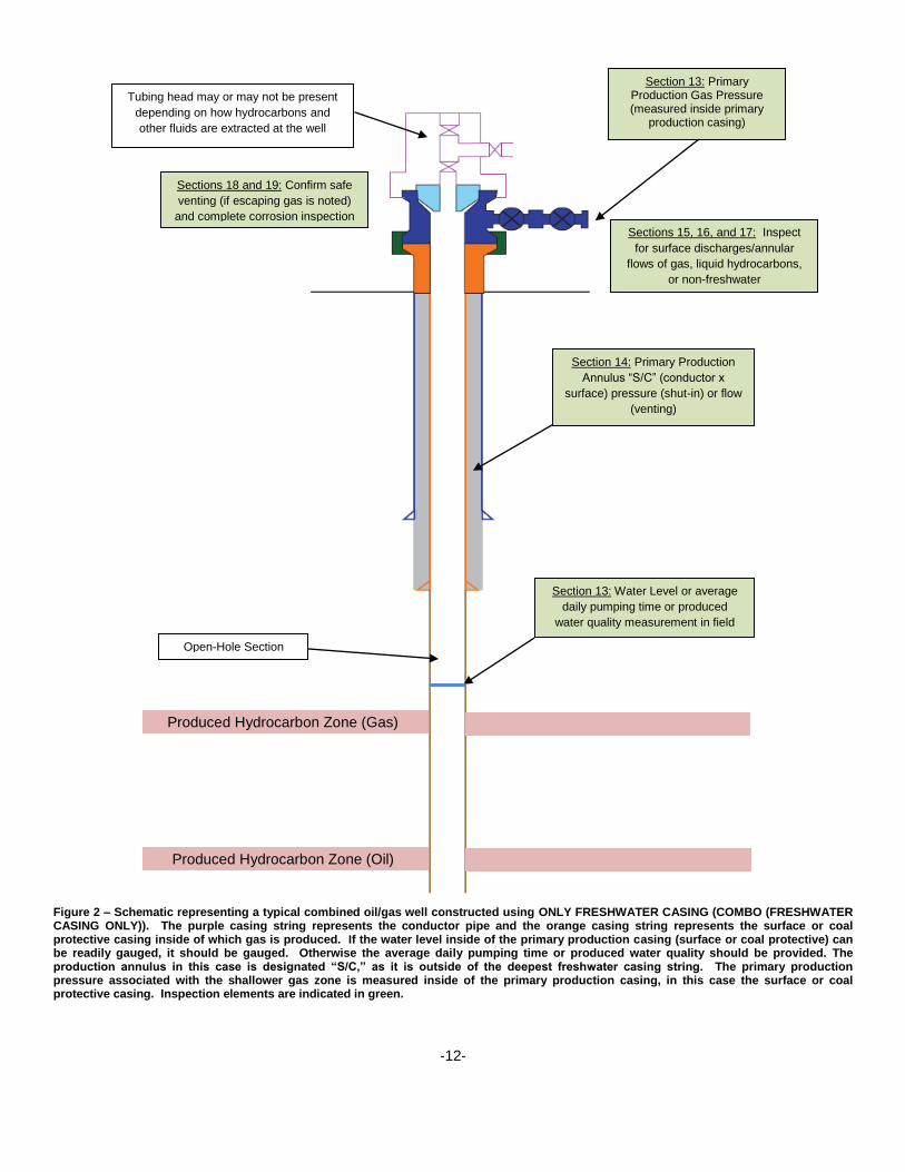
Figure 2 – Schematic representing a typical combined oil/gas well constructed using ONLY FRESHWATER CASING (COMBO (FRESHWATER CASING ONLY)). The purple casing string represents the conductor pipe and the orange casing string represents the surface or coal protective casing inside of which gas is produced. If the water level inside of the primary production casing (surface or coal protective) can be readily gauged, it should be gauged. Otherwise the average daily pumping time or produced water quality should be provided. The production annulus in this case is designated “S/C,” as it is outside of the deepest freshwater casing string. The primary production pressure associated with the shallower gas zone is measured inside of the primary production casing, in this case the surface or coal protective casing. Inspection elements are indicated in green.
Produced Hydrocarbon Zone (Gas)
Produced Hydrocarbon Zone (Oil)
Section 13: Primary Production Gas Pressure (measured inside primary
production casing)
Sections 15, 16, and 17: Inspect
for surface discharges/annular
flows of gas, liquid hydrocarbons,
or non-freshwater
Sections 18 and 19: Confirm safe
venting (if escaping gas is noted)
and complete corrosion inspection
Section 13: Water Level or average
daily pumping time or produced
water quality measurement in field
Section 14: Primary Production
Annulus “S/C” (conductor x
surface) pressure (shut-in) or flow
(venting)
Open-Hole Section
Tubing head may or may not be present
depending on how hydrocarbons and
other fluids are extracted at the well

-13-
Figure 3 – Schematic representing a typical gas well constructed using ONLY FRESHWATER CASING (GAS). The purple casing string represents the conductor pipe and the orange casing string represents the surface or coal protective casing. The primary production pressure associated with the shallower gas zone is measured inside of the primary production casing, in this case the surface or coal protective casing. The production annulus in this case is designated “S/C,” as it is outside of the deepest freshwater casing string. Inspection elements are indicated in green.
Produced Hydrocarbon Zone (Gas)
Section 13: Primary Production Gas Pressure (measured inside primary
production casing)
Section 14: Primary Production
Annulus “S/C” (conductor x
surface) pressure (shut-in) or flow
(venting)
Sections 18 and 19: Confirm safe
venting (if escaping gas is noted)
and complete corrosion inspection
Tubing head may or may not be present
depending on how hydrocarbons and
other fluids are extracted at the well
Open-Hole Section
Sections 15, 16, and 17: Inspect
for surface discharges/annular
flows of gas, liquid hydrocarbons,
or non-freshwater

-14-
Figure 4 – Schematic representing a typical “MULTI-STRING” OPEN-HOLE COMPLETION WITH NO ANNULAR PRODUCTION (OIL OR GAS). The purple casing string represents the conductor pipe, the orange casing string represents the surface or coal protective casing, the green casing string represents the intermediate casing, and the blue casing string represents the production casing. If the well is only equipped with production and surface/coal casing, the “P” annulus is that annulus defined by those two casing strings. The annulus defined by the intermediate casing and surface casing is designated “I.” If multiple intermediate strings are utilized, the deepest is designated “I;” the second deepest, “I1;” and so forth. The annulus defined by the surface casing and conductor pipe is designated “S/C.” If multiple surface or coal protective strings are utilized, the deepest is designated “S/C;” the second deepest, “S/C1;” and so forth. Three different possible cement top positions are indicated as A, B, and C. A and B are for scenarios where the cement is circulated to the surface and inside of the intermediate string but not to the surface, respectively. C is for scenarios where the cement top is left below the intermediate shoe. The production casing may also be set on a packer as indicated to the left in the schematic. Inspection elements for gas wells only are indicated in blue. Those required for both oil and gas wells are indicated in green.
Section 13: Primary Production Gas Pressure (measured inside primary
production casing)
Packer
OR
A
B
C
Surface/Coal Casing
Annulus “S/C” (conductor x
surface or coal)
Intermediate Casing Annulus
“I” (surface or coal x
intermediate)
Production Casing Annulus
“P” (intermediate x
production)
Production Casing Annulus
“P” (intermediate x
production)
Section 14: Primary Production Annulus “P” (intermediate x
production) pressure (shut-in) or flow (venting)
Produced Hydrocarbon Zone (Oil or
Gas)
Sections 15, 16, and 17: Inspect
for surface discharges/annular
flows of gas, liquid hydrocarbons,
or non-freshwater
Sections 18 and 19: Confirm safe
venting (if escaping gas is noted)
and complete corrosion inspection
Open-Hole Sections (if
cement top at position
“C”
Open-Hole Sections
Tubing head may or may not be
present depending on how
hydrocarbons and other fluids are
extracted at the well

-15-
Figure 5 – Schematic representing a typical “MULTI-STRING” OPEN-HOLE COMPLETION WITH ANNULAR PRODUCTION (COMBO if oil and gas produced; GAS if only gas produced). The purple casing string represents the conductor pipe, the orange casing string represents the surface or coal protective casing, the green casing string represents the intermediate casing, and the blue casing string represents the production casing. If the well is only equipped with production and surface/coal casing, the “P” annulus is that annulus defined by those two casing strings and where the annular production gas pressure should be measured. The annulus defined by the intermediate casing and surface casing is designated “I.” If multiple intermediate strings are utilized, the deepest is designated “I;” the second deepest, “I1;” and so forth. The annulus defined by the surface casing and conductor pipe is designated “S/C.” If multiple surface or coal protective strings are utilized, the deepest is designated “S/C;” the second deepest, “S/C1;” and so forth. The production casing may also be set on a packer as indicated to the left in the schematic. Inspection elements for gas wells only are indicated in blue. Those required for combo and gas wells are indicated in green.
Packer
OR
Surface/Coal Casing
Annulus “S/C” (conductor x
surface or coal)
Intermediate Casing Annulus
“I” (surface or coal x
intermediate)
Section 13: Annular Production Gas Pressure (measured outside production casing and inside
intermediate casing)
Produced Hydrocarbon Zone (Oil or Gas)
Produced Hydrocarbon Zone (Gas)
Production Casing Annulus
“P” (intermediate x
production)
Sections 18 and 19: Confirm safe
venting (if escaping gas is noted)
and complete corrosion inspection
Sections 15, 16, and 17: Inspect
for surface discharges/annular
flows of gas, liquid hydrocarbons,
or non-freshwater
Tubing head may or may not be
present depending on how
hydrocarbons and other fluids are
extracted at the well
Section 13: Primary Production Gas Pressure (measured inside primary
production casing)
Open-Hole Sections
Open-Hole Sections
Production Casing Annulus
“P” (intermediate x
production)

-16-
Figure 6 – Schematic representing a typical “MULTI-STRING” CASED-HOLE COMPLETION WITH NO ANNULAR PRODUCTION (OIL OR GAS). The purple casing string represents the conductor pipe, the orange casing string represents the surface or coal protective casing, the green casing string represents the intermediate casing, and the blue casing string represents the production casing. If the well is only equipped with production and surface/coal casing, the “P” annulus is that annulus defined by those two casing strings. The annulus defined by the intermediate casing and surface casing is designated “I.” If multiple intermediate strings are utilized, the deepest is designated “I;” the second deepest, “I1;” and so forth. The annulus defined by the surface casing and conductor pipe is designated “S/C.” If multiple surface or coal protective strings are utilized, the deepest is designated “S/C;” the second deepest, “S/C1;” and so forth. Three different cement top positions are indicated as A, B, and C. A and B are for scenarios where the cement is circulated to the surface and inside of the intermediate string but not to surface, respectively. C is for scenarios where the cement top is left below the intermediate shoe. Inspection elements for gas wells only are indicated in blue. Those required for both oil and gas wells are indicated in green.
A
B
C
Surface/Coal Casing
Annulus “S/C” (conductor x
surface or coal)
Intermediate Casing Annulus
“I” (surface or coal x
intermediate)
Production Casing Annulus
“P” (intermediate x
production)
Produced Hydrocarbon Zone (Oil or
Gas)
Section 13: Primary Production Gas Pressure (measured inside primary
production casing)
Section 14: Primary Production Annulus “P” (intermediate x
production) pressure (shut-in) or flow (venting)
Sections 18 and 19: Confirm safe
venting (if escaping gas is noted)
and complete corrosion inspection
Sections 15, 16, and 17: Inspect
for surface discharges/annular
flows of gas, liquid hydrocarbons,
or non-freshwater
Open-Hole Section (if cement
top at position “C”
Tubing head may or may not be
present depending on how
hydrocarbons and other fluids are
extracted at the well

-17-
Figure 7 – Schematic representing a typical “MULTI-STRING” CASED-HOLE COMPLETION WITH ANNULAR PRODUCTION (COMBO if oil and gas produced; GAS if only gas produced). The purple casing string represents the conductor pipe, the orange casing string represents the surface or coal protective casing, the green casing string represents the intermediate casing, and the blue casing string represents the production casing. If the well is only equipped with production and surface/coal casing, the “P” annulus is that annulus defined by those two casing strings and represents where the annular production gas pressure should be measured. The annulus defined by the intermediate casing and surface casing is designated “I.” If multiple intermediate strings are utilized, the deepest is designated “I;” the second deepest, “I1;” and so forth. The annulus defined by the surface casing and conductor pipe is designated “S/C.” If multiple surface or coal protective strings are utilized, the deepest is designated “S/C;” the second deepest, “S/C1;” and so forth. Inspection elements for gas wells only are indicated in blue. Those required for combo and gas wells are indicated in green.
Surface/Coal Casing
Annulus “S/C” (conductor x
surface or coal)
Intermediate Casing Annulus
“I” (surface or coal x
intermediate)
Produced Hydrocarbon Zone (Oil or Gas)
Produced Hydrocarbon Zone (Gas)
Production Casing Annulus
“P” (intermediate x
production)
Section 13: Annular Production Gas Pressure (measured outside production casing and inside
intermediate casing)
Tubing head may or may not be
present depending on how
hydrocarbons and other fluids are
extracted at the well
Sections 18 and 19: Confirm safe
venting (if escaping gas is noted)
and complete corrosion inspection
Sections 15, 16, and 17: Inspect
for surface discharges/annular
flows of gas, liquid hydrocarbons,
or non-freshwater
Open-Hole Section
Section 13: Primary Production Gas Pressure (measured inside primary
production casing)

-18-
Figure 8 – Hydrogen sulfide and % LEL screening procedure for wells with and without cellars. This diagram DOES NOT indicate the procedure used to identify whether or not leaks or annular vent flows consist of combustible gas, but rather represents a screening procedure for verifying the wellhead environment is safe when combustible gas leaks or annular vent flows are known to exist.
360o
3 ft
Well Cellar No Cellar
3 ft 3 ft