Instructions for assembly: Steering and pushing aid ... · Instructions for assembly: Steering and...
24
Sorg Rollstuhltechnik [July 14] Instructions for assembly: Steering and pushing aid (Outdoor Front End)
Transcript of Instructions for assembly: Steering and pushing aid ... · Instructions for assembly: Steering and...
Sorg Rollstuhltechnik
[July 14]
Instructions for assembly: Steering and pushing aid (Outdoor Front End)
Instructions for assembly: Steering and pushing aid (Outdoor Front End)
Page 2 of 22
TELESCOPIC STEERING AND PUSHING AID FOR ALL MODELS (EXCEPT FOR MIO & KIKA) .................................................. 2
1. Assembly ................................................................................................................................................................................ 3 1.1 Adapter ................................................................................................................................................................................ 3 1.2 Jack up aid .......................................................................................................................................................................... 4 1.3.1 Outdoor Front End (width adjustment) ......................................................................................................................... 4 1.3.2 Outdoor Front End (length adjustment) ....................................................................................................................... 5 1.4 Outdoor Front End (height adjustment) .......................................................................................................................... 5 1.5 Splash guard (optional) ..................................................................................................................................................... 6 2. Operation ............................................................................................................................................................................... 6 3. Overall view models / table of sizes ................................................................................................................................... 8 4. Spare part list ........................................................................................................................................................................ 9
STEERING AND PUSHING AID FOR WHEELCHAIR MODEL MIO ............................................................................................. 11
1. Assembly ............................................................................................................................................................................. 11 1.1 Stiffener plate at the front frame cross bar .................................................................................................................. 11 1.2 Stiffener plate at the rear frame cross bar ................................................................................................................... 12 1.2.1 With long lower leg lengths (from approx. 15cm) .................................................................................................... 12 1.2.2 With short lower leg lengths (up to approx. 15cm) ................................................................................................. 12 1.3 Jack up aid ....................................................................................................................................................................... 13 1.4 Assembly of the front end part ...................................................................................................................................... 13 1.5 Height adjustment of the steering and pushing aid .................................................................................................... 14 2. Spare part list Mio ............................................................................................................................................................. 15
STEERING AND PUSHING AID FOR WHEELCHAIR MODEL KIKA ............................................................................................ 17
1. Assembly ............................................................................................................................................................................. 17 1.1 Assembly of the front end part (width adjustment) ..................................................................................................... 17 1.2 Adapter ............................................................................................................................................................................. 19 1.3 Jack up aid ....................................................................................................................................................................... 19 1.4 Insert the front end part .................................................................................................................................................. 20 2. Spare part list Kika ............................................................................................................................................................ 21
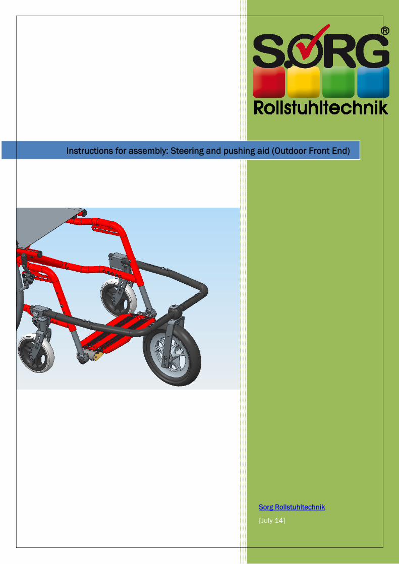
Telescopic steering and pushing aid for all models (except for Mio & Kika)
Instructions for assembly: Steering and pushing aid (Outdoor Front End)
Page 3 of 22
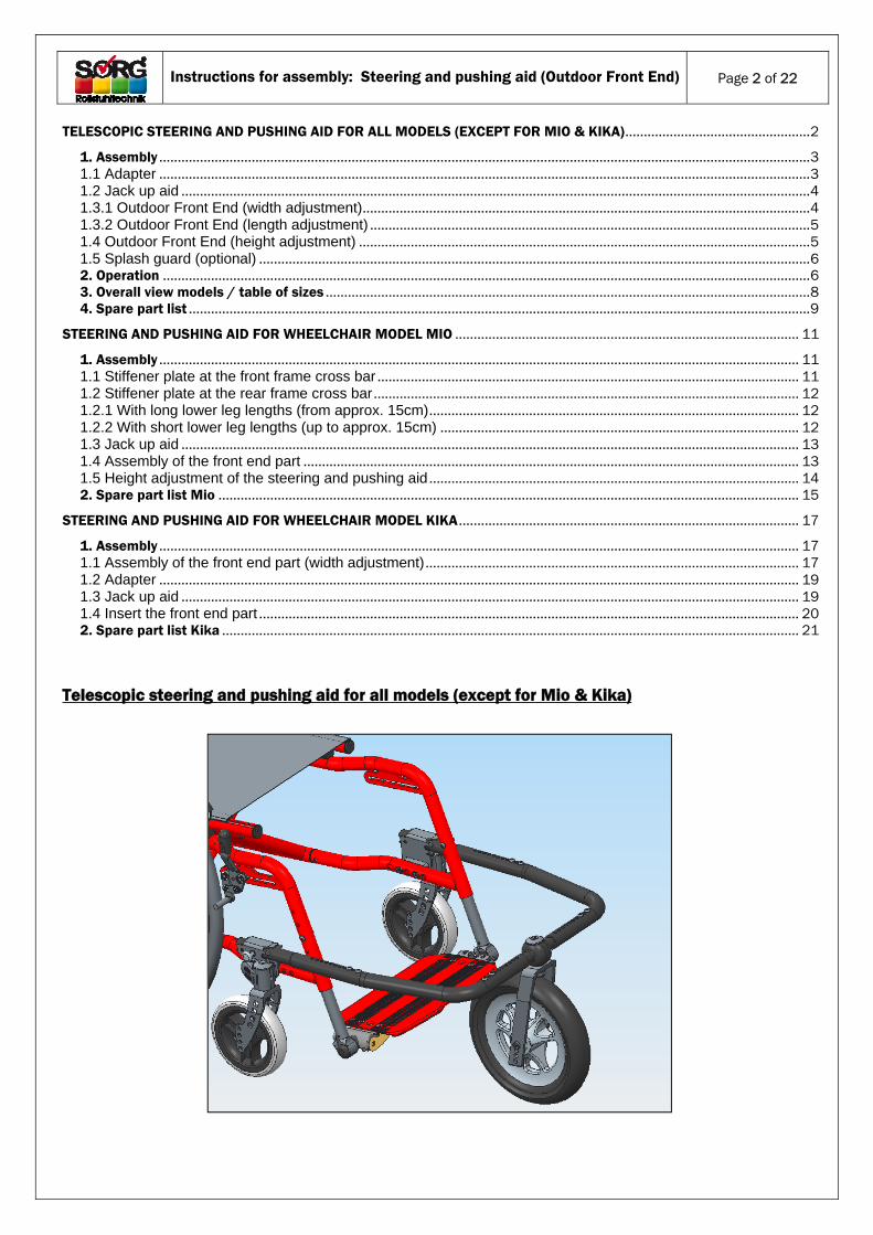
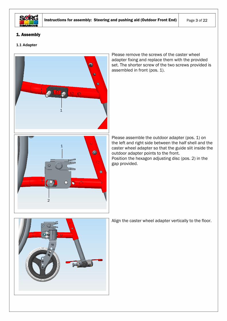
1. Assembly
1.1 Adapter
Please remove the screws of the caster wheel adapter fixing and replace them with the provided set. The shorter screw of the two screws provided is assembled in front (pos. 1).
Please assemble the outdoor adapter (pos. 1) on the left and right side between the half shell and the caster wheel adapter so that the guide slit inside the outdoor adapter points to the front. Position the hexagon adjusting disc (pos. 2) in the gap provided. Align the caster wheel adapter vertically to the floor.
1
2
1
Instructions for assembly: Steering and pushing aid (Outdoor Front End)
Page 4 of 22
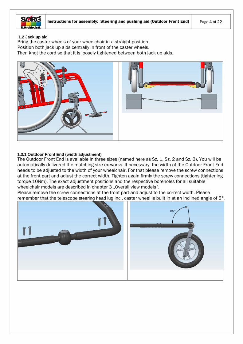
1.2 Jack up aid Bring the caster wheels of your wheelchair in a straight position. Position both jack up aids centrally in front of the caster wheels. Then knot the cord so that it is loosely tightened between both jack up aids.
1.3.1 Outdoor Front End (width adjustment) The Outdoor Front End is available in three sizes (named here as Sz. 1, Sz. 2 and Sz. 3). You will be automatically delivered the matching size ex works. If necessary, the width of the Outdoor Front End needs to be adjusted to the width of your wheelchair. For that please remove the screw connections at the front part and adjust the correct width. Tighten again firmly the screw connections (tightening torque 10Nm). The exact adjustment positions and the respective boreholes for all suitable wheelchair models are described in chapter 3 „Overall view models“. Please remove the screw connections at the front part and adjust to the correct width. Please remember that the telescope steering head lug incl. caster wheel is built in at an inclined angle of 5°.
85°
Instructions for assembly: Steering and pushing aid (Outdoor Front End)
Page 5 of 22
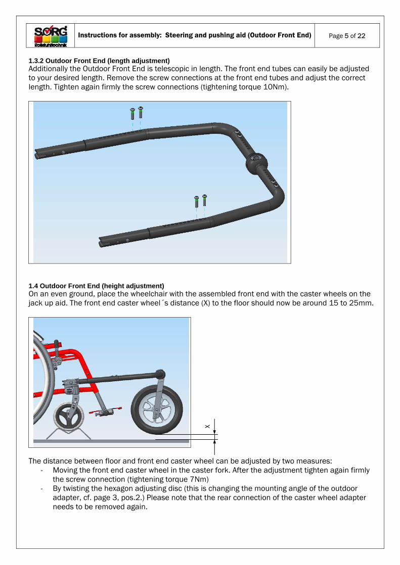
1.3.2 Outdoor Front End (length adjustment) Additionally the Outdoor Front End is telescopic in length. The front end tubes can easily be adjusted to your desired length. Remove the screw connections at the front end tubes and adjust the correct length. Tighten again firmly the screw connections (tightening torque 10Nm).
1.4 Outdoor Front End (height adjustment) On an even ground, place the wheelchair with the assembled front end with the caster wheels on the jack up aid. The front end caster wheel´s distance (X) to the floor should now be around 15 to 25mm.
The distance between floor and front end caster wheel can be adjusted by two measures:
- Moving the front end caster wheel in the caster fork. After the adjustment tighten again firmly the screw connection (tightening torque 7Nm)
- By twisting the hexagon adjusting disc (this is changing the mounting angle of the outdoor adapter, cf. page 3, pos.2.) Please note that the rear connection of the caster wheel adapter needs to be removed again.
X
Instructions for assembly: Steering and pushing aid (Outdoor Front End)
Page 6 of 22
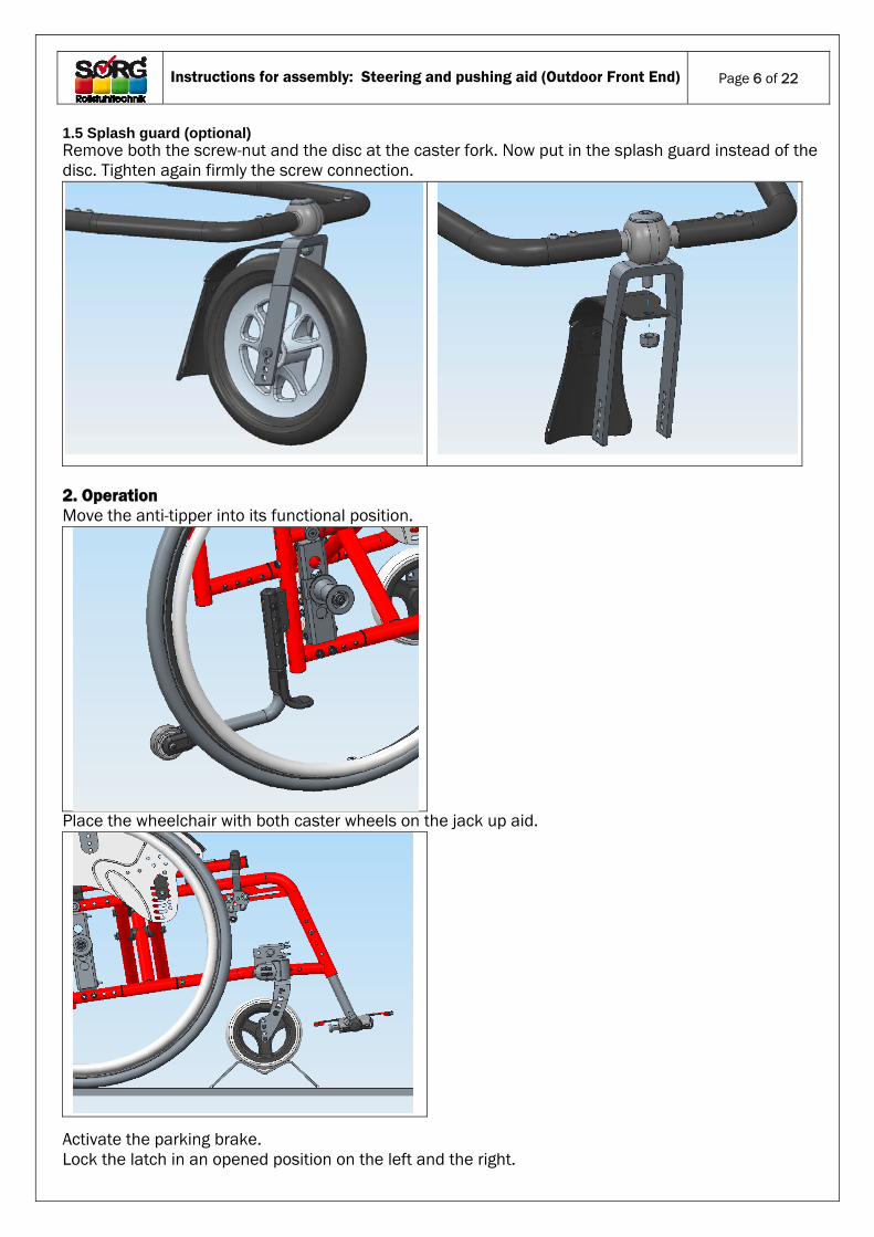
1.5 Splash guard (optional) Remove both the screw-nut and the disc at the caster fork. Now put in the splash guard instead of the disc. Tighten again firmly the screw connection.
2. Operation Move the anti-tipper into its functional position.
Place the wheelchair with both caster wheels on the jack up aid.
Activate the parking brake. Lock the latch in an opened position on the left and the right.
Instructions for assembly: Steering and pushing aid (Outdoor Front End)
Page 7 of 22
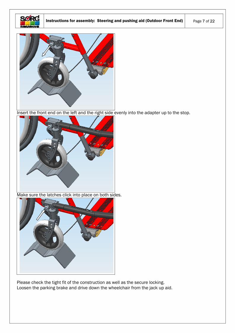
Insert the front end on the left and the right side evenly into the adapter up to the stop.
Make sure the latches click into place on both sides.
Please check the tight fit of the construction as well as the secure locking. Loosen the parking brake and drive down the wheelchair from the jack up aid.
Instructions for assembly: Steering and pushing aid (Outdoor Front End)
Page 8 of 22
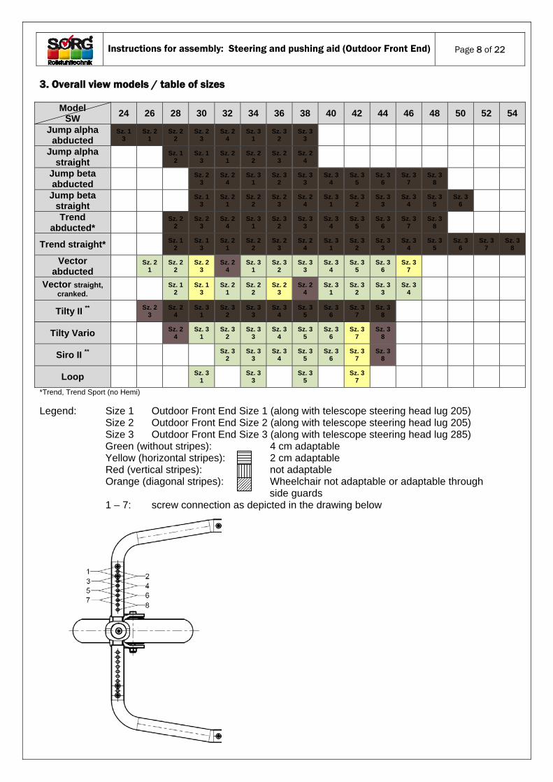
3. Overall view models / table of sizes
Model SW
24 26 28 30 32 34 36 38 40 42 44 46 48 50 52 54
Jump alpha abducted
Sz. 1 3
Sz. 2 1
Sz. 2 2
Sz. 2 3
Sz. 2 4
Sz. 3 1
Sz. 3 2
Sz. 3 3
Jump alpha straight
Sz. 1
2 Sz. 1
3 Sz. 2
1 Sz. 2
2 Sz. 2
3 Sz. 2
4
Jump beta abducted
Sz. 2
3 Sz. 2
4 Sz. 3
1 Sz. 3
2 Sz. 3
3 Sz. 3
4 Sz. 3
5 Sz. 3
6 Sz. 3
7 Sz. 3
8
Jump beta straight
Sz. 1
3 Sz. 2
1 Sz. 2
2 Sz. 2
3 Sz. 2
4 Sz. 3
1 Sz. 3
2 Sz. 3
3 Sz. 3
4 Sz. 3
5 Sz. 3
6
Trend abducted*
Sz. 2 2
Sz. 2 3
Sz. 2 4
Sz. 3 1
Sz. 3 2
Sz. 3 3
Sz. 3 4
Sz. 3 5
Sz. 3 6
Sz. 3 7
Sz. 3 8
Trend straight* Sz. 1
2 Sz. 1
3 Sz. 2
1 Sz. 2
2 Sz. 2
3 Sz. 2
4 Sz. 3
1 Sz. 3
2 Sz. 3
3 Sz. 3
4 Sz. 3
5 Sz. 3
6 Sz. 3
7 Sz. 3
8
Vector abducted
Sz. 2
1 Sz. 2
2 Sz. 2
3 Sz. 2
4 Sz. 3
1 Sz. 3
2 Sz. 3
3 Sz. 3
4 Sz. 3
5 Sz. 3
6 Sz. 3
7
Vector straight, cranked.
Sz. 1
2 Sz. 1
3 Sz. 2
1 Sz. 2
2 Sz. 2
3 Sz. 2
4 Sz. 3
1 Sz. 3
2 Sz. 3
3 Sz. 3
4
Tilty II ** Sz. 2
3 Sz. 2
4 Sz. 3
1 Sz. 3
2 Sz. 3
3 Sz. 3
4 Sz. 3
5 Sz. 3
6 Sz. 3
7 Sz. 3
8
Tilty Vario Sz. 2
4 Sz. 3
1 Sz. 3
2 Sz. 3
3 Sz. 3
4 Sz. 3
5 Sz. 3
6 Sz. 3
7 Sz. 3
8
Siro II ** Sz. 3
2 Sz. 3
3 Sz. 3
4 Sz. 3
5 Sz. 3
6 Sz. 3
7 Sz. 3
8
Loop Sz. 3
1
Sz. 3 3
Sz. 3
5
Sz. 3 7
*Trend, Trend Sport (no Hemi)
Legend: Size 1 Outdoor Front End Size 1 (along with telescope steering head lug 205) Size 2 Outdoor Front End Size 2 (along with telescope steering head lug 205) Size 3 Outdoor Front End Size 3 (along with telescope steering head lug 285) Green (without stripes): 4 cm adaptable Yellow (horizontal stripes): 2 cm adaptable Red (vertical stripes): not adaptable
Orange (diagonal stripes): Wheelchair not adaptable or adaptable through side guards
1 – 7: screw connection as depicted in the drawing below
Instructions for assembly: Steering and pushing aid (Outdoor Front End)
Page 9 of 22
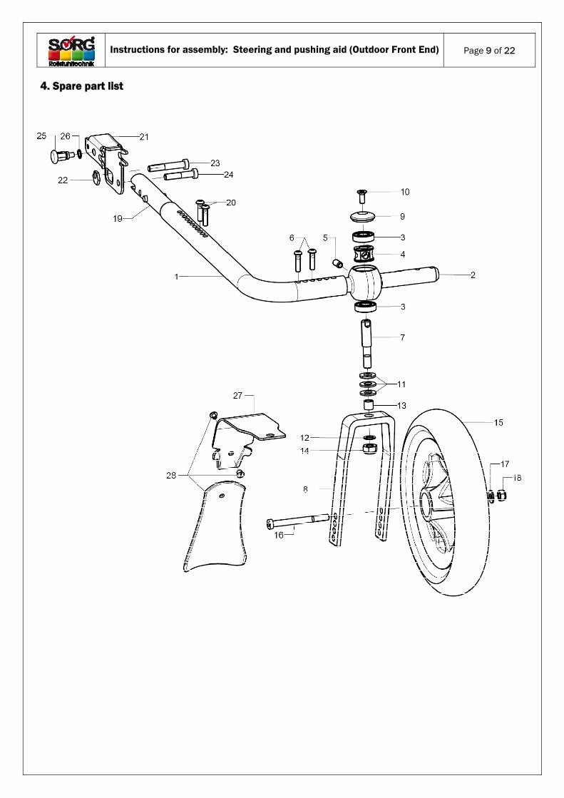
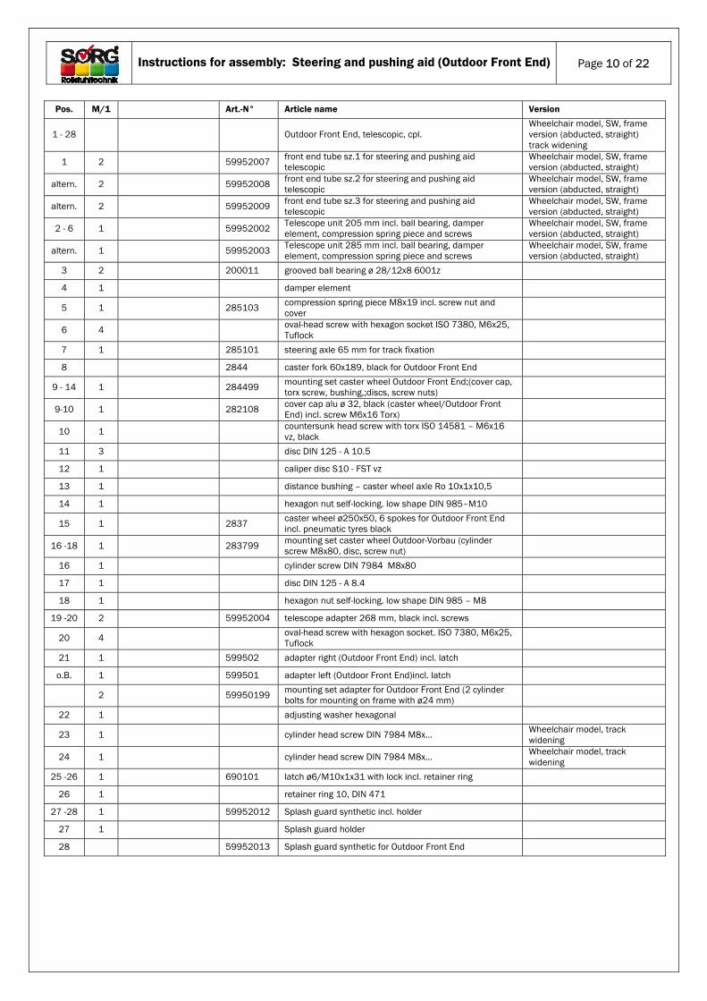
4. Spare part list
Instructions for assembly: Steering and pushing aid (Outdoor Front End)
Page 10 of 22
Pos. M/1 Art.-N° Article name Version
1 - 28 Outdoor Front End, telescopic, cpl. Wheelchair model, SW, frame version (abducted, straight) track widening
1 2 59952007 front end tube sz.1 for steering and pushing aid telescopic
Wheelchair model, SW, frame version (abducted, straight)
altern. 2 59952008 front end tube sz.2 for steering and pushing aid telescopic
Wheelchair model, SW, frame version (abducted, straight)
altern. 2 59952009 front end tube sz.3 for steering and pushing aid telescopic
Wheelchair model, SW, frame version (abducted, straight)
2 - 6 1 59952002 Telescope unit 205 mm incl. ball bearing, damper element, compression spring piece and screws
Wheelchair model, SW, frame version (abducted, straight)
altern. 1 59952003 Telescope unit 285 mm incl. ball bearing, damper element, compression spring piece and screws
Wheelchair model, SW, frame version (abducted, straight)
3 2 200011 grooved ball bearing ø 28/12x8 6001z
4 1 damper element
5 1 285103 compression spring piece M8x19 incl. screw nut and cover
6 4 oval-head screw with hexagon socket ISO 7380, M6x25, Tuflock
7 1 285101 steering axle 65 mm for track fixation
8 2844 caster fork 60x189, black for Outdoor Front End
9 - 14 1 284499 mounting set caster wheel Outdoor Front End;(cover cap, torx screw, bushing,;discs, screw nuts)
9-10 1 282108 cover cap alu ø 32, black (caster wheel/Outdoor Front End) incl. screw M6x16 Torx)
10 1 countersunk head screw with torx ISO 14581 – M6x16 vz, black
11 3 disc DIN 125 - A 10.5
12 1 caliper disc S10 - FST vz
13 1 distance bushing – caster wheel axle Ro 10x1x10,5
14 1 hexagon nut self-locking. low shape DIN 985–M10
15 1 2837 caster wheel ø250x50, 6 spokes for Outdoor Front End incl. pneumatic tyres black
16 -18 1 283799 mounting set caster wheel Outdoor-Vorbau (cylinder screw M8x80, disc, screw nut)
16 1 cylinder screw DIN 7984 M8x80
17 1 disc DIN 125 - A 8.4
18 1 hexagon nut self-locking. low shape DIN 985 – M8
19 -20 2 59952004 telescope adapter 268 mm, black incl. screws
20 4 oval-head screw with hexagon socket. ISO 7380, M6x25, Tuflock
21 1 599502 adapter right (Outdoor Front End) incl. latch
o.B. 1 599501 adapter left (Outdoor Front End)incl. latch
2 59950199 mounting set adapter for Outdoor Front End (2 cylinder bolts for mounting on frame with ø24 mm)
22 1 adjusting washer hexagonal
23 1 cylinder head screw DIN 7984 M8x… Wheelchair model, track widening
24 1 cylinder head screw DIN 7984 M8x… Wheelchair model, track widening
25 -26 1 690101 latch ø6/M10x1x31 with lock incl. retainer ring
26 1 retainer ring 10, DIN 471
27 -28 1 59952012 Splash guard synthetic incl. holder
27 1 Splash guard holder
28 59952013 Splash guard synthetic for Outdoor Front End
Instructions for assembly: Steering and pushing aid (Outdoor Front End)
Page 11 of 22
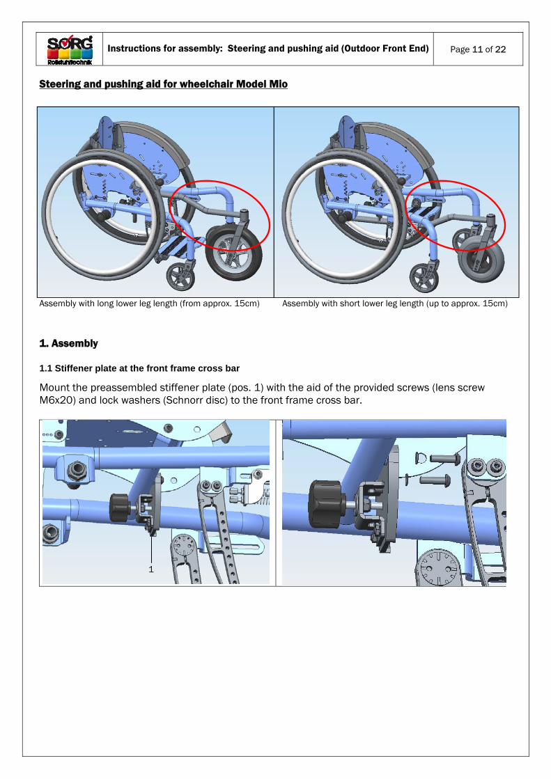
Steering and pushing aid for wheelchair Model Mio
Assembly with long lower leg length (from approx. 15cm) Assembly with short lower leg length (up to approx. 15cm) 1. Assembly
1.1 Stiffener plate at the front frame cross bar
Mount the preassembled stiffener plate (pos. 1) with the aid of the provided screws (lens screw M6x20) and lock washers (Schnorr disc) to the front frame cross bar.
1
Instructions for assembly: Steering and pushing aid (Outdoor Front End)
Page 12 of 22
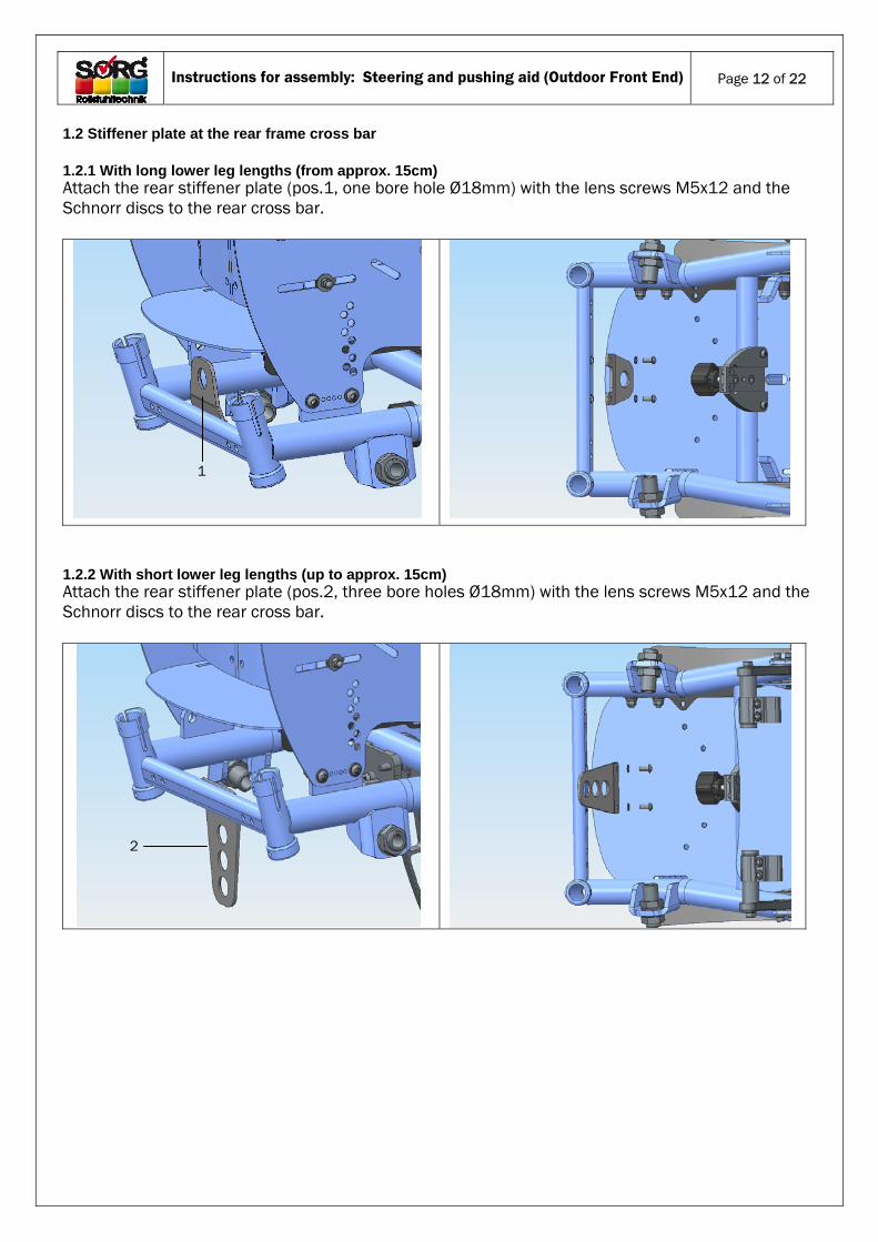
1.2 Stiffener plate at the rear frame cross bar 1.2.1 With long lower leg lengths (from approx. 15cm) Attach the rear stiffener plate (pos.1, one bore hole Ø18mm) with the lens screws M5x12 and the Schnorr discs to the rear cross bar.
1.2.2 With short lower leg lengths (up to approx. 15cm) Attach the rear stiffener plate (pos.2, three bore holes Ø18mm) with the lens screws M5x12 and the Schnorr discs to the rear cross bar.
1
2
Instructions for assembly: Steering and pushing aid (Outdoor Front End)
Page 13 of 22
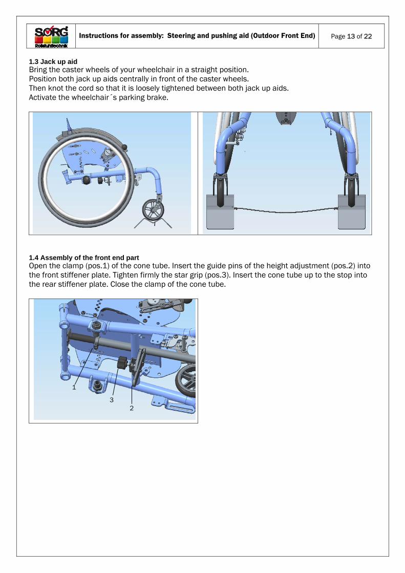
1.3 Jack up aid Bring the caster wheels of your wheelchair in a straight position. Position both jack up aids centrally in front of the caster wheels. Then knot the cord so that it is loosely tightened between both jack up aids. Activate the wheelchair´s parking brake.
1.4 Assembly of the front end part Open the clamp (pos.1) of the cone tube. Insert the guide pins of the height adjustment (pos.2) into the front stiffener plate. Tighten firmly the star grip (pos.3). Insert the cone tube up to the stop into the rear stiffener plate. Close the clamp of the cone tube.
2
1
3
Instructions for assembly: Steering and pushing aid (Outdoor Front End)
Page 14 of 22
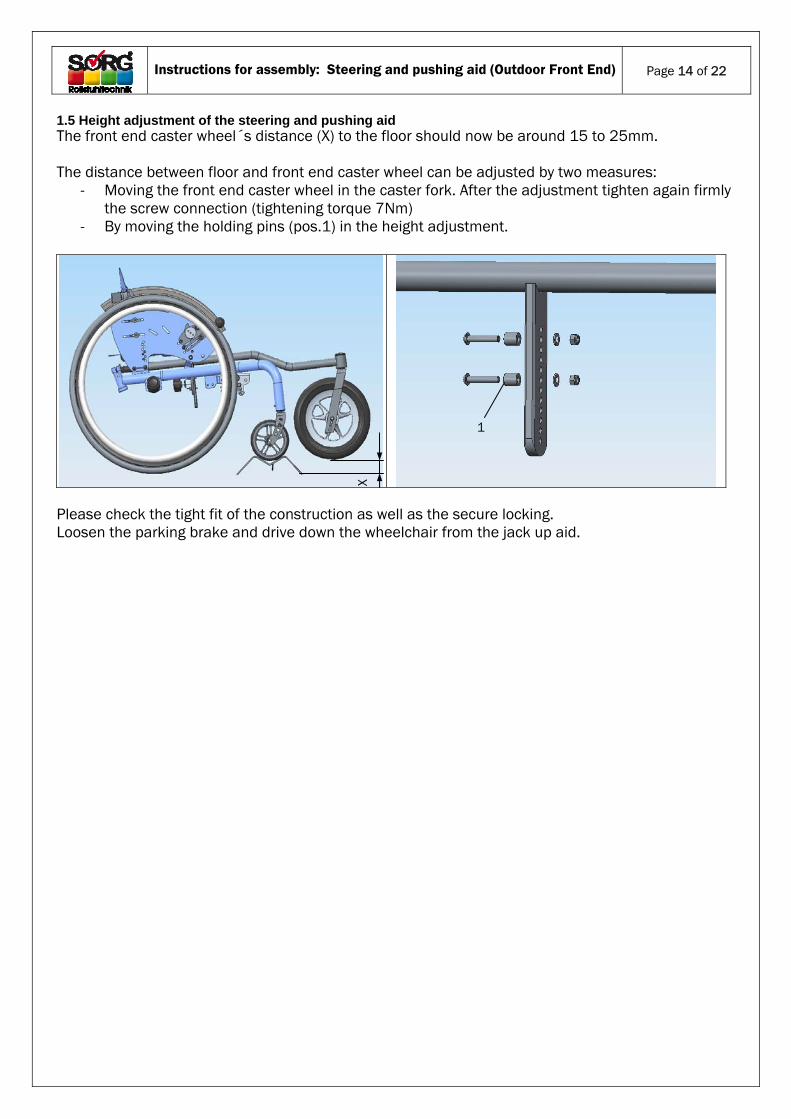
1.5 Height adjustment of the steering and pushing aid The front end caster wheel´s distance (X) to the floor should now be around 15 to 25mm. The distance between floor and front end caster wheel can be adjusted by two measures:
- Moving the front end caster wheel in the caster fork. After the adjustment tighten again firmly the screw connection (tightening torque 7Nm)
- By moving the holding pins (pos.1) in the height adjustment.
Please check the tight fit of the construction as well as the secure locking. Loosen the parking brake and drive down the wheelchair from the jack up aid.
X
1
Instructions for assembly: Steering and pushing aid (Outdoor Front End)
Page 15 of 22
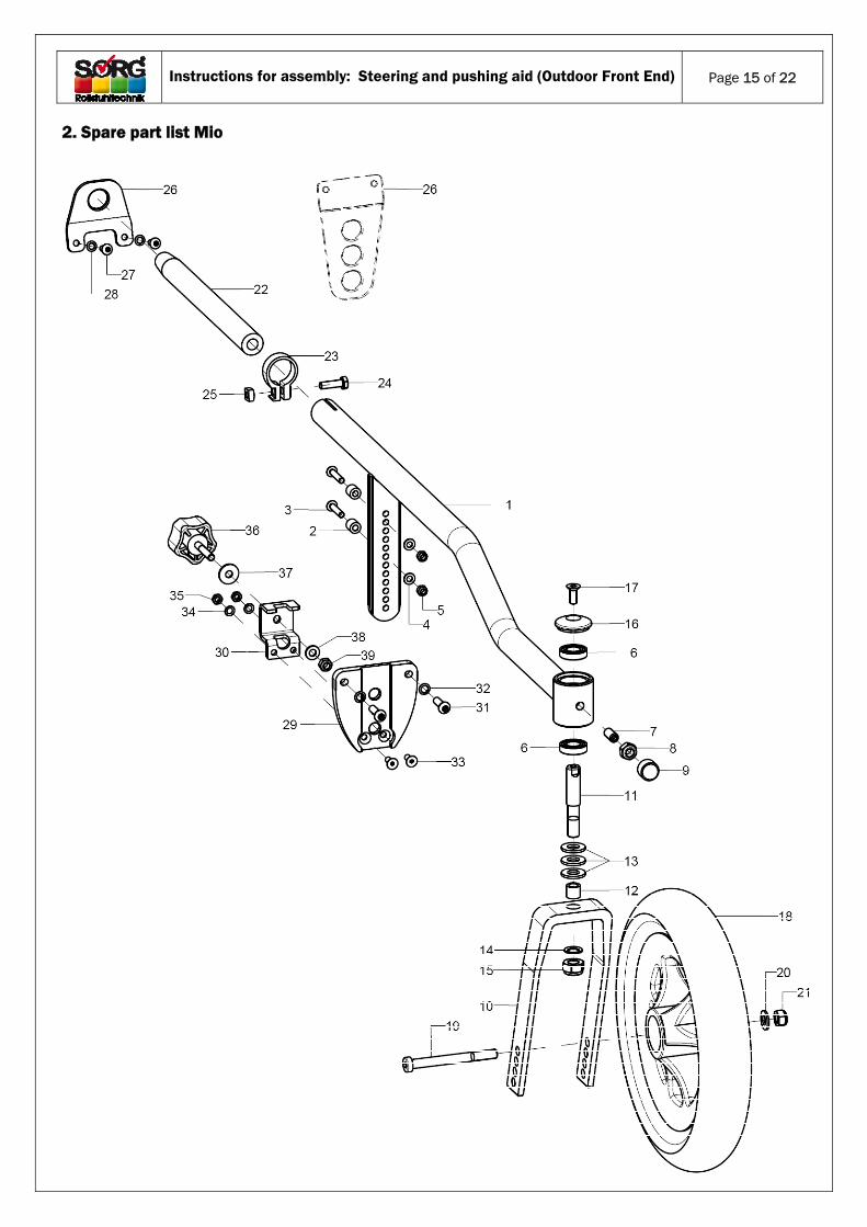
2. Spare part list Mio
Instructions for assembly: Steering and pushing aid (Outdoor Front End)
Page 16 of 22
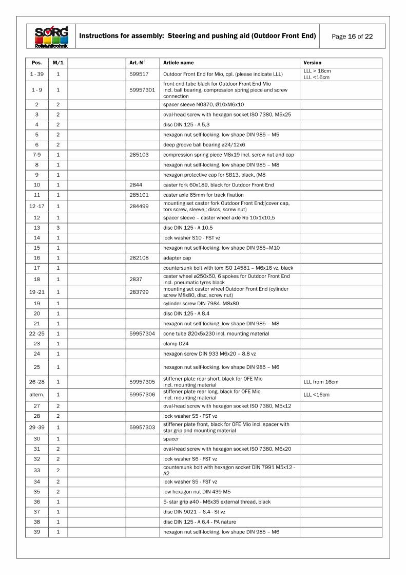
Pos. M/1 Art.-N° Article name Version
1 - 39 1 599517 Outdoor Front End for Mio, cpl. (please indicate LLL) LLL > 16cm LLL <16cm
1 - 9 1 59957301 front end tube black for Outdoor Front End Mio incl. ball bearing, compression spring piece and screw connection
2 2 spacer sleeve N0370, Ø10xM6x10
3 2 oval-head screw with hexagon socket ISO 7380, M5x25
4 2 disc DIN 125 - A 5,3
5 2 hexagon nut self-locking. low shape DIN 985 – M5
6 2 deep groove ball bearing ø24/12x6
7-9 1 285103 compression spring piece M8x19 incl. screw nut and cap
8 1 hexagon nut self-locking. low shape DIN 985 – M8
9 1 hexagon protective cap for SB13, black, (M8
10 1 2844 caster fork 60x189, black for Outdoor Front End
11 1 285101 caster axle 65mm for track fixation
12 -17 1 284499 mounting set caster fork Outdoor Front End;(cover cap, torx screw, sleeve,; discs, screw nut)
12 1 spacer sleeve – caster wheel axle Ro 10x1x10,5
13 3 disc DIN 125 - A 10,5
14 1 lock washer S10 - FST vz
15 1 hexagon nut self-locking. low shape DIN 985–M10
16 1 282108 adapter cap
17 1 countersunk bolt with torx ISO 14581 – M6x16 vz, black
18 1 2837 caster wheel ø250x50, 6 spokes for Outdoor Front End incl. pneumatic tyres black
19 -21 1 283799 mounting set caster wheel Outdoor Front End (cylinder screw M8x80, disc, screw nut)
19 1 cylinder screw DIN 7984 M8x80
20 1 disc DIN 125 - A 8.4
21 1 hexagon nut self-locking. low shape DIN 985 – M8
22 -25 1 59957304 cone tube Ø20x5x230 incl. mounting material
23 1 clamp D24
24 1 hexagon screw DIN 933 M6x20 – 8.8 vz
25 1 hexagon nut self-locking. low shape DIN 985 – M6
26 -28 1 59957305 stiffener plate rear short, black for OFE Mio incl. mounting material LLL from 16cm
altern. 1 59957306 stiffener plate rear long, black for OFE Mio incl. mounting material LLL <16cm
27 2 oval-head screw with hexagon socket ISO 7380, M5x12
28 2 lock washer S5 - FST vz
29 -39 1 59957303 stiffener plate front, black for OFE Mio incl. spacer with star grip and mounting material
30 1 spacer
31 2 oval-head screw with hexagon socket ISO 7380, M6x20
32 2 lock washer S6 - FST vz
33 2 countersunk bolt with hexagon socket DIN 7991 M5x12 - A2
34 2 lock washer S5 - FST vz
35 2 low hexagon nut DIN 439 M5
36 1 5- star grip ø40 - M6x35 external thread, black
37 1 disc DIN 9021 – 6.4 - St vz
38 1 disc DIN 125 - A 6.4 - PA nature
39 1 hexagon nut self-locking. low shape DIN 985 – M6
Instructions for assembly: Steering and pushing aid (Outdoor Front End)
Page 17 of 22
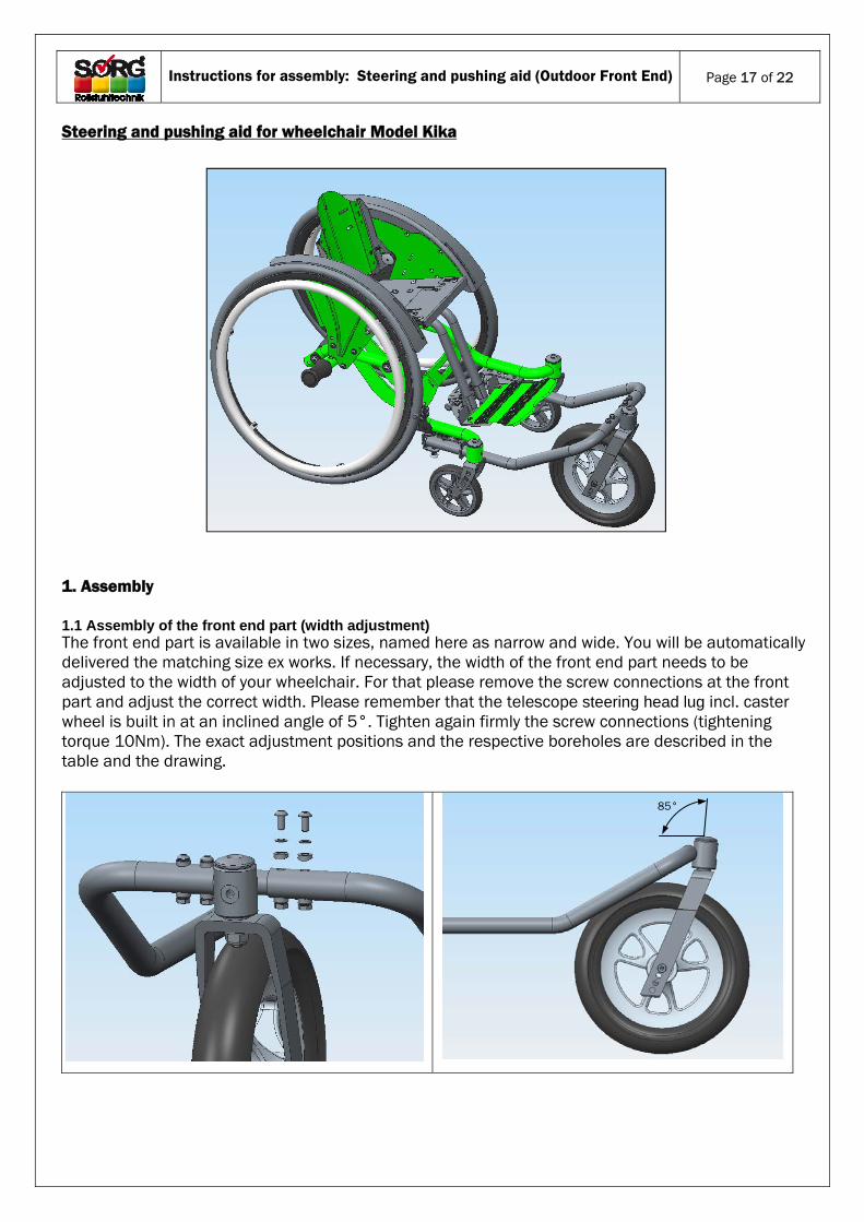
Steering and pushing aid for wheelchair Model Kika 1. Assembly
1.1 Assembly of the front end part (width adjustment) The front end part is available in two sizes, named here as narrow and wide. You will be automatically delivered the matching size ex works. If necessary, the width of the front end part needs to be adjusted to the width of your wheelchair. For that please remove the screw connections at the front part and adjust the correct width. Please remember that the telescope steering head lug incl. caster wheel is built in at an inclined angle of 5°. Tighten again firmly the screw connections (tightening torque 10Nm). The exact adjustment positions and the respective boreholes are described in the table and the drawing.
85°
Instructions for assembly: Steering and pushing aid (Outdoor Front End)
Page 18 of 22
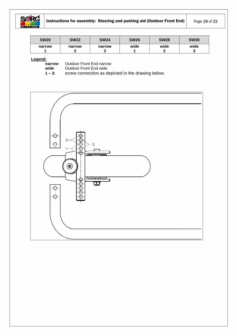
Legend: narrow Outdoor Front End narrow
wide Outdoor Front End wide 1 – 3: screw connection as depicted in the drawing below.
SW20 SW22 SW24 SW26 SW28 SW30
narrow 1
narrow 2
narrow 3
wide 1
wide 2
wide 3
Instructions for assembly: Steering and pushing aid (Outdoor Front End)
Page 19 of 22
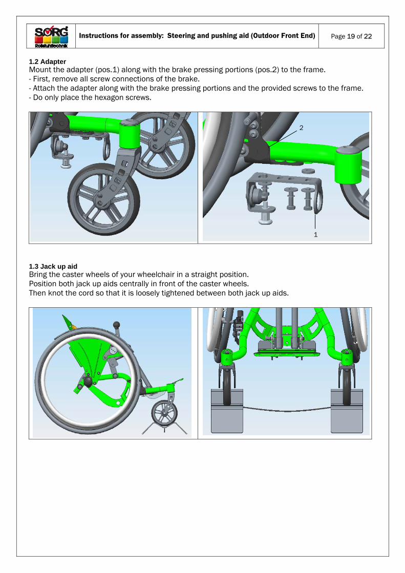
1.2 Adapter Mount the adapter (pos.1) along with the brake pressing portions (pos.2) to the frame. - First, remove all screw connections of the brake. - Attach the adapter along with the brake pressing portions and the provided screws to the frame. - Do only place the hexagon screws.
1.3 Jack up aid Bring the caster wheels of your wheelchair in a straight position. Position both jack up aids centrally in front of the caster wheels. Then knot the cord so that it is loosely tightened between both jack up aids.
1
2
Instructions for assembly: Steering and pushing aid (Outdoor Front End)
Page 20 of 22
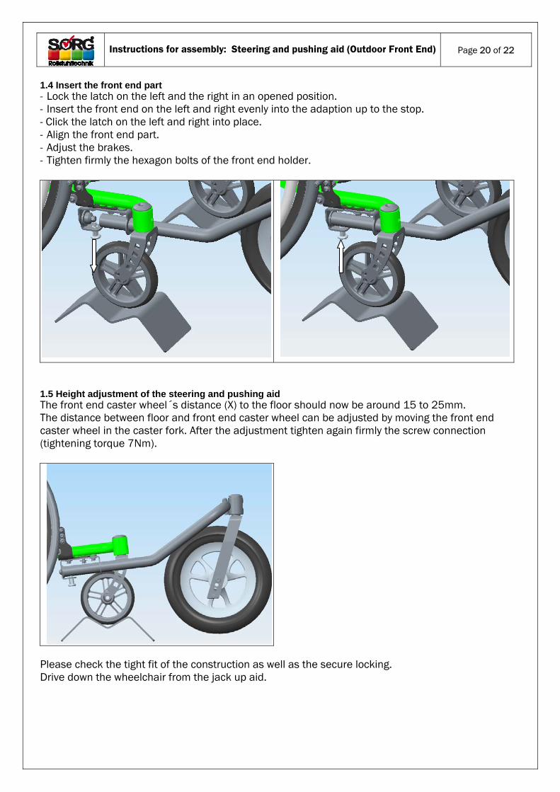
1.4 Insert the front end part - Lock the latch on the left and the right in an opened position. - Insert the front end on the left and right evenly into the adaption up to the stop. - Click the latch on the left and right into place. - Align the front end part. - Adjust the brakes. - Tighten firmly the hexagon bolts of the front end holder.
1.5 Height adjustment of the steering and pushing aid The front end caster wheel´s distance (X) to the floor should now be around 15 to 25mm. The distance between floor and front end caster wheel can be adjusted by moving the front end caster wheel in the caster fork. After the adjustment tighten again firmly the screw connection (tightening torque 7Nm).
Please check the tight fit of the construction as well as the secure locking. Drive down the wheelchair from the jack up aid.
Instructions for assembly: Steering and pushing aid (Outdoor Front End)
Page 21 of 22
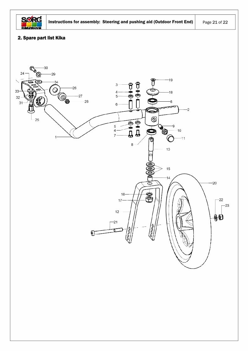
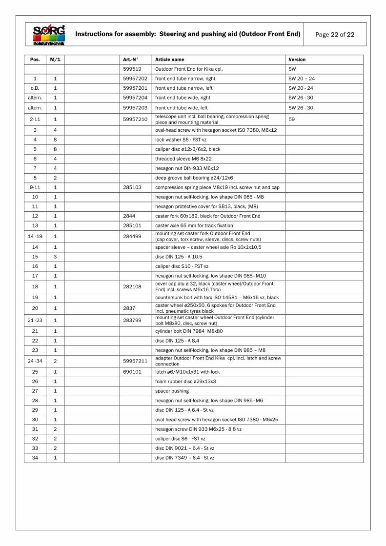
2. Spare part list Kika
Instructions for assembly: Steering and pushing aid (Outdoor Front End)
Page 22 of 22
Pos. M/1 Art.-N° Article name Version
599519 Outdoor Front End for Kika cpl. SW
1 1 59957202 front end tube narrow, right SW 20 – 24
o.B. 1 59957201 front end tube narrow, left SW 20 - 24
altern. 1 59957204 front end tube wide, right SW 26 - 30
altern. 1 59957203 front end tube wide, left SW 26 - 30
2-11 1 59957210 telescope unit incl. ball bearing, compression spring piece and mounting material 59
3 4 oval-head screw with hexagon socket ISO 7380, M6x12
4 8 lock washer S6 - FST vz
5 8 caliper disc ø12x3/6x2, black
6 4 threaded sleeve M6 8x22
7 4 hexagon nut DIN 933 M6x12
8 2 deep groove ball bearing ø24/12x6
9-11 1 285103 compression spring piece M8x19 incl. screw nut and cap
10 1 hexagon nut self-locking. low shape DIN 985 - M8
11 1 hexagon protective cover for SB13, black, (M8)
12 1 2844 caster fork 60x189, black for Outdoor Front End
13 1 285101 caster axle 65 mm for track fixation
14 -19 1 284499 mounting set caster fork Outdoor Front End (cap cover, torx screw, sleeve, discs, screw nuts)
14 1 spacer sleeve – caster wheel axle Ro 10x1x10,5
15 3 disc DIN 125 - A 10,5
16 1 caliper disc S10 - FST vz
17 1 hexagon nut self-locking. low shape DIN 985–M10
18 1 282108 cover cap alu ø 32, black (caster wheel/Outdoor Front End) incl. screws M6x16 Torx)
19 1 countersunk bolt with torx ISO 14581 – M6x16 vz, black
20 1 2837 caster wheel ø250x50, 6 spokes for Outdoor Front End incl. pneumatic tyres black
21 -23 1 283799 mounting set caster wheel Outdoor Front End (cylinder bolt M8x80, disc, screw nut)
21 1 cylinder bolt DIN 7984 M8x80
22 1 disc DIN 125 - A 8,4
23 1 hexagon nut self-locking. low shape DIN 985 – M8
24 -34 2 59957211 adapter Outdoor Front End Kika cpl. incl. latch and screw connection
25 1 690101 latch ø6/M10x1x31 with lock
26 1 foam rubber disc ø29x13x3
27 1 spacer bushing
28 1 hexagon nut self-locking. low shape DIN 985–M6
29 1 disc DIN 125 - A 6.4 - St vz
30 1 oval-head screw with hexagon socket ISO 7380 - M6x25
31 2 hexagon screw DIN 933 M6x25 - 8.8 vz
32 2 caliper disc S6 - FST vz
33 2 disc DIN 9021 – 6.4 - St vz
34 1 disc DIN 7349 – 6.4 - St vz