INSTRUCTION, USE & CARE MANUAL
17
INSTRUCTION, USE & CARE MANUAL WM-538SS-30 | WM-538SS-36
Transcript of INSTRUCTION, USE & CARE MANUAL
INSTRUCTION, USE & CARE MANUAL
WM-538SS-30 | WM-538SS-36
Table of Contents
Table of Contents .......................................................... 2 Safety lnformation ......................................................... 2 Warranty ......................................................................... 4 Pre-installation .............................................................. 5 Installation ..................................................................... 8 Operation ..................................................................... 11 Maintenance ................................................................. 12 Care and Cleaning ....................................................... 14 Troubleshooting .......................................................... 15 Wiring Diagram ............................................................ 16
Hauslane267 Wattis Way, San Francisco, CA 94124 Tel: 1-800-929-0168 E-mail: [email protected]
Safety Information
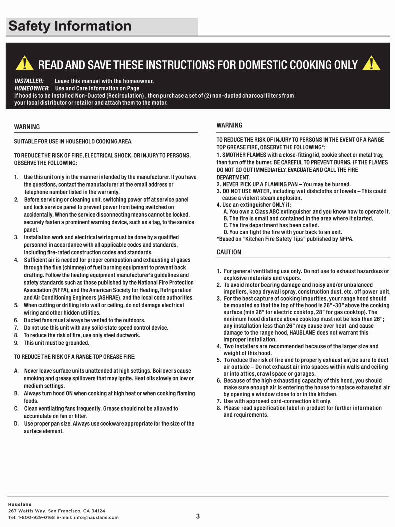
A READ AND SAVE THESE INSTRUCTIONS FOR DOMESTIC COOKING ONLY A INSTALLER: Leave this manual with the homeowner.
HOMEOWNER: Use and Care information on Page
If hood is to be installed Non-Ducted (Recirculation) , then purchase a set of (2) non-ducted charcoal filters from
your local distributor or retailer and attach them to the motor.
WARNING
SUITABLE FOR USE IN HOUSEHOLD COOKING AREA.
TO REDUCE THE RISK OF FIRE, ELECTRICAL SHOCK, OR INJURY TO PERSONS,
OBSERVE THE FOLLOWING:
1. Use this unit only in the manner intended by the manufacturer. If you have
the questions, contact the manufacturer at the email address or
telephone number listed in the warranty.
2. Before servicing or cleaning unit, switching power off at service panel
and lock service panel to prevent power from being switched on
accidentally. When the service disconnecting means cannot be locked,
securely fasten a prominent warning device, such as a tag, to the service
panel.
3. Installation work and electrical wiring must be done by a qualified
personnel in accordance with all applicable codes and standards,
including fire-rated construction codes and standards.
4. Sufficient air is needed for proper combustion and exhausting of gases
through the flue (chimney) of fuel burning equipment to prevent back
drafting. Follow the heating equipment manufacturer's guidelines and
safety standards such as those published by the National Fire Protection
Association (NFPA), and the American Society for Heating, Refrigeration
and Air Conditioning Engineers (ASH RAE), and the local code authorities.
5. When cutting or drilling into wall or ceiling, do not damage electrical
wiring and other hidden utilities.
6. Ducted fans must always be vented to the outdoors.
7. Do not use this unit with any solid-state speed control device.
8. To reduce the risk of fire, use only steel ductwork.
9. This unit must be grounded.
TO REDUCE THE RISK OF A RANGE TOP GREASE FIRE:
A. Never leave surface units unattended at high settings. Boil overs cause
smoking and greasy spillovers that may ignite. Heat oils slowly on low or
medium settings.
B. Always turn hood ON when cooking at high heat or when cooking flaming
foods.
C. Clean ventilating fans frequently. Grease should not be allowed to
accumulate on fan or filter.
D. Use proper pan size. Always use cookware appropriate for the size of the
surface element.
3
WARNING
TO REDUCE THE RISK OF INJURY TO PERSONS IN THE EVENT OF A RANGE
TOP GREASE FIRE, OBSERVE THE FOLLOWING*:
1. SMOTHER FLAMES with a close-fitting lid, cookie sheet or metal tray,
then turn off the burner. BE CAREFUL TO PREVENT BURNS. IF THE FLAMES
DO NOT GO OUT IMMEDIATELY, EVACUATE AND CALL THE FIRE
DEPARTMENT.
2. NEVER PICK UP A FLAMING PAN -You may be burned.
3. DO NOT USE WATER, including wet dishcloths or towels-This could
cause a violent steam explosion.
4. Use an extinguisher ONLY if:
A. You own a Class ABC extinguisher and you know how to operate it.
B. The fire is small and contained in the area where it started.
C. The fire department has been called.
D. You can fight the fire with your back to an exit.
*Based on "Kitchen Fire Safety Tips" published by NFPA.
CAUTION
1. For general ventilating use only. Do not use to exhaust hazardous or
explosive materials and vapors.
2. To avoid motor bearing damage and noisy and/or unbalanced
impellers, keep drywall spray, construction dust, etc. off power unit.
3. For the best capture of cooking impurities, your range hood should
be mounted so that the top of the hood is 26"-30" above the cooking
surface (min 26" for electric cooktop, 28" for gas cooktop). The
minimum hood distance above cooktop must not be less than 26";
any installation less than 26" may cause over heat and cause
damage to the range hood, HAUSLANE does not warrant this
improper installation.
4. Two installers are recommended because of the larger size and
weight of this hood.
5. To reduce the risk of fire and to properly exhaust air, be sure to duct
air outside -Do not exhaust air into spaces within walls and ceiling
or into attics, crawl space or garages.
6. Because of the high exhausting capacity of this hood, you should
make sure enough air is entering the house to replace exhausted air
by opening a window close to or in the kitchen.
7. Use with approved cord-connection kit only.8. Please read specification label in product for further information
and requirements.
Hauslane267 Wattis Way, San Francisco, CA 94124 Tel: 1-800-929-0168 E-mail: [email protected]
Warranty
This range hood is warranted to the original purchaser to be free of defects in material and workmanship for two(2)year from the date of purchase.
Our obligation shall be limited to the repair or replacement of a unit (at our discretion) that may prove, by our sole examination, to be defective under normal use and service during the warranty period. We may issue credit in the amount of the invoice value of the defective product (or a percentage of it according to use) in lieu of repair or replacement. Any failure of this product that is not traceable to a defect in material or workmanship is not covered by this warranty. These non-warrantable items include, but are not limited to:
□ Any defects or damage to light bulbs
□ Change in color or finish due to chemical usage
□ Improper installation not in accordance with the instructions
□ Dents, bumps, and scratches incurred during shipping, handling, or installation
□ Damage caused by failure to follow care and cleaning guidelines, including damage caused by the use of abrasive cleaners
□ Alterations made to the unit by the purchaser or installer
□ Damage caused by accidental impact, fire, flood, freezing, and normal wear
□ Bends and warping caused by forced connections, over-tightened fittings, and inadequate support during installation
A thorough inspection must be made before installation and any damage must be promptly reported. We will not be liable for failures or damage that could have been discovered or avoided by proper inspection and testing prior to installation.
Incidental repairs that would involve a minimum of time and effort on behalf of the purchaser will not be considered warranty work and no compensation will be deemed forth coming.
This warranty is non-transferable and shall be voided if the unit is removed from its initial installation or if it is not installed following the instructions.
Under no circumstance shall we be held liable for personal injury or property damage resulting from improper installation or use of this product. We
will not be held liable for inconvenience caused by loss of use of this product, costs incurred for labor or materials, removal and installation of
replacement units, or any other incidental or consequential damages. Costs relating to obtaining access for repair or replacement are the
responsibility of the user.
This warranty does not extend to commercial and institutional installation or use.
WARRANTY CLAIM PRODEDURE
If a claimable defect occurs, please contact our customer service team at 1-800-929-0168 (8 a.m. - 5 p.m., PST, Monday - Friday ).
Before you make your claim call, please ensure that you have:
□ Description of the range hood
□ Proof of sale
□ Details regarding the defect
□ Name(s) and address(es) of the owner and installer
Claims must be filled out in writing and returned within six (6) months of the appearance of a defect. Failure to comply with this stipulation will make this warranty null and void. We reserve the right to a thirty-day (30) delay following the receipt of a claim in which to inspect the product. We assume no responsibility for labor costs, removing or replacing a previously installed product, transportation, or the return of a product.
4
Hauslane267 Wattis Way, San Francisco, CA 94124 Tel: 1-800-929-0168 E-mail: [email protected]
Pre-installation
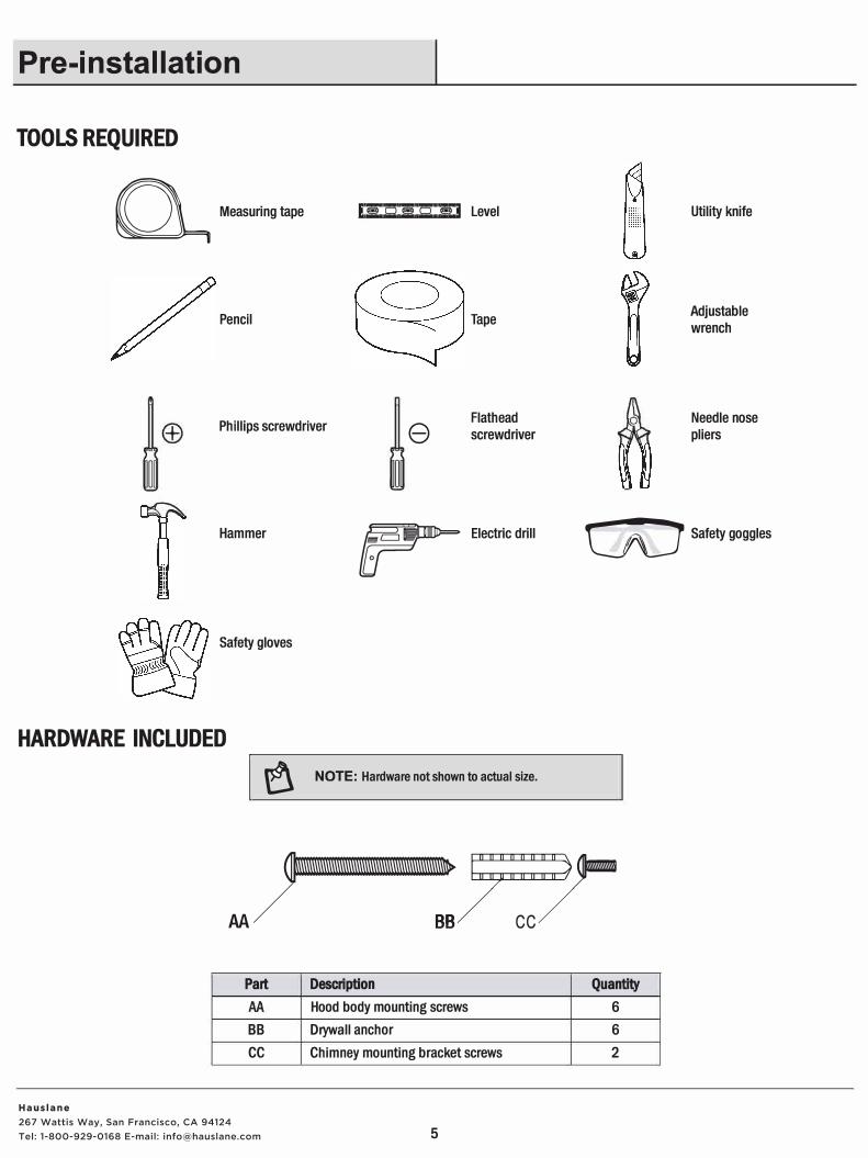
TOOLS REQUIRED
� Measuring tape
Pencil
Phillips screwdriver
�
Hammer
Safety gloves
HARDWARE INCLUDED
f !1,::::Q:::ll:::□::::::e!i,::8 Level
Tape
Flathead e screwdriver
�
�
Electric drill
I � NOTE, Haroware not shown to actual sl,e.
Utility knife
Adjustable wrench
Needle nose pliers
CD Safety goggles
��,-AA BB/ cc/
Part
BB
cc
Description Quantity
Hood body mounting screws 6 Drywall anchor 6 Chimney mounting bracket screws 2
5
Hauslane267 Wattis Way, San Francisco, CA 94124 Tel: 1-800-929-0168 E-mail: [email protected]
Pre-installation (continued)
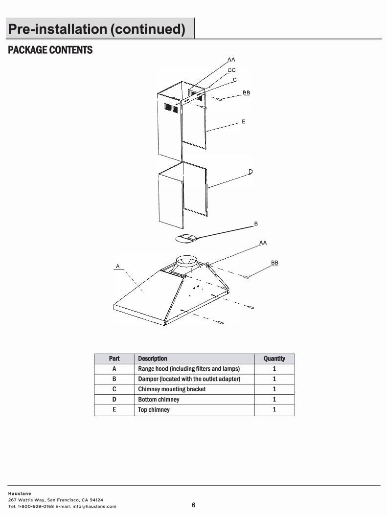
PACKAGE CONTENTS
Part
A
B
C
D
E
AA
E
�
B
AA
BB
Description Quantity
Range hood (including filters and lamps) 1
Damper (located with the outlet adapter) 1
Chimney mounting bracket 1
Bottom chimney 1
Top chimney 1
6
Hauslane267 Wattis Way, San Francisco, CA 94124 Tel: 1-800-929-0168 E-mail: [email protected]
Pre-installation {continued)
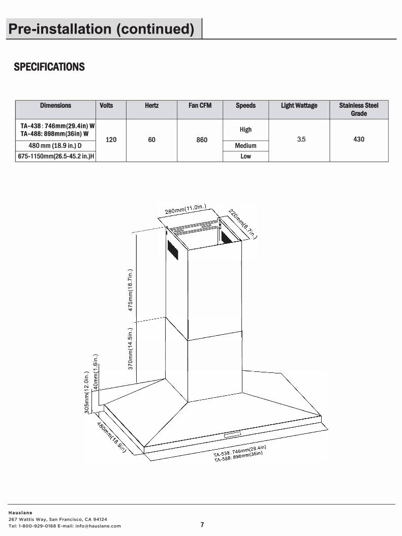
SPECIFICATIONS
Dimensions Volts
TA-438: 746mm(29.4in) W TA-488: 898mm(36in) W
120 480 mm (18.9 in.) D
675-1150mm(26.5-45.2 in.)H
�
C
I"--
00
�
E E
I"--
"""
�
C
"""
�
E
C E
0 I"--
�
C
0
N
Hertz FanCFM
60 860
7
Speeds Light Wattage Stainless Steel Grade
High
3.5 430 Medium
Low
Hauslane267 Wattis Way, San Francisco, CA 94124 Tel: 1-800-929-0168 E-mail: [email protected]
Calvin
Text Box
WM-538SS-30: 29.5in (W) WM-538SS-36: 35.5 (W)
Installation
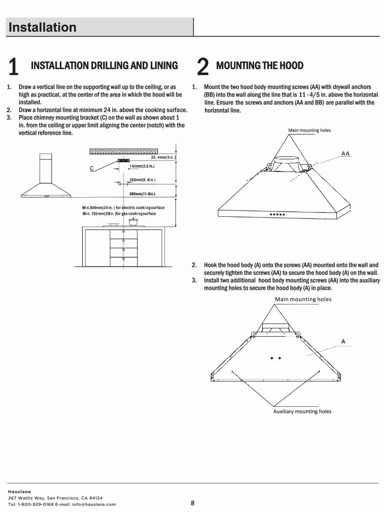
1 INSTALLATION DRILLING AND LINING 2 MOUNTING THE HOOD
1. Draw a vertical line on the supporting wall up to the ceiling, or as 1. Mount the two hood body mounting screws (AA) with drywall anchors
(BB) into the wall along the line that is 11-4/5 in. above the horizontal
line. Ensure the screws and anchors (AA and BB) are parallel with the
horizontal line.
high as practical, at the center of the area in which the hood will be
installed.
2. Draw a horizontal line at minimum 24 in. above the cooking surface.
3. Place chimney mounting bracket (C) on the wall as shown about 1
in. from the ceiling or upper limit aligning the center (notch) with the
vertical reference line.
j::::::::::::::::::::::: :j 25.4mm(1 in.)
__.-++-+-.,___2s
_om
_m
_(9
_.8
_in
_.)
__ _
t:::::=====::::l_ ______ ----l-___:::30::::0m
:::.:m
::.'..(1�1 .:::8i::,:,
n.)'.___ _ _Jl Min. 609mm(24 in.) for �lectric cooking surface
JMin.762mm(30 in.) for g,is cooking surface
_lr=t y
Q
Q
Main mounting holes
•••••
2. Hook the hood body (A) onto the screws (AA) mounted onto the wall and
securely tighten the screws (AA) to secure the hood body (A) on the wall.
3. Install two additional hood body mounting screws (AA) into the auxiliary
mounting holes to secure the hood body (A) in place.
Main mounting holes
Auxiliary mounting holes
8
Hauslane267 Wattis Way, San Francisco, CA 94124 Tel: 1-800-929-0168 E-mail: [email protected]
Installation (continued)
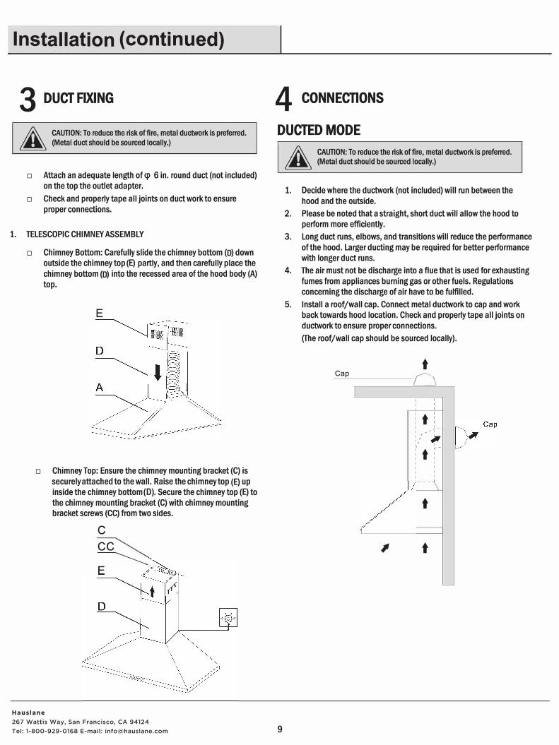
3 DUCT FIXING
;% CAUTION: To reduce the risk of fire, metal ductwork is preferred. � (Metal duct should be sourced locally.)
□ Attach an adequate length of cp 6 in. round duct (not included)on the top the outlet adapter.
□ Check and properly tape all joints on duct work to ensureproper connections.
1. TELESCOPIC CHIMNEY ASSEMBLY
□ Chimney Bottom: Carefully slide the chimney bottom (D) downoutside the chimney top (E) partly, and then carefully place thechimney bottom (D) into the recessed area of the hood body (A)top.
E
□ Chimney Top: Ensure the chimney mounting bracket (C) is
securely attached to the wall. Raise the chimney top (E) upinside the chimney bottom(D). Secure the chimney top (E) tothe chimney mounting bracket (C) with chimney mountingbracket screws (CC) from two sides.
C
cc
------=::.
4 CONNECTIONS
DUCTED MODE
9
;% CAUTION: To reduce the risk of fire, metal ductwork is preferred. � (Metal duct should be sourced locally.)
1. Decide where the ductwork (not included) will run between the
hood and the outside.
2. Please be noted that a straight, short duct will allow the hood toperform more efficiently.
3. Long duct runs, elbows, and transitions will reduce the performanceof the hood. Larger ducting may be required for better performancewith longer duct runs.
4. The air must not be discharge into a flue that is used for exhaustingfumes from appliances burning gas or other fuels. Regulationsconcerning the discharge of air have to be fulfilled.
5. Install a roof/wall cap. Connect metal ductwork to cap and workback towards hood location. Check and properly tape all joints onductwork to ensure proper connections.
(The roof/wall cap should be sourced locally).
t Cap �
- - -L_____'I,
t '
I � -1
:/, :, t
�-' '
' '
' '
' '
' '
' '
t
t
Hauslane267 Wattis Way, San Francisco, CA 94124 Tel: 1-800-929-0168 E-mail: [email protected]
Installation (continued)
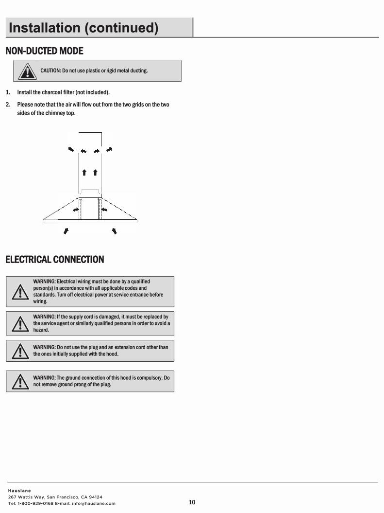
NON-DUCTED MODE
A CAUTION: Do not use plastic or rigid metal ducting.
1. Install the charcoal filter (not included).
2. Please note that the air will flow out from the two grids on the two
sides of the chimney top.
t t
ELECTRICAL CONNECTION
WARNING: Electrical wiring must be done by a qualified
person(s) in accordance with all applicable codes and
standards. Tum off electrical power at service entrance before
wiring.
WARNING: If the supply cord is damaged, it must be replaced by
the service agent or similarly qualified persons in order to avoid a
hazard.
WARNING: Do not use the plug and an extension cord other than
the ones initially supplied with the hood.
WARNING: The ground connection of this hood is compulsory. Do
not remove ground prong of the plug.
10
Hauslane267 Wattis Way, San Francisco, CA 94124 Tel: 1-800-929-0168 E-mail: [email protected]
Operation
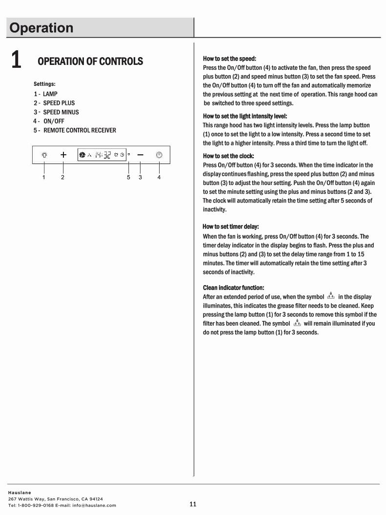
1 OPERATION OF CONTROLS
Settings: 1- LAMP2 - SPEED PLUS3 - SPEED MINUS4- ON/OFF5 - REMOTE CONTROL RECEIVER
I I I 2 5 3
I 4
11
How to set the speed:
Press the On/Off button (4) to activate the fan, then press the speed plus button (2) and speed minus button (3) to set the fan speed. Press the On/Off button (4) to turn off the fan and automatically memorize the previous setting at the next time of operation. This range hood can be switched to three speed settings.
How to set the light intensity level:
This range hood has two light intensity levels. Press the lamp button (1) once to set the light to a low intensity. Press a second time to setthe light to a higher intensity. Press a third time to turn the light off.
How to set the clock:
Press On/Off button (4) for 3 seconds. When the time indicator in the display continues flashing, press the speed plus button (2) and minus button (3) to adjust the hour setting. Push the On/Off button (4) again to set the minute setting using the plus and minus buttons (2 and 3). The clock will automatically retain the time setting after 5 seconds of inactivity.
How to set timer delay:
When the fan is working, press On/Off button (4) for 3 seconds. The timer delay indicator in the display begins to flash. Press the plus and minus buttons (2) and (3) to set the delay time range from 1 to 15 minutes. The timer will automatically retain the time setting after 3 seconds of inactivity.
Clean indicatorfunction:
After an extended period of use, when the symbol � in the display illuminates, this indicates the grease filter needs to be cleaned. Keep pressing the lamp button (1) for 3 seconds to remove this symbol if the filter has been cleaned. The symbol � will remain illuminated if you do not press the lamp button (1) for 3 seconds.
Hauslane267 Wattis Way, San Francisco, CA 94124 Tel: 1-800-929-0168 E-mail: [email protected]
Maintenance
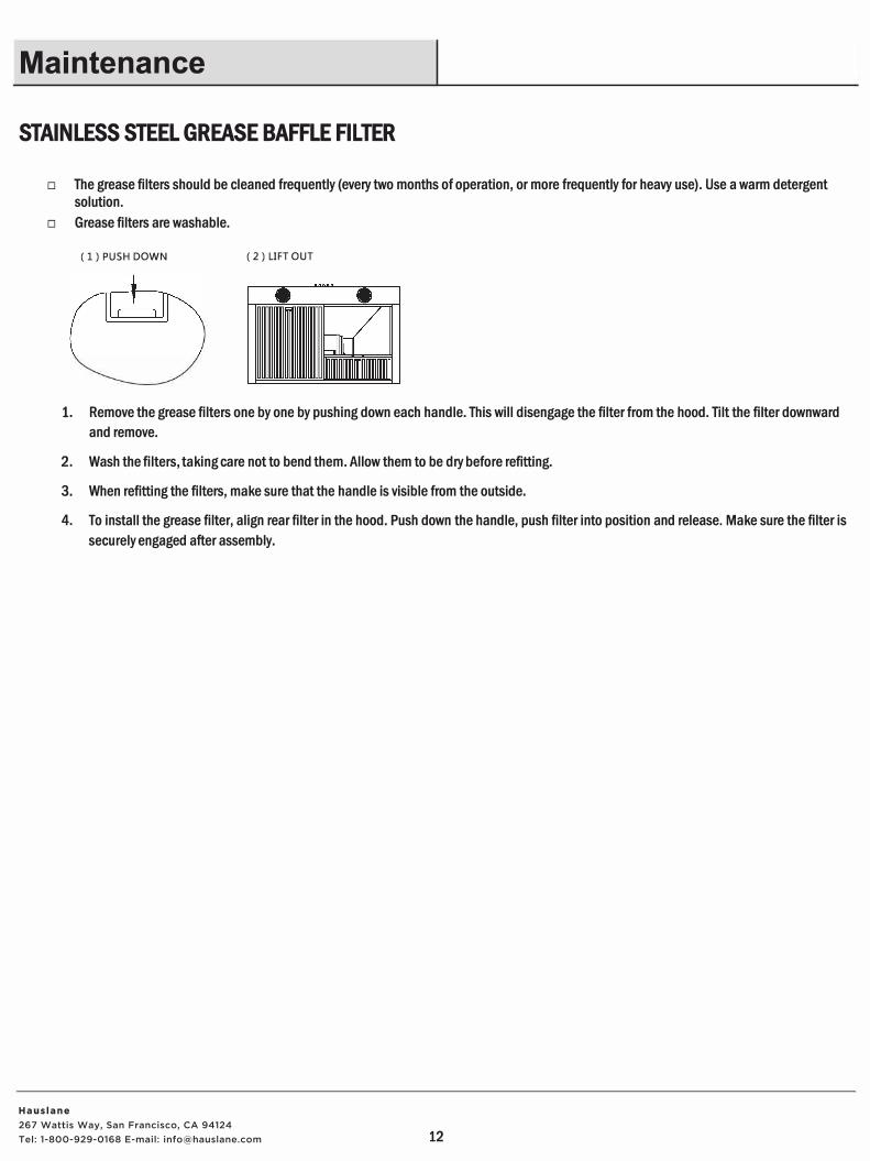
STAINLESS STEEL GREASE BAFFLE FILTER
□ The grease filters should be cleaned frequently (every two months of operation, or more frequently for heavy use). Use a warm detergent
solution.
□ Grease filters are washable.
( 1) PUSH DOWN ( 2) LIFT OUT
1. Remove the grease filters one by one by pushing down each handle. This will disengage the filter from the hood. Tilt the filter downward
and remove.
2. Wash the filters, taking care not to bend them. Allow them to be dry before refitting.
3. When refitting the filters, make sure that the handle is visible from the outside.
4. To install the grease filter, align rear filter in the hood. Push down the handle, push filter into position and release. Make sure the filter is
securely engaged after assembly.
12
Hauslane267 Wattis Way, San Francisco, CA 94124 Tel: 1-800-929-0168 E-mail: [email protected]
Maintenance (continued)
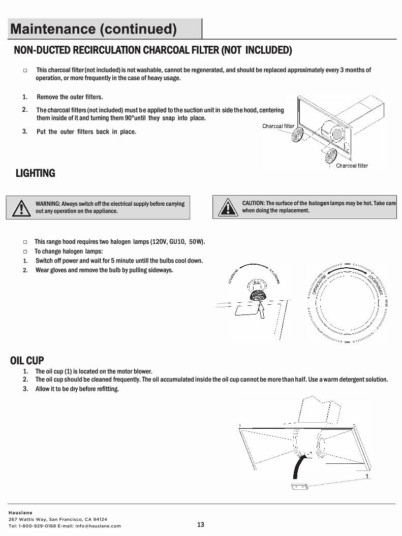
NON-DUCTED RECIRCULATION CHARCOAL FILTER {NOT INCLUDED)
□ This charcoal filter(not included) is not washable, cannot be regenerated, and should be replaced approximately every 3 months of
operation, or more frequently in the case of heavy usage.
1. Remove the outer filters.
2. The charcoal filters (not included) must be applied to the suction unit in side the hood, centering
them inside of it and turning them 90°until they snap into place.
3. Put the outer filters back in place.
LIGHTING
WARNING: Always switch off the electrical supply before carrying
out any operation on the appliance.
□ This range hood requires two halogen lamps (120V, GU 10, 50W).
□ To change halogen lamps:
1. Switch off power and wait for 5 minute untill the bulbs cool down.
2. Wear gloves and remove the bulb by pulling sideways.
OIL CUP 1. The oil cup (1) is located on the motor blower.
CAUTION: The surface of the halogen lamps may be hot Take care
when doing the replacement.
2. The oil cup should be cleaned frequently. The oil accumulated inside the oil cup cannot be more than half. Use a warm detergent solution.
3. Allow it to be dry before refitting.
13
Hauslane267 Wattis Way, San Francisco, CA 94124 Tel: 1-800-929-0168 E-mail: [email protected]
Care and Cleaning
J.\ WARNING: Failure to maintain basic standards of care and � cleaning of the range hood will increase the risk of fire .
The range hood should be cleaned regularly internally and externally to preserve its appearance and performance.
Do □ Clean the range hood periodically with hot, soapy
water and a clean cotton cloth.□ Always clean in the direction of original polish lines.□ Always rinse well with clean water two or three
times after cleaning. Wipe completely dry with asoft, non-abrasive cloth.
□ After cleaning, you may polish with a non-abrasivestainless steel polish or cleaner. Always rub lightlyand with the grain.
□ Ensure that the venting system is free of debris, ifyou have one.
14
Do Not □ Do not use corrosive or abrasive detergents, or any
products containing chloride, fluoride, iodide, orbromide on this product, as they will deteriorate thesurface rapidly.
□ Do not allow cleaning compounds, salt solutions,disinfectants, or bleaches to remain in contact withthe product for extended periods of time.
□ Do not allow deposits to remain for long periods oftime on the range hood. Rinse with water immediatelyand wipe dry with a clean cloth.
□ Do not leave the range hood dirty for long periods oftime or allow dirt to accumulate.
□ Do not let plaster dust or any other constructionresidue enter the hood. During construction orrenovation, cover the hood.
□ Combustible products used for cleaning, such asacetone, alcohol, ether, or benzyl, are highly explosiveand should never be used close to a range or stove .
Hauslane267 Wattis Way, San Francisco, CA 94124 Tel: 1-800-929-0168 E-mail: [email protected]
Troubleshooting
A
Problem
DANGER: Tum off the power circuit breaker or the power switch
on the Junction box before Installing or servicing this unit.
Touching circuitry inside the range hood while it is energized will
result in death or serious injury.
The range hood will not operate.
The range hood vibrates when the fan is operating.
The fans seem weak.
The lights work, but the fan is not spinning, is stuck, or is rattling.
The range hood is not venting properly.
A light does not work.
Solution
□ Check that the power supply cable and all electrical wiring are properly
connected.
□ Check that the power is turned on at the junction box or circuit breaker.
□ Check that the wiring between the switch board and the control board are
connected properly.
□ Check that the range hood has been secured properly to the wall or cabinet.
Tighten it into position, if necessary.
□ Check that the motor is secured in place. If not, then tighten the motor in
place.
□ Check that the fan is not damaged. If so, replace the fan.
□ Check that the duct size used is at least 152 mm (6 in.). The range hood will
not function efficiently with insufficient duct size.
□ Check that the duct is not clogged with debris and the tight mesh on the
wall cap, if applicable, isn't restricting air flow.
□ Check that the damper unit is opening properly, if applicable.
□ The lights work, but the fan is not spinning, is stuck, or is rattling.
□ Check that the fan isn't jammed or scraping the bottom.
□ If nothing else works, the motor may be defective or seized. If so, replace the
motor.
□ Check that the distance between the cook top and the bottom of the range
hood is min. at 24 in.
□ Check that duct work follows all requirements. Use metal duct work with a
uniform diameter of 150 mm (6 in.). Reduce the length of duct work and the
number of elbows if necessary. Ensure that all joints are properly connected,
sealed, and taped.
□ Check that the duct does not open against the wind.
□ Ensure that the power is on high speed for heavy cooking.
□ Wind from opened windows or doors may affect the performance of the
range hood. Close windows and doors to eliminate outside air flow.
□ Check the light bulb to see if it is loose. If so, tighten.
□ Remove the problem bulb and insert one you know is working. If the properlyfunctioning light does not come on, the problem may be the light assembly.
Have the light assembly serviced or replaced.
15
Hauslane267 Wattis Way, San Francisco, CA 94124 Tel: 1-800-929-0168 E-mail: [email protected]
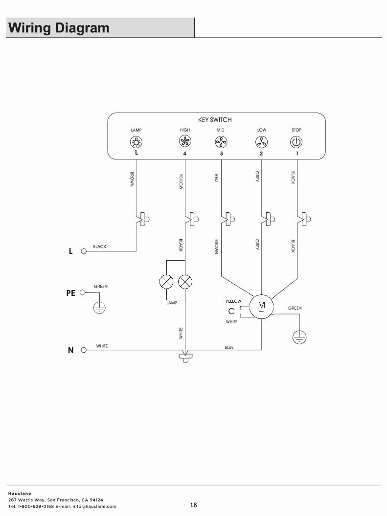
Wiring Diagram
L BLACK
GREEN
PE
�
N WHITE
LAMP
@ L
"' 0 ::;:
HIGH
®b
4
;:'i
5 ::;:
LAMP
16
KEY SWITCH
MID
EB 3
� 0
C
WHITE
BLUE
LOW
®
G)
� -<
G) "' m -<
2
STOP
@)
► 0
GREEN
Hauslane267 Wattis Way, San Francisco, CA 94124 Tel: 1-800-929-0168 E-mail: [email protected]
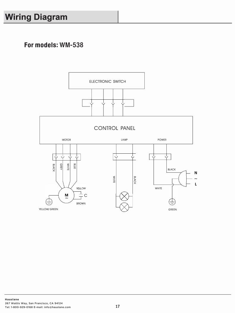
Wiring Diagram
For models: WM-538
MOTOR
CD (j) ::;: � s;: Al I C
m =a m 0 -< m
;,s
YELLOW/ GREEN
ELECTRONIC SWITCH
CONTROL PANEL
LAMP
::;: CD
s;: =a 0 m
;,s
C
17
POWER
BLACK
WHITE
GREEN
Hauslane267 Wattis Way, San Francisco, CA 94124 Tel: 1-800-929-0168 E-mail: [email protected]