Instruction Sheet B2000 Cyclone Bender...pulling the spring loaded pin on the side of the bender...
6
RPS-0097 01/02 Effective for models with serial numbers beginning with "G". Instruction Sheet B2000 Cyclone ® Bender IMPORTANT RECEIVING INSTRUCTIONS Visually inspect all components for shipping damage. If shipping damage is found, notify carrier at once. Shipping damage is NOT covered by warranty.The carrier is responsible for all repair and replacement costs resulting from damage in shipment. SAFETY ISSUES IMPORTANT – USER SAFETY AND PROTECTION: In setting up systems to fit your operations, care must be taken to select the proper components and design to insure appropriate that all safety measures have been taken to avoid the risk of personal injury and property damage from your application or system. GARDNER BENDER IS NOT RESPONSIBLE FOR DAMAGE OR INJURY CAUSED BY UNSAFE USE, MAINTENANCE OR THE APPLICATION OF ITS PRODUCTS. Please contact Gardner Bender for guidance when you are in doubt as to the proper safety precautions to be taken in designing and setting up your particular application. 1.0 DESCRIPTION The Cyclone ® , GB model B2000 production bender is used to bend EMT, IMC, rigid steel or rigid aluminum conduit. A single bending shoe accommodates sizes 1 / 2", 3 / 4", 1", 1 1 / 4", 1 1 / 2" and 2" conduit.The shoe is driven by a 115 V, 15 A motor.The roller housing consists of a single urethane roller support arm, and three sets of nylon rollers. The bender control pendant consists of a zero light, a jog push button, a two-position toggle switch for “Bend and Return”, resettable circuit breaker and ON/OFF switch. An 8' electrical cord connects the pendant to the bender frame. The bender can be used in a horizontal or vertical position. To avoid damaging the bender control circuit, an input voltage sensing system is built into the control circuit. If input voltage is less than 92 VAC or higher than 132 VAC the bender will shut off. One of the two LEDS located on the end plate will light to indicate whether high or low voltage exists. Re-set the bender by turning unit off then on again. If the incoming current voltage has not been corrected, the bender will continue to not operate. The voltage range must be within 92 VAC to 132 VAC. Any situation which causes a voltage drop or increase must be corrected before using the B2000 Bender. Voltage drops may be caused by: • Extension cords that are too long. • Extension cords made of light (16-18 gauge) wire. • Multiple power tools on a single circuit. • Other devices which require high amperes to operate. 2.0 WARNINGS CAUTION: During pipe bending, stand behind the frame handle. Keep hands, clothing and control cord away from the bending shoe and rollers. WARNING: Do not operate the bender on damp or wet surfaces. Do not stand on wet surfaces while operating the bender. CAUTION: To prevent damage to the bending shoe, do not allow the clamping jaws to strike the upper roller support arm when the shoe is rotating. Position the roller housing against the frame stop. See Figure 1. CAUTION: Select an operating area large enough to permit loading pipe section and bending without striking objects or personnel. WARNING: To avoid possible injury, do not place fingers under the bottom edge of the bending shoe. See Figure 2. CAUTION: Do not attempt to bend conduit or pipe other than 1 / 2" through 2" IMC, EMT, rigid steel or aluminum. Bending other materials will damage the bender and void the warranty. Bending Shoe Pendant Control High/Low Voltage Indicator Frame Stop Upper Roller
Transcript of Instruction Sheet B2000 Cyclone Bender...pulling the spring loaded pin on the side of the bender...
RPS-0097 01/02 Effective for models with serial numbers beginning with "G".
Instruction Sheet
B2000 Cyclone® Bender
IMPORTANT RECEIVING INSTRUCTIONS
Visually inspect all components for shipping damage. If shipping damage is found, notify carrier at once. Shipping damage is NOTcovered by warranty. The carrier is responsible for all repair and replacement costs resulting from damage in shipment.
SAFETY ISSUES
IMPORTANT – USER SAFETY AND PROTECTION: In setting up systems to fit your operations, care must be taken to select theproper components and design to insure appropriate that all safety measures have been taken to avoid the risk of personal injuryand property damage from your application or system.
GARDNER BENDER IS NOT RESPONSIBLE FOR DAMAGE OR INJURY CAUSED BY UNSAFE USE, MAINTENANCE OR THEAPPLICATION OF ITS PRODUCTS. Please contact Gardner Bender for guidance when you are in doubt as to the proper safetyprecautions to be taken in designing and setting up your particular application.
1.0 DESCRIPTIONThe Cyclone®, GB model B2000 production bender is used tobend EMT, IMC, rigid steel or rigid aluminum conduit. A singlebending shoe accommodates sizes 1⁄ 2", 3⁄ 4", 1", 11⁄ 4", 11⁄ 2" and2" conduit.The shoe is driven by a 115 V, 15 A motor.The rollerhousing consists of a single urethane roller support arm, andthree sets of nylon rollers.The bender control pendant consists of a zero light, a jog pushbutton, a two-position toggle switch for “Bend and Return”,resettable circuit breaker and ON/OFF switch. An 8' electricalcord connects the pendant to the bender frame. The bendercan be used in a horizontal or vertical position.To avoid damaging the bender control circuit, an input voltagesensing system is built into the control circuit. If input voltageis less than 92 VAC or higher than 132 VAC the bender willshut off. One of the two LEDS located on the end plate will lightto indicate whether high or low voltage exists.
Re-set the bender by turning unit off then on again. If theincoming current voltage has not been corrected, the benderwill continue to not operate. The voltage range must be within92 VAC to 132 VAC. Any situation which causes a voltage dropor increase must be corrected before using the B2000 Bender.
Voltage drops may be caused by:• Extension cords that are too long.• Extension cords made of light (16-18 gauge) wire.• Multiple power tools on a single circuit.• Other devices which require high amperes to operate.
2.0 WARNINGS
CAUTION: During pipe bending, stand behind theframe handle. Keep hands, clothing and control cord awayfrom the bending shoe and rollers.
WARNING: Do not operate the bender on damp orwet surfaces. Do not stand on wet surfaces whileoperating the bender.
CAUTION: To prevent damage to the bending shoe,do not allow the clamping jaws to strike the upper rollersupport arm when the shoe is rotating. Position the rollerhousing against the frame stop. See Figure 1.
CAUTION: Select an operating area large enough topermit loading pipe section and bending without strikingobjects or personnel.
WARNING: To avoid possible injury, do not placefingers under the bottom edge of the bending shoe. SeeFigure 2.
CAUTION: Do not attempt to bend conduit or pipeother than 1⁄ 2" through 2" IMC, EMT, rigid steel oraluminum. Bending other materials will damage thebender and void the warranty.
Bending Shoe
PendantControl
High/Low Voltage
Indicator
Frame Stop
Upper Roller
NOTE: All operations referring to “toward the operator”are viewed from the lifting handle end of the bender frame.
3.0 SPECIFICATIONSPower Source .....................................120 V 60 cycle ACPendant Control Circuit ......................12 VDCMotor ..................................................1 HP 100 V 60 cycle DCWeight ................................................345 lbs.Height .................................................38 inchesWidth ..................................................31 inchesLength.................................................45 inchesCircuit Breaker....................................15 AmpBend Capability ..................................1⁄2" - 2" IMC, EMT
Rigid Steel or Rigid Aluminum
4.0 OPERATION4.1 Bending 1⁄ 2", 3⁄ 4" and 1" IMC, EMT and
rigid conduit:1. Position the bender in a level dry area large enough to
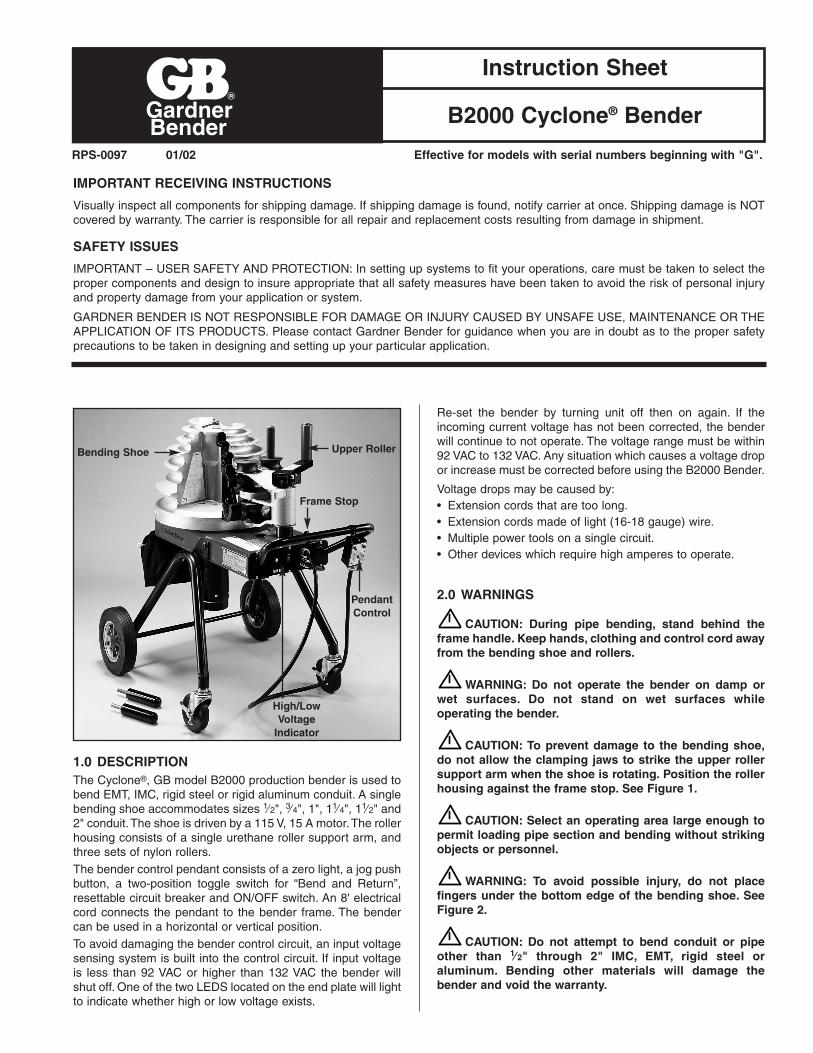
permit loading and unloading various lengths of conduit.Position the frame, either horizontally or vertically, bypulling the spring loaded pin on the side of the benderframe. See Figure 1.
Figure 1. Vertical Position
2. Identify the type (IMC, EMT or Rigid) and size conduit tobe bent.
3. Locate the markings that indicate which grooves are usedfor specific materials, and which grooves are used forspecific size conduit. See Figure 2.
Figure 2. Set Up
CAUTION: To avoid damaging the rollers and rollerhousing, always place the roller housing against theframe stop prior to rotating the shoe.
4. Push the roller housing against the frame stop.See Figure 2. Rotate the shoe to bring the requiredgrooves (EMT, IMC or Rigid) facing toward the operator.To activate the shoe, hold the pendant toggle switch in“Return” and press the jog button until the zero light goesout. The shoe will rotate and stop in the load position. Thezero light will come on.
5. The upper urethane roller and support arm (See Figure 3) is used for bending 1⁄2" through 1" conduit. One of the top three shoe grooves will be used, depending on conduit size.
Figure 3. Bending 1/2" - 1"
2
Support Arm
Positioning Pin
Upper Roller
Roller Housing
Frame Stop
Material Identifier
Frame Stop
Jaw
Bend Groove
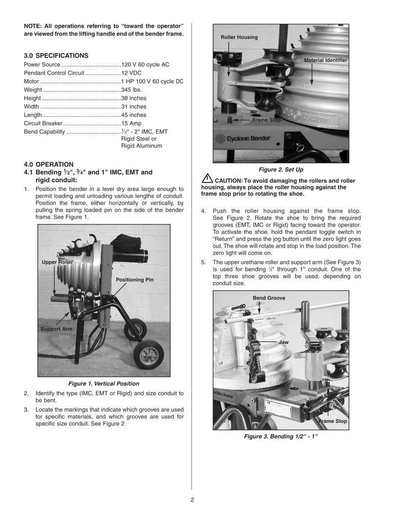
6. When bending 1⁄2" - 1" conduit the upper roller and supportarm must be positioned between the shoe and the rollerhousing. Position the urethane roller by moving the rollerhousing against the frame stop and removing the pin.
7. Lift the roller support arm to clear the nylon rollers andswing the arm (toward shoe) over the roller housing.Lower the arm into the support bracket and insert the ringpin. See Figure 4.
Figure 4. Position Roller Support
8. Insert the conduit in the shoe groove marked with thenumber matching the size conduit being bent. The conduitmust set in the shoe and in the jaw. The end of the conduitmust extend a minimum of 2" beyond the jaw. See Figure3. Refer to table A or B on page 5 for bending data.
9. Each time a different size and type of conduit is beingbent, three facts must be determined and set into thebender shoe control system. The required settings are:conduit size, material and desired bend angle. Prior tosetting, be sure the desired size indicator scale is towardthe operator and the correct shoe grooves are also towardthe operator.
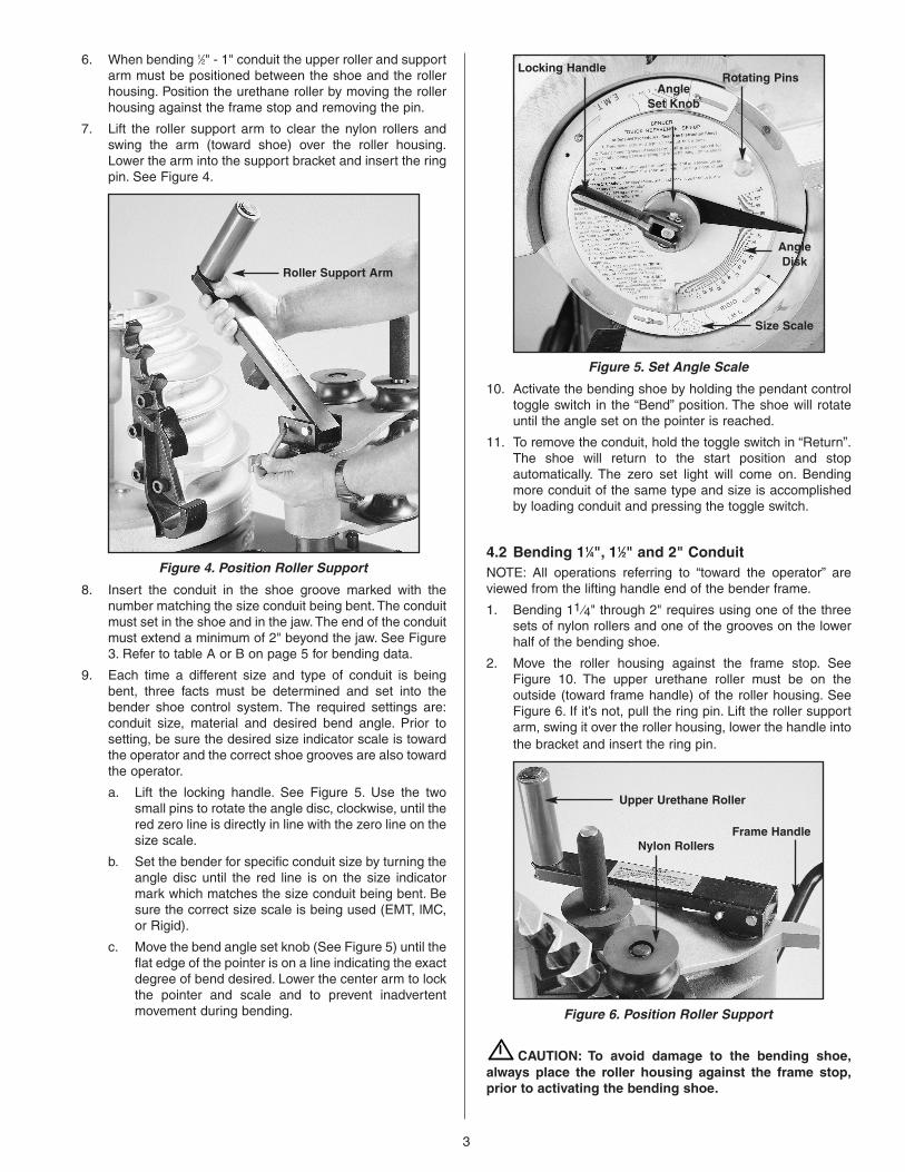
a. Lift the locking handle. See Figure 5. Use the twosmall pins to rotate the angle disc, clockwise, until thered zero line is directly in line with the zero line on thesize scale.
b. Set the bender for specific conduit size by turning theangle disc until the red line is on the size indicatormark which matches the size conduit being bent. Besure the correct size scale is being used (EMT, lMC,or Rigid).
c. Move the bend angle set knob (See Figure 5) until theflat edge of the pointer is on a line indicating the exactdegree of bend desired. Lower the center arm to lockthe pointer and scale and to prevent inadvertentmovement during bending.
Figure 5. Set Angle Scale
10. Activate the bending shoe by holding the pendant controltoggle switch in the “Bend” position. The shoe will rotateuntil the angle set on the pointer is reached.
11. To remove the conduit, hold the toggle switch in “Return”.The shoe will return to the start position and stopautomatically. The zero set light will come on. Bendingmore conduit of the same type and size is accomplishedby loading conduit and pressing the toggle switch.
4.2 Bending 11⁄4", 11⁄2" and 2" ConduitNOTE: All operations referring to “toward the operator” areviewed from the lifting handle end of the bender frame.
1. Bending 11 ⁄4" through 2" requires using one of the threesets of nylon rollers and one of the grooves on the lowerhalf of the bending shoe.
2. Move the roller housing against the frame stop. SeeFigure 10. The upper urethane roller must be on theoutside (toward frame handle) of the roller housing. SeeFigure 6. If it’s not, pull the ring pin. Lift the roller supportarm, swing it over the roller housing, lower the handle intothe bracket and insert the ring pin.
Figure 6. Position Roller Support
CAUTION: To avoid damage to the bending shoe,always place the roller housing against the frame stop,prior to activating the bending shoe.
3
Roller Support Arm
Locking Handle
AngleDisk
Size Scale
AngleSet Knob
Rotating Pins
Frame HandleNylon Rollers
Upper Urethane Roller
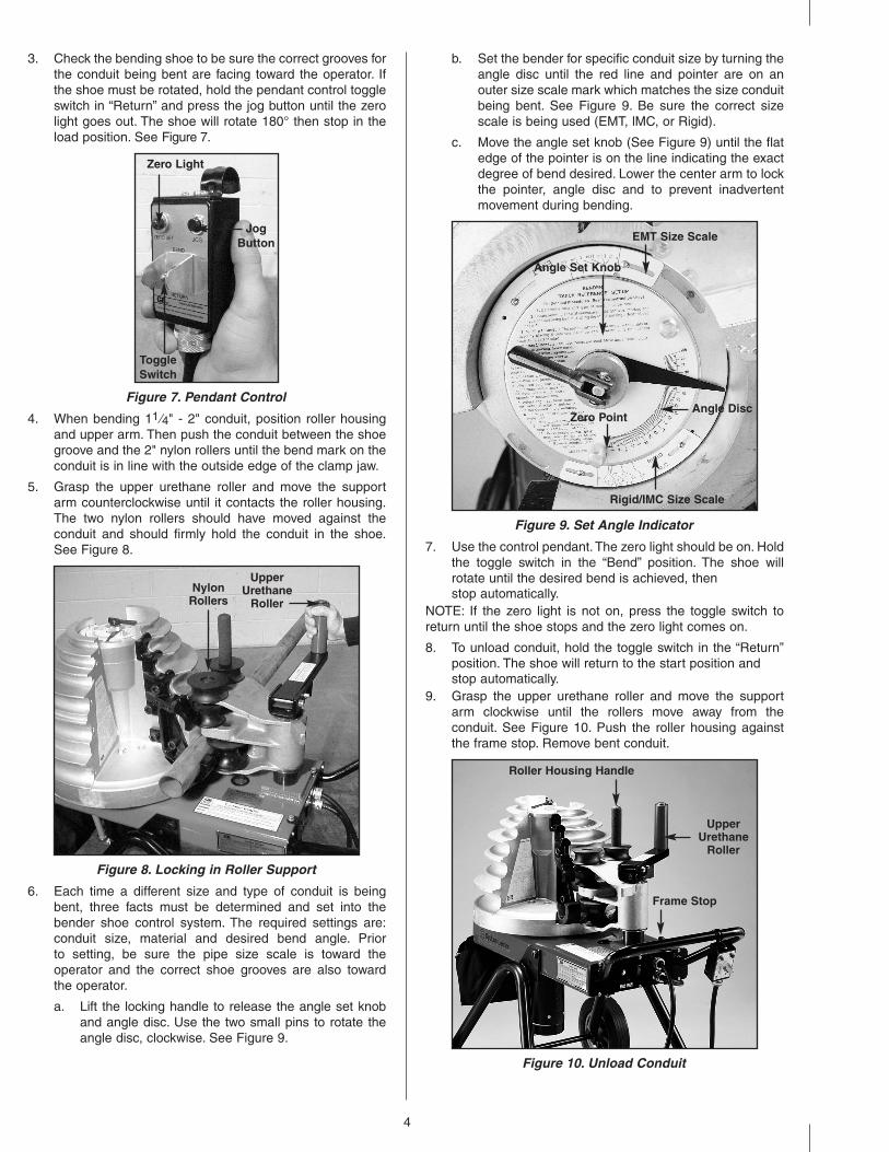
3. Check the bending shoe to be sure the correct grooves forthe conduit being bent are facing toward the operator. Ifthe shoe must be rotated, hold the pendant control toggleswitch in “Return” and press the jog button until the zerolight goes out. The shoe will rotate 180° then stop in theload position. See Figure 7.
Figure 7. Pendant Control
4. When bending 11 ⁄4" - 2" conduit, position roller housingand upper arm. Then push the conduit between the shoegroove and the 2" nylon rollers until the bend mark on theconduit is in line with the outside edge of the clamp jaw.
5. Grasp the upper urethane roller and move the supportarm counterclockwise until it contacts the roller housing.The two nylon rollers should have moved against theconduit and should firmly hold the conduit in the shoe.See Figure 8.
Figure 8. Locking in Roller Support
6. Each time a different size and type of conduit is beingbent, three facts must be determined and set into thebender shoe control system. The required settings are:conduit size, material and desired bend angle. Prior to setting, be sure the pipe size scale is toward theoperator and the correct shoe grooves are also toward the operator.
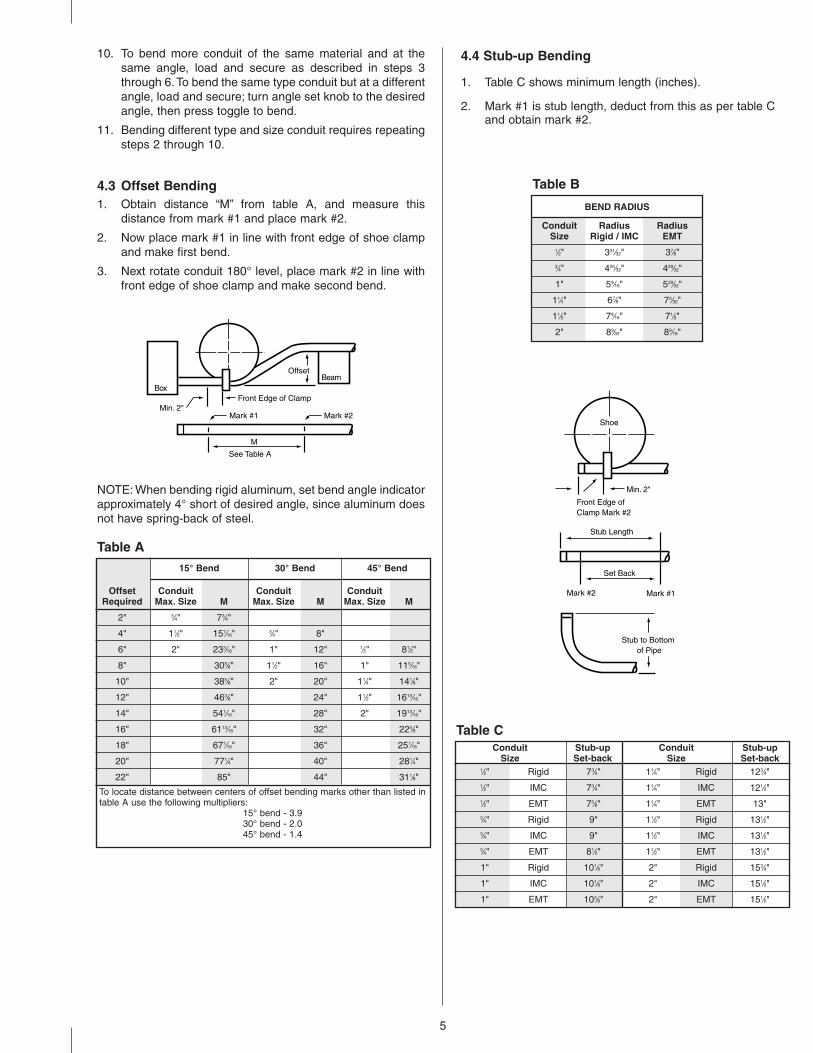
a. Lift the locking handle to release the angle set knoband angle disc. Use the two small pins to rotate theangle disc, clockwise. See Figure 9.
b. Set the bender for specific conduit size by turning theangle disc until the red line and pointer are on anouter size scale mark which matches the size conduitbeing bent. See Figure 9. Be sure the correct sizescale is being used (EMT, lMC, or Rigid).
c. Move the angle set knob (See Figure 9) until the flatedge of the pointer is on the line indicating the exactdegree of bend desired. Lower the center arm to lockthe pointer, angle disc and to prevent inadvertentmovement during bending.
Figure 9. Set Angle Indicator
7. Use the control pendant. The zero light should be on. Holdthe toggle switch in the “Bend” position. The shoe willrotate until the desired bend is achieved, then stop automatically.
NOTE: If the zero light is not on, press the toggle switch toreturn until the shoe stops and the zero light comes on.
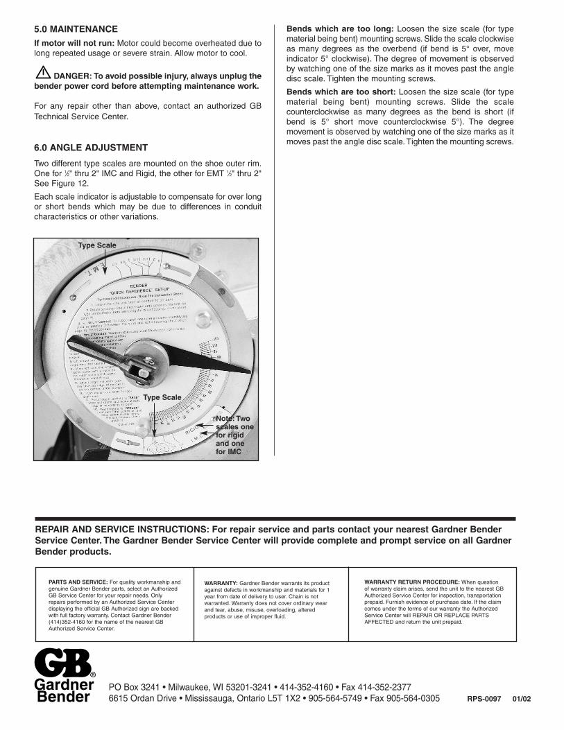
8. To unload conduit, hold the toggle switch in the “Return”position. The shoe will return to the start position and stop automatically.
9. Grasp the upper urethane roller and move the supportarm clockwise until the rollers move away from theconduit. See Figure 10. Push the roller housing againstthe frame stop. Remove bent conduit.
Figure 10. Unload Conduit
4
Zero Light
ToggleSwitch
JogButton
UpperUrethane
RollerNylon
Rollers
Zero Point
Rigid/IMC Size Scale
Angle Disc
Angle Set Knob
EMT Size Scale
Frame Stop
UpperUrethane
Roller
Roller Housing Handle
10. To bend more conduit of the same material and at thesame angle, load and secure as described in steps 3through 6.To bend the same type conduit but at a differentangle, load and secure; turn angle set knob to the desiredangle, then press toggle to bend.
11. Bending different type and size conduit requires repeatingsteps 2 through 10.
4.3 Offset Bending1. Obtain distance “M” from table A, and measure this
distance from mark #1 and place mark #2.
2. Now place mark #1 in line with front edge of shoe clampand make first bend.
3. Next rotate conduit 180° level, place mark #2 in line withfront edge of shoe clamp and make second bend.
NOTE: When bending rigid aluminum, set bend angle indicatorapproximately 4° short of desired angle, since aluminum doesnot have spring-back of steel.
4.4 Stub-up Bending
1. Table C shows minimum length (inches).
2. Mark #1 is stub length, deduct from this as per table Cand obtain mark #2.
OffsetBeam
Box
M
Front Edge of Clamp
See Table A
Min. 2"Mark #2Mark #1
5
Offset Conduit Conduit ConduitRequired Max. Size M Max. Size M Max. Size M
2" 3⁄4" 73⁄4"
4" 11⁄2" 157⁄16" 3⁄4" 8"
6" 2" 233⁄16" 1" 12" 1⁄2" 81⁄2"
8" 305⁄8" 11⁄2" 16" 1" 115⁄16"
10" 385⁄8" 2" 20" 11⁄4" 141⁄8"
12" 463⁄8" 24" 11⁄2" 1615⁄16"
14" 541⁄16" 28" 2" 1913⁄16"
16" 6113⁄16" 32" 225⁄8"
18" 677⁄16" 36" 257⁄16"
20" 771⁄4" 40" 281⁄4"
22" 85" 44" 311⁄8"
To locate distance between centers of offset bending marks other than listed intable A use the following multipliers:
15° bend - 3.930° bend - 2.045° bend - 1.4
Table A
15° Bend 30° Bend 45° Bend
Shoe
Min. 2"
Stub Length
Set Back
Mark #2 Mark #1
Front Edge of Clamp Mark #2
Stub to Bottom of Pipe
Conduit Radius RadiusSize Rigid / IMC EMT
1⁄2" 331⁄32" 37⁄8"3⁄4" 425⁄32" 429⁄32"
1" 59⁄16" 529⁄32"
11⁄4" 67⁄8" 73⁄32"
11⁄2" 79⁄16" 71⁄2"
2" 89⁄32" 89⁄16"
Table B
BEND RADIUS
1⁄2" Rigid 73⁄4" 11⁄4" Rigid 123⁄4"1⁄2" IMC 73⁄4" 11⁄4" IMC 121⁄2"1⁄2" EMT 75⁄8" 11⁄4" EMT 13"3⁄4" Rigid 9" 11⁄2" Rigid 131⁄2"3⁄4" IMC 9" 11⁄2" IMC 131⁄2"3⁄4" EMT 81⁄2" 11⁄2" EMT 131⁄2"
1" Rigid 101⁄8" 2" Rigid 153⁄4"
1" IMC 101⁄8" 2" IMC 151⁄2"
1" EMT 103⁄8" 2" EMT 151⁄2"
Table CConduit Stub-up Conduit Stub-up
Size Set-back Size Set-back
GardnerBender RPS-0097 01/02
PO Box 3241 • Milwaukee, WI 53201-3241 • 414-352-4160 • Fax 414-352-23776615 Ordan Drive • Mississauga, Ontario L5T 1X2 • 905-564-5749 • Fax 905-564-0305
5.0 MAINTENANCE
If motor will not run: Motor could become overheated due tolong repeated usage or severe strain. Allow motor to cool.
DANGER: To avoid possible injury, always unplug thebender power cord before attempting maintenance work.
For any repair other than above, contact an authorized GBTechnical Service Center.
6.0 ANGLE ADJUSTMENT
Two different type scales are mounted on the shoe outer rim.One for 1⁄2" thru 2" IMC and Rigid, the other for EMT 1⁄2" thru 2"See Figure 12.
Each scale indicator is adjustable to compensate for over longor short bends which may be due to differences in conduitcharacteristics or other variations.
Bends which are too long: Loosen the size scale (for typematerial being bent) mounting screws. Slide the scale clockwiseas many degrees as the overbend (if bend is 5° over, moveindicator 5° clockwise). The degree of movement is observedby watching one of the size marks as it moves past the angledisc scale. Tighten the mounting screws.
Bends which are too short: Loosen the size scale (for typematerial being bent) mounting screws. Slide the scalecounterclockwise as many degrees as the bend is short (ifbend is 5° short move counterclockwise 5°). The degreemovement is observed by watching one of the size marks as itmoves past the angle disc scale. Tighten the mounting screws.
Note: Twoscales onefor rigidand onefor IMC
Type Scale
Type Scale
WARRANTY: Gardner Bender warrants its productagainst defects in workmanship and materials for 1year from date of delivery to user. Chain is notwarranted. Warranty does not cover ordinary wearand tear, abuse, misuse, overloading, alteredproducts or use of improper fluid.
WARRANTY RETURN PROCEDURE: When question of warranty claim arises, send the unit to the nearest GBAuthorized Service Center for inspection, transportationprepaid. Furnish evidence of purchase date. If the claimcomes under the terms of our warranty the AuthorizedService Center will REPAIR OR REPLACE PARTSAFFECTED and return the unit prepaid.
PARTS AND SERVICE: For quality workmanship andgenuine Gardner Bender parts, select an AuthorizedGB Service Center for your repair needs. Only repairs performed by an Authorized Service Centerdisplaying the official GB Authorized sign are backedwith full factory warranty. Contact Gardner Bender(414)352-4160 for the name of the nearest GBAuthorized Service Center.
REPAIR AND SERVICE INSTRUCTIONS: For repair service and parts contact your nearest Gardner BenderService Center. The Gardner Bender Service Center will provide complete and prompt service on all GardnerBender products.