INSTRUCTION OF USE - Om Spännare, Originalet … · If gripper is not working properly refer...
19
17 avenue des Grenots F-91150 ETAMPES Tél. : +33 (0)1 69 92 16 16 Fax : +33 (0) 1 64 94 21 35 Email : [email protected] Website : http://www.joulin.com INSTRUCTION OF USE “Low vacuum handling specialist since 1969, JOULIN AERO introduces UNILIFT: The Universal Vacuum Handler. Patented auto-regulated valves allow UNILIFT to handle, without adjustment, products and their packaging. Designed in aluminum and equipped with the best components, UNILIFT is designed for both Robotics integrators & Gantry system providers. Ideal tool for end of line automation, UNILIFT may surprise you with its versatility.”
Transcript of INSTRUCTION OF USE - Om Spännare, Originalet … · If gripper is not working properly refer...

17 avenue des Grenots
F-91150 ETAMPES
Tél. : +33 (0)1 69 92 16 16
Fax : +33 (0) 1 64 94 21 35
Email : [email protected]
Website : http://www.joulin.com
INSTRUCTION OF USE
“Low vacuum handling specialist since 1969, JOULIN AERO introduces UNILIFT: The Universal
Vacuum Handler. Patented auto-regulated valves allow UNILIFT to handle, without adjustment,
products and their packaging. Designed in aluminum and equipped with the best components,
UNILIFT is designed for both Robotics integrators & Gantry system providers. Ideal tool for end of
line automation, UNILIFT may surprise you with its versatility.”

Instruction of use demonstration box JOULIN
Page 2 sur 19
SUMMARY
I. GENERAL SCHEME OF GRIPPING SYSTEM _________________________________________ 3
TC (Check valve version) : ________________________________________________________________ 3
TL (Metered port version) : _______________________________________________________________ 3
EXPLODED VIEW ________________________________________________________________________ 4
II. IMPORTANT ADVICES _________________________________________________________ 5
III. VACUUM GRIPPER INSTRUCTIONS OF USE ________________________________________ 6
STARTUP ______________________________________________________________________________ 6
GENERAL FUNCTIONING _________________________________________________________________ 6
PICK UP / RELEASE SCHEME _______________________________________________________________ 7
IV. SERVICE AND MAINTENANCE ___________________________________________________ 8
GENERAL ADVICE _______________________________________________________________________ 8
JOULIN AERO VACUUM GAUGE ____________________________________________________________ 9
STATE OF FOAMS ______________________________________________________________________ 10
CLEANING OF VALVES / HOLES ___________________________________________________________ 10
PROBLEM ANALYSIS TABLE ______________________________________________________________ 11
CONTROLS ___________________________________________________________________________ 12
DISASSEMBLY / CLEANING/ REASSEMBLY VENTURI BLOCKS ____________________________________ 13
V. FOAM PADS STORING AND STCKING ____________________________________________ 15
HOW TO REPLACE FOAM PADS ___________________________________________________________ 15
FOAM STORING CONDITIONS ____________________________________________________________ 15
VI. VACUUM GENERATOR _______________________________________________________ 17
EJECTOR SI32-2________________________________________________________________________ 17
EJECTOR SI32-3________________________________________________________________________ 18
VII. CONVERSION TABLE _________________________________________________________ 19

Instruction of use demonstration box JOULIN
Page 3 sur 19
I. GENERAL SCHEME OF GRIPPING SYSTEM
TC (Check valve version) :
TL (Metered port version) :

Instruction of use demonstration box JOULIN
Page 4 sur 19
EXPLODED VIEW
Item n° Part
1 Top plate
2 Frame
3 Bottom plate
4 Foam
5 Top cover
6 Venturi block
7 Omega (Valves version)
8 Screw
9 Screw
10 Screw
11 Hexagon flange
12 Hexagon flange
13 Milled flange
14 Insert M6
15 BTR screw
16 Omega seal (Valves version)
17 Vacuum gauge
18 Frame seal

Instruction of use demonstration box JOULIN
Page 5 sur 19
II. IMPORTANT ADVICES
CAUTION ! !
� JOULIN is responsible for safety and operation of only the gripper.
� Customer responsible for security instructions and panels all around the machine.
� Performance of grippers can be reached only with original spare parts from JOULIN.
� It is better to stop feeding ejectors with compressed air while gripper is not gripping the
product in order to save energy.
� Carefully read safety and operations instructions prior to use.
� For vacuum generator, please refer to manufacturer’s instructions of use.
� When vacuum level as displayed on the manometer is less than -300 mB (except for special
applications), please check if the foam pads are out of service.

Instruction of use demonstration box JOULIN
Page 6 sur 19
III. VACUUM GRIPPER INSTRUCTIONS OF USE
STARTUP
In order to start the gripping system, please do as follows:
� Attach gripper(s) to the manipulator
� Connect ejectors to compressed air network
� Connect electro-valves in order to control compressed air in-feed
GENERAL FUNCTIONING
To control the gripping system it is necessary to feed it with compressed air as follows (please refer
to pick up / release scheme):
1) Pick up position: Open compressed air in-feed. Valves not covered by products will close. The
other valves will stay open and grip the products. The manipulator should start its movement only
when the needle of pressure gauge comes back to its highest position
According to the condition of foams, number of and unit product surface, pick up vacuum level
must be at least of -300 mB (cf. application’s definition)
2) Release position: Close compressed air in-feed. Needle of pressure gauge must be at
atmospheric pressure and valves in the gripper should fall down
3) Release position by blow off: In order to release quickly and to clean the gripper it is possible to
blow off inside the system. For that purpose, while closing compressed air feed network, open
compressed air blow off network. Needle of pressure gauge must be at atmospheric pressure and
valves in the gripper should fall down

Instruction of use demonstration box JOULIN
Page 7 sur 19
PICK UP / RELEASE SCHEME

Instruction of use demonstration box JOULIN
Page 8 sur 19
IV. SERVICE AND MAINTENANCE
GENERAL ADVICE
All adjustments and service on the gripper should only be made by a competent operator.
When the manipulator is not in operation, do not let the foams be compressed.
In case of any problem, we will ask you the following measures:
--1--: First of all, please check that pressure gauge is at 0 position when at atmospheric pressure
(indication “0” in release position).
--2--: In pick up position, the needle on the pressure gauge should progressively go up. Manipulator
shouldn’t start its movement until needle has reached maximum vacuum. Then we need to know 3
indications of vacuum level:
- With a full layer
- With a partial layer
- Without products
--3--: Please also give us serial number of the gripper (look at the plate on top of gripper)
Fill in the following page and send it by fax so that we can analyze and fix the problem as soon as
possible.

Instruction of use demonstration box JOULIN
Page 9 sur 19
JOULIN AERO VACUUM GAUGE
Assure the gauge reads proper “0” before installing to get readings.
TEST 1 TEST 2 TEST 3
1. Picking Up
position without
product
Bar
2. Picking Up
position partial
layer
Bar
3. Picking Up
position full
layer
bar
5. Product dimensions (L x W x T) : ……………….. x ……………….. x ………………..
6. Identification number (on the gripper) : ………………..

Instruction of use demonstration box JOULIN
Page 10 sur 19
STATE OF FOAMS
After a large number of cycles, the cell structure of the foams can change (change is dependent
upon product and cycle times). When the closed cells of the foam are damaged and opened they
let more air flow go through the gripper than turbine is able to compensate for. Convenient
vacuum level cannot be reached anymore and foams will have to be changed.
Be very careful that the holes in the foam pad and the bottom plate align perfectly to avoid
blocking vacuum ports.
The condition of the foam is much more sensitive when gripping small surface products. You can
get confirmation of foam condition by putting under the gripper a layer of small products then a
layer of big products.
CLEANING OF VALVES / HOLES
Procedure to be followed to clean valves (TC) / ports (TL):
� Pull off the foam.
� Clean from the bottom side with a pressure washer (respect a distance of 50 cm minimum
between nozzle and gripper) or with hot water jet.
� In the case of TL gripper, ensure that the integrity of the holes of the bottom sheet is well
opening.
� Dry.
� Stick new foam.
Instruction of use demonstration box JOULIN
Page 11 sur 19
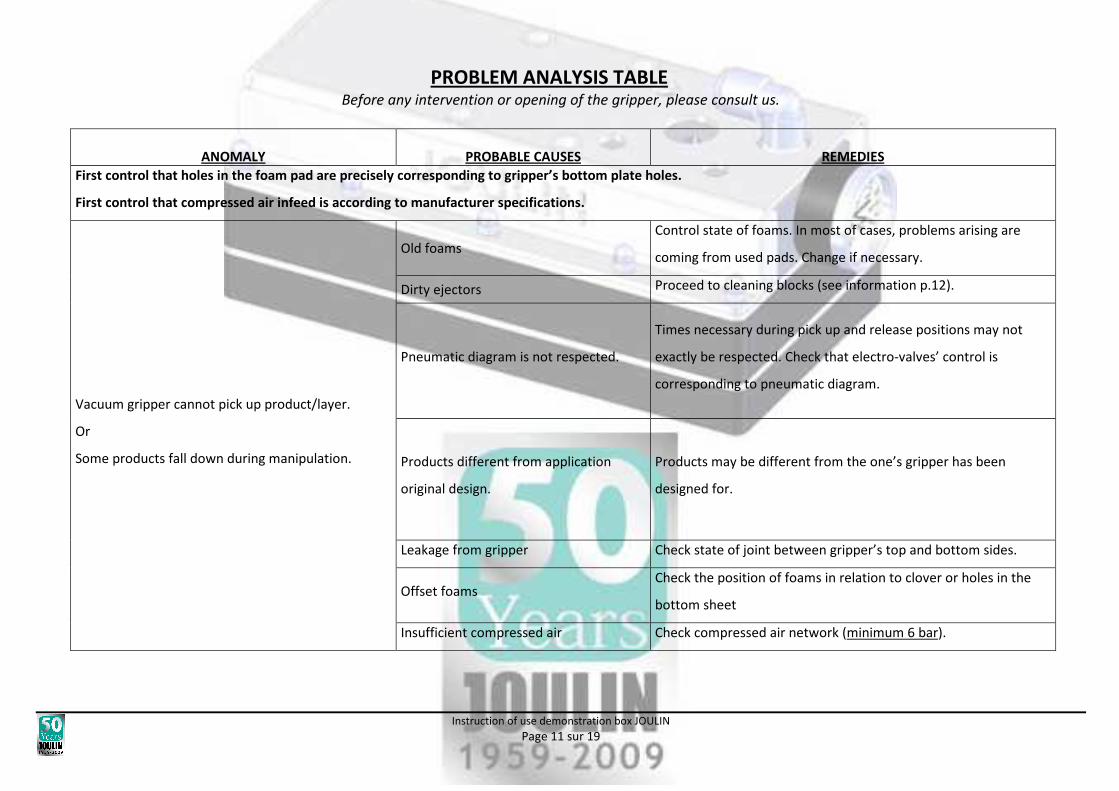
PROBLEM ANALYSIS TABLE Before any intervention or opening of the gripper, please consult us.
ANOMALY
PROBABLE CAUSES
REMEDIES
First control that holes in the foam pad are precisely corresponding to gripper’s bottom plate holes.
First control that compressed air infeed is according to manufacturer specifications.
Vacuum gripper cannot pick up product/layer.
Or
Some products fall down during manipulation.
Old foams
Control state of foams. In most of cases, problems arising are
coming from used pads. Change if necessary.
Dirty ejectors Proceed to cleaning blocks (see information p.12).
Pneumatic diagram is not respected.
Times necessary during pick up and release positions may not
exactly be respected. Check that electro-valves’ control is
corresponding to pneumatic diagram.
Products different from application
original design.
Products may be different from the one’s gripper has been
designed for.
Leakage from gripper Check state of joint between gripper’s top and bottom sides.
Offset foams Check the position of foams in relation to clover or holes in the
bottom sheet
Insufficient compressed air Check compressed air network (minimum 6 bar).

Instruction of use demonstration box JOULIN
Page 12 sur 19
CONTROLS
ELEMENTS
DAILY
WEEKLY
MONTHLY
ONCE A
YEAR
TYPE
OBSERVATIONS
MOUSSES X Visual If gripper is not working properly refer gripper’s
instruction of use
FILTRE ASPIRATION (OPTION) X Visual If gripper is not working properly refer gripper’s
instruction of use
VENTURI X
Refer to vacuum
generator instructions of
use
Replace air tightness joints if necessary

Instruction of use demonstration box JOULIN
Page 13 sur 19
DISASSEMBLY / CLEANING/ REASSEMBLY VENTURI BLOCKS
Unscrew the 4 hex screws from venturi block(s)
(BTR n°5)
Extract the block(s) of housing, taking care to O-ring(s). Unscrew ejector(s) from
block(s).
Remove ejector(s) and socket(s) quiet. Dismantle fittings and
vacuum gauges.
Disassemble ejector(s) and
clean with soapy water with
the block(s).
Reassemble the ejector(s) paying attention to the alignment
of the different stage.

Instruction of use demonstration box JOULIN
Page 14 sur 19
Replace the ejector(s) in the
block(s)
Shake socket(s) on the
block(s) then silencer(s).
Put O-ring(s) in throat(s)
provided for this purpose. If it
seems damaged, proceed to
its (their) replacement.
Return the gripper and slide
block(s) to its (their) location.
Place the 4 hex screws.
Tighten. Put the fitting. Then the vacuum gauge.
Change the foam if necessary
and proceed to test the
gripper.

Instruction of use demonstration box JOULIN
Page 15 sur 19
V. FOAM PADS STORING AND STCKING
HOW TO REPLACE FOAM PADS
1) Pull out old foam.
2) Clean gripper’s bottom side with solvent (in case of food application, use food soap)
3) Pull out protection sheet from new pad.
4) Apply new pad on bottom side while taking care to make foam’s holes coinciding with gripper’s
holes.
If possible run manipulator just after changing foams in order to better stick the foams
FOAM STORING CONDITIONS
� Store foams in flat position and avoid folding it.
� Do not store foams in a place exposed to sunlight.
� Storing room average temperature should be about 20°C.

Instruction of use demonstration box JOULIN
Page 16 sur 19

Instruction of use demonstration box JOULIN
Page 17 sur 19
VI. VACUUM GENERATOR
EJECTOR SI32-2
Two-stage COAX® cartridge - MIDI - with small mounting dimension for limited
spaces :
• Large vacuum flow in relation to energy
consumption.
• Suitable for high-volume evacuation when
handling porous materials or if surface leakage is
present.
• Unit psi :
• Unit MPa :

Instruction of use demonstration box JOULIN
Page 18 sur 19
EJECTOR SI32-3
Two-stage COAX® cartridge - MIDI - with small mounting dimension for limited
spaces :
• Large vacuum flow in relation to energy
consumption.
• Suitable for high-volume evacuation when
handling porous materials or if surface leakage is
present.
• Unit psi :
• Unit Mpa :

Instruction of use demonstration box JOULIN
Page 19 sur 19
VII. CONVERSION TABLE
Pression/ pressure / Druck
Unités de départ Facteur de conversion Unités obtenues
Beginning units Conversion factor Resulting units
Multiplikation des
Zahlenwertes in der Einheit mit Umrechungsfaktor
ergibt Zahlenwert
der Einheit
Pa 0,01 mbar
hP 1 mbar
kPa 10 mbar
mm water column 0,098 mbar
m water column 98,07 mbar
at 980,7 mbar
inch water column 2,491 mbar
PSI Ipf/in² 68,948 mbar
mbar 100 Pa
mbar 10,2 mm water column
mbar 10,2 x 10^ -3 m water column
mbar 1,02 x 10^ -3 at
mbar 0,4016 inch water column
mbar 14,505 x 10^ -3 PSI Ipf/in²
Capacité de préhension / Suction capacity /
Ansaugvolumenstrom /
Unités
de départ
Facteur
de conversion
Unités
obtenues
Beginning units Conversion factor Resulting units
Multiplikation
des
Zahlenwertes in
der Einheit
mit
Umrechungsfaktor
ergibt Zahlenwert
der Einheit
l/min 0,06 m3/h
gal/min 0,227 m3/h
ft3/min 1,699 m3/h
m3/h 16,667 l/min
m3/h 4,403 gal/min
m3/h 0,588 ft3/min
Longueur / Length / Länge
Unités
de départ
Facteur
de conversion
Unités
obtenues
Beginning
units Conversion factor Resulting units
Multiplikation
des
Zahlenwertes
in der Einheit
mit
Umrechungsfaktor
ergibt Zahlenwert
der Einheit
in. 25,4 mm
in. 0,0254 m
ft 305 mm
ft 0,305 m
m 39,37 in.
m 3,28 f
Puissance / Power / Elektrische Leistung
Unités de
départ Facteur de conversion
Unités
obtenues
Beginning units Conversion factor Resulting
units
Multiplikation
des
Zahlenwertes in
der Einheit
mit
Umrechungsfaktor
ergibt
Zahlenwert
der Einheit
hp 0,746 kW
Btu/h 293,1 kW
kW 1,341 hp
kW 3,41 x 10^ -3 Btu/h
Masse / Mass / Gewicht
Unités de départ Facteur de conversion Unités obtenues
Beginning units Conversion factor Resulting units
Multiplikation
des Zahlenwertes
in der Einheit
mit Umrechungsfaktor
ergibt
Zahlenwert der
Einheit
lbm 0,454 Kg
Kg 2,205 lbm