
UT10-2S Instruction Manual Instruction... · 2016-05-10UT10-2S Instruction Manual

Instruction ManualFor the Digital Monitoring System
(Software version SMB SW-V07.01; MPB SW-V05.01 or higher)

SenTec Digital Monitoring SystemNoninvasive Vent i lat ion and Oxygenat ion Monitor ing
40.15030 PCO2
mmHg
87140
50PRbpm
99100
85%SpO2
0.9 PI
°C42.0
00:0775
40.8
25
100
99
25
2011-02-10 14:36:307.8h100%+–
AD
B
-0.7
10
+0.4
B
+0
10
+0
0 min-15 min
0 min-15 min
RHP10


1 Trend Display Area2 Numerical Display Area3 Menu/Previous Level Button4 AUDIO PAUSED/OFF Button5 AUDIO PAUSED/OFF Indicator (yellow LED)6 Door Handle7 Docking Station Door8 Enter Button9 Display Button10 AC Power/Battery Indicator (green/yellow LED)11 UP/DOWN Buttons12 ON/OFF Indicator (green LED)13 Status Bar14 Speaker (on the side)
15 Sensor Connection Port16 Multipurpose l/O-Port (Nurse Call & Analog Output)17 Serial Data Port (RS-232)18 Network Port (LAN)19 Gas Bottle Slot20 Fan21 Equipotential Terminal Connector (ground)22 Fuse Holder23 AC Power Connector24 ON/OFF Switch
40.15030 PCO2
mmHg
8614050
PRbpm
99100
85%SpO2
1.0 PI
°C42.0
0 min
00:0675
40.8
25-15 min
2011-02-10 14:38:347.8h100%+–
AD
10
B
-0.7
-0.7
1 2 3 4
5
6
7
8101213
14
11 9
[Joe Miller]RHP10
19 20 21 22 23 24
15 16 17 18

WarrantyThe manufacturer warrants to the initial purchaser that each new component of the SenTec Digital Monitoring System (see list of components) will be free from defects in workmanship and materials. The manufacturer’s sole obligation under this warranty is to replace any component – for which the manufacturer acknowledges the warranty cover – with a replacement component.
Warranty Exclusions and System PerformanceSenTec AG can neither guarantee or verify instrument performance characteristics nor accept warranty claims or product liability claims if the recommended procedures are not carried out, if the product has been subject to misuse, neglect or accident, if the product has been damaged by extraneous causes, if accessories other than those recommended by SenTec AG are used, if the seal on the lower side of the monitor is broken, or if instrument repairs are not carried out by SenTec authorized service personnel.
CAUTION: Federal law (U.S.) restricts this device to sale by or on the order of a physician.
Patents/Trademarks/CopyrightInternational Industrial Design No. DM/054179, Japanese Design No. 1137696, U.S. Design Patent No. D483488. Canadian Patent No. 2466105, European Patent No. 1335666, German Patent No. 50111822.5-08, Spanish Patent No. 2278818, Hongkong Patent No. HK1059553, U.S. Patent No. 6760610. Chinese Patent No. ZL02829715.6, European Patent No. 1535055, German Patent No. 50213115.2, Spanish Patent No. 2316584, Indian Patent No. 201300, Japanese Patent No. 4344691, U.S. Patent No. 7862698. SenTec™, V-Sign™, V-STATS™, V-CareNeT™, V-Check™, Staysite™ and Advancing Noninvasive Patient Monitoring™ are trademarks of SenTec AG / © 2013 SenTec AG. All rights reserved. The contents of this document may not be reproduced in any form or communicated to any third party without the prior written consent of SenTec AG. While every effort is made to ensure the correctness of the information provided in this document, SenTec AG assumes no responsibility for errors or omissions. This document is subject to change without notice.
Patient MonitorWITH RESPECT TO ELECTRICAL SHOCK, FIRE AND MECHANICAL HAZARDS ONLY IN ACCORDANCE WITH UL 60601-1/CAN/CSA C22.2 No. 601.1, IEC 60601-1-4, IEC 60601-2-2320LW
SenTec AG, Ringstrasse 39, CH-4106 Therwil, Switzerland, www.sentec.ch
CLASSIFIED
ULC USR

Page 3 . Contents
ContentsIntended Use and Limitations ..................................................................................................... 5
Intended Use of the SenTec Digital Monitoring System (SDMS) ......................................................................................5Limitations of Transcutaneous PCO2 .................................................................................................................................6Limitations of Pulse Oximetry ...........................................................................................................................................6
The SenTec Digital Monitoring System (SDMS) .......................................................................... 7
Setting up the SenTec Digital Monitor (SDM) ............................................................................. 8Connect SDM to AC Power ...............................................................................................................................................8Battery Operation of the SDM ..........................................................................................................................................8Turning on the SDM ..........................................................................................................................................................8
Setting up the SDMS with a V-Sign™ Sensor .............................................................................. 9Installation of the Service Gas Bottle ...............................................................................................................................9Connection/Disconnection of Digital Sensor Adapter Cable .............................................................................................9Connect V-Sign™ Sensor ................................................................................................................................................ 10Check the V-Sign™ Sensor ............................................................................................................................................. 10V-SignTM Sensor Calibration and Storage ........................................................................................................................ 10V-SignTM Sensor Membrane Change ............................................................................................................................... 12
Setting up the SDMS with the SpO2 Soft Sensor ....................................................................... 14Connection/Disconnection of SpO2 Adapter Cable to SDM ............................................................................................. 14Connect SpO2 Soft Sensor to SpO2 Adapter Cable .......................................................................................................... 14
Measurement Sites and Sensor Application .............................................................................. 15Adult/Pediatric Patients (> 1 month of age) .................................................................................................................. 15Neonates (up to 1 month of age) ................................................................................................................................... 15

Monitoring with the SDMS ........................................................................................................ 16Measurement Settings .................................................................................................................................................... 16V-SignTM Sensor Attachment with the Ear Clip ................................................................................................................ 18V-SignTM Sensor Attachment with Multi-Site Attachment Rings ...................................................................................... 19Application of the Staysite™ Adhesive ........................................................................................................................... 21Monitoring with the V-Sign™ Sensor .............................................................................................................................. 23Removal of the V-Sign™ Sensor from Measurement Site ............................................................................................... 24Attachment of the SpO2 Soft Sensor .............................................................................................................................. 25Monitoring with the SpO2 Soft Sensor ............................................................................................................................ 25
Controls and Alarms of the SDM ............................................................................................... 26Buttons ........................................................................................................................................................................... 26LED Indicators ................................................................................................................................................................ 28Alarms ............................................................................................................................................................................ 28Status Bar ....................................................................................................................................................................... 29
Maintenance of the SDMS ......................................................................................................... 30Routine Checks ............................................................................................................................................................... 30Service ............................................................................................................................................................................ 30

Page 5 . Intended Use and Limitations
Intended Use of the SenTec Digital Monitoring System (SDMS) • The SenTec Digital Monitoring System – consisting of the SenTec Digital Monitor, sensors and accessories – is indicated for continuous, noninvasive patient monitoring. • V-Sign™ Sensor (VS-A/P) and V-Sign™ Sensor 2 (VS-A/P/N,)are indicated for use with the SenTec Digital Monitor when continuous, non-invasive monitoring of carbon dioxide tension (tcPCO2), oxygen saturation (SpO2), and pulse rate (PR) are required for adult and pediatric patients. In neonatal patients the use of V-Sign™ Sensor and V-Sign™ Sensor 2 is indicated for carbon dioxide tension monitoring only. • SenTec’s Ear Clip is intended for use with the V-Sign™ Sensor or V-Sign™ Sensor 2 when continuous, noninvasive carbon dioxide tension, oxygen saturation and pulse rate monitoring are required. The Ear Clip is for single-patient use and is indicated to attach the V-Sign™ Sensor or V-Sign™ Sensor 2 to the earlobe of the patient. The use of the Ear Clip is contraindicated for patients whose earlobes are too small to ensure adequate sensor application. • SenTec’s Multi-Site Attachment Rings MAR-SF and MAR-MI, are intended to attach V-Sign™ Sensor or V-Sign™ Sensor 2 to conventional measurement sites for carbon dioxide tension monitoring when continuous, non-invasive carbon dioxide tension monitoring is required for adult, pediatric, and neonatal patients. They are intended to attach V-Sign™ Sensor 2 to the forehead or cheek when continuous,
Intended Use and Limitationsnoninvasive carbon dioxide tension, oxygen saturation, and pulse rate monitoring is required for adult and pediatric patients. The Multi-Site Attachment Rings, MAR-SF and MAR-MI, are for single use. • SenTec’s Staysite™ Adhesive, model SA-MAR, is an optional, single-use adhesive which is indicated for use with the Multi-Site Attachment Rings, models MAR-MI and MAR-SF, if more secure attachment is required. • SenTec’s multi-compatible and reusable SpO2 Soft Sensors, models RSS-L, RSS-M, and RSS-S, are indicated for use with the monitoring devices indicated in the respective sensor directions for use when continuous non-invasive monitoring of oxygen saturation, and pulse rate are required for patients weighing more than 20kg /44lbs. • The SenTec Digital Monitoring System is indicated for use in hospitals, hospital-type facilities, intra-hospital transport environments, and – if under clinical supervision – home environments. • The SenTec Digital Monitoring System is for prescription use only.
Note: Hospital use typically covers areas such as general care floors, operating rooms, sleep labs, special procedure areas, intensive and critical care areas. Hospital-type facilities typically cover facilities such as surgical centers, special nursing facilities, and sleep labs outside of the hospital. Intra-hospital transport includes transport of a patient within the hospital or hospital-type facilities.

Limitations of Transcutaneous PCO2 The SDMS displays transcutaneous CO2 partial pressure (tcPCO2). The following clinical situations or factors may affect the correlation between tcPCO2 and arterial CO2 partial pressure (PaCO2) values: • hypoperfused measurement site due to low cardiac index, shock, circulatory centralization, hypothermia, vasoactive drugs, or mechanical pressure on measurement site (tcPCO2 readings are typically too high if the measurement site is hypoperfused) • inadequate measurement site and/or condition of patient’s skin and subcutaneous tissue (placement over large superficial veins or areas of skin breakdown or edema) • inadequate contact between sensor and patient’s skin causing the CO2 to diffuse out of the skin and intermix with ambient air • arterio-venous shunts
Note: The SDMS is not a blood gas device. Keep the above mentioned limitations in mind when interpreting tcPCO2 values.Note: When comparing tcPCO2 values displayed by the SDM to PaCO2 values obtained from arterial blood gas (ABG) analysis, please observe the following guidelines:1) Blood samples should be carefully drawn and handled in accordance with your institution’s guidelines. 2) Blood sampling should be performed in steady state conditions. 3) The PaCO2 value obtained from ABG analysis must be compared to the SDM’s tcPCO2 at the time of blood sampling. 4) The tcPCO2 values displayed by the SDM are automatically corrected to 37 °C (regardless of the patient’s core temperature, if “Severinghaus Correction Mode” = Auto). When performing the ABG analysis,
be sure to properly enter the patient’s core temperature into the blood gas analyzer. Use the blood gas analyzer’s 37 °C - PaCO2 value to compare with the SDM’s tcPCO2 values. 5) Verify proper operation of the blood gas analyzer. Periodically compare the blood gas analyzer’s barometric pressure against a known calibrated reference barometer.Note: Contact SenTec for correction factors to correct for other temperatures.
Limitations of Pulse OximetryThe SDMS monitors functional oxygen saturation (SpO2). The following clinical situations or factors may limit the correlation between SpO2 and arterial oxygen saturation (SaO2) values and may cause the loss of the pulse signal:1) dysfunctional hemoglobin values (COHb, MetHb), 2) intravascular dyes such as indocyanine green or methylene blue, 3) low perfusion at the measuring site, 4) skin pigmentation, 5) externally applied coloring agents (nail polish, dye, pigmented cream), 6) venous pulsations (e.g. patient in steep Trendelenburg position in combination with head measurement sites, some cardiocascular pathologies), 7) prolonged and/or excessive patient movement, 8) anemia, 9) exposure of the sensor to high ambient light levels, 10) defibrillation, and 11) some cardiovascular pathologies.Note: Oxygen saturation measurement techniques – including pulse oximetry – are not able to detect hyperoxemia.Note: Due to the S-shape of the oxyhemoglobin dissociation curve (ODC), pulse oximetry alone cannot reliably detect respiratory problems in patients being administered with supplemental oxygen.

Page 7 . The SenTec Digital Monitoring System (SDMS)
The SenTec Digital Monitoring System (SDMS)Note: Unless otherwise noted, the term “V-Sign™ Sensor” in the following refers to both V-Sign™ Sensor models: V-Sign™ Sensor and V-Sign™ Sensor 2.
The SenTec Digital Monitoring System (SDMS) consists of the following main components:
• SenTec Digital Monitor (SDM) including power cord (connector varies depending on country of sale) • SDMS Instruction Manual (language depending on country of sale) • SDMS Manual CD (provides detailed information on all system components, e.g., SDM Technical Manual, Directions for Use for Sensors and Disposables, etc.) • V-Sign™ Sensor (tcPCO2 / oximetry sensor) • Digital Sensor Adapter Cable (connects V-Sign™ Sensor to SDM) • SpO2 Soft Sensor (reusable oximetry sensor) • SpO2 Adapter Cable (connects SpO2 Soft Sensor to SDM) • V-Sign™ Membrane Changer (to change membrane and electrolyte of V-Sign™ Sensor) • Ear Clip, Multi-Site Attachment Rings and Staysite™ Adhesive (for V-Sign™ Sensor application) • Contact Gel (contact liquid for V-Sign™ Sensor) • Service Gas (gas for V-Sign™ Sensor calibration) • V-STATS™ Installation CD
Additional instructions for the SenTec Digital Monitor, the V-Sign™ Sensor, the SpO2 Soft Sensor, the V-Sign™ Membrane Changer, the Ear Clip and the Multi-Site Attachment Rings are provided in the respective Directions for Use. To ensure proper operation of the SDMS, precisely follow the instructions provided in this Instruction Manual step by step.
WARNING: The instructions given in the SDMS Quick Reference Guide, the SDMS Instruction Manual, the SDM Technical Manual and the Manual CD for the SenTec Digital Monitoring System must be followed in order to ensure proper instrument performance and to avoid electrical hazards.
Note: The components listed above do not necessarily correspond to the scope of delivery. A complete list of available products including disposables and accessories is provided on the SenTec Website (www.sentec.ch).

Connect SDM to AC PowerPlug the female connector of the power cord into the AC power connector on the rear of the monitor 23 .Plug the male connector of the power cord into a properly grounded AC power outlet.The SDM will automatically adapt to the applicable local voltage: 100 - 240V~ (50/60Hz).
Verify that the AC power/battery indicator 10 is lit. If the AC power/battery indicator is not lit, check the power cord, fuses, and the AC power outlet.
Battery Operation of the SDMThe SDM is equipped with a rechargeable internal Li-Ion battery that can be used to power the monitor during transport or when AC power is not available. A new, fully charged battery will provide 11 hours of monitoring time (if Sleep mode=OFF, Auto) and 16 hours of monitoring time (if Sleep mode=ON), respectively (display with LED backlight). The battery icon ( 75%
+-) indicates the remaining battery charge (%).
The AC Power/Battery Indicator 10 provides information on the charging status of the battery:green: SDM connected to AC power, battery fully chargedyellow: SDM connected to AC power, battery charging LED off: SDM not connected to AC power (i.e. powered by internal battery)It takes approximately 7 hours to fully charge a drained battery.
Turning on the SDMTurn on the SDM by pushing the ON/OFF switch on the back panel 24 . The SDM will automatically perform a power-on self-test (POST). Note: If the POST fails, discontinue use of the SDM and contact SenTec authorized service personnel or your local SenTec representative (refer to the SDM Technical Manual).Check the following settings and make adjustments if necessary: 1) the current profile, 2) the selected patient mode (Adult/Neonatal), 3) the temperature settings, and 4) the available monitoring time of the SDM.
Setting up the SenTec Digital Monitor (SDM)
ON/OFF switch

Page 9 . Setting up the SDMS with a V-Sign™ Sensor
Setting up the SDMS with a V-Sign™ SensorInstallation of the Service Gas BottleNote: The calibration gas is only required for tcPCO2 monitoring with V-Sign™ Sensor.Note: Dispose of empty gas bottles according to local waste disposal regulations for aluminum containers.Note: The status icon “Gas” ( 100% ) is displayed only if the sensor is in the Docking Station and if the parameter “tcPCO2” is enabled. The “Gas” icon will be yellow if the remaining capacity is below 10% and red if the gas bottle is empty. Replace the gas bottle if the message ‘Gas bottle empty’ ( 0% ) is displayed in the status bar.The gas bottle slot is located on the rear of the SDM 19 .
Remove the gas bottle by turning it counter-clockwise. Insert the gas bottle by turning it clockwise and tighten it without applying undue force.
Note: Do not use expired gas bottles.
WARNING: Ensure that the gas bottle is fully inserted by turning it clockwise approx. 4.5 turns and tighten it without applying undue force. Failure to properly insert the gas bottle may result in incorrect sensor calibration and may cause in-creased gas consumption.
WARNING: The Service Gas bottle is a pressurized container. Protect from sunlight and do not expose to temperatures exceeding 50°C (122°F). Do not pierce or burn, even after use. Do not spray on a naked flame or any incandescent material.
WARNING: Do not use expired gas bottles or gas bottles from manufacturers other than SenTec. The use of non-SenTec gas bottles may damage the Docking Station. Improper calibration gas mixtures will result in incorrect sensor calibrations and subsequently result in incorrect tcPCO2 data.
Connection/Disconnection of Digital Sensor Adapter CableConnect the Digital Sensor Adapter Cable to the SDM. The connection is properly established when both clamps of the plug snap into place in the socket 15 .
Disconnect the cable from the SDM by pressing the two latches on the black plug to release the clamps (see picture) and pull to remove the cable.

Connect V-Sign™ SensorConnect the V-Sign™ Sensor to the Digital Sensor Adapter Cable.
Check the V-Sign™ Sensora) Clean any residue on the sensor by carefully wiping the surface (including membrane, housing and cable) with 70% isopropanol.Note: Do not use the sensor if there is any visible damage to the sensor housing or cable or if the color of the ring around the glass in the center of the sensor has a metallic
luster (should be brown). Contact SenTec authorized service personnel or your local SenTec representative.b) Change the sensor membrane if it is damaged, does not have a tight fit, or if there is trapped air or dry electrolyte under the membrane.
V-Sign™ Sensor Calibration and StorageIf a sensor calibration is required, the SDM will display the message ‘Calibrate sensor’ in the status bar. The message ‘Sensor calibration recommended’ is displayed if calibration of the sensor is recommended.
To calibrate the sensor:1. Open the Docking Station door by pulling the door handle.
2. Check the gasket in the Docking Station. If necessary, clean Docking Station and gasket by using a cotton swab moistened with 70% isopropanol.
WARNING: Always clean the sensor before placing it in the Docking Station.
3. Hang the sensor in the holder in the inside of the door (the red light will be visible).

Page 11 . Setting up the SDMS with a V-Sign™ Sensor
Note: After switching on the monitor or after a membrane change, store the sensor in the Docking Station for at least for the duration indicated by the yellow information message ‘Recommended Sensor Stabilization [min]:’ on the “Ready for use” screen and on the “Calibration” screen.
WARNING: To maintain monitor readiness in between monitoring uses, keep the monitor switched on and always store the V-SignTM Sensor in the Docking Station while the sensor is connected to the SDM.
The SDM provides a SMART CALMEM function that allows a calibrated V-Sign™ Sensor to be disconnected and reconnected without the need for recalibration, provided that the duration of the disconnection is less than 30 minutes and that the “Calibration Interval” does not elapse while the sensor is disconnected.
Note: No calibration will be initiated if a calibrated sensor is removed from the Docking Station and re-inserted into the Docking Station within 10 minutes.
Note: Manual calibration can be activated via a “Quick Access Menu” (refer to the “Buttons” section on p. 26).
CAUTION: Incorrect orientation of the sensor in the Docking Station may cause damage to the sensor, the Docking Station, or parts of thereof.
4. The sensor must be placed correctly in the holder in order for the Docking Station door to be closed properly.
WARNING: For calibration to be performed correctly, the sensor must be positioned correctly in the Docking Station door and the Docking Station door must be properly closed.
5. Properly close the Docking Station door. The SDM will then check the sensor and automatically start the calibration if necessary. If the sensor is ready for use, a message will be displayed accordingly. If a sensor mem-brane change is required, follow the instructions provided on the following pages then confirm the membrane change as instructed by the monitor.

V-Sign™ Sensor Membrane ChangeIf the “Membrane Change Interval” has elapsed, the SDM displays the message ‘Change sensor membrane’, triggers a low priority alarm, activates the menu ‘Membrane Change’ and marks tcPCO2 as invalid. Additionally, the membrane must be changed if any of the previously described conditions exist (see “Check the V-SignTM Sensor” section on p. 10).
The sensor membrane of the V-Sign™ Sensor must be changed using the V-Sign™ Membrane Changer.
Insert sensor into membrane changer
1. Place the V-Sign™ Membrane Changer on a solid flat surface such as a table top.
2. Hold the sensor head horizontally (membrane up) and insert it into the V-Sign™ Membrane Changer.
Note: Do not touch or hold the sensor cable while the sensor is inside in the membrane changer, as this may dislodge the sensor from the membrane changer.
Four steps to change sensor membrane
The membrane change procedure consists of the following four steps: 1) remove old sensor membrane, 2) clean sensor surface, 3) apply new electrolyte on sensor surface and 4) place new membrane on sensor.
Keep the Membrane Changer horizontal while repeating the following procedure 4 ti mes:
1. Press down slowly but firmly with palm of hand and hold for 3 seconds.
2. Hold the base of the membrane changer with one hand and turn top clockwise with the other hand to the next stop.
Repeat this process 3 additional times.
Important: Be sure to perform the Press and Turn procedure 4 times!
1x
1x
1x press3 sec.

Page 13 . Setting up the SDMS with a V-Sign™ Sensor
Remove sensor from membrane changer
Press once again or lift the sensor to release and remove it from the V-Sign™ Membrane Changer.
Inspect sensor membrane
WARNING: Do not use the sensor if the color of the ring around the glass in the center of the sensor has a metallic luster.
1. Verify that the membrane ring is securely seated on the sensor.
2. Verify that there are no air bubbles between the membrane and the surface of the sensor.
If the membrane does not have a tight fit, if there is trapped air or if the membrane is damaged, you must repeat the membrane change procedure as described above.
Confirm Membrane Change on SDM
If sensor check / inspection of sensor membrane has been completed successfully, confirm the membrane change on the monitor (menu ‘Membrane Change’).
Note: The membrane timer only resets if you confirm the membrane change on the monitor.
Note: The menu ‘Membrane Change’ is only accessible if the Docking Station door is open.
Important: The Contact Gel is not needed in any step of the remembraning process. The Contact Gel is only used for sensor application.

Setting up the SDMS with the SpO2 Soft SensorConnection/Disconnection of SpO2 Adapter Cable to SDM
Connect the SpO2 Adapter Cable to the SDM. The connection is properly established when both clamps of the plug snap in place in the socket 15 . Disconnect the cable from the SDM by pressing the two latches on the black plug to release the clamps (see picture) and pull to remove the cable.
Connect SpO2 Soft Sensor to SpO2 Adapter Cable Open the plastic latch at the end of the SpO2 Adapter Cable and plug the sensor in the SpO2 Adapter Cable. Snap the plastic latch over the sensor connector.
1.
2.

Page 15 . Measurement Sites and Sensor Application
Measurement Sites and Sensor Application V-Sign™ Sensor 2 (VS-A/P/N) and SpO2 Soft Sensor (RSS-M)
Adult / Pediatric Patients (> 1 month of age) Neonates (up to 1 month of age)
Parameter Measurement Site Skin Condition Application Accessory Parameter Measurement Site Skin Condition Application Accessory
tcPCO2, SpO2/PR
Earlobe intact Ear Clip
tcPCO2
Thorax under clavicle, abdomen, back, low on forehead, inner or anterior aspect of the thigh
mature, intact
MAR-MI Low on forehead, cheek
intact MAR-MIsensitive, fragile
MAR-SF sensitive, fragile
MAR-SF
tcPCO2
Earlobe intact Ear Clip
Low on forehead, cheek, thorax under clavicle, upper arm, area behind earlobe
intact MAR-MI sensitive, fragile
MAR-SF
SpO2/PR
Earlobe intact Ear ClipLow on forehead, cheek
intact MAR-MIsensitive, fragile
MAR-SF
Finger, toes (patient >20kg)
intact SpO2 Soft Sensor
The choice of the sensor and the type of sensor application depends on the parameters to be measured, the skin condition, and the patient´s age.
Note: To attach a V-Sign™ Sensor with the Ear Clip, the earlobe needs to be large enough to cover the entire sensor membrane. If the earlobe is too small, use a Multi-Site Attachment Ring (model MAR-MI or MAR-SF) to attach the sensor to an alternate site. Pierced earlobes may result in incorrect tcPCO2 measurements.Note: For V-Sign™ Sensor VS-A/P (grey cable), SpO2/PR monitoring is only approved for use on earlobes of adult/pediatric patients.
WARNING: In order to avoid erroneous readings and false SpO2 and PR alarms, verify that the appropriate patient mode (Adult) is selected and that SpO2/PR parameters are disabled in the menu of the SDM if these parameters are not approved for the selected measurement site.

Measurement SettingsIf the SDMS is ready for use, the message ‘Ready for use’ will be displayed in large yellow letters in the center of the screen. Before you start monitoring, verify: 1) the current profile, 2) the selected patient mode (Adult/Neonatal), 3) the temperature settings, and 4) the available monitoring time on the “Ready for use” screen. Also check the alarm limits, trend graph ranges for the enabled parameters, as well as the time range for trends. Make any necessary adjustments.
“Ready for use” screen
Ready for useEnabled Parameters PCO2 SPO2 PRAvailable Monitoring Time [hrs]: 12.0Membrane Change is Due in [days]: 42.0
AdultVS-A/P/NSLEEP
°C
SET T[°C] = 42.0Joe Miller
The following information is displayed in the upper left corner of the screen:
Patient type indicator (yellow): Displays the current patient type (Neonatal or Adult).
Customized Info (orange): Optional display of patient information during V-CareNeT™ remote monitoring. Note: The ‘Customized Info’ is only displayed if the SDM is connected to V-CareNeT™ and if display of the ‘Customized Info’ on the SDM is enabled in the dialog window ‘V-CareNet™ settings’.
Sensor type indicator: Displays the model/type of the currently connected sensor.
Current profile indicator: In ‘Institutional Mode’ this indicator displays the name of the currently selected / activated profile (e.g. ‘SLEEP’). An asterisk (‘*’) is added after the profile name (e.g. ‘SLEEP*’) if at least one parameter in the selected profile has been modified. In ‘Basic Mode’ the profile indicator is not displayed. For detailed information about profiles, please refer to the SDM Technical Manual.
Note: In ‘Institutional Mode’ you may customize SDM profiles to the specific needs of different clinical settings, store up to four profiles in the SDM and change profiles in the ‘profile’ screen. Various preconfigured profiles are available in a password protected area of V-STATS™.
Information displayed in the upper right corner:Sensor SET Temperature: Displays the currently selected Sensor SET Temperature (this indicator only displays if the connected sensor is heated).
Monitoring with the SDMS
Page 17 . Monitoring with the SDMS
WARNING: A Sensor SET Temperature should be set no higher than 41.5 °C for neonates / infants (up to one year of age).
WARNING: The use of temperatures higher than 41°C requires special attention to patients with susceptible skin, e.g. neonates, geriatric patients, burn victims, patients with skin diseases.
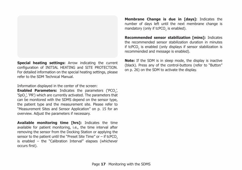
Special heating settings: Arrow indicating the current configuration of INITIAL HEATING and SITE PROTECTION. For detailed information on the special heating settings, please refer to the SDM Technical Manual.
Information displayed in the center of the screen:Enabled Parameters: Indicates the parameters (‘PCO2’, ‘SpO2’, ‘PR’) which are currently activated. The parameters that can be monitored with the SDMS depend on the sensor type, the patient type and the measurement site. Please refer to “Measurement Sites and Sensor Application” on p. 15 for an overview. Adjust the parameters if necessary.
Available monitoring time [hrs]: Indicates the time available for patient monitoring, i.e., the time interval after removing the sensor from the Docking Station or applying the sensor to the patient until the “Preset Site Time” or – if tcPCO2 is enabled – the “Calibration Interval” elapses (whichever occurs first).
Membrane Change is due in [days]: Indicates the number of days left until the next membrane change is mandatory (only if tcPCO2 is enabled).
Recommended sensor stabilization [mins]: Indicates the recommended sensor stabilization duration in minutes if tcPCO2 is enabled (only displays if sensor stabilization is recommended and message is enabled).
Note: If the SDM is in sleep mode, the display is inactive (black). Press any of the control-buttons (refer to “Button” on p. 26) on the SDM to activate the display.
V-Sign™ Sensor Attachment with the Ear Clip
WARNING: Application of any pressure to the measurement site (e.g. by using a pressure bandage) may cause pressure ischemia at the measurement site and, consequently, inaccurate measurements, necrosis or - in combination with heated sensors - burns.
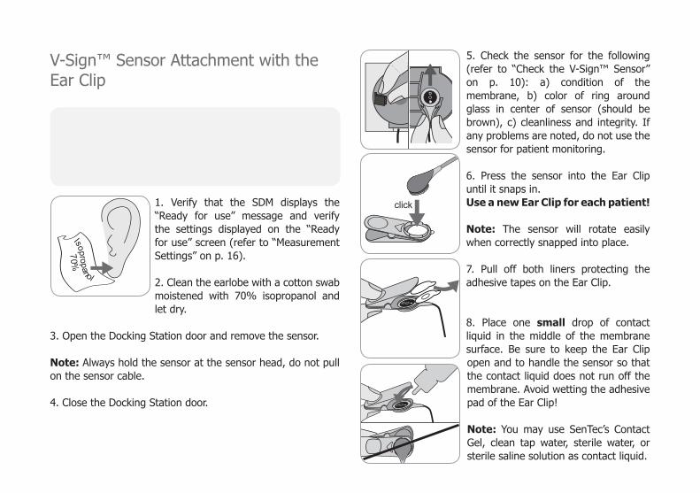
1. Verify that the SDM displays the “Ready for use” message and verify the settings displayed on the “Ready for use” screen (refer to “Measurement Settings” on p. 16).
2. Clean the earlobe with a cotton swab moistened with 70% isopropanol and let dry.
3. Open the Docking Station door and remove the sensor.
Note: Always hold the sensor at the sensor head, do not pull on the sensor cable.
4. Close the Docking Station door.
5. Check the sensor for the following (refer to “Check the V-Sign™ Sensor” on p. 10): a) condition of the membrane, b) color of ring around glass in center of sensor (should be brown), c) cleanliness and integrity. If any problems are noted, do not use the sensor for patient monitoring.
6. Press the sensor into the Ear Clip until it snaps in.Use a new Ear Clip for each patient!
Note: The sensor will rotate easily when correctly snapped into place.
7. Pull off both liners protecting the adhesive tapes on the Ear Clip.
8. Place one small drop of contact liquid in the middle of the membrane surface. Be sure to keep the Ear Clip open and to handle the sensor so that the contact liquid does not run off the membrane. Avoid wetting the adhesive pad of the Ear Clip!
Note: You may use SenTec’s Contact Gel, clean tap water, sterile water, or sterile saline solution as contact liquid.
click
Isopropanol
70%

Page 19 . Monitoring with the SDMS
WARNING: Do not swallow Contact Gel. Keep away from children. Avoid contact with eyes and injured skin. Use only approved SenTec Contact Gel.
9. Pull earlobe horizontally. Move the sensor horizontally into place and attach to the back of the earlobe. Close clip from above then guide earlobe back to a vertical position. The sensor is applied correctly if its entire dark surface is covered by the earlobe. Ensure that air gaps are eliminated between the skin and the sensor.
10. Wrap the sensor cable around the ear once and tape the cable to the cheek as shown in the picture. Gently squeeze the sensor and Ear Clip as a final application check. Secure the cable with the Clothing Clip to the patient’s clothing or a bed linen.
11. Verify that tcPCO2 is rising (tcPCo2 stabilization - refer to “Monitoring with the V-Sign™ Sensor” on p. 16 and confirm that the readings for SpO2 and PR, if enabled, are stable. If necessary, verify sensor application or reposition the sensor.
Note: Always apply sensor on intact and closed skin sites. Pierced earlobes may result in incorrect tcPCO2 measurements.
V-Sign™ Sensor Attachment with Multi-Site Attachment Rings
WARNING: Application of any pressure to the measurement site (e.g. by using a pressure bandage) may cause pressure ischemia at the measurement site and, consequently, inaccurate measurements, necrosis or - in combination with heated sensors - burns.
1. Verify that the SDM displays the “Ready for use” message and verify the settings displayed on the “Ready for use” screen (refer to “Measurement Settings” on p. 16).
2. Select the appropriate attachment ring (MAR-MI or MAR-SF) and measurement site (refer to “Measurement Sites and Sensor Application” on p. 15).
Note: Avoid placing the sensor on large superficial veins or areas of skin breakdown.
3. Remove hair from the measurement site if necessary.
4. Clean the skin at the measuring site with a cotton swab moistened with 70% isopropanol and let dry.
Use a new attachment ring for each new application and patient!
5. Pull off the liner protecting the adhesive tape on the attachment ring.

6. Attach the ring to the measurement site and press gently on the snap ring. Gently slide your finger around the circumference of the ring to ensure a good seal and that the entire surface is adhered to the skin.
7. Apply one small drop of contact liq-uid to the skin area in the center of the attachment ring. Alternatively you can use a cotton swab to apply the contact liquid. Ensure that the contact liquid does not wet the adhesive.
Note: You may use SenTec’s Contact Gel, clean tap water, sterile water, or sterile saline solution as contact liquid.
WARNING: Do not swallow Contact Gel. Keep away from children. Avoid contact with eyes and injured skin. Use only approved SenTec Contact Gel.
8. Open the Docking Station door and remove the sensor.
Note: Always hold the sensor at the sensor head, do not pull on the sensor cable.
9. Close the Docking Station door.
10. Check the sensor for the following (refer to “Check the V-Sign™ Sensor” on p. 10): a) condition of the membrane, b) color of ring around glass in center of sensor (should be brown), c) cleanliness and integrity. If any problems are noted, do not use sensor for patient monitoring.
11. Holding the sensor at the cable strain relief (light grey sensor case), approach the MAR from the flap side and insert the nose of the sensor into the ring. Then apply a slight downward pressure on the cable strain relief. The spring tension of the application device will pull the sen-sor into place with minimal pressure on
the skin. Twist the sensor in the ring and press the sensor gently against the skin to spread the contact liquid.
Note: Care must be taken to ensure that air gaps are elimi-nated between the skin and the sensor.

Page 21 . Monitoring with the SDMS
12. Twist the sensor into the best position. For forehead/cheek placement wrap the sensor cable once around the ear and tape the cable to the cheek. For other application sites, tape the cable at a distance of 5 to 10 cm from the sensor head to the skin. Secure it with a Clothing Clip to the patient’s clothing or a bed linen.
13. Verify that tcPCO2 is rising (tcPCO2 stabilization - refer to “Monitoring with the V-Sign™ Sensor” on p. 23) and confirm that the readings for SpO2 and PR, if enabled, are stable. If needed, verify sensor application or reposition the sensor.
Note: Alternatively, you may click the sensor into the Multi-Site Attachment Ring first and then attach the assembly to the skin.
Application of the StaysiteTM Adhesive
WARNING: Application of any pressure to the measurement site (e.g. by using a pressure bandage) may cause pressure ischemia at the measurement site and, consequently, inaccurate measurements, necrosis or - in combination with heated sensors - burns.
WARNING: Avoid applying Staysite™ Adhesive film completely circular around a limb.
CAUTION: Do not apply to injured skin.
CAUTION: SenTec’s Staysite™ Adhesive is not recommended for patients who exhibit allergic reactions to adhesive tape or for patients who perspire profusely.
Note: Use the Staysite™ Adhesive together with a Multi-SiteAttachment Ring and always apply the Multi-Site AttachmentRing prior to the application of a Staysite™ Adhesive.
Note: Always attach the MAR-compatible SenTec sensor afterthe application of the Staysite™ Adhesive.

Schematic view of the Staysite™ Adhesive film. Numbers 1 2 3 indicate the sequence of application.
1. Hold the Staysite™ Adhesive film at the site with the small backing paper 2 with one hand. Then, remove the
other large backing paper 1 with the other hand.
2. Apply the Staysite™ Adhesive film on top of the Multi-Site Attachment Ring to the skin. Take care to place the circular cut-out of the Staysite™ Adhesive exactly over the attachment ring of theMAR.
Use a new adhesive film for each new application!
3. Smooth down the adhesive film.
4. Remove the small backing paper 2 . Apply the film to the skin and smooth down.
5. Finally, remove the paper frame 3 on top of the Staysite™ Adhesive.
Smooth down the adhesive film. Check for smooth fit to skin and Multi-Site Attachment Ring.
To remove Staysite™ Adhesive, gently stretch the film parallel to the skin and pull off.Remove the Multi-Site Attachment Ring from the skin by carefully pulling at the little tab.
Note: Careful removal of adhesive tapes from the skin is important.
1
2
3
3

Page 23 . Monitoring with the SDMS
Monitoring with the V-Sign™ Sensor
After sensor application, tcPCO2 readings typically stabilize within 2 to 10 minutes, i.e., the time required to warm up and induce local arterialization of the measurement site as well as to achieve equilibrium between the CO2 concentration in the skin tissue and the CO2 concentration in the sensor’s electrolyte. During tcPCO2 stabilization, tcPCO2 values increase, the message ‘PCO2 stabilizing’ displays and tcPCO2 readings are marked as unstable (value displayed in grey), thereby indicating that tcPCO2 readings during tcPCO2 stabilization do not reflect patient’s tcPCO2 level. During tcPCO2 stabilization both visual and auditory alarms are suppressed for the tcPCO2 channel. If the measured values do not stabilize, check that the sensor has been applied correctly. In order to reduce the occurrence of air gaps/leaks between the sensor and the skin, a good contact between the sensor and the patient’s skin is essential. Make sure that the sensor cable is fixed on the skin such that the sensor cable is not stretched or pulled.
Depending on the selected patient type (menu-parameter ‘Measurement Settings/Patient’), and the selected parameters (menu-parameter ‘Measurement Settings/Enabled Parameters’) different preconfigured measurement screens are available.
Baselines for tcPCO2 and SpO2 (e.g. for easy recognition of measurement changes after changing ventilator settings or medications) can be set on the “Online Trend” screen. The screen displays difference information (delta) in relation to a specific delta time (minutes) in the past and to the set baselines (∆10 = difference between current value and value 10 minutes before, ∆B = difference between current and baseline value).
The SDM manages the maximum site time. Remove the sensor when the monitoring time has elapsed, either because the site time has elapsed (status message ‘Site time elapsed’) or because a calibration of the sensor is mandatory (status message ‘Calibrate sensor’).
40.15030 PCO2
mmHg
87140
50PRbpm
9910085
%SpO2
0.9 PI
°C42.0
00:0775
40.8
25
100
99
25
2011-02-10 14:36:307.8h100%+–
AD
B
-0.7
10
+0.4
B
+0
10
+0
0 min-15 min
0 min-15 min
RHP10
12 sec 0 sec
0 min
100
75
75
25-15 min
-15 min
0 min
2009-09-01 15:28:317.7h100%
+-
AD°C
41.9
39.4 4521 PCO2
mmHg
8416151 PR
bpm
96 10085 %SpO2
2.0 PI
Removal of the V-Sign™ Sensor from Measurement Site
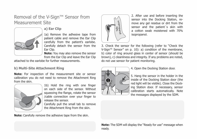
a) Ear Clip
1a) Remove the adhesive tape from patient cable and remove the Ear Clip care fully from the patient’s earlobe. Care fully detach the sensor from the Ear Clip.Note: You may also remove the sensor from the Ear Clip and leave the Ear Clip
attached to the earlobe for further measurements.
b) Multi-Site Attachment Ring
Note: For inspection of the measurement site or sensor calibration you do not need to remove the Attachment Ring from the skin.
1b) Hold the ring with one finger on each side of the sensor. Without squeez ing the flange, rotate the sensor /cable connection over your finger to release the sensor.Carefully pull the small tab to re move the Attachment Ring from the skin.
Note: Carefully remove the adhesive tape from the skin.
Important: Always inspect skin before re-applying the sensor to the same measurement site.
2. After use and before inserting the sensor into the Docking Station, re-move any gel residue or dirt from the sensor and the patient´s skin with a cotton swab moistened with 70% isopropanol.
3. Check the sensor for the following (refer to “Check the V-SignTM Sensor” on p. 10): a) condition of the membrane, b) color of ring around glass in center of sensor (should be brown), c) cleanliness and integrity. If any problems are noted, do not use sensor for patient monitoring.
4. Open the Docking Station door.
5. Hang the sensor in the holder in the inside of the Docking Station door (the red light will be visible). Close the Dock-ing Station door. If necessary, sensor calibration starts automatically. Note the messages displayed by the SDM.
WARNING: To maintain monitor readiness in between monitoring uses, always keep the monitor switched on and store the V-SignTM Sensor in the Docking Station while the sensor is connected to the SDM.
Note: The SDM will display the “Ready for use” message when ready.
isop
rop
ano
l
70%
sensorsensor

Page 25 . Monitoring with the SDMS
Attachement of the SpO2 Soft Sensor Select a suitable site for the SpO2 Soft sensor. The patient’s index finger is the preferred location. Alternative sites are the thumb, big toe and little finger.
Fit the sensor as illustrated in the SpO2 Soft Sensor’s Directions for Use. The patient’s finger must be fully inserted to the end of the sensor. Direct the cable along the patient‘s finger and parallel to the arm. Affix with adhesive tape if required.
Monitoring with the SpO2 Soft SensorAfter sensor application, SpO2 and PR readings typically stabilize within the first minute. During SpO2 and PR stabilization, SpO2 and PR readings are marked as unstable (value displayed in grey).
If the measured values do not stabilize, verify the sensor application. Make sure the sensor cable is fixed on the skin so that the cable is not stretched or pulled.
Different preconfigured measurement screens are available (for details refer to the SDM Technical Manual).
The maximum site time is managed by the SDM. Remove the sensor when the monitoring time has elapsed. (The status message ‘Site time elapsed’ will be displayed.)
Important: Always inspect the skin before re-applying the sensor to the same measurement site.
-15 min 0 min
0 min
100
50
125
30
12 sec
-15 min
0 sec
7310171 PR
bpm
8710090 %SpO2
3.9h100%+-
AD
2.0 PI
2009-09-01 15:28:31

Controls and Alarms of the SDM
ButtonsThe six control buttons on the SDM are used as follows:
Menu/Pre-vious Level Button
• to access the menu • to return to the menu on the next higher level (only if ‘editing mode’ is inactive) • to de-activate the ‘editing mode’ for the selected menu-parameter
Note: Menu-Access can be disabled/blocked (e.g. for home use)
+ and
–
UP & DOWN Button
• to navigate the blue menu bar up and down (only if ‘editing mode’ is inactive) • to increase or decrease the value of the menu parameter for which the ‘editing mode’ is active
Note: most changes become effective immediately without confirmation • to increase or decrease brightness of the display (only during patient monitoring)
AUDIO PAUSED/AUDIO OFF Button
• to pause auditory alarm signals for 1 or 2 minutes (depending on menu setting) • to switch OFF auditory alarm signals permanently (by pressing > 3 seconds)
Note: switching off auditory alarm signals is only possible if enabled by Responsible Organization (for details refer to the SDM Technical Manual)Note: This button is inactive if the menu parameter ‘Alarm Settings / Alarm Volume’ is set to OFF by the responsible organization.
Enter Button
• to activate Quick Access Menus (for details refer to the SDM Technical Manual) • to activate the selected sub-menu or function • to activate/deactivate ‘editing mode’ for the selected menu parameter • to confirm latched alarms (for details refer to the SDM Technical Manual) • to activate an additional screen of the ‘System Information’ providing hardware/software information of motherboard and docking station.
Page 27 . Controls and Alarms of the SDM
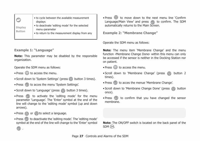
DisplayButton
• to cycle between the available measurement displays • to deactivate ‘editing mode’ for the selected menu-parameter • to return to the measurement display from any
Example 1: “Language”
Note: This parameter may be disabled by the responsible organization.
Operate the SDM menu as follows:
• Press to access the menu.
• Scroll down to ‘System Settings’ (press – button 3 times).
• Press to acces the menu ‘System Settings’.
• Scroll down to ‘Language’ (press – button 3 times).
• Press to activate the ‘editing mode’ for the menu parameter ‘Language’. The ‘Enter’ symbol at the end of the line will change to the ‘editing mode’ symbol (up and down arrows).
• Press + or – to select a language.
• Press to deactivate the ‘editing mode’. The ‘editing mode’ symbol at the end of the line will change to the ‘Enter’ symbol
.
• Press – to move down to the next menu line ‘Confirm Language/Main View’ and press to confirm. The SDM automatically returns to the Main Screen.
Example 2: “Membrane Change”
Operate the SDM menu as follows:
Note: The menu item ‘Membrane Change’ and the menu function ‹Membrane Change Done› within this menu can only be accessed if the sensor is neither in the Docking Station nor on patient.
• Press to access the menu.
• Scroll down to ‘Membrane Change’ (press – button 2 times).
• Press to acces the menue ‘Membrane Change’.
• Scroll down to ‘Membrane Change Done’ (press – button once).
• Press to confirm that you have changed the sensor membrane.
Important: The membrane timer will only reset if you confirm the membrane change.
Note: The ON/OFF switch is located on the back panel of the SDM 24 .

LED Indicators
The SDM uses three LEDs for visual indication of alarms, on/off status and power status:
AUDIO PAUSED/AUDIO OFFIndicator
• yellow: Auditory alarm signals paused for 1 or 2 minutes
• flashes yellow: Auditory alarm signals perma-nently switched off (by pressing ‘AUDIO PAUSED/ AUDIO OFF’ Button > 3 seconds)
• LED off: Auditory signals either active or perma-nently switched off by setting menu parameter ‘Alarm Settings / Alarm Volume’ to OFF
On/Off Indicator
• green: SDM turned on • LED off: SDM turned off
AC Power/Battery Indicator
• green: Connected to AC power, battery fully charged
• yellow: Connected to AC power, battery charging • LED off: Not connected to AC power (i.e. pow-ered by internal battery)
Note: The AC Power / Battery Indicator functions irrespective of the SDM being switched ON or OFF.
Alarms
The SDM uses auditory alarms (as described in this section) as well as visual alarms (refer to the previous and the following sections), to alert the user when a measurement value is outside alarm limits and to inform the user about technical conditions of the equipment that require operator response or awareness.
Note: For a detailed description of alarm melodies, which can be switched on by the responsible organization, please refer to the SDM Technical Manual.
The following auditory alarms are provided:
High priority alarm:A high-pitched fast pulsing tone indicating a SpO2 value is outside the limits (two bursts of five short pulses repeated every 10 seconds).
Medium priority alarm:A medium-pitched pulsing tone indicating a tcPCO2 or PR value is outside the limits (one burst of three pulses repeated every 10 seconds) or a Battery Critical Alarm (only if SDM is not connected to AC power).
Low priority alarm: A low-pitched slow pulsing tone indicating a system status that requires operator awareness (one burst of two pulses repeated every 15 seconds).

Page 29 . Controls and Alarms of the SDM
Note: If a parameter is unstable or invalid, the alarm surveillance for that particular parameter will not be active. For details, please refer to the SDM Technical Manual.
By pressing the AUDIO PAUSED/AUDIO OFF button, auditory alarm signals can be muted for 1 or 2 minutes (depending on menu setting) or permanently (by pressing and holding > 3 seconds).
WARNING: The function “Nurse Call” is inactive when alarms are muted.
Status Bar
The status bar appears on most of the display screens. • The left side of the status bar displays up to five status icons. • The status text field in the center displays Status Messages (alarm/information messages), or optionally the ‘Customized Info’ (if no Status Message is be displayed, refer to “Measurement Settings” on p. 16). • To the right of the status text field is the AUDIO status icon indicating the status of auditory alarm signals (ON, PAUSED, or OFF) • The Alarm Status Icon indicates the priority of the highest priority alarm condition (flashing white triangle with curved line and exclamation mark on red background in a high priority alarm condition; flashing black triangle with curved line and exclamation mark on yellow background in a medium priority alarm condition; black triangle with curved line and exclamation mark on cyan background in a low priority alarm condition; light grey check mark symbol on dark-grey background if no alarm condition) • On the right, date and time are indicated in the “yyyy-mm-dd hh:mm:ss” format.
For a detailed description of the status bar, please refer to the SDM Technical Manual.
2011-07-01 15:28:307.7h100%
+-
AD°C
41.9RHP [Joe Miller]
-/-
Maintenance of the SDMSWith normal use, the SDM does not require any internal adjustments or additional calibrations. However, to guarantee continuous performance, reliability and safety of the SDMS, routine checks and maintenance procedures (including cleaning/disinfection) as well as safety checks should be performed regularly.
Instructions for cleaning and/or disinfecting the SenTec Digital Monitor (SDM), the Digital Sensor Adapter Cable, and the SpO2 Adapter Cable are provided in the SDM Technical Manual. Please refer to the respective Directions for Use for instructions for cleaning and/or disinfection of the V-Sign™ Sensor and the SpO2 Soft Sensor.
Routine ChecksThe following checks should be performed regularly: • Before and after every use check the V-Sign™ Sensor (refer to “Check the V-Sign™ Sensor” on p. 10). • Power on self test (POST): Every time the SDM is switched on, the POST is performed automatically. If you keep the SDM always switched on, switch it off and on again each month to start the POST. • Once a month check the SDM, and sensors, sensor adapter cables and power cord for mechanical or functional damages. Defective parts must be replaced by original replacement parts. • Once a month check the barometer ( 730 ) of the SDM against a known calibrated barometer.
• Once a month check the alarm function of the SDM. • Once a week clean the Docking Station gasket using a cotton swab moistened with 70% isopropanol. • Once a month inspect the Docking Station door and gasket for mechanical and functional damages.
Refer to the SDM Technical Manual and the Directions for Use for the sensors for additional/complete check lists and detailed maintenance procedures.
Note: Check the disposables monthly and replace any expired products.
ServiceIt is recommended that a safety check be performed at regular intervals (at least once every 24 months) or in accordance with institutional, local and governmental regulations (refer to the Service Manual for the SDMS for details). To perform a safety check and for service or repair, contact SenTec authorized service personnel or your local SenTec representative. Please note that repair and service procedures which require opening the cover of the SDM must be performed by SenTec authorized service personnel.
WARNING: The cover should only be removed by SenTec authorized service personnel. There are no user- serviceable parts inside the SDM.

HB-005771-f ∙ Art. 100978
ADVANCING NONINVASIVEPATIENT MONITORING


