Instruction manual Rotary power harrow - Clemens Manuals - Correct/Power harr… · Instruction...
22
BA- Kreiselegge / Auflage 11.2000 1 Instruction manual Rotary power harrow Type TK 130 Manufacturer: CLEMENS & Co. GmbH Maschinenfabrik Rudolf-Diesel-Straße 8 D-54516 Wittlich/Mosel
-
Upload
nguyennguyet -
Category
Documents
-
view
224 -
download
0
Transcript of Instruction manual Rotary power harrow - Clemens Manuals - Correct/Power harr… · Instruction...
BA- Kreiselegge / Auflage 11.2000 1
Instruction manual
Rotary power harrow Type TK 130
Manufacturer: CLEMENS & Co. GmbH
Maschinenfabrik Rudolf-Diesel-Straße 8 D-54516 Wittlich/Mosel
BA- Kreiselegge / Auflage 11.2000 2
Index: Page:
1 Preface 3 2 Description of the machine 4 3 Start-up and operation of the machine 7 - Before using for the first time 7 - Attachment to the tractor 7 - Working with the rotary harrow 8 4 Maintenance, care and transport 9 - Changing and regrinding tines 10 5 Safety instructions 11 6 Technical data and connections 13 - Declaration of conformity 16 7 Spare parts list 17 Note: The manufacturer cannot accept any liability for non-compliance with the operating instructions or for the use of impermissible replacements parts. Modifications, extensions and conversions which may impair the safety or the rotary power harrow must not be undertaken without the manufacturer’s approval. Subject to technical alterations! 2000 CLEMENS & Co. GmbH All rights reserved.
BA- Kreiselegge / Auflage 11.2000 3
1. Preface: Dear customer!!!! With its five tine units, the rotary power harrow type TK 130 made by CLEMENS is an ideal implement for tilling the soil and preparing seed-beds on farms and in vineyards or orchards, as well as for row crops and speciality crops. Please read these Operating Instructions through carefully before using the rotary power harrow and strictly follow all the instructions so that the rotary harrow can be used safely and correctly, for its intended purpose. The TK 130 may only be used by persons who have the required professional know-how and who have also read and understood these Operating Instructions. Please ensure that you know how to handle and operate the TK 130 before using it! General information:
• The rotary power harrow may only be used for the specified purpose: mechanical soil tillage and seed-bed preparation.
• The TK 130 may only be started and stopped from the tractor driver’s seat. No-one may
remain within a distance of less than 10 metres around the rotary harrow during its operation.
• The TK 130 may only be operated in full daylight.
• The TK 130 may only be operated when all guards and safety mechanisms are installed and
fully functional.
• Malfunctions impairing safety must immediately be remedied by specialist personnel.
• The accident prevention regulations issued by the employers’ liability insurance association must be observed.
• The traffic regulations must be observed when driving on public roads.
• The cardan shaft must be disengaged from the tractor during all maintenance and repair
work on the TK 130 in order to prevent inadvertent start-up.
• Repairs should only be undertaken by specialist repair shops or the CLEMENS customer service centre. The rotary power harrow should never be modified without authorization.
• The TK 130 may only be operated with a cardan shaft with friction clutch.
BA- Kreiselegge / Auflage 11.2000 4
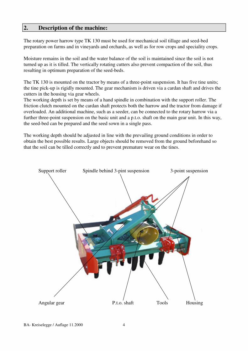
2. Description of the machine: The rotary power harrow type TK 130 must be used for mechanical soil tillage and seed-bed preparation on farms and in vineyards and orchards, as well as for row crops and speciality crops. Moisture remains in the soil and the water balance of the soil is maintained since the soil is not turned up as it is tilled. The vertically rotating cutters also prevent compaction of the soil, thus resulting in optimum preparation of the seed-beds. The TK 130 is mounted on the tractor by means of a three-point suspension. It has five tine units; the tine pick-up is rigidly mounted. The gear mechanism is driven via a cardan shaft and drives the cutters in the housing via gear wheels. The working depth is set by means of a hand spindle in combination with the support roller. The friction clutch mounted on the cardan shaft protects both the harrow and the tractor from damage if overloaded. An additional machine, such as a seeder, can be connected to the rotary harrow via a further three-point suspension on the basic unit and a p.t.o. shaft on the main gear unit. In this way, the seed-bed can be prepared and the seed sown in a single pass. The working depth should be adjusted in line with the prevailing ground conditions in order to obtain the best possible results. Large objects should be removed from the ground beforehand so that the soil can be tilled correctly and to prevent premature wear on the tines. Support roller Spindle behind 3-pint suspension 3-point suspension
Angular gear P.t.o. shaft Tools Housing
BA- Kreiselegge / Auflage 11.2000 5
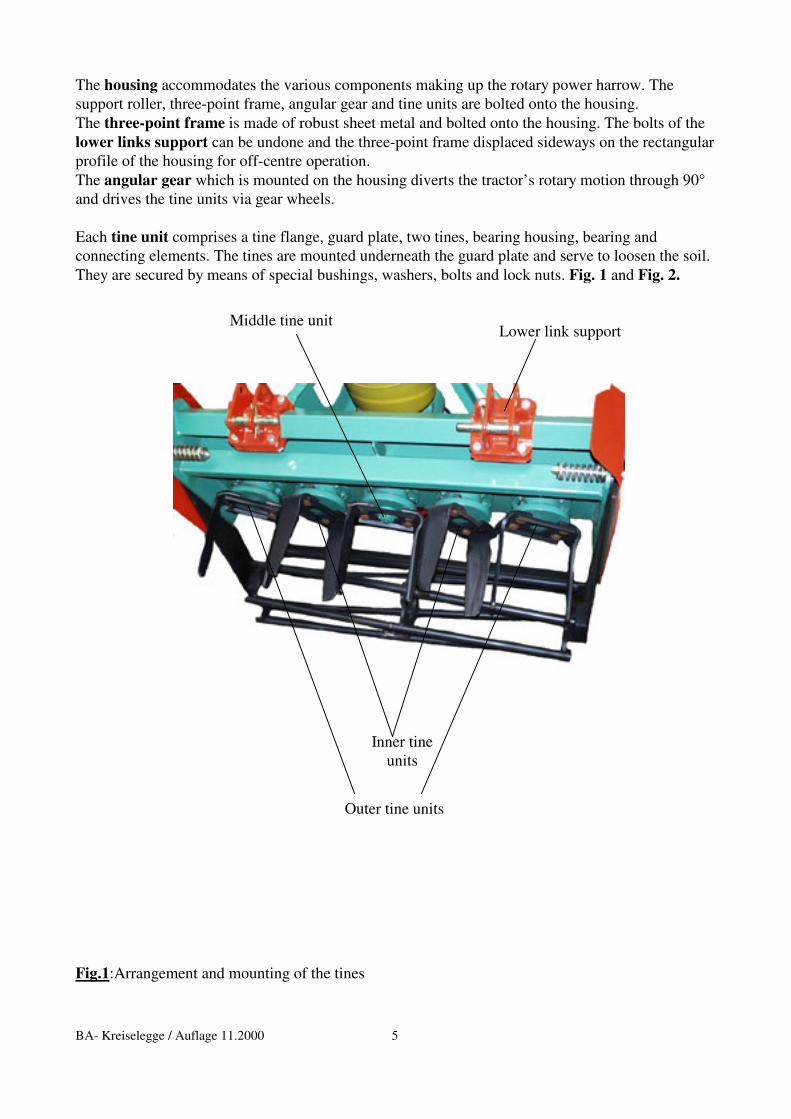
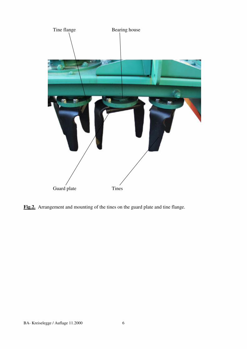
The housing accommodates the various components making up the rotary power harrow. The support roller, three-point frame, angular gear and tine units are bolted onto the housing. The three-point frame is made of robust sheet metal and bolted onto the housing. The bolts of the lower links support can be undone and the three-point frame displaced sideways on the rectangular profile of the housing for off-centre operation. The angular gear which is mounted on the housing diverts the tractor’s rotary motion through 90° and drives the tine units via gear wheels. Each tine unit comprises a tine flange, guard plate, two tines, bearing housing, bearing and connecting elements. The tines are mounted underneath the guard plate and serve to loosen the soil. They are secured by means of special bushings, washers, bolts and lock nuts. Fig. 1 and Fig. 2. Lower link support
Fig.1:Arrangement and mounting of the tines
Middle tine unit
Inner tine units
Outer tine units
BA- Kreiselegge / Auflage 11.2000 6
Tine flange Bearing house
Guard plate Tines
Fig.2. Arrangement and mounting of the tines on the guard plate and tine flange.
BA- Kreiselegge / Auflage 11.2000 7
3. Start-up and operation of the machine: * Before using the machine for the first time
- Read through the operating instructions for the rotary power harrow and additional attachments and ensure that you are fully familiar with the mode of operation of all units.
- Check that the length of the cardan shaft fits your tractor. The cardan shaft should
include an appropriate protective mechanism!
* Attachment to the tractor
- Examine tools (tines) and tine carriers for signs of wear and ensure they are secured correctly.
- Check that the support roller and three-point frame are correctly secured to the housing.
- Now connect the rotary power harrow to the tractor by means of the three-point
suspension. Secure the bolts of the upper and lower links with spring pins. Park the tractor on level ground and adjust the upper link so that the rotary power harrow is horizontal.
- Now adjust the length of the cardan shaft to match your tractor. For this purpose, hold
the two halves of the cardan shaft side-by-side in the shortest lift-out position and mark it accordingly. Shorten the inner and outer protective tube by equal amounts. Then shorten the inner and outer sliding profile by the same amount as the protective tube. Finally round off the cut edges and carefully remove all chips. Grease the sliding profiles.
- Before engaging the cardan shaft, carefully clean and grease the p.t.o. shaft of the tractor
and rotary power harrow. Then slide the cardan shaft over the p.t.o. shaft until the locking pin engages completely. The friction clutch of the cardan shaft must be mounted at the machine end.
- The working depth is now adjusted with the aid of the hand spindle in accordance with
ground condition on a firm and level substrate or by lifting the unit completely.
The rotary power harrow with fitted tools and attachments is now ready for use.
BA- Kreiselegge / Auflage 11.2000 8
* Working with the rotary harrow
- The tractor p.t.o. shaft must not be switched on until it is certain that the shaft will rotate at not more than 540 rpm at maximum engine speed.
- The p.t.o. drive must not be engaged when the tractor drives running at full load.
- The rotary power harrow may only be started and stopped from the tractor
driver’s seat.
- The TK 130 may only be switched on when there is no-one within its range of operation and hazard area (radius of 10 m from the rotary harrow) due to the risk of objects, such as stones, being hurled away from the machine. The duly prepared machine must be lowered to the working position before it is switched on. The rotary power harrow can then be switched on.
- The machine must be lowered slowly in order to avoid damage to the tools and
attachments.
- During the work, the machine must be lowered to the working depth and left with the set control hydraulics. The horizontal position of the rotary power harrow can be corrected by means of the upper link.
- The areas to be tilled should be inspected for visible large obstacles before staring so that
they can be removed from the harrow’s range and thus prevent damage to the tines and drive elements.
- If a reversing manoeuvre is required at the end of the row being tilled, the tractor p.t.o.
must be switched off and the rotary harrow allowed to come to a complete standstill before it is lifted out of the ground for the manoeuvre (risk of clods of earth being hurled off by the tines).
- If the frame has been fully fitted with tools, its stability will be assured even without
support wheels.
- Dust clouds may form when operating the rotary power harrow at higher speeds on dry ground. Light respiratory protection should therefore be worn when using a tractor without closed driver’s cab.
Kreiselegge en / Auflage 10.99 - 9 -
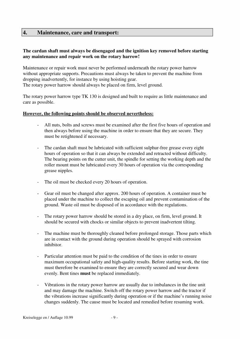
4. Maintenance, care and transport: The cardan shaft must always be disengaged and the ignition key removed before starting any maintenance and repair work on the rotary harrow! Maintenance or repair work must never be performed underneath the rotary power harrow without appropriate supports. Precautions must always be taken to prevent the machine from dropping inadvertently, for instance by using hoisting gear. The rotary power harrow should always be placed on firm, level ground. The rotary power harrow type TK 130 is designed and built to require as little maintenance and care as possible. However, the following points should be observed nevertheless:
- All nuts, bolts and screws must be examined after the first five hours of operation and then always before using the machine in order to ensure that they are secure. They must be retightened if necessary.
- The cardan shaft must be lubricated with sufficient sulphur-free grease every eight
hours of operation so that it can always be extended and retracted without difficulty. The bearing points on the cutter unit, the spindle for setting the working depth and the roller mount must be lubricated every 30 hours of operation via the corresponding grease nipples.
- The oil must be checked every 20 hours of operation.
- Gear oil must be changed after approx. 200 hours of operation. A container must be
placed under the machine to collect the escaping oil and prevent contamination of the ground. Waste oil must be disposed of in accordance with the regulations.
- The rotary power harrow should be stored in a dry place, on firm, level ground. It
should be secured with chocks or similar objects to prevent inadvertent tilting.
- The machine must be thoroughly cleaned before prolonged storage. Those parts which are in contact with the ground during operation should be sprayed with corrosion inhibitor.
- Particular attention must be paid to the condition of the tines in order to ensure
maximum occupational safety and high-quality results. Before starting work, the tine must therefore be examined to ensure they are correctly secured and wear down evenly. Bent tines must be replaced immediately.
- Vibrations in the rotary power harrow are usually due to imbalances in the tine unit
and may damage the machine. Switch off the rotary power harrow and the tractor if the vibrations increase significantly during operation or if the machine’s running noise changes suddenly. The cause must be located and remedied before resuming work.
Kreiselegge en / Auflage 10.99 - 10 -
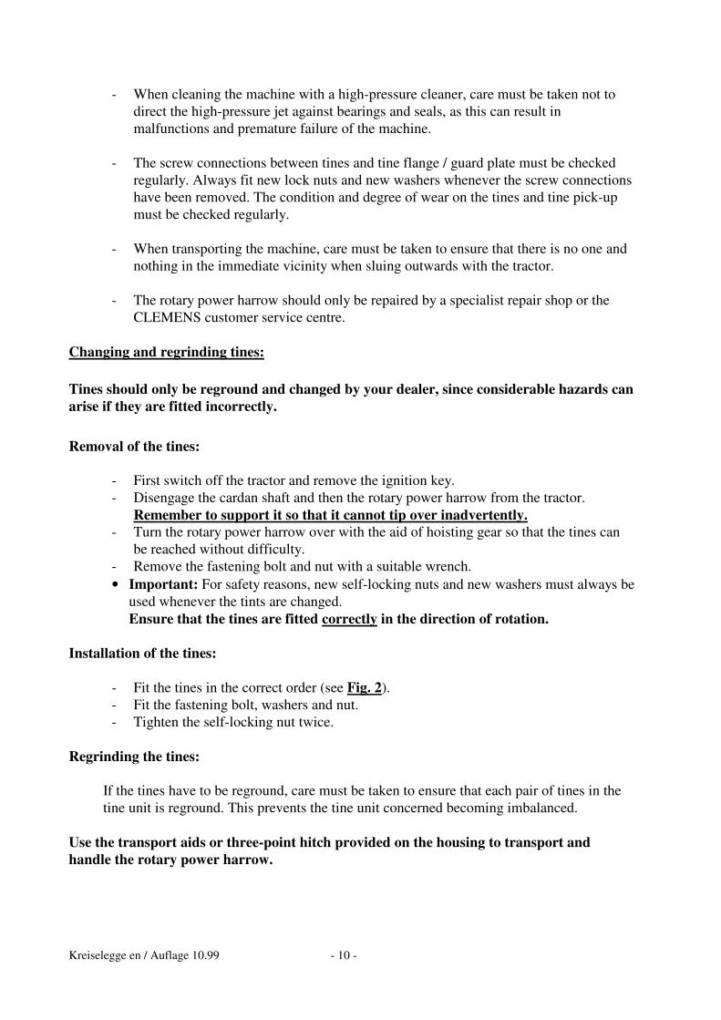
- When cleaning the machine with a high-pressure cleaner, care must be taken not to direct the high-pressure jet against bearings and seals, as this can result in malfunctions and premature failure of the machine.
- The screw connections between tines and tine flange / guard plate must be checked
regularly. Always fit new lock nuts and new washers whenever the screw connections have been removed. The condition and degree of wear on the tines and tine pick-up must be checked regularly.
- When transporting the machine, care must be taken to ensure that there is no one and
nothing in the immediate vicinity when sluing outwards with the tractor.
- The rotary power harrow should only be repaired by a specialist repair shop or the CLEMENS customer service centre.
Changing and regrinding tines: Tines should only be reground and changed by your dealer, since considerable hazards can arise if they are fitted incorrectly. Removal of the tines:
- First switch off the tractor and remove the ignition key. - Disengage the cardan shaft and then the rotary power harrow from the tractor.
Remember to support it so that it cannot tip over inadvertently. - Turn the rotary power harrow over with the aid of hoisting gear so that the tines can
be reached without difficulty. - Remove the fastening bolt and nut with a suitable wrench. • Important: For safety reasons, new self-locking nuts and new washers must always be
used whenever the tints are changed. Ensure that the tines are fitted correctly in the direction of rotation.
Installation of the tines:
- Fit the tines in the correct order (see Fig. 2). - Fit the fastening bolt, washers and nut. - Tighten the self-locking nut twice.
Regrinding the tines:
If the tines have to be reground, care must be taken to ensure that each pair of tines in the tine unit is reground. This prevents the tine unit concerned becoming imbalanced.
Use the transport aids or three-point hitch provided on the housing to transport and handle the rotary power harrow.
Kreiselegge en / Auflage 10.99 - 11 -
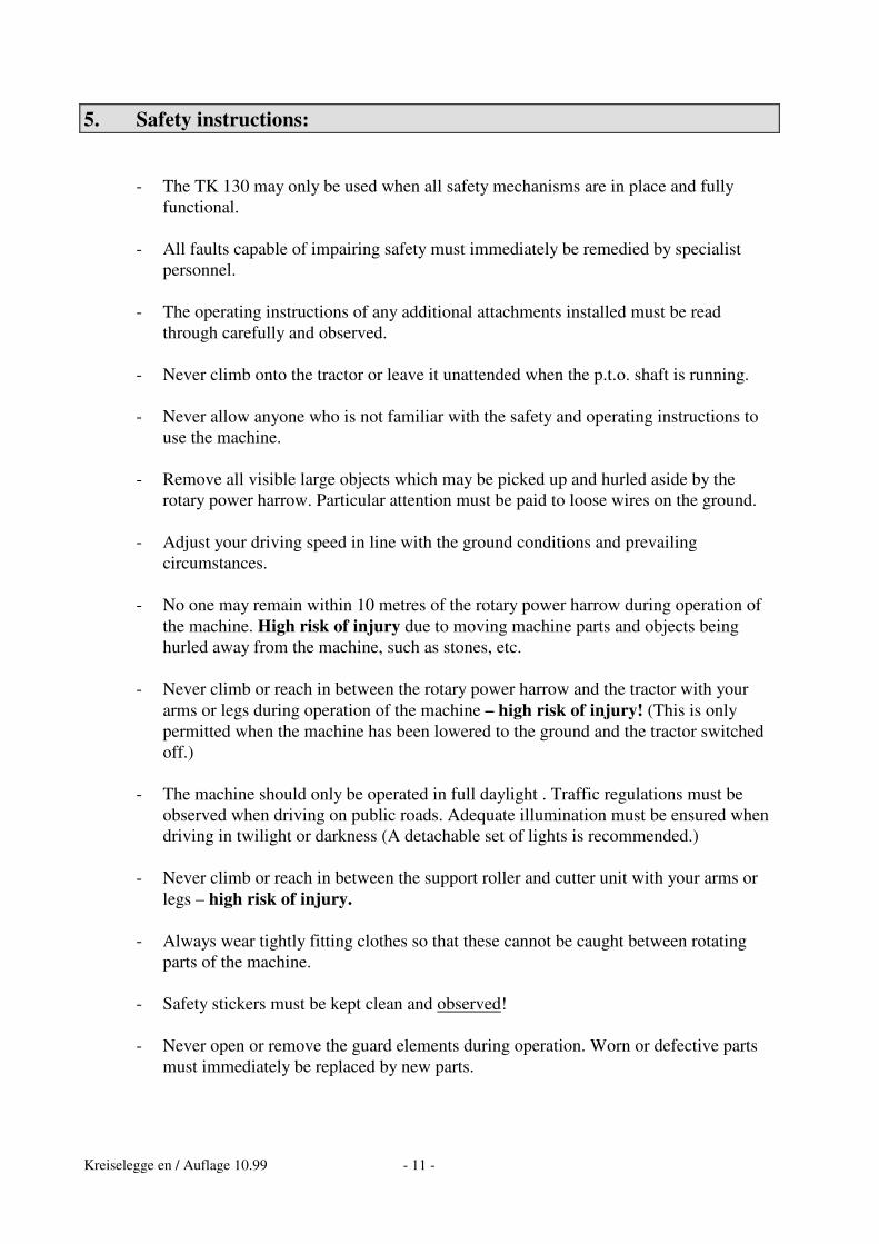
5. Safety instructions:
- The TK 130 may only be used when all safety mechanisms are in place and fully functional.
- All faults capable of impairing safety must immediately be remedied by specialist
personnel.
- The operating instructions of any additional attachments installed must be read through carefully and observed.
- Never climb onto the tractor or leave it unattended when the p.t.o. shaft is running.
- Never allow anyone who is not familiar with the safety and operating instructions to
use the machine.
- Remove all visible large objects which may be picked up and hurled aside by the rotary power harrow. Particular attention must be paid to loose wires on the ground.
- Adjust your driving speed in line with the ground conditions and prevailing
circumstances.
- No one may remain within 10 metres of the rotary power harrow during operation of the machine. High risk of injury due to moving machine parts and objects being hurled away from the machine, such as stones, etc.
- Never climb or reach in between the rotary power harrow and the tractor with your
arms or legs during operation of the machine – high risk of injury! (This is only permitted when the machine has been lowered to the ground and the tractor switched off.)
- The machine should only be operated in full daylight . Traffic regulations must be
observed when driving on public roads. Adequate illumination must be ensured when driving in twilight or darkness (A detachable set of lights is recommended.)
- Never climb or reach in between the support roller and cutter unit with your arms or
legs – high risk of injury.
- Always wear tightly fitting clothes so that these cannot be caught between rotating parts of the machine.
- Safety stickers must be kept clean and observed!
- Never open or remove the guard elements during operation. Worn or defective parts
must immediately be replaced by new parts.
Kreiselegge en / Auflage 10.99 - 12 -
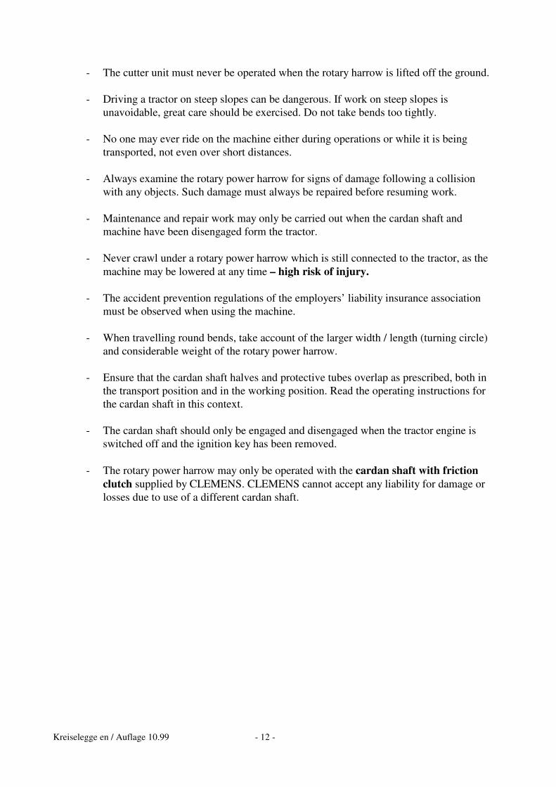
- The cutter unit must never be operated when the rotary harrow is lifted off the ground.
- Driving a tractor on steep slopes can be dangerous. If work on steep slopes is unavoidable, great care should be exercised. Do not take bends too tightly.
- No one may ever ride on the machine either during operations or while it is being
transported, not even over short distances.
- Always examine the rotary power harrow for signs of damage following a collision with any objects. Such damage must always be repaired before resuming work.
- Maintenance and repair work may only be carried out when the cardan shaft and
machine have been disengaged form the tractor.
- Never crawl under a rotary power harrow which is still connected to the tractor, as the machine may be lowered at any time – high risk of injury.
- The accident prevention regulations of the employers’ liability insurance association
must be observed when using the machine.
- When travelling round bends, take account of the larger width / length (turning circle) and considerable weight of the rotary power harrow.
- Ensure that the cardan shaft halves and protective tubes overlap as prescribed, both in
the transport position and in the working position. Read the operating instructions for the cardan shaft in this context.
- The cardan shaft should only be engaged and disengaged when the tractor engine is
switched off and the ignition key has been removed.
- The rotary power harrow may only be operated with the cardan shaft with friction clutch supplied by CLEMENS. CLEMENS cannot accept any liability for damage or losses due to use of a different cardan shaft.
Kreiselegge en / Auflage 10.99 - 13 -
6. Technical data and connections: Rotary power harrow type TK 130
Approx. dimensions: - Overall width 1340 mm - Working width 1250 mm - with cage drum roller 1300 mm
- with trellis roller 1300 mm Total weight: - with cage drum roller 440 kg - with trellis roller 520 kg
Explanation of symbols and warnings featured on the
Rotary Power Harrow type TK 130
Designed and built in accordance with European standards and regulations
Warning: Beware of danger!
Kreiselegge en / Auflage 10.99 - 14 -
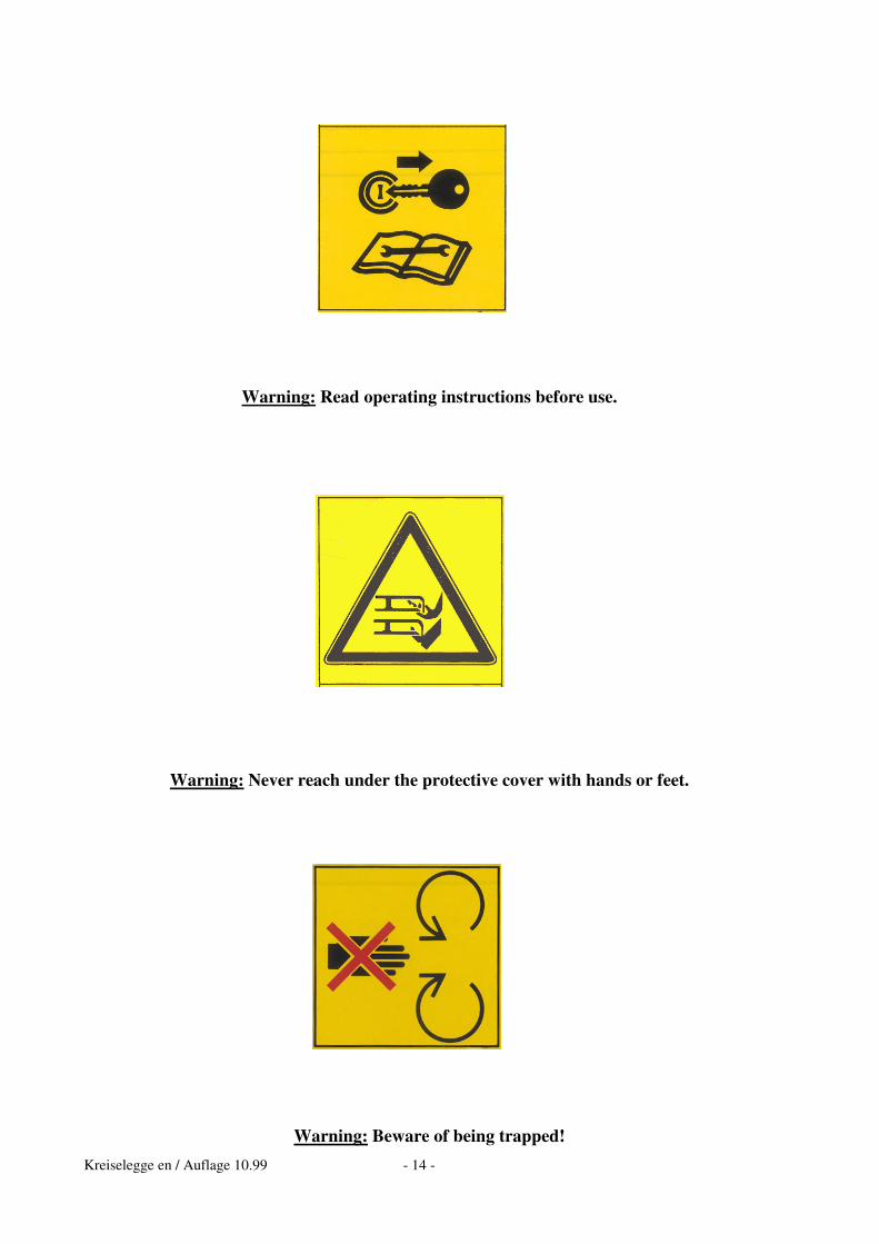
Warning: Read operating instructions before use.
Warning: Never reach under the protective cover with hands or feet.
Warning: Beware of being trapped!
Kreiselegge en / Auflage 10.99 - 15 -
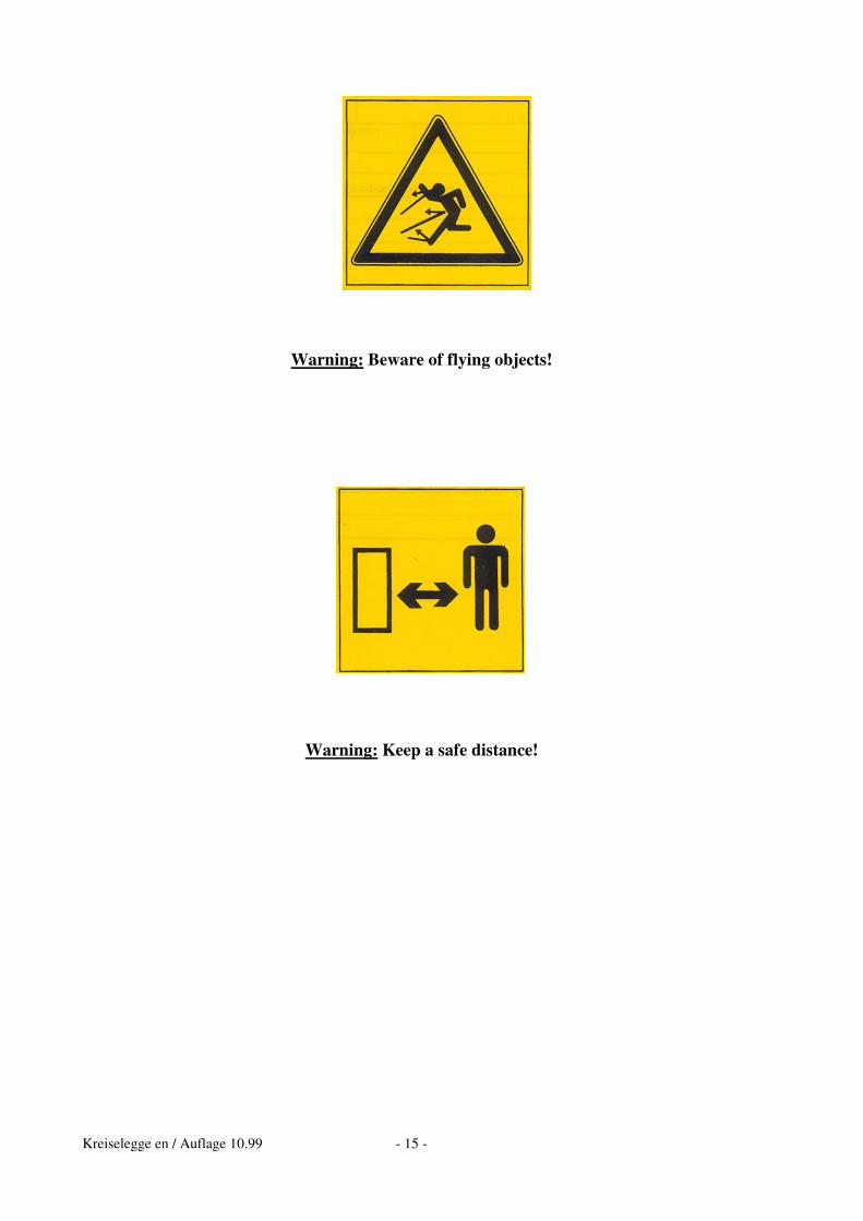
Warning: Beware of flying objects!
Warning: Keep a safe distance!
Kreiselegge en / Auflage 10.99 - 16 -
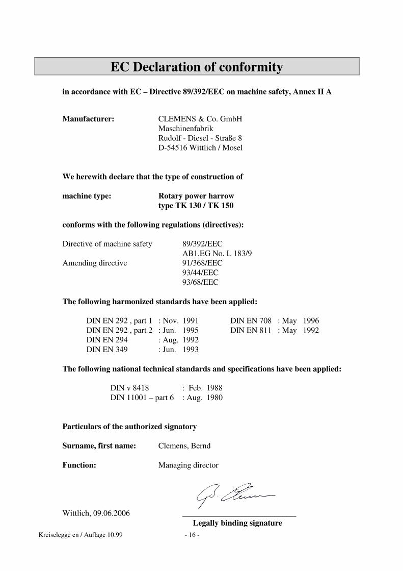
EC Declaration of conformity
in accordance with EC – Directive 89/392/EEC on machine safety, Annex II A Manufacturer: CLEMENS & Co. GmbH Maschinenfabrik Rudolf - Diesel - Straße 8 D-54516 Wittlich / Mosel We herewith declare that the type of construction of machine type: Rotary power harrow type TK 130 / TK 150 conforms with the following regulations (directives): Directive of machine safety 89/392/EEC AB1.EG No. L 183/9 Amending directive 91/368/EEC 93/44/EEC 93/68/EEC The following harmonized standards have been applied:
DIN EN 292 , part 1 : Nov. 1991 DIN EN 708 : May 1996 DIN EN 292 , part 2 : Jun. 1995 DIN EN 811 : May 1992 DIN EN 294 : Aug. 1992 DIN EN 349 : Jun. 1993
The following national technical standards and specifications have been applied:
DIN v 8418 : Feb. 1988 DIN 11001 – part 6 : Aug. 1980 Particulars of the authorized signatory Surname, first name: Clemens, Bernd Function: Managing director Wittlich, 09.06.2006 ____________________________ Legally binding signature

Kreiselegge en / Auflage 10.99 - 17 -
7. List of spare parts: Address for customer service: CLEMENS & Co. GmbH Tel.: ++49-6571 / 929 - 00 Maschinenfabrik Fax.: ++49-6571 / 929 - 192 Rudolf - Diesel - Straße 8 e-mail: [email protected] D-54516 Wittlich
Kreiselegge en / Auflage 10.99 - 18 -
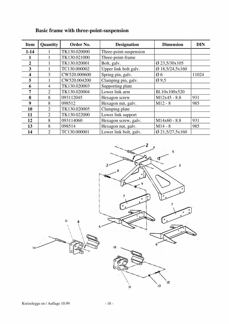
Basic frame with three-point-suspension
Item Quantity Order No. Designation Dimension DIN 1-14 1 TK130.020000 Three-point-suspension
1 1 TK130.021000 Three-point-frame 2 1 TK130.020001 Bolt, galv. Ø 23,5/30x105 3 1 TC130.000002 Upper link bolt galv. Ø 18,5/24,5x160 4 3 CW520.000600 Spring pin, galv. Ø 6 11024 5 1 CW520.004200 Clamping pin, galv. Ø 9,5 6 4 TK130.020003 Supporting plate 7 2 TK130.020004 Lower link arm Bl.10x100x520 8 8 093112045 Hexagon screw M12x45 - 8.8 931 9 8 098512 Hexagon nut, galv. M12 - 8 985
10 2 TK130.020005 Clamping plate 11 2 TK130.022000 Lower link support 12 8 093114060 Hexagon screw, galv. M14x60 - 8.8 931 13 8 098514 Hexagon nut, galv. M14 - 8 985 14 2 TC130.000001 Lower link bolt, galv. Ø 21,5/27,5x160
1
Kreiselegge en / Auflage 10.99 - 19 -
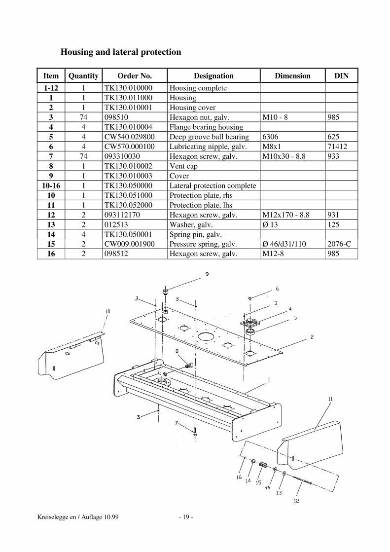
Housing and lateral protection
Item Quantity Order No. Designation Dimension DIN 1-12 1 TK130.010000 Housing complete
1 1 TK130.011000 Housing 2 1 TK130.010001 Housing cover 3 74 098510 Hexagon nut, galv. M10 - 8 985 4 4 TK130.010004 Flange bearing housing 5 4 CW540.029800 Deep groove ball bearing 6306 625 6 4 CW570.000100 Lubricating nipple, galv. M8x1 71412 7 74 093310030 Hexagon screw, galv. M10x30 - 8.8 933 8 1 TK130.010002 Vent cap 9 1 TK130.010003 Cover
10-16 1 TK130.050000 Lateral protection complete 10 1 TK130.051000 Protection plate, rhs 11 1 TK130.052000 Protection plate, lhs 12 2 093112170 Hexagon screw, galv. M12x170 - 8.8 931 13 2 012513 Washer, galv. Ø 13 125 14 4 TK130.050001 Spring pin, galv. 15 2 CW009.001900 Pressure spring, galv. Ø 46/d31/110 2076-C 16 2 098512 Hexagon screw, galv. M12-8 985
Kreiselegge en / Auflage 10.99 - 20 -
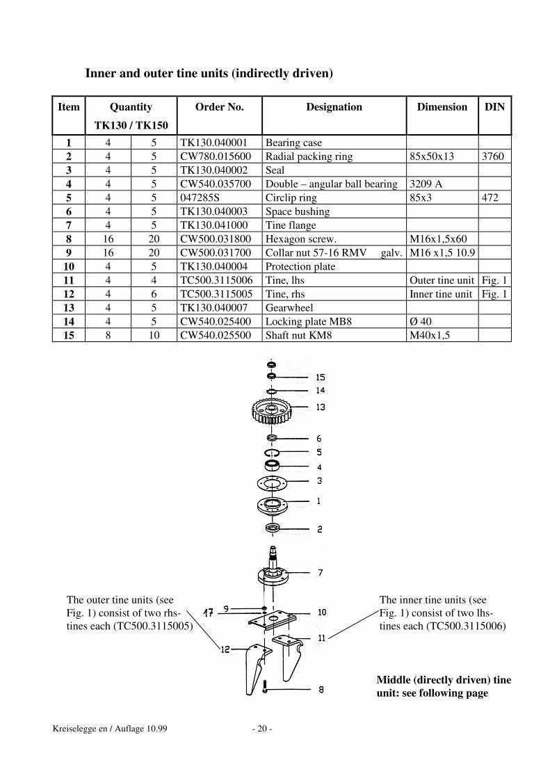
Inner and outer tine units (indirectly driven) Item Quantity
TK130 / TK150
Order No. Designation Dimension DIN
1 4 5 TK130.040001 Bearing case 2 4 5 CW780.015600 Radial packing ring 85x50x13 3760 3 4 5 TK130.040002 Seal 4 4 5 CW540.035700 Double – angular ball bearing 3209 A 5 4 5 047285S Circlip ring 85x3 472 6 4 5 TK130.040003 Space bushing 7 4 5 TK130.041000 Tine flange 8 16 20 CW500.031800 Hexagon screw. M16x1,5x60 9 16 20 CW500.031700 Collar nut 57-16 RMV galv. M16 x1,5 10.9
10 4 5 TK130.040004 Protection plate 11 4 4 TC500.3115006 Tine, lhs Outer tine unit Fig. 1 12 4 6 TC500.3115005 Tine, rhs Inner tine unit Fig. 1 13 4 5 TK130.040007 Gearwheel 14 4 5 CW540.025400 Locking plate MB8 Ø 40 15 8 10 CW540.025500 Shaft nut KM8 M40x1,5
The inner tine units (see Fig. 1) consist of two lhs-tines each (TC500.3115006)
The outer tine units (see Fig. 1) consist of two rhs-tines each (TC500.3115005)
Middle (directly driven) tine unit: see following page
Kreiselegge en / Auflage 10.99 - 21 -
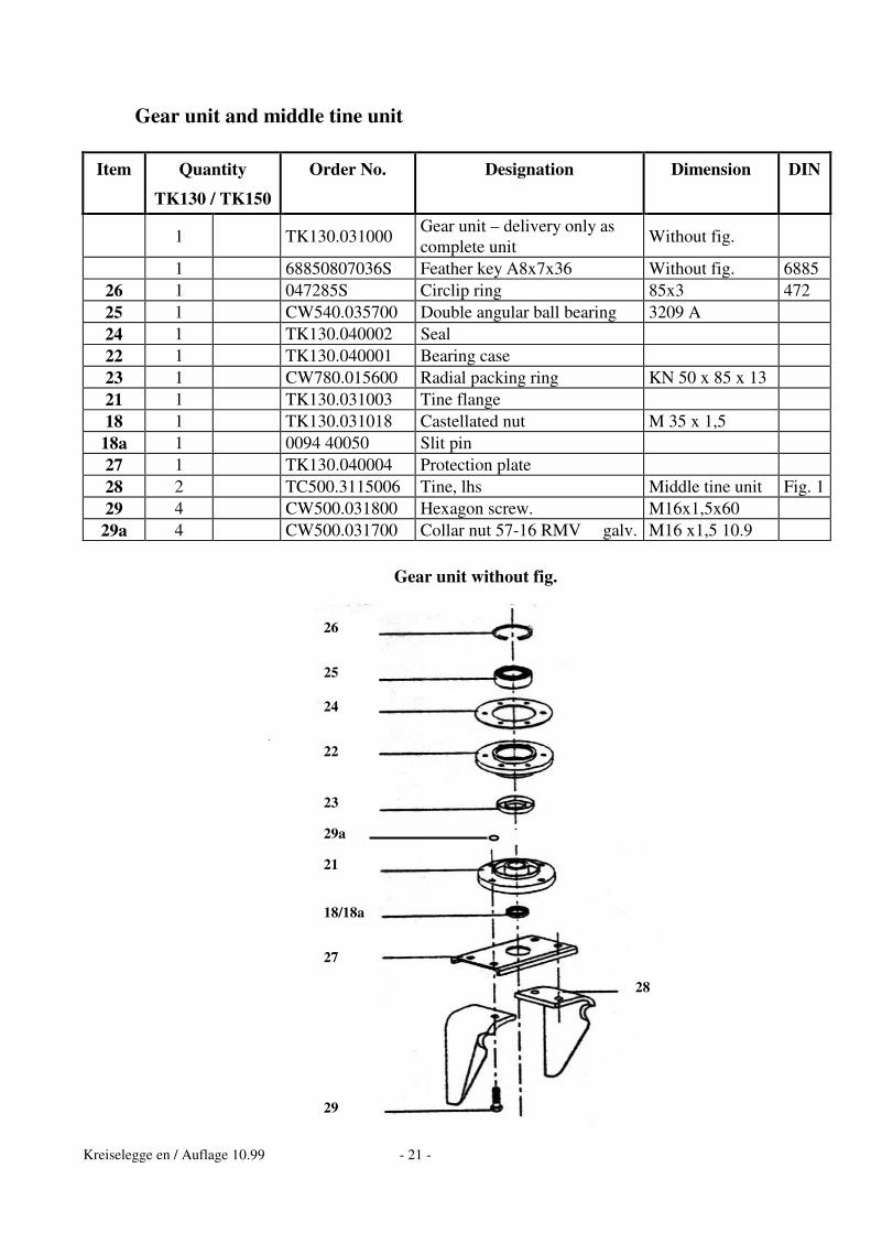
Gear unit and middle tine unit
Item Quantity
TK130 / TK150
Order No. Designation Dimension DIN
1 TK130.031000 Gear unit – delivery only as complete unit Without fig.
1 68850807036S Feather key A8x7x36 Without fig. 6885 26 1 047285S Circlip ring 85x3 472 25 1 CW540.035700 Double angular ball bearing 3209 A 24 1 TK130.040002 Seal 22 1 TK130.040001 Bearing case 23 1 CW780.015600 Radial packing ring KN 50 x 85 x 13 21 1 TK130.031003 Tine flange 18 1 TK130.031018 Castellated nut M 35 x 1,5
18a 1 0094 40050 Slit pin 27 1 TK130.040004 Protection plate 28 2 TC500.3115006 Tine, lhs Middle tine unit Fig. 1 29 4 CW500.031800 Hexagon screw. M16x1,5x60
29a 4 CW500.031700 Collar nut 57-16 RMV galv. M16 x1,5 10.9
Gear unit without fig.
26 25 24 22 23 29a 21 18/18a 27 29
28
Kreiselegge en / Auflage 10.99 - 22 -
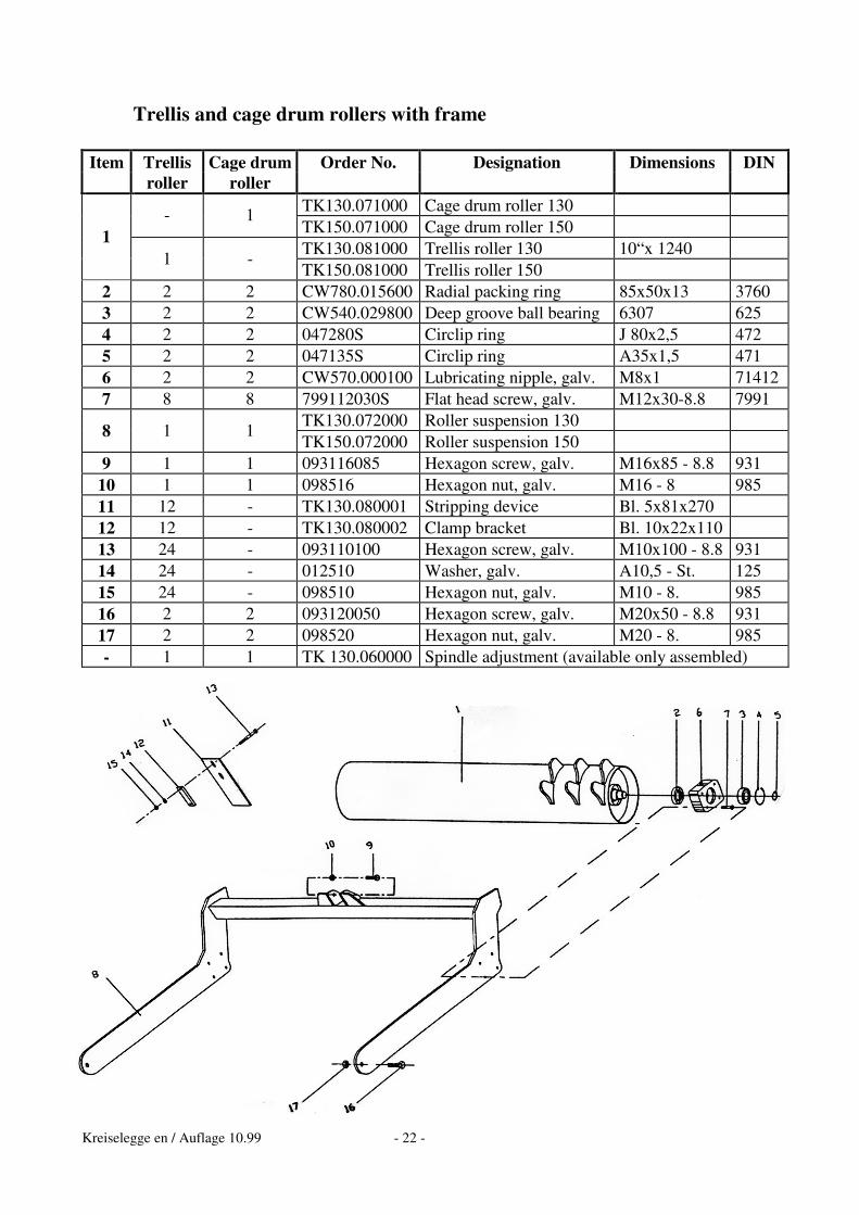
Trellis and cage drum rollers with frame Item Trellis Cage drum Order No. Designation Dimensions DIN
roller roller TK130.071000 Cage drum roller 130 - 1 TK150.071000 Cage drum roller 150 TK130.081000 Trellis roller 130 10“x 1240
1 1 -
TK150.081000 Trellis roller 150 2 2 2 CW780.015600 Radial packing ring 85x50x13 3760 3 2 2 CW540.029800 Deep groove ball bearing 6307 625 4 2 2 047280S Circlip ring J 80x2,5 472 5 2 2 047135S Circlip ring A35x1,5 471 6 2 2 CW570.000100 Lubricating nipple, galv. M8x1 71412 7 8 8 799112030S Flat head screw, galv. M12x30-8.8 7991
TK130.072000 Roller suspension 130 8 1 1 TK150.072000 Roller suspension 150
9 1 1 093116085 Hexagon screw, galv. M16x85 - 8.8 931 10 1 1 098516 Hexagon nut, galv. M16 - 8 985 11 12 - TK130.080001 Stripping device Bl. 5x81x270 12 12 - TK130.080002 Clamp bracket Bl. 10x22x110 13 24 - 093110100 Hexagon screw, galv. M10x100 - 8.8 931 14 24 - 012510 Washer, galv. A10,5 - St. 125 15 24 - 098510 Hexagon nut, galv. M10 - 8. 985 16 2 2 093120050 Hexagon screw, galv. M20x50 - 8.8 931 17 2 2 098520 Hexagon nut, galv. M20 - 8. 985 - 1 1 TK 130.060000 Spindle adjustment (available only assembled)