
INSTRUCTION MANUAL - ElectricalManuals.net Relays/Basler/BE1-67/9170900990G.pdfthe directional...
73
INSTRUCTION MANUAL FOR PHASE DIRECTIONAL OVERCURRENT RELAY BE1-67 Publication: 9 1709 00 990 Revision: G 05/2003
Transcript of INSTRUCTION MANUAL - ElectricalManuals.net Relays/Basler/BE1-67/9170900990G.pdfthe directional...
INSTRUCTION MANUALFOR
PHASE DIRECTIONAL OVERCURRENT RELAY
BE1-67
Publication: 9 1709 00 990Revision: G 05/2003

BE1-67 Introduction i
W A R N I N G !TO AVOID PERSONAL INJURY OR EQUIPMENTDAMAGE, ONLY QUALIFIED PERSONNEL SHOULDPERFORM THE PROCEDURES PRESENTED IN THISMANUAL.
INTRODUCTION
This manual provides information concerning the operation and installation of the BE1-67 Phase DirectionalOvercurrent Relay. To accomplish this, the following is provided:
! Specifications
! Functional description
! Verification and operational tests
! Mounting information
! Setting procedure/example

ii Introduction BE1-67
CONFIDENTIAL INFORMATION
OF BASLER ELECTRIC COMPANY, HIGHLAND, IL. IT IS LOANEDFOR CONFIDENTIAL USE, SUBJECT TO RETURN ON REQUEST,AND WITH THE MUTUAL UNDERSTANDING THAT IT WILL NOT BEUSED IN ANY MANNER DETRIMENTAL TO THE INTEREST OFBASLER ELECTRIC COMPANY.
First Printing: September 1988
Printed in USA
Copyright© 1988 - 2003 Basler Electric Co., Highland, IL 62249
May 2003
It is not the intention of this manual to cover all details and variations in equipment, nor does this manualprovide data for every possible contingency regarding installation or operation. The availability and design ofall features and options are subject to modification without notice. Should further information be required,contact Basler Electric Company, Highland, Illinois.
BASLER ELECTRICROUTE 143, BOX 269
HIGHLAND, IL 62249 USAhttp://www.basler.com, [email protected]
PHONE 618-654-2341 FAX 618-654-2351

BE1-67 Introduction v
MANUAL REVISION HISTORYThe following information provides a historical summary of the changes made to this instruction manual. Theserevisions are in chronological order with the most recent at the top.
Revision/Date and ECO Change
Rev G-05/03-18477 Changed Table 1-9, Style Chart, to make Timing match the BE1-67N. Corrected the Basler publication number for characteristiccurves on page 1-15. Eliminated reference to a service manual onpages 2-5 and 6-1 that no longer exists. Changed the PowerSupply portion in Sec. 3 regarding wide-range power supply(similar to the BE1-60). Updated Figures 4-1, 4-3 and 4-4 with thenew style front panels. In Setting the Pickups, Step 11, page 5-13,added the Basler publication where the B6, Very Inverse, drawingcan be found. Updated the manual style throughout.
Rev F-11/95-15426 Changed Specifications for Isolation in Section I and Dielectric Test inSection 4. Corrected Setting The Relay - An Example in Section 5.(Changed Time Delay from 5.2 seconds to 0.6 seconds in ExampleDefined and Step 11.)
Rev E-08/94-14453 Revised the entire manual to the current instruction manual format.Added internal connection diagrams, typical connection diagrams andphase rotation sensitivity.
Rev D-07/89-11106 Corrected minor typographical errors.
Rev C-02/89-10811 The arrows indicating trip direction have been reversed in Figures 4-3and 4-4.
Rev B-12/88-10724 Voltage sensing input rating corrected. Current sensing burdenstatement on page 1-10 replaced former table on same page.
Rev A-09/88-10480 Test procedure simplified. Minor editing changes.

BE1-67 Introduction iii
TABLE OF CONTENTS
SECTION 1 ! GENERAL INFORMATION . . . . . . . . . . . . . . . . . . . . . . . . . . . . . . . . . . . . . . . . . . . . . . . 1-1DESCRIPTION . . . . . . . . . . . . . . . . . . . . . . . . . . . . . . . . . . . . . . . . . . . . . . . . . . . . . . . . . . . . . . . . . 1-1LIMITED REGION OF OPERATION . . . . . . . . . . . . . . . . . . . . . . . . . . . . . . . . . . . . . . . . . . . . . . . . 1-2
Load Current Approaches Fault Current . . . . . . . . . . . . . . . . . . . . . . . . . . . . . . . . . . . . . . . . . . 1-3Weak Infeed Condition . . . . . . . . . . . . . . . . . . . . . . . . . . . . . . . . . . . . . . . . . . . . . . . . . . . . . . . . 1-3
APPLICATION . . . . . . . . . . . . . . . . . . . . . . . . . . . . . . . . . . . . . . . . . . . . . . . . . . . . . . . . . . . . . . . . . 1-4SAMPLE APPLICATION CALCULATIONS . . . . . . . . . . . . . . . . . . . . . . . . . . . . . . . . . . . . . . . . . . . 1-5
Pickup . . . . . . . . . . . . . . . . . . . . . . . . . . . . . . . . . . . . . . . . . . . . . . . . . . . . . . . . . . . . . . . . . . . . . 1-6Analysis Of Fault L . . . . . . . . . . . . . . . . . . . . . . . . . . . . . . . . . . . . . . . . . . . . . . . . . . . . . . . . . . . 1-6Analysis Of Fault M . . . . . . . . . . . . . . . . . . . . . . . . . . . . . . . . . . . . . . . . . . . . . . . . . . . . . . . . . . 1-6Conclusions . . . . . . . . . . . . . . . . . . . . . . . . . . . . . . . . . . . . . . . . . . . . . . . . . . . . . . . . . . . . . . . . 1-8
MODEL AND STYLE NUMBER . . . . . . . . . . . . . . . . . . . . . . . . . . . . . . . . . . . . . . . . . . . . . . . . . . . . 1-8Style Number Identification Chart . . . . . . . . . . . . . . . . . . . . . . . . . . . . . . . . . . . . . . . . . . . . . . . . 1-8Style Number Example . . . . . . . . . . . . . . . . . . . . . . . . . . . . . . . . . . . . . . . . . . . . . . . . . . . . . . . . 1-9
SPECIFICATIONS . . . . . . . . . . . . . . . . . . . . . . . . . . . . . . . . . . . . . . . . . . . . . . . . . . . . . . . . . . . . . . 1-9Current Sensing Input(s) . . . . . . . . . . . . . . . . . . . . . . . . . . . . . . . . . . . . . . . . . . . . . . . . . . . . . 1-10Current Sensing Burden . . . . . . . . . . . . . . . . . . . . . . . . . . . . . . . . . . . . . . . . . . . . . . . . . . . . . . 1-10Time Overcurrent Pickup Range . . . . . . . . . . . . . . . . . . . . . . . . . . . . . . . . . . . . . . . . . . . . . . . 1-10Pickup Accuracy . . . . . . . . . . . . . . . . . . . . . . . . . . . . . . . . . . . . . . . . . . . . . . . . . . . . . . . . . . . . 1-10Dropout Ratio . . . . . . . . . . . . . . . . . . . . . . . . . . . . . . . . . . . . . . . . . . . . . . . . . . . . . . . . . . . . . . 1-10Timing Characteristics . . . . . . . . . . . . . . . . . . . . . . . . . . . . . . . . . . . . . . . . . . . . . . . . . . . . . . . 1-11Time Delay Accuracy . . . . . . . . . . . . . . . . . . . . . . . . . . . . . . . . . . . . . . . . . . . . . . . . . . . . . . . . 1-11Instantaneous Overcurrent . . . . . . . . . . . . . . . . . . . . . . . . . . . . . . . . . . . . . . . . . . . . . . . . . . . . 1-11Voltage Sensing Inputs . . . . . . . . . . . . . . . . . . . . . . . . . . . . . . . . . . . . . . . . . . . . . . . . . . . . . . 1-12Voltage Sensing Burden . . . . . . . . . . . . . . . . . . . . . . . . . . . . . . . . . . . . . . . . . . . . . . . . . . . . . . 1-12Directional Unit . . . . . . . . . . . . . . . . . . . . . . . . . . . . . . . . . . . . . . . . . . . . . . . . . . . . . . . . . . . . . 1-12Sensitivity . . . . . . . . . . . . . . . . . . . . . . . . . . . . . . . . . . . . . . . . . . . . . . . . . . . . . . . . . . . . . . . . . 1-12Characteristic Angle . . . . . . . . . . . . . . . . . . . . . . . . . . . . . . . . . . . . . . . . . . . . . . . . . . . . . . . . . 1-12Limited Range of Operation (Optional) . . . . . . . . . . . . . . . . . . . . . . . . . . . . . . . . . . . . . . . . . . . 1-13Frequency Range . . . . . . . . . . . . . . . . . . . . . . . . . . . . . . . . . . . . . . . . . . . . . . . . . . . . . . . . . . . 1-13Power Supply . . . . . . . . . . . . . . . . . . . . . . . . . . . . . . . . . . . . . . . . . . . . . . . . . . . . . . . . . . . . . . 1-13Target Indicators . . . . . . . . . . . . . . . . . . . . . . . . . . . . . . . . . . . . . . . . . . . . . . . . . . . . . . . . . . . 1-13Output Circuits . . . . . . . . . . . . . . . . . . . . . . . . . . . . . . . . . . . . . . . . . . . . . . . . . . . . . . . . . . . . . 1-14Isolation . . . . . . . . . . . . . . . . . . . . . . . . . . . . . . . . . . . . . . . . . . . . . . . . . . . . . . . . . . . . . . . . . . 1-14UL Recognized . . . . . . . . . . . . . . . . . . . . . . . . . . . . . . . . . . . . . . . . . . . . . . . . . . . . . . . . . . . . . 1-14Surge Withstand Capability . . . . . . . . . . . . . . . . . . . . . . . . . . . . . . . . . . . . . . . . . . . . . . . . . . . 1-14Operating Temperature . . . . . . . . . . . . . . . . . . . . . . . . . . . . . . . . . . . . . . . . . . . . . . . . . . . . . . 1-14Storage Temperature . . . . . . . . . . . . . . . . . . . . . . . . . . . . . . . . . . . . . . . . . . . . . . . . . . . . . . . . 1-14Shock . . . . . . . . . . . . . . . . . . . . . . . . . . . . . . . . . . . . . . . . . . . . . . . . . . . . . . . . . . . . . . . . . . . . 1-14Vibration . . . . . . . . . . . . . . . . . . . . . . . . . . . . . . . . . . . . . . . . . . . . . . . . . . . . . . . . . . . . . . . . . . 1-14
CHARACTERISTIC CURVES . . . . . . . . . . . . . . . . . . . . . . . . . . . . . . . . . . . . . . . . . . . . . . . . . . . . 1-15
SECTION 2 ! HUMAN-MACHINE INTERFACE . . . . . . . . . . . . . . . . . . . . . . . . . . . . . . . . . . . . . . . . . . 2-1
SECTION 3 ! FUNCTIONAL DESCRIPTION . . . . . . . . . . . . . . . . . . . . . . . . . . . . . . . . . . . . . . . . . . . . 3-1GENERAL . . . . . . . . . . . . . . . . . . . . . . . . . . . . . . . . . . . . . . . . . . . . . . . . . . . . . . . . . . . . . . . . . . . . . 3-1INPUT CIRCUITS . . . . . . . . . . . . . . . . . . . . . . . . . . . . . . . . . . . . . . . . . . . . . . . . . . . . . . . . . . . . . . . 3-1
Current Sensing . . . . . . . . . . . . . . . . . . . . . . . . . . . . . . . . . . . . . . . . . . . . . . . . . . . . . . . . . . . . . 3-1Voltage Sensing . . . . . . . . . . . . . . . . . . . . . . . . . . . . . . . . . . . . . . . . . . . . . . . . . . . . . . . . . . . . . 3-2
DIRECTIONAL ELEMENT . . . . . . . . . . . . . . . . . . . . . . . . . . . . . . . . . . . . . . . . . . . . . . . . . . . . . . . . 3-2Characteristic Angle . . . . . . . . . . . . . . . . . . . . . . . . . . . . . . . . . . . . . . . . . . . . . . . . . . . . . . . . . . 3-2Limited Region Of Operation . . . . . . . . . . . . . . . . . . . . . . . . . . . . . . . . . . . . . . . . . . . . . . . . . . . 3-3
INDICATORS . . . . . . . . . . . . . . . . . . . . . . . . . . . . . . . . . . . . . . . . . . . . . . . . . . . . . . . . . . . . . . . . . . 3-4

iv Introduction BE1-67
Inhibit LED's . . . . . . . . . . . . . . . . . . . . . . . . . . . . . . . . . . . . . . . . . . . . . . . . . . . . . . . . . . . . . . . . 3-4Timing LED's . . . . . . . . . . . . . . . . . . . . . . . . . . . . . . . . . . . . . . . . . . . . . . . . . . . . . . . . . . . . . . . . 3-4Power LED's . . . . . . . . . . . . . . . . . . . . . . . . . . . . . . . . . . . . . . . . . . . . . . . . . . . . . . . . . . . . . . . . 3-4Function Targets . . . . . . . . . . . . . . . . . . . . . . . . . . . . . . . . . . . . . . . . . . . . . . . . . . . . . . . . . . . . . 3-4Element Targets . . . . . . . . . . . . . . . . . . . . . . . . . . . . . . . . . . . . . . . . . . . . . . . . . . . . . . . . . . . . . 3-4
POWER SUPPLY . . . . . . . . . . . . . . . . . . . . . . . . . . . . . . . . . . . . . . . . . . . . . . . . . . . . . . . . . . . . . . . 3-4LOGIC CIRCUITS . . . . . . . . . . . . . . . . . . . . . . . . . . . . . . . . . . . . . . . . . . . . . . . . . . . . . . . . . . . . . . . 3-5
Microprocessor . . . . . . . . . . . . . . . . . . . . . . . . . . . . . . . . . . . . . . . . . . . . . . . . . . . . . . . . . . . . . . 3-5Outputs . . . . . . . . . . . . . . . . . . . . . . . . . . . . . . . . . . . . . . . . . . . . . . . . . . . . . . . . . . . . . . . . . . . . 3-5
TARGET INDICATOR CIRCUITS . . . . . . . . . . . . . . . . . . . . . . . . . . . . . . . . . . . . . . . . . . . . . . . . . . . 3-6
SECTION 4 ! INSTALLATION . . . . . . . . . . . . . . . . . . . . . . . . . . . . . . . . . . . . . . . . . . . . . . . . . . . . . . . . 4-1GENERAL . . . . . . . . . . . . . . . . . . . . . . . . . . . . . . . . . . . . . . . . . . . . . . . . . . . . . . . . . . . . . . . . . . . . . 4-1OPERATING PRECAUTIONS . . . . . . . . . . . . . . . . . . . . . . . . . . . . . . . . . . . . . . . . . . . . . . . . . . . . . . 4-1DIELECTRIC TEST . . . . . . . . . . . . . . . . . . . . . . . . . . . . . . . . . . . . . . . . . . . . . . . . . . . . . . . . . . . . . . 4-1MOUNTING . . . . . . . . . . . . . . . . . . . . . . . . . . . . . . . . . . . . . . . . . . . . . . . . . . . . . . . . . . . . . . . . . . . . 4-1CONNECTIONS . . . . . . . . . . . . . . . . . . . . . . . . . . . . . . . . . . . . . . . . . . . . . . . . . . . . . . . . . . . . . . . . 4-8
SECTION 5 ! TESTING . . . . . . . . . . . . . . . . . . . . . . . . . . . . . . . . . . . . . . . . . . . . . . . . . . . . . . . . . . . . . 5-1GENERAL . . . . . . . . . . . . . . . . . . . . . . . . . . . . . . . . . . . . . . . . . . . . . . . . . . . . . . . . . . . . . . . . . . . . . 5-1
Equipment Required . . . . . . . . . . . . . . . . . . . . . . . . . . . . . . . . . . . . . . . . . . . . . . . . . . . . . . . . . . 5-1Preliminary Setup . . . . . . . . . . . . . . . . . . . . . . . . . . . . . . . . . . . . . . . . . . . . . . . . . . . . . . . . . . . . 5-1
VERIFICATION TESTING . . . . . . . . . . . . . . . . . . . . . . . . . . . . . . . . . . . . . . . . . . . . . . . . . . . . . . . . . 5-3Time Overcurrent Pickup Test . . . . . . . . . . . . . . . . . . . . . . . . . . . . . . . . . . . . . . . . . . . . . . . . . . . 5-3Instantaneous Overcurrent Pickup Test . . . . . . . . . . . . . . . . . . . . . . . . . . . . . . . . . . . . . . . . . . . 5-4Directional Verification . . . . . . . . . . . . . . . . . . . . . . . . . . . . . . . . . . . . . . . . . . . . . . . . . . . . . . . . . 5-4
TIMING CURVE VERIFICATION . . . . . . . . . . . . . . . . . . . . . . . . . . . . . . . . . . . . . . . . . . . . . . . . . . 5-10DIRECTIONAL SETTING PROCEDURE . . . . . . . . . . . . . . . . . . . . . . . . . . . . . . . . . . . . . . . . . . . . 5-11
Characteristic Angle . . . . . . . . . . . . . . . . . . . . . . . . . . . . . . . . . . . . . . . . . . . . . . . . . . . . . . . . . 5-11Limited Region Of Operation . . . . . . . . . . . . . . . . . . . . . . . . . . . . . . . . . . . . . . . . . . . . . . . . . . . 5-11Verifying Relay Settings . . . . . . . . . . . . . . . . . . . . . . . . . . . . . . . . . . . . . . . . . . . . . . . . . . . . . . 5-12
SETTING THE RELAY - AN EXAMPLE . . . . . . . . . . . . . . . . . . . . . . . . . . . . . . . . . . . . . . . . . . . . . 5-12Example Defined . . . . . . . . . . . . . . . . . . . . . . . . . . . . . . . . . . . . . . . . . . . . . . . . . . . . . . . . . . . . 5-12Setting The Pickups . . . . . . . . . . . . . . . . . . . . . . . . . . . . . . . . . . . . . . . . . . . . . . . . . . . . . . . . . 5-13Setting The Direction . . . . . . . . . . . . . . . . . . . . . . . . . . . . . . . . . . . . . . . . . . . . . . . . . . . . . . . . . 5-13Setting The Limited Range Of Operation . . . . . . . . . . . . . . . . . . . . . . . . . . . . . . . . . . . . . . . . . 5-13
SECTION 6 ! MAINTENANCE . . . . . . . . . . . . . . . . . . . . . . . . . . . . . . . . . . . . . . . . . . . . . . . . . . . . . . . . 6-1GENERAL . . . . . . . . . . . . . . . . . . . . . . . . . . . . . . . . . . . . . . . . . . . . . . . . . . . . . . . . . . . . . . . . . . . . . 6-1IN-HOUSE REPAIR . . . . . . . . . . . . . . . . . . . . . . . . . . . . . . . . . . . . . . . . . . . . . . . . . . . . . . . . . . . . . . 6-1STORAGE . . . . . . . . . . . . . . . . . . . . . . . . . . . . . . . . . . . . . . . . . . . . . . . . . . . . . . . . . . . . . . . . . . . . . 6-1TEST PLUG . . . . . . . . . . . . . . . . . . . . . . . . . . . . . . . . . . . . . . . . . . . . . . . . . . . . . . . . . . . . . . . . . . . . 6-1
BE1-67 General Information 1-1
SECTION 1 GENERAL INFORMATION
DESCRIPTION
BE1-67 Phase Directional Overcurrent Relays are designed for the protection of transmission and distributionlines where the direction as well as the magnitude of the fault current (or power flow) are to be considered inthe tripping decision.
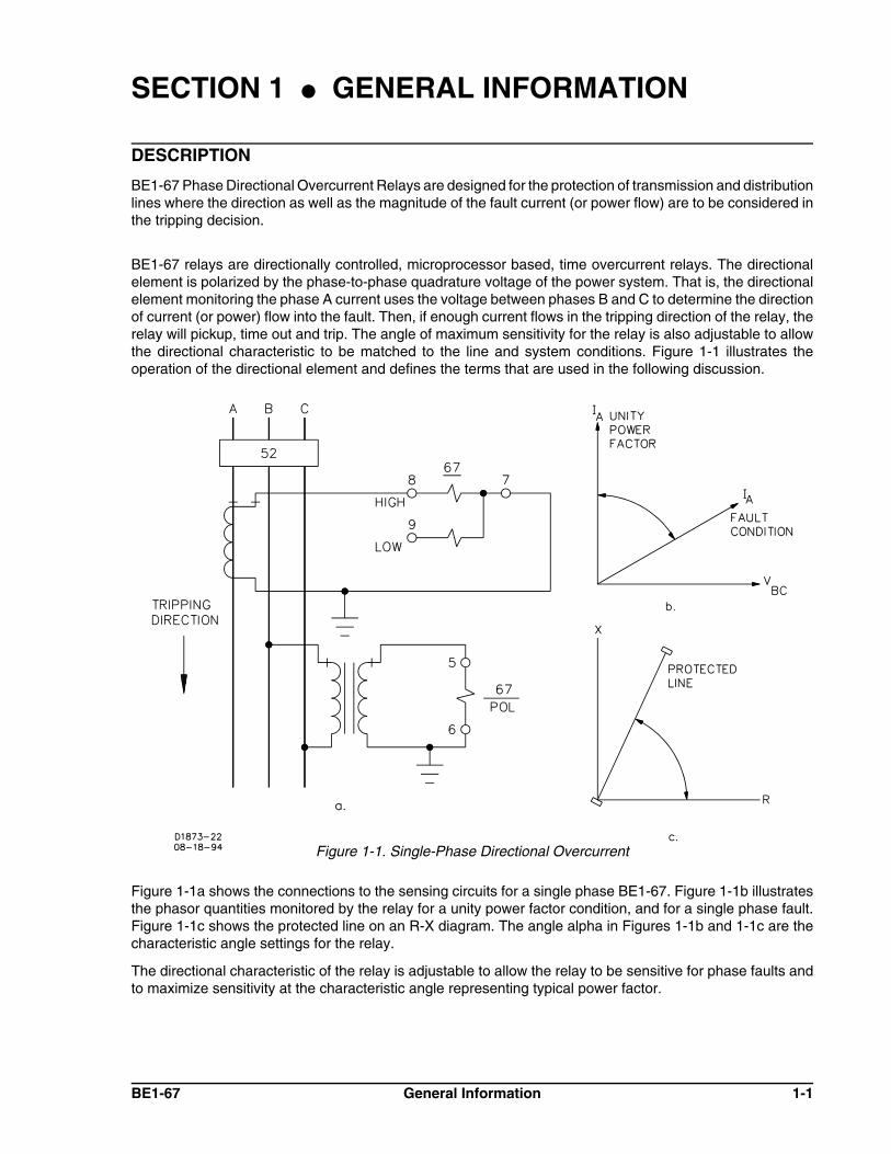
BE1-67 relays are directionally controlled, microprocessor based, time overcurrent relays. The directionalelement is polarized by the phase-to-phase quadrature voltage of the power system. That is, the directionalelement monitoring the phase A current uses the voltage between phases B and C to determine the directionof current (or power) flow into the fault. Then, if enough current flows in the tripping direction of the relay, therelay will pickup, time out and trip. The angle of maximum sensitivity for the relay is also adjustable to allowthe directional characteristic to be matched to the line and system conditions. Figure 1-1 illustrates theoperation of the directional element and defines the terms that are used in the following discussion.
Figure 1-1. Single-Phase Directional Overcurrent
Figure 1-1a shows the connections to the sensing circuits for a single phase BE1-67. Figure 1-1b illustratesthe phasor quantities monitored by the relay for a unity power factor condition, and for a single phase fault.Figure 1-1c shows the protected line on an R-X diagram. The angle alpha in Figures 1-1b and 1-1c are thecharacteristic angle settings for the relay.
The directional characteristic of the relay is adjustable to allow the relay to be sensitive for phase faults andto maximize sensitivity at the characteristic angle representing typical power factor.

1-2 General Information BE1-67
Figure 1-2. Trip Direction Defined
Twelve standard time-current characteristic curves are available to aid in the coordination of this relay withother protective devices in the system. These include seven characteristic curves that are standard in NorthAmerica and five that are compatible with British or IEC standards requirements. In addition, an option allowsthe relay to be supplied with all of these curves any of which may be switch selected to suit requirements atthe time of installation.
Table 1-1. Selection Considerations For Characteristic Curves
StyleDesignation
CharacteristicShape Special Characteristics
B1 Short Inverse Relatively short time, desirable wherepreserving system stability is a criticalfactor.
B2, E2 Long Inverse Provides protection for starting motors andoverloads of short duration.
B3 Definite Time Definite Time Fixed time delay according tothe time dial setting. Useful for sequentialtripping schemes.
B4, E4 Moderately Inverse Accommodates moderate load changes asmay occur on parallel lines where one linemay occasionally have to carry both loads.
B5, E5 Inverse Provide additional variations of the inversecharacteristic, thereby allowing flexibility inmeeting load variations, or in coordinatingwith other relays.
B6. E6 Very Inverse
B7, E7 Extremely Inverse
If the supply to the protected portion of the system is constant, and if the magnitude of the fault current isdetermined primarily by the location of the fault on the line, the selection of a more inverse time characteristicis more desirable to provide selective coordination with adjacent line protection. However, if the capacity ofthe supply varies significantly over a period (such as a day), a less inverse time or even the definite timecharacteristic, may be preferred to provide smoother coordination.
LIMITED REGION OF OPERATION
A limited region-of-operation option is available toprovide additional protection against false trippingon mutually coupled lines. Faults on adjacent linesthat share the same poles, towers or right-of-waymay induce currents on the protected line whichappear as fault currents in the tripping direction.The limited region of operation mode providesdiscrimination between faults on the protected lineand faults on the adjacent line. To order this option,specify option 3-5 or 3-6.
One consideration in applying a phase directionalovercurrent relay is the definition of trip direction.For most applications, the setting of the relaydirectional element is based upon the impedancecharacteristics of a given circuit. This angle is thenused as the maximum torque angle and any currentflowing in the half-plane defined by this angle isconsidered to be in the trip direction.

BE1-67 General Information 1-3
Figure 1-3. Weak Infeed Phenomenon
Figure 1-4. Limiting the Region of Operation
Figure 1-2 illustrates the trip and non-trip directions.
However, there are at least two situations where the half-plane trip region is not adequate. They are when loadcurrent approaches the fault current and when leading current flows in the non-trip direction above the relaypickup setting.
Load Current Approaches Fault Current
Pickup settings on a phase overcurrent device arenormally set below the expected fault currentlevels on that line by some margin. Consequently,it is possible for load current to approach (orexceed) the pickup setting on the relay. This couldlead to an undesirable trip for an acceptable loadcondition.
Weak Infeed Condition
During a period of abnormally low system voltage,leading power factor current above relay pickupcan flow in the non-trip direction of a line.Probable current sources are outlying capacitorbanks. This could cause the current to be sensedas lagging current flowing in the trip direction andleading to an undesirable trip. (A condition oftenreferred to as weak infeed because the lowervoltage system - where load is present - attemptsto correct the undervoltage condition on the highervoltage system.) Refer to Figure 1-3.
Both of the previous conditions can be eased bylimiting the area of the trip region. Specifically, theangle on each side of the torque angle vector canbe adjusted to be less than 90 degrees. Thislimits the trip region area to only a portion of thehalf-plane usually defined as the trip direction.This limited region-of-operation characteristic(shown in Figure 1-4) is available by specifyingoption 3-5 or 3-6.

1-4 General Information BE1-67
APPLICATION
Without the ability to act on the direction of current flow, it is difficult to coordinate the settings of timeovercurrent relays on lines that interconnect a series of substations. Without this capability, either undesiredtripping of adjacent lines may occur. Or a fault may go undetected because of the high settings required bynon-directional relays.
With directional time overcurrent relays, the settings and time delays can be decreased and the undesiredtripping eliminated. Figure 1-5 illustrates the use of directional overcurrent relays on a group of interconnecteddistribution substations fed from a common source. In this example, non-directional overcurrent relays (51)are used to protect the lines leaving the supply bus because there is only one source of fault current. However,the breakers at the load buses (C, D, E and F) are protected by directional time overcurrent relays (67) toprevent overtripping in the event of a fault. This will remove the faulted line and retain service to the connectedloads.
In the case where two sources of power can supply fault current, as shown in Figure 1-6, directionalovercurrent relays will need to be applied to each end of the protected lines to prevent undesired tripping.
Figure 1-5. Substations Fed From One Source

BE1-67 General Information 1-5
Figure 1-7. Significant Faults for Breaker A
Figure 1-6. Substations Fed From Two Sources
SAMPLE APPLICATION CALCULATIONS
In this sample illustrated by Figure 1-7, a three-phase, 60 hertz, BE1-67 relay is used at breaker position A.Assumed options for the relay include switch-selectable characteristic curves, switch-selectable characteristicangle and a directional instantaneous output.

1-6 General Information BE1-67
Using this relay under the stated conditions, there are five settings to be established:
! Pickup of the timed element! Time dial! Timing characteristic! Torque angle! Pickup of the directional instantaneous unit
In arriving at a satisfactory setting for each variable, consideration must be given as to how the relaycoordinates with other upstream and downstream tripping devices. In particular, the time-currentcharacteristics of all relevant devices must be systematically considered for each fault condition that canoccur.
The ensuing analysis considers pickup settings first, followed by a detailed examination of the three scenariosindicated in Figure 1-7 as faults L, M and N. These will be individually considered with regard to the fivesettings listed previously and particularly the last four.
Pickup
When considering relay pickup, it is desirable to set the relay above the maximum load that the feeder isexpected to supply at any given time in the defined direction. Often this quantity is limited only by the breakersize or the current carrying capacity of the line itself.
Returning to Figure 1-7, if it is assumed that the maximum lead current is 1,200 amperes for line AC and amaximum CT ratio of 400:1, then:
Timed pickup setting = (1200)(1 ÷ 400)(1.25) = 3.75 amperes
(The 1.25 factor represents a margin of safety.)
Analysis Of Fault L
In Figure 1-7, assume the following fault L currents.
! IA(L) = 3,000 amperes at an angle of -65 degrees
! ID(L) = 6,400 amperes at an angle of -60 degrees
Based on these fault currents, the BE1-67 relay at A will pickup and begin to time out. But the primary concernis that the relay at D trips before the one at A. This is accomplished by selecting the appropriate pickup, timedial and characteristic for the 67 A device. Note in Figure 1-8, illustration a, that the 67D characteristic curvemust be completely under the 67 A curve for current greater than the 67A pickup point. A coordinating timeinterval of0.2 to 0.5 seconds between the curves is usually recommended to accommodate breaker clearingtime plus a safety margin. The Time Dial should be set to provide this coordination margin.
Usually, time-characteristic curves are chosen to coordinate with existing system devices. Consequently, if67D is extremely inverse, the 67A relay might well be set to the B7 curve (extremely inverse). To select thecurve, use the rotary switch behind the front panel of the relay.
The fault current level seen by IA (3,000 amperes) also confirms that the setting chosen (3.75 A x 400 = 1,500primary amperes) is sensitive enough to detect remote end faults. This is assuming that the fault current isnot limited by fault impedance.
Analysis Of Fault M
In Figure 1-7, assume the following fault M currents:
! IA(M) = 4,600 amperes at an angle of -60 degrees
! IE(M) = 400 amperes at an angle of -65 degrees
BE1-67 General Information 1-7
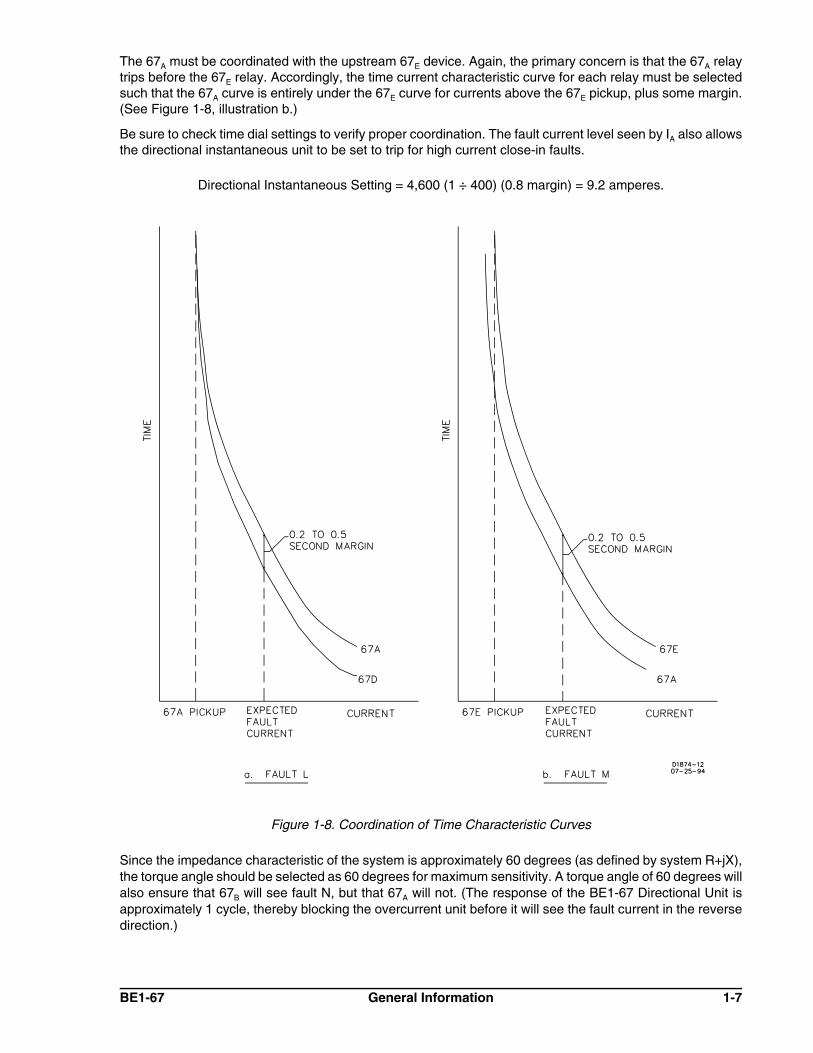
The 67A must be coordinated with the upstream 67E device. Again, the primary concern is that the 67A relaytrips before the 67E relay. Accordingly, the time current characteristic curve for each relay must be selectedsuch that the 67A curve is entirely under the 67E curve for currents above the 67E pickup, plus some margin.(See Figure 1-8, illustration b.)
Be sure to check time dial settings to verify proper coordination. The fault current level seen by IA also allowsthe directional instantaneous unit to be set to trip for high current close-in faults.
Directional Instantaneous Setting = 4,600 (1 ÷ 400) (0.8 margin) = 9.2 amperes.
Figure 1-8. Coordination of Time Characteristic Curves
Since the impedance characteristic of the system is approximately 60 degrees (as defined by system R+jX),the torque angle should be selected as 60 degrees for maximum sensitivity. A torque angle of 60 degrees willalso ensure that 67B will see fault N, but that 67A will not. (The response of the BE1-67 Directional Unit isapproximately 1 cycle, thereby blocking the overcurrent unit before it will see the fault current in the reversedirection.)

1-8 General Information BE1-67
Conclusions
Taking into consideration the requirements imposed by each of three possible fault conditions, the fiverequired settings for the relay at breaker A in this application are summarized in Table 1-2.
Table 1-2. Required Breaker Settings
Variable Suitable Setting
Pickup for timed element 3.75 A (low range, TAP 1)
Time dial As required for proper coordination margin
Timing characteristic B7 (rotary switch position 7)
Directional instantaneous element 9.20 A (potentiometer adjustment)
Torque angle 60° characteristic angle
MODEL AND STYLE NUMBER
Style Number Identification Chart
BE1-67 Phase Directional Overcurrent Relay electrical characteristics and operational features are definedby a combination of letters and numbers that make up the style number. Refer to Figure 1-9 for the StyleNumber Identification Chart. Model numbers BE1-67 designate the relay as a Basler Electric, Class 100,Phase Directional Overcurrent Relay. The model number together with the style number describes the optionsincluded in a specific device and appear on the front panel, drawout cradle and inside the case assembly.Upon receipt of a relay, be sure to check the style number against the requisition and the packing list to ensurethat they agree.
Figure 1-9. Style Number Identification Chart

BE1-67 General Information 1-9
Style Number Example
Suppose, for example, it was decided that three-phase packaging of the directional overcurrent function (67)would be best for an application. Then the first character of the style number would be B.
Suppose further that this is a 60 hertz power system and that the pickup setting for the time overcurrent func-tion is to be 4.6 amperes. Then the second character of the style would then be 1. At this point it should benoted on the installation instructions and drawings that the relay should be connected for the HIGH range andthat the front panel TAP RANGE plate should be adjusted so that the word HIGH shows.
If normally open output contacts are to be used for tripping the breaker, output option E is selected as the thirdcharacter.
If the required characteristic curve shape is not known prior to the installation of the protection package, timingoption Z2 could be specified. This allows the proper characteristic curve to be set in the field. (This also allowsa relay type to be stocked and used in other applications, thereby reducing stocking requirements.)
Continuing this hypothetical example, if a majority of the substations in the system have either 48 or 125 Vdcstation battery supplies, a type Y power supply option provides further standardization in the ordering andstocking process.
The next style character is B if current operated targets are desired. These have an advantage over internallyoperated targets because they confirm that a current signal flowed in the output circuit and resulted in a trip.(However, as the style chart notes, current operated targets are only available when a normally open contactis specified.) Internally operated targets only provide an indication that the associated contact attempted totrip the breaker.
If a directional instantaneous overcurrent element is needed, the eighth character of the style number will thenbe 3.
Will the breaker be periodically trip tested? If the normal procedure calls for the technician to close the relaycontacts, the push-to-energize output option (C) provides the convenience to do this.
If a fixed characteristic angle is preferred to a continuously adjustable angle and it is useful to have a contactmonitoring the power supply of the relay, option 3 should be a 4.
Finally, if relays are to be semi-flush mounted in the panel, the last style character is F. (These relays arealways supplied in an M1-size drawout case.)
Summarizing the above example of the selection process, the total style number for the specified relay is BE1-67 B1E-Z1Y-B3C4F:
BE1-67 - Model numberB - Three-phase sensing1 - 0.5 to 12 A sensing range (60 Hz)E - Normally open output contactsZ1 - Switch selectable timing characteristicsY - 48/125 Vdc Power supplyB - Current operated targets3 - Directional instantaneous overcurrent outputC - Push-to-Energize output feature4 - Switch selectable characteristic angle and power supply status outputF - Semi-flush case mounting, M1-size case
SPECIFICATIONS
BE1-67 Phase Directional Overcurrent Relays are available in either single-phase or three-phaseconfigurations with the following features and capabilities.
1-10 General Information BE1-67
Current Sensing Input(s)
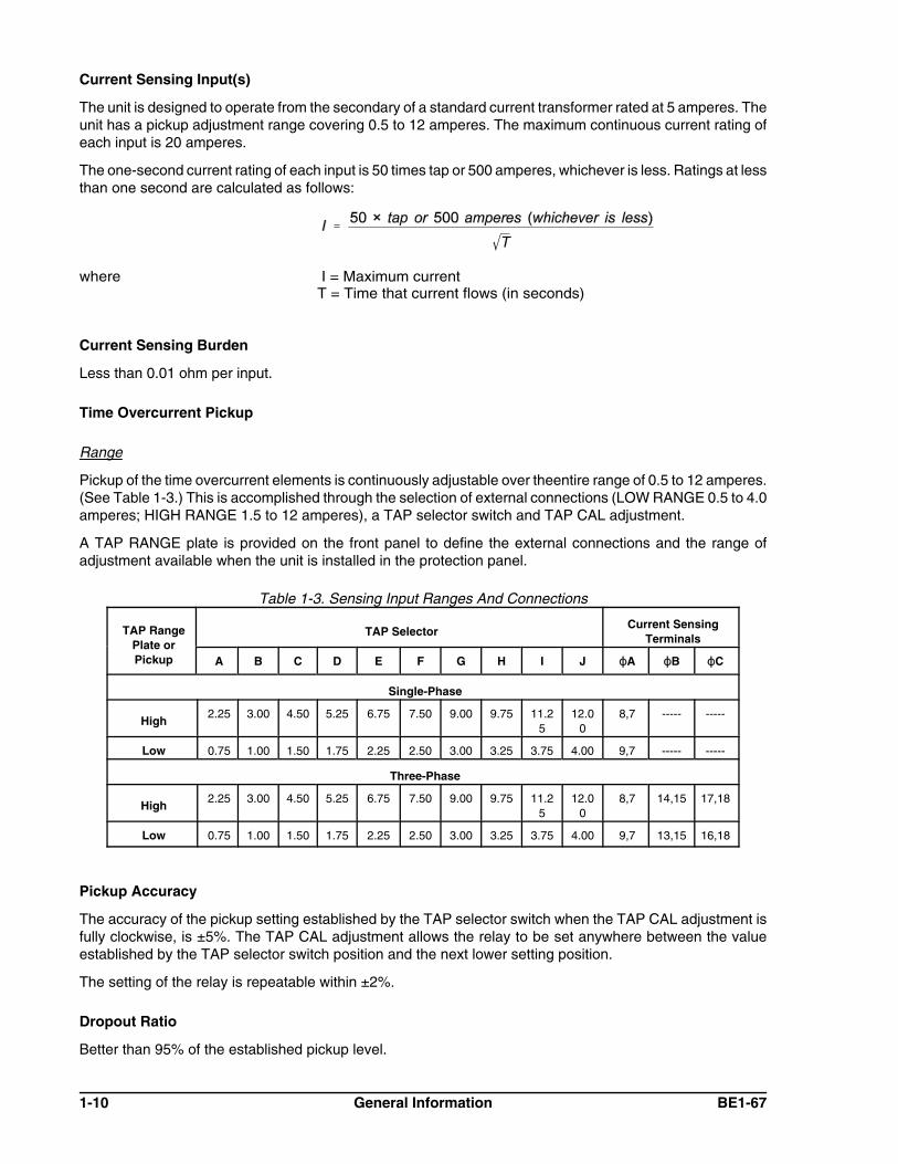
The unit is designed to operate from the secondary of a standard current transformer rated at 5 amperes. Theunit has a pickup adjustment range covering 0.5 to 12 amperes. The maximum continuous current rating ofeach input is 20 amperes.
The one-second current rating of each input is 50 times tap or 500 amperes, whichever is less. Ratings at lessthan one second are calculated as follows:
where I = Maximum currentT = Time that current flows (in seconds)
Current Sensing Burden
Less than 0.01 ohm per input.
Time Overcurrent Pickup
Range
Pickup of the time overcurrent elements is continuously adjustable over theentire range of 0.5 to 12 amperes.(See Table 1-3.) This is accomplished through the selection of external connections (LOW RANGE 0.5 to 4.0amperes; HIGH RANGE 1.5 to 12 amperes), a TAP selector switch and TAP CAL adjustment.
A TAP RANGE plate is provided on the front panel to define the external connections and the range ofadjustment available when the unit is installed in the protection panel.
Table 1-3. Sensing Input Ranges And Connections
TAP RangePlate orPickup
TAP SelectorCurrent Sensing
Terminals
A B C D E F G H I J NA NB NC
Single-Phase
High2.25 3.00 4.50 5.25 6.75 7.50 9.00 9.75 11.2
512.0
08,7 ----- -----
Low 0.75 1.00 1.50 1.75 2.25 2.50 3.00 3.25 3.75 4.00 9,7 ----- -----
Three-Phase
High2.25 3.00 4.50 5.25 6.75 7.50 9.00 9.75 11.2
512.0
08,7 14,15 17,18
Low 0.75 1.00 1.50 1.75 2.25 2.50 3.00 3.25 3.75 4.00 9,7 13,15 16,18
Pickup Accuracy
The accuracy of the pickup setting established by the TAP selector switch when the TAP CAL adjustment isfully clockwise, is ±5%. The TAP CAL adjustment allows the relay to be set anywhere between the valueestablished by the TAP selector switch position and the next lower setting position.
The setting of the relay is repeatable within ±2%.
Dropout Ratio
Better than 95% of the established pickup level.

BE1-67 General Information 1-11
Figure 1-10. Typical Instantaneous Response Time
Timing Characteristics
The relay includes a choice of characteristics. A two-character designation within the style number definesthe timing characteristic. (See Table 1-4.)
Table 1-4. Characteristic Curves and Switch Positions
Switch PositionFor Z2 Option
CharacteristicCurve Characteristic Description
DrawingNumber
3 B1 Short Inverse 99-0932
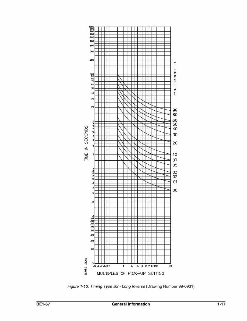
1 B2 Long Inverse 99-0931
5 B3 Definite 99-0933
2 B4 Moderately Inverse 99-0930
4 B5 Inverse 99-0929
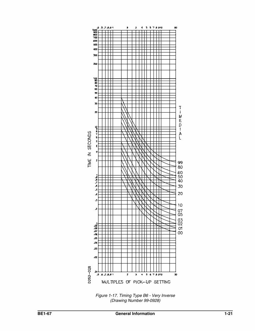
6 B6 Very Inverse 99-0928
7 B7 Extremely Inverse 99-0927
8 E2 Long Inverse (BS 142) 99-1093
9 E4 Inverse (1.3 Sec.) (BS 142) 99-1094
A E5 Inverse (2.9 Sec.) (BS 142) 99-1095
B E6 Very Inverse (BS 142) 99-1096
C, D, E, F E7 Extremely Inverse (BS 142) 99-1097
Time Delay Accuracy
The time delay of the time overcurrent element is within ±5 percent or 50 milliseconds (whichever is greater)of the characteristic curves for any combination of TIME DIAL, TAP and TAP CAL settings at 25°C.
Instantaneous Overcurrent
Pickup Range
Continuously adjustable over the range of one to 40 times the pickup setting established for the timeovercurrent element.
Response Time

1-12 General Information BE1-67
Figure 1-11. Characteristic Angle
Pickup Accuracy
The setting of the relay is repeatable within ±2 percent.
Dropout Ratio
The dropout ratio is better than 92 percent of the established pickup level.
Voltage Sensing Inputs
The continuous rating of these inputs are 240 Vac.
Voltage Sensing Burden
The voltage sensing burden is greater than 25 kilo-ohm at 120 Vac per input.
Directional Unit
The polarizing for the directional unit is derived by the phase relationship between the measured phase current(A) and the sensed quadrature voltage (b-c). The directional element defines a region as shown in Figure 1-11for which tripping will be allowed. The characteristic angle of the relay is defined as the angle between Iz andits ordinate, I. Note that Iz is normal to the characteristic boundary. Resolution of direction requires less than1 cycle.
Sensitivity
Proper directional decisions are assured when the current applied to the relay exceeds 25% of TAP value andthe voltage exceeds 1.0 Vac at the setting of the characteristic angle. When polarizing voltage is less than the1.0 Vac threshold, relay operation will be inhibited.
Characteristic Angle
Adjustment
The BE1-67 is available with two types of adjustment for the characteristic angle.

BE1-67 General Information 1-13
(a) Continuously adjustable over the range of 0 to 90°
(b ) Switch selectable settings of 30°, 45°, 60° and 75°
Repeatability
Repeatability is ±5° from the setting at nominal system frequency.
Limited Range of Operation (Optional)
The front panel control is continuously adjustable over the range of +5°to +90°. The total individual angle ofthe Limited Range of Operation will accordingly vary from 10° to 180°.
Frequency Range
The unit is designed to operate on power systems with a nominal frequency of either 50 or 60 hertz. The unithas been type-tested for proper operation over the frequency range of 45 to 55 hertz for 50 hertz systems and55 to 65 hertz for 60 hertz systems.
Power Supply
Power for the internal circuitry may be derived from a variety of ac or dc external power sources as indicatedin Table 1-5.
Table 1-5. Power Supply Specifications
TypeNominal
InputVoltage
InputVoltageRange
Burdenat
Nominal
K 48 Vdc 24 to 60 Vdc 7.0 W
J 125 Vdc120 Vac
62 to 150 Vdc90 to 132 Vac
10.0 W20.0 VA
*L 24 Vdc 12 to 32 Vdc 7.0 W
†Y 48 Vdc125 Vdc
24 to 60 Vdc62 to 150 Vdc
7.0 W7.5 W
Z 250 Vdc230 Vac
140 to 280 Vdc190 to 270 Vac
8.5 W22.0 VA
NOTES: All references are at 50/60 Hz.* Type L Power Supply may require 14 Vdc to begin operation. Once operating, the
voltage may be reduced to 12 Vdc.† Type Y Power Supply is field-selectable for 48 or 125 Vdc. Selection must be implemented
at time of installation. This power supply option is factory set for 125 Vdc.
Target Indicators
Function targets may be specified as either internally operated or current operated by a minimum of 0.2amperes through the output trip circuit. When current operated, the output circuit must be limited to 30amperes for 0.2 seconds, 7 amperes for 2 minutes and 3 amperes continuously.
Single-Phase Units
When specified by the style number, either an internally operated or a current operated target will be suppliedfor each of the tripping outputs included within the relay (i.e., the time and instantaneous overcurrentfunctions).

1-14 General Information BE1-67
Three-Phase Units
When targets are specified by the style number, internally operated targets are included to indicate the phaseelements (A, B, C) involved in the tripping of the relay. Additionally, either internally operated or currentoperated targets (as selected) indicate the function (time or instantaneous) that caused tripping.
Output Circuits
Output contacts are rated as follows:
Resistive
120/240 Vac Make 30 amperes for 0.2 seconds, carry 7 amperes continuously and break at 7amperes.
250 Vdc Make and carry 30 amperes for 0.2 seconds, carry 7 amperes continuously and breakat 0.3 amperes.
500 Vdc Make and carry 15 amperes for 0.2 seconds, carry 7 amperes continuously and breakat 0.1 amperes.
Inductive
120/240 Vac, Make and carry 30 amperes for 0.2 seconds, carry 7 amperes continuously and 125/250 Vdc break at 0.3 amperes. (L/R = 0.04).
Isolation
In accordance with IEC 255-5 and ANSI/IEEE C37.90, one minute dielectric (high potential) tests as follows:
All circuits to ground: 2,121 VdcInput to output circuits: 1,500 Vac or 2,121 Vdc
UL Recognized
UL recognized per Standard 508, UL File No. E97033. Note: Output contacts are not UL recognized forvoltages greater than 250 volts.
Surge Withstand Capability
Qualified to ANSI/IEEE C37.90.1-1989, Standard Surge Withstand Capability (SWC) Tests for ProtectiveRelays and Relay Systems.
Operating Temperature
The operating temperature range is from -40°C (-40°F) to +70°C (+158°F).
Storage Temperature
The storage temperature range is from -65°C (-85°F) to +100°C (+212°F).
Shock
In standard tests, the relay has withstood 15 g in each of three mutually perpendicular planes withoutstructural damage or degradation of performance.
Vibration
In standard tests, the relay has withstood 2 g in each of three mutually perpendicular planes, swept over therange of 10 to 500 Hz for a total of six sweeps, 15 minutes each sweep without structural damage ordegradation of performance.

BE1-67 General Information 1-15
CHARACTERISTIC CURVES
Figures 1-12 through 1-23 illustrate the characteristic curves that are programmed into the nonvolatile memoryof this relay. To order full-size drawings of these characteristic curves, contact Customer Service Departmentof the Power Systems Group, Basler Electric and request publication number 9 1907 00 999. This publicationcontains nine full size (10 inch x 12 inch) characteristic curves on transparent paper (vellum). A drawingnumber is given under each graph. Use this number to order one specific full-size chart.

1-16 General Information BE1-67
Figure 1-12. Timing Type B1 - Short Inverse(Drawing Number 99-0932)
BE1-67 General Information 1-17
Figure 1-13. Timing Type B2 - Long Inverse (Drawing Number 99-0931)

1-18 General Information BE1-67
Figure 1-14. Timing Type B3 - Definite Time (Drawing Number 99-0933)

BE1-67 General Information 1-19
Figure 1-15. Timing Type B4 - Moderate Inverse(Drawing Number 99-0930)

1-20 General Information BE1-67
Figure 1-16. Timing Type B5 - Inverse(Drawing Number 99-0929)
BE1-67 General Information 1-21
Figure 1-17. Timing Type B6 - Very Inverse(Drawing Number 99-0928)

1-22 General Information BE1-67
Figure 1-18. Timing Type B7 - Extremely Inverse(Drawing Number 99-0927)

BE1-67 General Information 1-23
Figure 1-19. Timing Type E2 - BS-142 Long Inverse(Drawing Number 99-1093)

1-24 General Information BE1-67
Figure 1-20. Timing Type E4 - BS-132 Inverse(Drawing Number 99-1094)

BE1-67 General Information 1-25
Figure 1-21. Timing Type E5 - BS-142 Inverse(Drawing Number 99-1095)

1-26 General Information BE1-67
Figure 1-22. Timing Type E6 - BS-142 Very Inverse(Drawing Number 99-1096)

BE1-67 General Information 1-27
Figure 1-23. Timing Type E7 - BS-142 Extremely Inverse(Drawing Number 99-1097)

BE1-67 Human-Machine Interface 2-1
SECTION 2 HUMAN-MACHINE INTERFACETable 2-1. BE1-67 Controls and Indicators (refer to Figures 2-1, 2-2 and 2-3)
Locator Control Or Indicator Function
A CHARACTERISTICANGLE
This potentiometer (options 3-1, 3-3, 3-5 or 3-6 ) or 4-positionswitch (options 3-2 and 3-4) defines the characteristic angle forthe directional element of the relay.
This potentiometer can adjust the characteristic angle alpha overthe range of 0° to 90° while the 4- position switch can set thecharacteristic angle to 30°, 45°, 60° or 75°. When thepotentiometer is knob controlled (as in Figure 2-1), the max CWposition represents the minimum characteristic angle (or 0°).When the potentiometer is a screwdriver-operated multi-turnpotentiometer (as in Figure 2-2), the max CW position representsthe maximum characteristic angle (or 90°).
B TAP Selector This 10-position rotary switch provides the primary means ofsetting the pickup for the overcurrent functions of the relay. Whenthe TAP CAL control (locator K) is in the full clockwise position,the pickup of the relay is based on the setting of the TAP selectorswitch. The setting for the time overcurrent function is the valuedefined by the switch position (A to J) and the externalconnections (HIGH/LOW tap range).
This control, together with the TAP CAL control, establishes thepickup level of all phases monitored by the relay. Note that it issafe to switch the TAP selector without disconnecting the sensingcurrent.
C TAP RANGE Plate This plate is adjusted to indicate HIGH or LOW, the setting rangecorresponding to the connections on the back of the relay.
D POWER Indicator A red LED is lit when the relay power supply is functioning. Thisprovides a front panel indication of the relay status. An optionalPOWER SUPPLY STATUS ALARM contact (Options 3-3 and 3-4) is available to provide a remote indication of this condition.
E FUNCTION Targets These magnetically latched indicators change from black toorange when the corresponding TIME overcurrent or INST(instantaneous) overcurrent function causes the trip output relaysto be energized or current to flow through the output contacts.
F TARGET RESET Lever This lever engages the reset mechanism behind the relay cover.When raised up, this lever resets the magnetically latchedtarget(s).

2-2 Human-Machine Interface BE1-67
Figure 2-1. BE1-67, Three-Phase Relay With Characteristic Angle Control Knob

BE1-67 Human-Machine Interface 2-3
Figure 2-2. BE1-67, Three-Phase Relay With Characteristic Angle and Limited Region Of Operation
2-4 Human-Machine Interface BE1-67
Table 2-1. BE1-67 Controls and Indicators (refer to Figures 2-1, 2-2 and 2-3) - continued
Locator Control Or Indicator Function
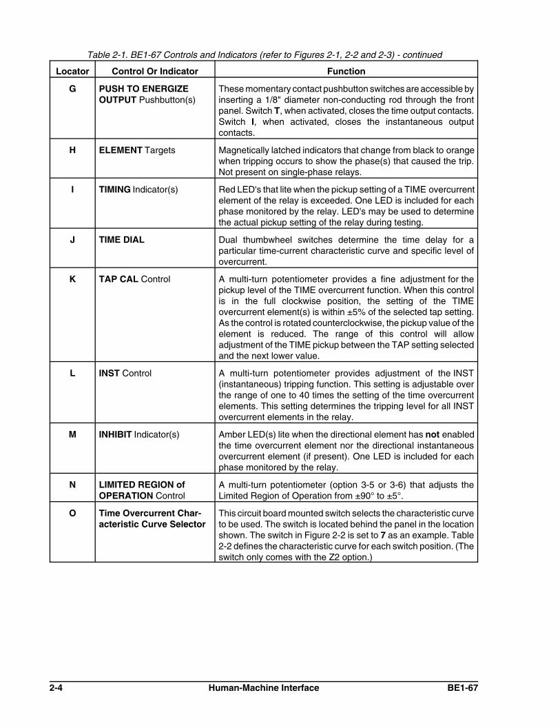
G PUSH TO ENERGIZEOUTPUT Pushbutton(s)
These momentary contact pushbutton switches are accessible byinserting a 1/8" diameter non-conducting rod through the frontpanel. Switch T, when activated, closes the time output contacts.Switch I, when activated, closes the instantaneous outputcontacts.
H ELEMENT Targets Magnetically latched indicators that change from black to orangewhen tripping occurs to show the phase(s) that caused the trip.Not present on single-phase relays.
I TIMING Indicator(s) Red LED's that lite when the pickup setting of a TIME overcurrentelement of the relay is exceeded. One LED is included for eachphase monitored by the relay. LED's may be used to determinethe actual pickup setting of the relay during testing.
J TIME DIAL Dual thumbwheel switches determine the time delay for aparticular time-current characteristic curve and specific level ofovercurrent.
K TAP CAL Control A multi-turn potentiometer provides a fine adjustment for thepickup level of the TIME overcurrent function. When this controlis in the full clockwise position, the setting of the TIMEovercurrent element(s) is within ±5% of the selected tap setting.As the control is rotated counterclockwise, the pickup value of theelement is reduced. The range of this control will allowadjustment of the TIME pickup between the TAP setting selectedand the next lower value.
L INST Control A multi-turn potentiometer provides adjustment of the INST(instantaneous) tripping function. This setting is adjustable overthe range of one to 40 times the setting of the time overcurrentelements. This setting determines the tripping level for all INSTovercurrent elements in the relay.
M INHIBIT Indicator(s) Amber LED(s) lite when the directional element has not enabledthe time overcurrent element nor the directional instantaneousovercurrent element (if present). One LED is included for eachphase monitored by the relay.
N LIMITED REGION ofOPERATION Control
A multi-turn potentiometer (option 3-5 or 3-6) that adjusts theLimited Region of Operation from ±90° to ±5°.
O Time Overcurrent Char-acteristic Curve Selector
This circuit board mounted switch selects the characteristic curveto be used. The switch is located behind the panel in the locationshown. The switch in Figure 2-2 is set to 7 as an example. Table2-2 defines the characteristic curve for each switch position. (Theswitch only comes with the Z2 option.)

Table 2-1. BE1-67 Controls and Indicators (refer to Figures 2-1, 2-2 and 2-3) - continued
Locator Control Or Indicator Function
BE1-67 Human-Machine Interface 2-5
CAUTIONThis switch must be in the normal (N) position for properoperation of the relay.
P N/T (Normal/Test) Switch This slide switch (shown in Figure 2-3) is mounted on the side ofthe digital board. This permits a technician to access a series ofstored diagnostic routines to validate the calibration of the relayand to test and troubleshoot the device on the bench.
Table 2-2. Timing Curve Selection
Timing TypeSelectorPosition
Ref. FigureNumber
Bl Short Inverse 3 1-12
B2 Long Inverse 1 1-13
B3 Definite Time 5 1-14
B4 Moderately Inverse 2 1-15
B5 Inverse 4 1-16
B6 Very Inverse 6 1-17
B7 Extremely Inverse 7 1-18
E2 BS142 Long Inverse 8 1-19
E4 BS142 Inverse (1.3 sec) 9 1-20
E BS142 Inverse (2.9 sec) A 1-21
E6 BS142 Very Inverse B 1-22
E7 BS142 Extremely Inverse C, D, E, F 1-23

2-6 Human-Machine Interface BE1-67
Figure 2-3. Location of Assemblies, Controls and Indicators

BE1-67 Functional Description 3-1
SECTION 3 FUNCTIONAL DESCRIPTION
GENERAL
BE1-67 Phase Directional Overcurrent Relays are microprocessor based time overcurrent relays withdirectional supervision. This allows the relay to be more effectively coordinated for the protection oftransmission and distribution circuits. Figure 3-1 is a BE1-67 relay functional block diagram and illustrates theoverall operation of the relay.
Figure 3-1. Functional Block Diagram
INPUT CIRCUITS
BE1-67 relays may be configured to sense either a single-phase current and a phase-to-phase voltage, orthree -phase currents and three phase-to-phase voltages. (A three-phase unit is illustrated.)
Current Sensing
Internal current sensing transformers are designed to receive their input from the five ampere nominalsecondary of a standard current transformer in the power system. These input transformers are tapped so thatthe range of the relay is determined by the external connections. These connections are defined in Table 3-1.

3-2 Functional Description BE1-67
Table 3-1. Current Sensing Input Connections
Sensing Type Phase
Terminal Numbers
High Range (1.5 to 12 A) Low Range (0.5 to 4 A)
Single-Phase (Type A) - 8 to 7 9 to 7
Three-Phase (Type B)
A 8 to 7 9 to 7
B 14 to 15 13 to 15
C 17 to 18 16 to 18
The output from the sensing input transformers are applied to a scaling circuit that converts each of the inputcurrents to a dc voltage level that can be used within the relay. This scaling is determined by the TAP SELECTswitch and the TAP CAL control on the front of the relay. These controls adjust the scaling for all of the currentinputs at one time. In the three-phase relay, this eliminates the requirement for three separate calibrations,one for each phase.
The TAP SELECT switch is a ten-position rotary switch that selects one of the current ranges shown in Table3-2. The TAP CAL control changes these ranges when the control is moved from the maximum clockwiseposition. HIGH and LOW range is determined by the connections made to the relay inputs. When the TAPCAL control is fully clockwise, the pickup setting of the relay will be within ±5% of the TAP SELECT setting.
Table 3-2. Sensing Input Range and Setting
RangeTAP SELECT Position
A B C D E F G H I J
HIGH 2.25 3.0 4.5 5.25 6.75 7.5 9.0 9.75 11.25 12.0
LOW 0.75 1.0 1.5 1.75 2.25 2.5 3.0 3.25 3.75 4.0
The TAP CAL control provides a means of continuous adjustment between a selected setting of the TAPSELECT and the next lower setting. When the TAP SELECT is set on position A, the TAP CAL control willprovide an adjustment to at least 0.5 A on the LOW range connection and 1.5 A for the HIGH rangeconnection.
Voltage Sensing
Voltage sensing inputs accept nominal 120 Vac phase-to-phase voltages and are configured to match thecurrent sensing type defined by the style number (single-phase or three-phase).
DIRECTIONAL ELEMENT
The directional element determines the direction of the current flow by monitoring the angular phaserelationship between phase current and the corresponding quadrature phase-to-phase voltage (phase Acurrent and b-c voltage). The CHARACTERISTIC ANGLE adjustment and (optional) LIMITED REGION oFOPERATION adjustment are front-panel potentiometer controls that are described in the following paragraphs.
Characteristic Angle
The CHARACTERISTIC ANGLE adjustment controls the characteristic angle (alpha) shown in Figure 3-2.This rotates the characteristic angle of the directional unit so that the maximum sensitivity can match theimpedance angle of the protected line. The tripping characteristic of the relay is then defined by a line, thatis, perpendicular to IZ. Note that the slight bow in this boundary about the origin is caused by the minimumsensitivity of the directional element: 0.02 ampere and 1.0 volt.

BE1-67 Functional Description 3-3
Figure 3-2. Characteristic Angle
Two types of CHARACTERISTIC ANGLE controls are available and are specified by the style number. (Referto the option 3 column in Figure 1-9, Style Number Identification Chart.)
1. A potentiometer provides continuous adjustment of the characteristic angle over the range of 0° to +90°.Options 3-1 and 3-3 have a control knob operated potentiometer. Options 3-5 and 3-6 have a screwdriveroperated, multi-turn potentiometer.
2. A four position selector switch provides discrete settings of +300°, +45°, +60° and +75° (Options 3-2 and3-4.)
When the phase relationship between the current(s) and voltage(s) do not meet the criteria of the directionalelement, an inhibit signal is output. This signal illuminates the appropriate PHASE INHIBIT LED on the relayfront panel and prevents the operation of the time overcurrent function in the relay. This signal also inhibitsthe operation of the optional directional instantaneous overcurrent element. The inhibit signals within the relayare provided for each sensed phase.
Limited Region Of Operation
The directional element of the standard relay defines a region for which tripping is allowed. (This is shownas the gray area in Figure 3-2.) This region (angle $ as shown in Figure 3-3) may be reduced by the LIMITEDREGION of OPERATION control (a multi-turn potentiometer accessed through the front panel). The controlis continuously adjustable (with reference to IA in Figure 3-3) from ±5 degrees to ±90 degrees.

3-4 Functional Description BE1-67
Figure 3-3. Limited Region of Operation
INDICATORS
Depending on the options provided, up to five different indicators are visible on the front panel. They are:
! INHIBIT LED's! TIMING LED's! POWER LED! FUNCTION targets! ELEMENT targets
INHIBIT LED's
When the phase relationship between the current(s) and voltage(s) do not meet the criteria of the directionalelement, an inhibit signal is output. This signal lights the appropriate PHASE INHIBIT LED on the relay frontpanel and prevents the operation of the time overcurrent function in the relay. It also inhibits the directionalinstantaneous overcurrent element (optional) operation.
TIMING LED's
Red LED's that light when the pickup setting of a TIME overcurrent element of the relay is exceeded. One LEDis included for each phase monitored by the relay. LED's may be used to determine the actual pickup settingof the relay during testing.
POWER LED's
A red LED lights when the relay power supply is functioning. This provides a front panel indication of the relaystatus.
FUNCTION Targets
These magnetically latched indicators change from black to orange when the corresponding TIME overcurrentor INST (instantaneous) overcurrent function causes the trip output relays to be energized or current to flowthrough the output contacts.
ELEMENT Targets
Magnetically latched indicators that change from black to orange when tripping occurs to show the phase(s)that caused the trip. Not present on single-phase relays.
POWER SUPPLY
Basler Electric enhanced the power supply design for unit case relays. This new design created three, widerange power supplies that replace the four previous power supplies. Style number identifiers for these powersupplies have not been changed so that customers may order the same style numbers that they ordered

BE1-67 Functional Description 3-5
previously. The first newly designed power supplies were installed in unit case relays with EIA date codes9638 (third week of September 1996). A benefit of this new design increases the power supply operatingranges such that the 48/125 volt selector is no longer necessary. Specific voltage ranges for the three newpower supplies and a cross reference to the style number identifiers are shown in Table 3-3.
Table 3-3. Wide Range Power Supply Voltage Ranges
Power Supply Style ChartIdentifiers
Nominal Voltage Voltage Range
Low Range R 24 Vdc 12 * to 32 Vdc
Mid Range O, P, S 48, 125 Vdc,120 Vac
24 to 150 Vdc,90 to 132 Vac
High Range T 125, 250 Vdc,120, 240 Vac
62 to 280 Vdc,90 to 270 Vac
* 14 Vdc is required to start the power supply.
Relay operating power is developed by the wide range, isolated, low burden, fly-back switching, solid statepower supply. Nominal ±12 Vdc is delivered to the relay internal circuitry. Input (source voltage) for the powersupply is not polarity sensitive. A red LED turns ON to indicate that the power supply is functioning properly.
LOGIC CIRCUITS
The logic circuits identified in the block diagram of Figure 3-1 and briefly described in the following paragraphsare intended to show functionally how the BE1-67 relay operates.
Microprocessor
The microprocessor fulfills many of the logic and signal processing functions described in the followingparagraphs and performs all of the time overcurrent computations.
Multiplexor
The multiplexor sequentially switches each of the sensed current inputs to the analog-to-digital converter andlevel detector circuits. (For single-phase relays, the multiplexor is bypassed.)
Analog-to-Digital Converter And Level Detector
When the dc voltage representing the actual sensed current meets or exceeds the selected pickup point, theanalog-to-digital converter supplies a binary value to the trip comparator and scaler circuit and to a counterwithin the microprocessor for calculation of the required time delay.
When the value of a sensed phase current exceeds the PICKUP setting of the relay and the directional unitdoes not inhibit the operation of the time trip comparator, the TIMING LED will be illuminated for that phase.This LED will remain illuminated as long as the sensed phase current exceeds the pickup level set on the relay(representing the time overcurrent function) and the instantaneous overcurrent circuits are applied to theirrespective output driver.
Outputs
Output Drivers
Each output driver supplies the current to energize the associated output relay. Either normally open (OutputE) or normally closed (Output F) contacts may be specified for the relay. All output contacts will be of the sameconfiguration within a given relay. These output contacts may have targets associated with them if so specifiedby the style number.

3-6 Functional Description BE1-67
Push-to-Energize Output Contacts
If option 2-C has been selected, a small pushbutton switch is included for the time overcurrent functions andif present for the instantaneous function. Each switch when depressed will energize the corresponding outputrelay for testing purposes. To prevent accidental operation of these switches, they have been recessed behindthe front panel of the relay and are accessed by inserting a thin non-conducting rod through access holes inthe panel.
Appropriate power must be applied to terminals 3 and 4 (the relay power supply) for these pushbuttons tooperate the output relays. However, it is not necessary to apply currents and voltages to the sensing inputsof the relay for these switches to function.
Power Supply Status Output
The power supply status output relay (option 3-3 and 3-4) has normally closed output contacts. This relay isenergized by the presence of nominal voltage at the output of the power supply. Normal operating voltage thenkeeps the relay continuously energized and the contacts open. However, if the power supply voltage fallsbelow requirements, the power supply status output relay will de-energize and close the contacts.
A shorting bar is included in the relay case so that the status output terminals can provide a remote indicationthat the subject relay has been withdrawn from the case or taken out of service by removing the connectionplug.
This output is not associated with any magnetically latched target. The POWER LED on the relay front panelprovides a visual indication of normal operating status of the power supply.
TARGET INDICATOR CIRCUITS
When the TARGET option is specified as either an A or a B, magnetically latched target indicators areincluded within the relay. Targets are provided for the TIME overcurrent and the optional INST (instantaneous)overcurrent functions. These targets may be actuated by either of two methods as defined by the style numberand explained in the following paragraphs.
Type A targets (referred to as INTERNALLY OPERATED) are operated by an internal driver circuit that isactuated by a signal from the relay internal logic circuits. This type of target is tripped regardless of the currentlevel flowing through the output relay contacts. It is the only type of target that can be supplied if the outputcontacts are specified as normally closed (output F).
Type B targets (referred to as CURRENT OPERATED) are operated when a minimum of 0.2 ampere flowsthrough the relay output contacts. To accomplish this, a special reed relay is placed in series with the outputcontacts to provide the necessary signal to the target indicator. (The series impedance of the reed relay is lessthan 0.1 ohm.)
Each target indicator is visible on the front panel of the relay with the cover in place. When operated, the discin the target changes from black to red and is magnetically latched in this position. To reset the target afteran abnormal system condition has been cleared, manually raise the target reset level on the front of the relayor in the lower portion of the cover.
When targets are specified on single-phase relays (sensing input type A) only TIME and INST (instantaneous)FUNCTION targets are provided. These targets may be either type A or type B.
Three-phase (Sensing Input type B) relays are supplied, when specified, with FUNCTION (TIME and INST)targets and ELEMENT targets (A, B, C). The FUNCTION targets are either type A or type B as specified bythe style number. The ELEMENT targets are always type A (internally operated) targets.

BE1-67 Installation 4-1
SECTION 4 INSTALLATION
GENERAL
When not shipped as part of a control or switchgear panel, BE1-67, Phase Directional Overcurrent Relays areshipped in sturdy cartons to prevent damage during transit. Immediately upon receipt, check the model andstyle number against the requisition and packing list to see that they agree. Visually inspect the relay fordamage that may have occurred during shipment. If there is evident damage, immediately file a claim with thecarrier and contact a sales representative at Basler Electric, Highland, Illinois.
In the event the unit is not to be installed immediately, store it in its original shipping carton in a moisture anddust-free environment. It is strongly recommended that an operational test (Section 5) be performed prior toinstallation.
OPERATING PRECAUTIONS
Before installation or operation, observe the following precautions:
1. Always be sure that external operating (monitored) conditions are stable before removing a BE1-67,Phase Directional Overcurrent Relay, for inspection, testing or servicing.
2. To avoid false tripping when removing connection plugs, always remove the lower connection plug first.To avoid false tripping when inserting connection plugs, always insert the lower connection plug last.
3. BE1-67, Phase Directional Overcurrent Relays, are solid-state devices and have been type tested inaccordance with the requirements defined in the following paragraph, Dielectric Test. If a wiring insulationtest is required on the switchgear or panel assembly of which these units are a part, observe the NOTESin the following paragraph.
4. Be sure that the BE1-67, Phase Directional Overcurrent Relay, case is hard-wired to earth ground usingthe ground terminal (TB2-1) on the rear of the unit.
5. When the unit is in service, the controls should be protected by the plastic cover supplied. This limitsaccess to the control settings.
DIELECTRIC TEST
In accordance with IEC 255-5 and ANSI/IEEE C37.90, one minute dielectric (high potential) tests may beperformed as follows:
All circuits to ground: 2,121 VdcInput to output circuits: 1,500 Vac or 2,121 Vdc
MOUNTING
Because the relay is of solid state design, it does not have to be mounted vertically. Any convenient mountingangle may be chosen. Relay outline dimensions and panel drilling diagrams are provided in Figures 4-1through 4-6.

4-2 Installation BE1-67
Figure 4-1. Outline Dimensions, Front View

BE1-67 Installation 4-3
Figure 4-2. Outline Dimensions, Rear View

4-4 Installation BE1-67
Figure 4-3. Outline Dimensions, Side View — Semi-Flush Mounting

BE1-67 Installation 4-5
Figure 4-4. Outline Dimensions, Side View — Projection Mounting

4-6 Installation BE1-67
Figure 4-5. Panel Drilling Diagram — Semi-Flush Mounting

BE1-67 Installation 4-7
Figure 4-6. Panel Drilling Diagram — Projection Mounting

4-8 Installation BE1-67
NOTEBe sure the relay case is hard-wired to earth ground with no smaller than 12 AWG copperwire attached to the ground terminal on the rear of the relay case. When the relay isconfigured in a system with other protective devices, it is recommended to use a separatelead to the ground bus from each relay.
CONNECTIONS
Incorrect wiring may result in damage to the relay. Be sure to check the model and style number of the relaybefore connecting and energizing the particular relay.
Except as noted above, connections should be made with minimum wire size of 14 AWG. The followingillustrations provide information on relay connections.
! Control circuit connections are shown in Figure 4-7.
! Typical ac connections for single-phase relays are shown in Figure 4-8.
! Typical ac connections for three-phase relays are shown in Figure 4-9.
! Internal connections are shown in Figures 4-10 and 4-11.
Figure 4-7. DC Control Connections

BE1-67 Installation 4-9
Figure 4-8. Single-Phase AC Connections

4-10 Installation BE1-67
Figure 4-9. Three-Phase AC Connections

BE1-67 Installation 4-11
Figure 4-10. BE1-67 Single-Phase, Internal Connection Diagram

4-12 Installation BE1-67
Figure 4-11. BE1-67 Three-Phase, Internal Connection Diagram

BE1-67 Testing 5-1
NOTEAdjustments for TAP CAL and INST (instantaneous) are multi-turn potentiometers andrequire a minimum of 15 turns from full CW to full CCW.
SECTION 5 TESTING
GENERAL
The various test procedures that follow are intended to verify operation, to set pickup and time delay, and toset the characteristic angle of the relay for a specific application. Each phase of a three-phase relay may betested as a separate single-phase device using the procedures provided.
When test results do not fall within the specified tolerances, the following should be considered:
1. Tolerance of the test equipment used
2. Cycle-to-cycle phase stability of the test equipment
3. Tolerances of any external components used in the test setup
Equipment Required
The current source used in the verification testing should have the following capabilities:
a. Current output needs to be switchable from a set position to an operate position. This allows the relaysensing circuits to see a current change from an initial current to a set (test) value.
b. The current source needs to be capable of delivering at least 20 amperes (5 VA). This is necessary to testthe full capability of the instantaneous overcurrent element.
c. Because the current levels used to verify the operation of the instantaneous overcurrent element mayexceed the continuous current rating of the relay, it is suggested that the current source include provisionfor automatic removal of the test current following a trip.
Preliminary Setup
Step 1. With the connection plug(s) removed (always remove lower connection plug first and insert last),connect the unit as shown in Figure 5-1 for a single phase unit (sensing input type A) or Figure 5-2for a three-phase unit (sensing input type B).
Step 2. Adjust the TAP CAL control fully CW.
Step 3. Adjust the time dial to 99.
Step 4. Adjust the TAP SELECT switch to position A.
Step 5. Adjust the INST (instantaneous) control (if present) fully CW.
Step 6. Adjust the CHARACTERISTIC ANGLE to the minimum setting position (0° for the continuouslyadjustable option, or 30° for the switch selectable type).
Step 7. Verify that the proper power supply voltage is connected to the relay case. (Refer to Table 1-5 forthe ranges of each supply.)
Step 8. Insert the relay connection plug(s). (Always insert the lower connection plug last.)
Step 9. Verify that the power supply LED indicator is on and, if installed, that the power supply statuscontact (terminals 19 and 20 ) is open.
Step 10. If there is a LIMITED RANGE OF OPERATION control in the relay (option 3-5 or 3-6), it isnecessary to set this control to an angle of 91°.

5-2 Testing BE1-67
NOTEIn order to have a 180° angle as the trip direction (90° or either side of the torque anglevector), it is necessary to set the LIMITED RANGE OF OPERATION control to 91°.
To adjust it to an angle of 91°, adjust the voltage source to 120 Vac at a phase angle of 0°. Adjustthe input current source to 1.0 ampere (LOW range) or 3.0 ampere (HIGH range) and at a phaseangle of -1°. Then, starting from the maximum CW position, slowly rotate the LIMITED REGION OFOPERATION control CCW until the INHIBIT LED just lights.
Step 11. Insure that the TEST/NORMAL switch (callout P of Figure 2-3) is in the NORMAL position.
Figure 5-1. Single-Phase Test Setup

BE1-67 Testing 5-3
Figure 5-2. 3-Phase Test Setup
VERIFICATION TESTING
This procedure verifies the operation of the unit. Check Figure 1-9, Style Number Identification Chart, for thestyle number of the relay to identify the options included within the specific relay to be tested.
Time Overcurrent Pickup Test
Step 1. After performing the preliminary setup, adjust the input voltage source for 120 Vac at a phase angleof 0°.
Step 2. Adjust the input current source for 0.5 ampere (LOW range) or 1.5 amperes (HIGH range) at aphase angle of +90° (90° leading). The INHIBIT LED indicator of the phase under test should beextinguished. If not, current or voltage connections are reversed and should be corrected.
Step 3. Slowly turn the TAP CAL control CCW until the (associated phase) TIMING LED lights. This verifiesthe minimum pickup point of the specified range.

5-4 Testing BE1-67
NOTEIt is permissible to change the TAP SELECT switch position without disconnecting thecurrent sensing inputs.
Step 4. Turn the TAP CAL control fully CW. The TIMING LED should extinguish. Slowly increase themagnitude of the input current to a level where the TIMING LED again lights. Observe the inputcurrent level. This value should be within ±5% of 0.75 ampere (LOW range) or 2.25 amperes (HIGHrange). This verifies the pickup accuracy of the TAP A setting.
Step 5 . If verification of the remaining TAP SELECT positions is desired, adjust the TAP SELECT to its nextCW position. Then slowly increase the magnitude of the input current to a level where the TIMINGLED again lights. Observe that the current level is within ±5% of the value in Table 5-1.
Table 5-1. Pickup Values At Indicated TAP SELECT Position
Range A B C D E F G H I J
HIGH 2.25 3.0 4.5 5.25 6.75 7.5 9.0 9.75 11.25 12.0
LOW 0.75 1.0 1.5 1.75 2.25 2.5 3.0 3.25 3.75 4.0
Step 6. If a 3-phase unit is being tested, phase B and phase C inputs may be tested by repeating Steps 1through 5 using the inputs as shown in Figure 5-2.
Instantaneous Overcurrent Pickup Test
Step 1. Perform the preliminary test setup.
Step 2. Adjust the INST control fully CCW.
Step 3. If the directional instantaneous option has been selected (option 1-3), adjust the voltage source toapply 120 Vac at a phase angle of 0°.
Step 4. Adjust the sensing current level for 0.75 amperes at 90° leading. Apply this current to the sensinginput(s) of the relay. Confirm that the instantaneous output has been energized. (Terminals 2 to 10will show continuity if the relay has been supplied with NO (type E) outputs and no continuity if therelay has been supplied with NC (type F) outputs.) This step also verifies the low end of the one to40 times pickup setting of the instantaneous overcurrent setting range.
Step 5. Adjust the sensing current level for 0.5 ampere. Adjust the TAP CAL control CCW until the TIMINGLED(s) light. Adjust the sensing current for a level of 20 amperes. Rotate the INST control fully CW.Then adjust CCW until the instantaneous output has been energized. (Terminals 2 to 10 will showcontinuity if the relay has been supplied with NO (type E) outputs and no continuity if the relay hasbeen supplied with NC (type F) outputs.) This verifies the high end of the one to 40 times pickupsetting of the instantaneous overcurrent setting range.
Directional Verification
For the following tests, it is necessary to adjust and monitor the magnitude of the voltage(s) and current(s) aswell as the phase angle relationship between these sensing quantities. It may be useful to record the resultson polar graph paper to more clearly understand the significance of the results. Blank forms for this purposeare furnished as Figures 5-3 and 5-4.

BE1-67 Testing 5-5
Figure 5-3. Blank Polar Graph Form
Figure 5-4. Blank Polar Graph Form

5-6 Testing BE1-67
In the polar graphs associated with theprocedures for Directional Verification:
I = Measured current at unity power factorIZ = Fault currentV = Quadrature or polarizing voltage
Figure 5-5. " = 0°
There are two types of CHARACTERISTIC ANGLE adjustments available with this unit:
(1) A potentiometer capable of adjusting this angle over the range of 0° to 90°.
(2) A 4-position switch with settings of 30°, 45°, 60° and 75°.
If a potentiometer is provided, use Procedure 1. If a switch is supplied, use Procedure 2 .
Procedure 1
(For use with continuously adjustable CHARACTERISTIC ANGLE, options 3-1, 3-3, 3-5, and 3-6.)
Step 1. Perform the preliminary setup.
Step 2. Adjust the input voltage source for 120 volts ata phase angle of 0°.
Step 3 . Adjust the input current Source for 1.0 amperes(LOW range ) or 3.0 amperes (HIGH range) at a phase angle of +90° (90° leading).
Result: The INHIBIT LED indicator should be extinguished and the (appropriate phase) timing LEDOFF. If not, the current or voltage connections are reversed and should be corrected.
Step 4. Vary the phase angle ofthe input current through360° and record the phaseangles within which theINHIBIT LED is OFF.When shown on a polarplot, the result should be astraight line (through theorigin) from 0° to 180° ±5°.This plot defines the tripregion as shown in Figure5-5. The trip region isshown as the lightlyshaded area and thetolerance region as themore densely shadedregion.
Step 5. Rotate the CHARAC-TERISTIC ANGLE controlto the maximum setting.
Step 6. Vary the phase angle ofthe input current through360° and record the phaseangles within which theINHIBIT LED is OFF.When shown on a polarplot, the result should be astraight line (through theorigin ) from -90° to +90°±5°. This plot defines thetrip region as shown inFigure 5-6.

BE1-67 Testing 5-7
Figure 5-6. " = 90°
Figure 5-7. Minimum Region Of Operation
Step 7. (Only when option 3-5 or 3-6 is present.) Rotate theLIMITED REGION OFO P E R A T I O Npotentiometer fully CCW.
Step 8. Vary the phase angle of theinput current through 360°and record the phaseangles within which theINHIBIT LED is OFF.When shown on a polarplot, the result should benarrowed down to anincluded angle # 10°(shown as the shadedregion in Figure 5-7).

5-8 Testing BE1-67
Figure 5-8. " = 30°
Figure 5-9. " = 45°
Procedure 2
(For use with switch selectable CHARACTERISTIC ANGLE, options 3-2 and 3-4.)
Step 1. Perform the preliminarysetup.
Step 2. Turn the CHARACTER-ISTIC ANGLE switch to30°.
Step 3. Adjust the input voltagesource for 120 Vac at aphase angle of 0°.
Step 4. Adjust the input currentsource for 1.0 ampere(LOW range ) or 3.0amperes (HIGH range) at aphase angle of +90° (90°leading). The INHIBIT LEDindicator should be OFF,and the TIMING LED ON(i.e., the appropriate phaseLEDs thereof on a 3-phaseunit). If not, current orvoltage connections arereversed and should becorrected.
Step 5. Vary the phase angle of theinput current through 360°and record the phaseangles at which theINHIBIT LED is OFF. Whenshown on a polar plot, theresult should be a straightline (through the origin )from -30° to +150° ±5°.This plot defines the tripregion as shown in Figure5-8.
Step 6. Adjust the CHARACTER-ISTIC ANGLE control to asetting of 45°.
Step 7. Vary the phase angle of theinput current through 360°and record the phaseangles within which theINHIBIT LED is OFF. Whenshown on a polar plot, theresult should be a straightline (through the origin)from -45° to +135° ±5°.This plot defines the trip region as shown in Figure 5-9.

BE1-67 Testing 5-9
Figure 5-10. " = 60°
Figure 5-11. " = 75°
Step 8. Adjust the CHARACTER-ISTIC ANGLE switch to60°.
Step 9. Vary the phase angle ofthe input current through360° and record the phaseangles within which theINHIBIT LED is OFF.When shown on a polarplot, the result should be astraight line (through theorigin) from a -60° to +120°±5°. This plot defines thetrip region as shown inFigure 5-10.
Step 10. A d j u s t t h e C H A R -ACTERISTIC ANGLEcontrol to a setting of 75°.
Step 11. Vary the phase angle ofthe input current through360° and record the phaseangles within which theINHIBIT LED is OFF.When shown on a polarplot, the result should be astraight line (through theorigin) from -75° to +105°±5°. This plot defines thetrip region as shown inFigure 5-11.

5-10 Testing BE1-67
TIMING CURVE VERIFICATION
There are many timing characteristics available for BE1-67 relays. Table 5-2 provides two checkpoints foreach of the twelve timing characteristic curve types.
The characteristic included within the relay is defined in the style number by a two-character code. If this codeis B1 to B7, E2, or E4 to E7, only one characteristic can be tested. If the code is Z2, the characteristic desiredwill need to be selected by the TIME OVERCURRENT CHARACTERISTIC CURVE SELECTOR switchlocated behind the front panel of the relay. (Refer to Figure 2-3 for switch location.) Table 5-2 defines theposition of this selector for the desired characteristic.
Table 5-2. Expected Timing Values At Five Times Pickup
TIMINGTYPE
Z2 OptionSelectorPosition
Expected Times at Indicated Time Dial Setting* (in seconds)
00 10
B1 3 0.066 0.194
B2 1 0.587 3.41
B3 5 0.103 0.494
B4 2 0.168 0.875
B5 4 0.149 0.722
B6 6 0.126 0.551
B7 7 0.195 1.011
E2 8 1.56 9.06
E4 9 0.13 0.54
E5 A 0.233 1.190
E6 B 0.16 0.77
E7 C, D, E, F 0.13 0.48
NOTE: Accuracy, with the TAP CAL control rotated fully CW, is ±5% or 50 milliseconds (whichever isgreater) within the values shown graphically on the published characteristic curves.
Verification of the timing may be performed at a low current level for convenience. Connect the relay as shownin Figure 5-1 or 5-2. In the following steps, the timing will be measured from the point that the sensed currentis applied until the output contact is energized. The equipment to accomplish this task will need to step from0 to 3.75 amperes (if the relay is connected for LOW range) or 11.25 amperes (if the relay is connected forHIGH range).
Step 1. Set the TAP SELECT switch to position A and rotate the TAP CAL control fully CW. Rotate theINST control (if included) fully CW. Adjust the TIME DIAL to 00. Set the LIMITED REGION OFOPERATION control (if so equipped) to the maximum (fully CW) position.
Step 2. Adjust the source current for 0.75 amperes (LOW range) or 2.25 amperes (HIGH range) and applythis current to the sensing input(s) of the relay. (See Figure 5-1 or 5-2.) Voltage will also need tobe applied to the sensing input of the directional element for this test. The phase angle between thecurrent and voltage should be adjusted so that the TIMING LED lights when the pickup current isapplied. Adjust the TAP CAL control (if required) such that the TIMING LIGHT is ON. This sets thepickup of the relay for the following steps.
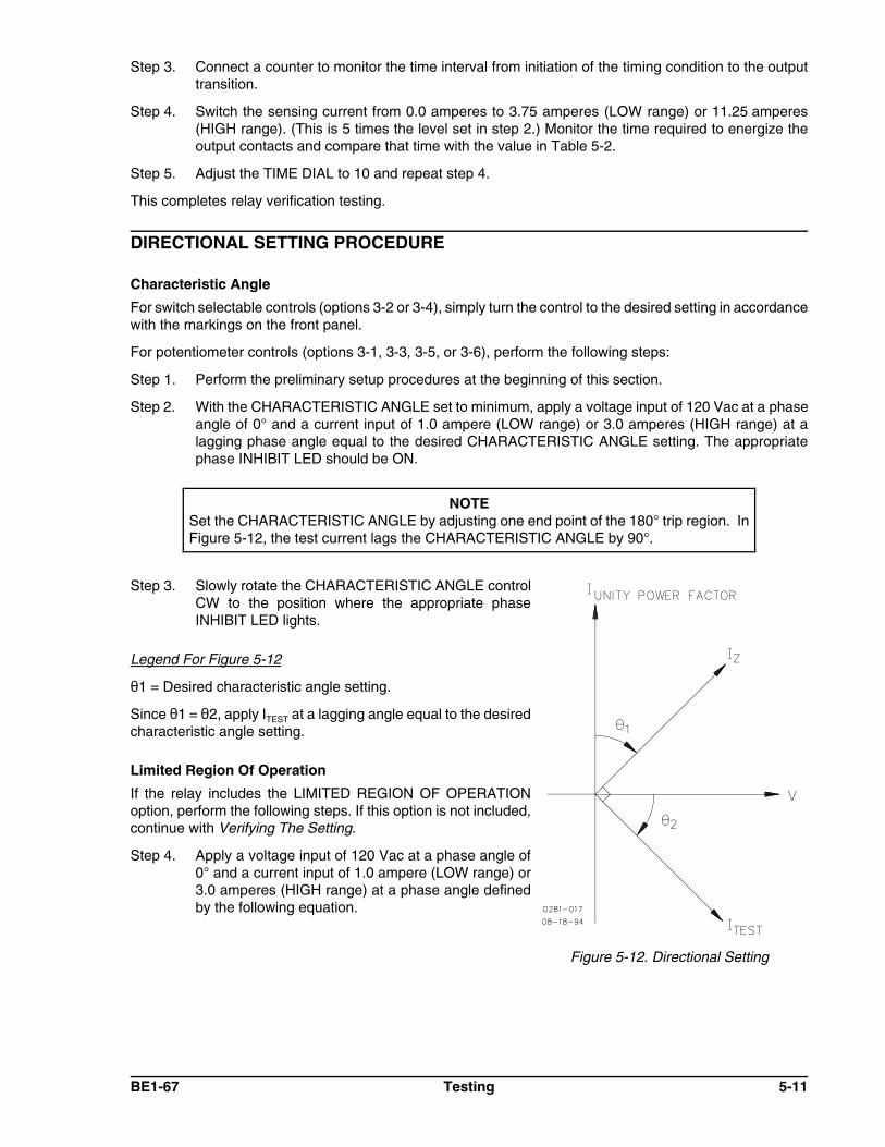
BE1-67 Testing 5-11
NOTESet the CHARACTERISTIC ANGLE by adjusting one end point of the 180° trip region. InFigure 5-12, the test current lags the CHARACTERISTIC ANGLE by 90°.
Figure 5-12. Directional Setting
Step 3. Connect a counter to monitor the time interval from initiation of the timing condition to the outputtransition.
Step 4. Switch the sensing current from 0.0 amperes to 3.75 amperes (LOW range) or 11.25 amperes(HIGH range). (This is 5 times the level set in step 2.) Monitor the time required to energize theoutput contacts and compare that time with the value in Table 5-2.
Step 5. Adjust the TIME DIAL to 10 and repeat step 4.
This completes relay verification testing.
DIRECTIONAL SETTING PROCEDURE
Characteristic Angle
For switch selectable controls (options 3-2 or 3-4), simply turn the control to the desired setting in accordancewith the markings on the front panel.
For potentiometer controls (options 3-1, 3-3, 3-5, or 3-6), perform the following steps:
Step 1. Perform the preliminary setup procedures at the beginning of this section.
Step 2. With the CHARACTERISTIC ANGLE set to minimum, apply a voltage input of 120 Vac at a phaseangle of 0° and a current input of 1.0 ampere (LOW range) or 3.0 amperes (HIGH range) at alagging phase angle equal to the desired CHARACTERISTIC ANGLE setting. The appropriatephase INHIBIT LED should be ON.
Step 3. Slowly rotate the CHARACTERISTIC ANGLE controlCW to the position where the appropriate phaseINHIBIT LED lights.
Legend For Figure 5-12
21 = Desired characteristic angle setting.
Since 21 = 22, apply ITEST at a lagging angle equal to the desiredcharacteristic angle setting.
Limited Region Of Operation
If the relay includes the LIMITED REGION OF OPERATIONoption, perform the following steps. If this option is not included,continue with Verifying The Setting.
Step 4. Apply a voltage input of 120 Vac at a phase angle of0° and a current input of 1.0 ampere (LOW range) or3.0 amperes (HIGH range) at a phase angle definedby the following equation.

5-12 Testing BE1-67
Figure 5-13. Limited Region OfOperation Setting
Refer to Figure 5-13.
Where:PhaseI = phase of the applied current relative to the applied voltage$ = desired LIMITED REGION OF OPERATION setting+ angle = leading current- angle = lagging current
Step 5. Slowly rotate the LIMITED REGION OFOPERATION control CCW until the INHIBIT LEDjust illuminates.
Verifying Relay Settings
A verification of the directional setting should now beperformed.
Step 6. Vary the applied current phase angle through 360°and record the angle values at which theappropriate phase INHIBIT LED turns ON andOFF. Plot the results on a polar coordinate graphfor future reference.
SETTING THE RELAY - AN EXAMPLE
One method of setting the relay is described here. There are other methods that may be used as well. Allmethods involve similar steps and equipment.
Example Defined
Before the relay can be set, the required settings need to be defined. A typical example follows.
Time overcurrent pickup: 5.7 ACurve shape: Very inverseTime delay setting: 0.6 second at 28.5 AInstantaneous overcurrent pickup: 39.9 ALine impedance angle: 60°Limited range of operation: B = 45°
The relay that has been selected for this application is a BE1-67, style number B1E-Z2Y-B1N6F.
Before applying sensing inputs to the relay, a few adjustments are necessary.
Step 1. Since the relay includes the Z2 timing option, the characteristic curve needs to be selected. Thisis accomplished by removing the front panel and adjusting the TIME OVERCURRENTCHARACTERISTIC CURVE SELECTOR switch to position 6. (See Very Inverse, Table 1-4.)
Step 2. Because the time overcurrent pickup is 5.7 amperes, the sensing current input for the relay willneed to be connected for the HIGH range. Adjust the TAP RANGE plate on the front panel todisplay the word HIGH. Verify that the current connections to the relay are on terminals 7 and 8(phase A), 14 and 15 (phase B), and 17 and 18 (phase C). Terminals 9, 13 and 16 should not beconnected.
Step 3. Calculate the ratio of the instantaneous overcurrent pickup setting to the time overcurrent pickupsetting.
In this example, the ratio is 39.9 ÷ 5.7 = 7. (This ratio is used in Step 2, Setting The Pickups.)

BE1-67 Testing 5-13
WARNING!Each current input one-second rating is 50 times TAP or 500 amperes (whichever isless). Take care NOT to exceed the one-second limit. Allow one minute for coolingbetween each current application.
Setting The Pickups
Step 1. Perform the preliminary test setup.
Step 2. Set the following controls to the positions indicated.
! TAP SELECT switch to position A. (TAP is set to the minimum designated tap value of 2.25amperes, HIGH range.)
! TAP CAL control fully CW.
! INST control to full CW.
Step 3. Apply nominal sensing voltage with a phase angle of 0° to the relay.
Step 4. Apply a sensing input current of 7 x 2.25 amperes = 15.75 amperes at a phase angle of -60° (equalto the CHARACTERISTIC ANGLE setting).
Step 5. Slowly adjust the INST control CCW until the instantaneous overcurrent output contact closes.Instantaneous overcurrent pickup is now set for seven times the time overcurrent pickup setting.
Step 6. Reduce the sensing current to zero.
Step 7. Set the following controls to the positions indicated:
! TAP SELECT switch to position E
! TAP CAL control to fully CW
Step 8. Apply a sensing input current of 5.7 amperes.
Step 9. Slowly rotate the TAP CAL control CCW until the TIMING LED lights. Time overcurrent pickup isnow set for 5.7 amperes and the instantaneous overcurrent pickup is set for 39.9 amperes.
Step 10. Reduce the sensing input current to zero.
Step 11. Adjust the TIME DIAL for a setting of 11. (This setting is determined from the characteristic curvefor timing type B6, Very Inverse, Basler Drawing 99-0928 which is included in Basler publication9 1907 00 999.) This setting will give a time delay of 0.6 second at 5 times pickup. This is thedesired coordination point based on the required settings for this example.)
Setting The Direction
To set the direction (characteristic angle) for the relay, the boundaries of the tripping region need to bedetermined. If, for example, the line impedance angle is known to be 60°, the boundary should be the linenormal to the line impedance. This line (through the origin) should extend from +120° to -60° as shown inFigure 5-10.
Step 1 . Adjust the phase angle with the sensed current level at six amperes so that the sensed current(ITEST) lags the sensed nominal voltage input by 60°.
Step 2. Slowly adjust the CHARACTERISTIC ANGLE control until the INHIBIT LED just turns OFF. Thecharacteristic angle of the relay is now set for 60°.
Setting The Limited Range Of Operation
To set the limited range of operation to 40°, follow these steps:

5-14 Testing BE1-67
Step 1. Adjust the current sensing input phase angle to (Current now lags thevoltage by 10°.)
Step 2. Slowly rotate the LIMITED RANGE OF OPERATION control CCW (from maximum setting) until theINHIBIT LED just turns OFF.
Step 3. Vary the applied current phase angle through 360° and record the angle values at which theappropriate phase INHIBIT LED turns ON and OFF. Plot the results on a polar coordinate graphfor future reference. The resultant plot should look like Figure 5-14.
Figure 5-14. " = 60°, Limited Range of Operation = 40°

BE1-67 Maintenance 6-1
CAUTIONSubstitution of printed circuit boards or individual components does not necessarily meanthe relay will operate properly. Always test the relay before placing it in operation.
SECTION 6 MAINTENANCE
GENERAL
The BE1-67, Phase Directional Overcurrent Relay, requires no preventive maintenance other than periodictests. (Refer to Section 5 for test procedures.) If factory repair is desired, contact the Customer ServiceDepartment of the Power Systems Group, Basler Electric, for a return authorization number prior to shipping.
IN-HOUSE REPAIR
In-house replacement of individual components may be difficult and should not be attempted unlessappropriate equipment and qualified personnel are available.
If in-house repair is to be attempted, component values may be obtained from the schematics or the parts listof the Service Manual. Replacement parts may be purchased locally. The quality of replacement parts mustbe at least equal to that of the original components.
Where special components are involved, Basler Electric part numbers may be obtained from the numberstamped on the component or assembly, the schematic or parts list. These parts may be ordered directly fromBasler Electric. When complete boards or assemblies are needed, the following information is required.
1. Relay model and style number
2. Relay serial number
3. Board or assembly
a) Part numberb) Serial numberc) Revision letter
4. The name of the board or assembly
STORAGE
This protective relay contains aluminum electrolytic capacitors which generally have a life expectancy inexcess of 10 years at storage temperatures less than 40 degrees C. Typically, the life expectancy of thecapacitor is cut in half for every 10 degrees C rise in temperature. Storage life can be extended if, at one-yearintervals, power is applied to the relay for a period of thirty minutes.
TEST PLUG
Test plugs (Basler p/n 10095) provide a quick, easy method of testing relays without removing them from thecase. Test plugs are simply substituted for the connection plugs. This provides access to the external studconnections as well as to the internal circuitry.

6-2 Maintenance BE1-67
Test plugs consist of a black and red phenolic molding with twenty electrically separated contact fingersconnected to ten coaxial binding posts. The ten fingers on the black side are connected to the inner bindingposts (black thumb nuts) and tap into the relay internal circuitry. The ten fingers on the red side of the test plugare connected to the outer binding posts (red thumb nuts) and to the relay case terminals.
When testing circuits connected to the bottom set of case terminals, the test plug is inserted with the numbers1 through 10 facing up. When using the test plug in the upper part of the relay, the numbers 11 through 20are face up. Because of the test plug construction, it is impossible to insert it with the wrong orientation.


