INSTRUCTION MANUAL - Icom · IMPORTANT READ THIS INSTRUCTION MANUAL CARE-FULLY before attempting to...
88
INSTRUCTION MANUAL VHF/UHF ALL MODE TRANSCEIVER i910H
-
Upload
truongdieu -
Category
Documents
-
view
226 -
download
3
Transcript of INSTRUCTION MANUAL - Icom · IMPORTANT READ THIS INSTRUCTION MANUAL CARE-FULLY before attempting to...

INSTRUCTION MANUAL
VHF/UHF ALL MODE TRANSCEIVER
i910H

IMPORTANT
READ THIS INSTRUCTION MANUAL CARE-FULLY before attempting to operate the transceiver.
SAVE THIS INSTRUCTION MANUAL. This manual contains important safety and operating in-structions for the IC-910H.
EXPLICIT DEFINITIONS
i
R WARNING HIGH VOLTAGE! NEVER at-tach an antenna or internal antenna connector during transmission. This may result in an electrical shock or burn.
R NEVER apply AC to the [DC13.8V] jack on the transceiver rear panel. This could cause a fire or ruin the transceiver.
R NEVER apply more than 16 V DC, such as a 24 V battery, to the [DC13.8V] jack on the transceiver rear panel. This could cause a fire or ruin the transceiver.
R NEVER let metal, wire or other objects touch any internal part or connectors on the rear panel of the transceiver. This may result in an electric shock.
R NEVER expose the transceiver to rain, snow or any liquids.
AVOID using or placing the transceiver in areas with temperatures below –10°C (+14°F) or above +60°C (+140°F). Be aware that temperatures on a vehicle’s dashboard can exceed 80°C (+176°F), resulting in permanent damage to the transceiver if left there for extended periods.
AVOID placing the transceiver in excessively dusty en-vironments or in direct sunlight.
AVOID placing the transceiver against walls or putting anything on top of the transceiver. This will obstruct heat dissipation.
Place unit in a secure place to avoid inadvertent use by children.
During mobile operation, DO NOT operate the trans-ceiver without running the vehicle’s engine. When the transceiver power is ON and your vehicle’s engine is OFF, the vehicle’s battery will soon become exhaust-ed.
Make sure the transceiver power is OFF before start-ing the vehicle. This will avoid possible damage to the transceiver by ignition voltage spikes.
During maritime mobile operation, keep the transceiv-er and microphone as far away as possible from the magnetic navigation compass to prevent erroneous in-dications.
BE CAREFUL! The heatsink will become hot when op-erating the transceiver continuously for long periods.
BE CAREFUL! If a linear amplifier is connected, set the transceiver’s RF output power to less than the lin-ear amplifier’s maximum input level, otherwise, the lin-ear amplifier will be damaged.
Use Icom microphones only (supplied or optional). Other manufacturer’s microphones have different pin assignments, and connection to the IC-910H may damage the transceiver.
PRECAUTIONS
WORD
R WARNING
CAUTION
NOTE
DEFINITION
Personal injury, fire hazard or electric shock may occur.
If disregarded, inconvenience only. No risk of personal injury, fire or electric shock.
Equipment damage may occur.

SUPPLIED ACCESSORIESThe transceiver comes with the following accesso-ries.
Qty.q DC power cable (OPC-657A) ............................ 1w Hand microphone (HM-36) ............................... 1e Spare fuses (FGB 30 A) .................................... 2r Spare fuse (FGB 4 A) ....................................... 1
1
1
TABLE OF CONTENTS
q w e
r
IMPORTANT ........................................ iEXPLICIT DEFINITIONS ..................... iPRECAUTIONS ................................... i
1 TABLE OF CONTENTS ................ 1
2 PANEL DESCRIPTION ......... 2 – 13 n Front panel ..................................... 2 n Function display ........................... 10 n Rear panel .................................... 12
3 INSTALLATION AND CONNECTIONS .................. 14 – 17
n Unpacking .................................... 14 n Grounding .................................... 14 n Selecting a location ...................... 14 n Antenna connection ..................... 14 n Required connections .................. 15 n Advanced connections ................. 16 n Power supply connections ............ 17
4 BASIC OPERATION ........... 18 – 25 n Initial settings ............................... 18 n When first applying power
(CPU resetting) ............................ 18 n MAIN and SUB bands .................. 19 n Operating band selection ............. 20 n VFO description ........................... 21 n Frequency setting ......................... 22 n SUB band OFF ............................. 24 n SUB tuning dial ............................ 24 n Dial lock function .......................... 25
5 RECEIVE AND TRANSMIT 26 – 39 n Functions for receive .................... 26 n RIT function .................................. 27 n IF shift function ............................. 27 n AGC time constant ....................... 28 n AFC function ................................ 28 n FM center indicator ...................... 28 n Attenuator ..................................... 29 n Simple band scope ....................... 29 n Noise blanker ............................... 30 n Tone squelch operation ................ 30 n Optional DSP functions ................ 31 n Functions for transmit ................... 32 n Transmit via microphone .............. 32
n Indications during transmit ........... 32 n FM mode operation ...................... 33 n VOX operation .............................. 33 n Repeater operation ...................... 34 n SSB mode operation .................... 36 n Speech compressor ..................... 36 n Split frequency operation ............. 37 n Full duplex operation .................... 37 n Connections for CW ..................... 38 n CW mode operation ..................... 38
6 MEMORY OPERATION ...... 40 – 44 n Memory channels ......................... 40 n Operation on a memory channel .. 40 n Programming in VFO mode .......... 41 n Programming in memory mode .... 41 n Blank channels ............................. 42 n Frequency transferring ................. 42 n Memory clearing .......................... 43 n Call channels ................................ 43 n Memo pads .................................. 44
7 SCANS ................................ 45 – 47 n Scan types ................................... 45 n Preparation ................................... 45 n Programmed scan operation ........ 46 n Memory scan operation ............... 46 n Memory select scan ..................... 47 n Tone scan ..................................... 47
8 SATELLITE OPERATION ... 48 – 51 n Satellite communications outline .. 48 n Satellite notes ............................... 48 n Entering into the satellite mode .... 48 n Setting the satellite VFO ............... 49 n Tracking selection ......................... 49 n Preparation ................................... 50 n Satellite operation ........................ 51 n Satellite memory .......................... 51
9 DATA COMMUNICATION ... 52 – 54 n Functions for AFSK ...................... 52 n Connections for AFSK .................. 52 n Operating mode notes .................. 53 n Operating frequency notes ........... 53 n AFSK operation ............................ 53 n Setting the ACC socket ................ 54
10 SET MODE ......................... 55 – 69 n Set mode description ................... 55 n General set mode ......................... 56 n FM set mode ................................ 60 n SSB/CW set mode ....................... 62 n Scan set mode ............................. 64 n Memo pad set mode .................... 64 n Compressor set mode .................. 64 n VOX set mode .............................. 65 n Attenuator set mode ..................... 65 n Transmit set mode ........................ 66 n NR set mode ................................ 67 n SWP set mode ............................. 67 n RIT/SHIFT set mode .................... 68 n Speech set mode ......................... 69
11 OPTION INSTALLATIONS . 70 – 76 n Internal view ................................. 70 n Opening the transceiver’s case .... 71 n UT-102 VOICE SYNTHESIZER
UNIT .............................................. 71 n UT-106 DSP UNIT .......................... 72 n UX-910 1200 MHz BAND UNIT ........ 73 n CR-293 HIGH STABILITY CRYSTAL
UNIT .............................................. 74 n FL-132/FL-133 CW NARROW
FILTER ........................................... 75
12 MAINTENANCE .................. 76 – 77 n Troubleshooting ............................ 76 n Fuse replacement ........................ 77 n CPU resetting ............................... 77
13 CONTROL COMMAND ...... 78 – 79 n Remote jack (CI-V) information .... 78
14 SPECIFICATIONS ...................... 80
15 OPTIONS .................................... 81
16 INSTALLATION NOTES ..... 82 – 83

n Front panel
q POWER SWITCH [POWER] ➥ Push momentarily to turn power ON. ➥ Push for 2 sec. to turn power OFF.
w TRANSMIT SWITCH [TRANSMIT] Push to select transmitting or receiving.
e COMPRESSION SWITCH [COMP] (p. 36) Push to switch the speech compressor function ON
and OFF. •The speech compressor increases average RF output
power, improving signal strength and readability in SSB.
r VOX SWITCH [VOX] (p. 33) Push to switch the VOX function ON and OFF. •TheVOX(Voice-OperatedTransmission)functiontog-
gles between transmit and receive with your voice. This function provides an opportunity to input log entries into your computer, etc., while operating.
t HEADPHONE JACK [PHONES] Accepts headphones. •Outputpower:5mWwith8–16Ω load. •Whenheadphonesareconnected,theinternalspeaker
or connected external speaker does not function. •TheMAINandSUBbandaudiocanbemixedorsepa-
rated when using stereo headphones according to set mode settings. (p. 57)
y MICROPHONE CONNECTOR [MIC] Accepts the supplied or optional microphone. •Seep.81forappropriatemicrophones. •Seep.15formicrophoneconnectorinformation.
u MIC GAIN CONTROL [MIC GAIN] Adjusts microphone input gain.
MIC GAIN
Recommended level for an Icom microphone
IncreasesDecreases
How to set the microphone gain.Set the [MIC] control so that the [MAIN]/[SUB] indicator (ALC indicator) some times lights brighter during normal voice transmission in SSB mode.
i RF POWER CONTROL [RF PWR] Continuously varies the RF output power from min-
imum to maximum. 144 MHz band 5–100 W 430(440) MHz band 5–75 W 1200 MHz band 1–10 W (optional UX-910)
RF PWR
IncreasesDecreases
2
2
PANEL DESCRIPTION
q
o !0 !1 !2!3
w
er
t
y
u i

o MAIN BAND INDICATOR [MAIN] ➥ Lights green while the squelch is opened or a
signal is received on the MAIN band; lights red while transmitting on the MAIN band.
•Whiletransmitting,theindicatoralsoshowsALCcon-dition. Brightness increases more than usual when the ALC function is activated.
➥ Flashes when an off-frequency signal is received and the FM center detector is activated. (p. 28)
!0 RF GAIN CONTROL/SQUELCH CONTROL [RF/SQL] (outer control)
Adjusts the RF gain and squelch threshold level for the MAIN band. The squelch removes noise output from the speaker (closed condition) when no signal is received.
•Thesquelch isparticularlyeffectiveforFM.It isalsoavailable for other modes.
•12to13o’clockpositionisrecommendedforanysettingof the [RF/SQL] control.
•ThesquelchthresholdpositionforSSB/CWmodecanbe set from 12 or 13 o’clock position in SSB/CW set mode. (p. 62)
•The control can be set as ‘Auto’ (RF gain control in SSB and CW; squelch control in FM) or squelch control (RF gain is fixed at maximum) in set mode as follows. (p. 56)
MODE
SSB, CW
FM
AUTO
RF GAIN
SQL
SQLSET MODE SETTING
SQL
SQL
RF GAIN + SQL
RF GAIN + SQL
SQL
• When setting as RF gain/squelch control
Recommended level
RF gain adjustablerange (SSB, CW modes)
Maximum RF gain
S-meter squelch
Noise squelch (FM mode)
Squelch is open.
• When functioning as RF gain control (Squelch is fixed open; SSB, CW only)
Minimum RF gain
Adjustablerange
Maximum RF gain
• When functioning as squelch control (RF gain is fixed at maximum.)
Squelch is open.
S-meter squelch
S-meter squelchthreshold
Noise squelch threshold
Shallow Deep
Noise squelch
!1 AF CONTROL [AF] (inner control) Varies the audio output level from the speaker for
the MAIN band.
AF RF/SQL
No audio output Max. audio output
Decreases Increases
!2 SUB BAND INDICATOR [SUB] Lights green while the squelch is opened or a sig-
nal is received on the SUB band; lights red while transmitting in satellite operation.
!3 RF GAIN CONTROL/SQUELCH CONTROL [RF/SQL] (outer control)
Adjusts the RF gain and squelch threshold level for the SUB band. The squelch removes noise output from the speaker (closed condition) when no signal is received.
3
2PANEL DESCRIPTION

4
2 PANEL DESCRIPTION
n Front panel (continued)
!4 AF CONTROL [AF] (inner control) Varies the audio output level from the speaker for
the SUB band.
!5 SET•MENU SWITCH [SET•MENU] (p. 55)➥ Push this switch then one of [FM],
[SSB/CW], [RIT], [SCAN], [NR], [TRANS-MIT], [COMP], [VOX], [ATT], [SWP], [MPW] or [SPCH] to enter the indepen-dent item set mode.
For 1 sec.
➥ Push for 1 sec. to enter the set mode for commonly used item settings.
!6 ATTENUATOR•PRE-AMP SWITCH [ATT•P.AMP]➥ Push to switch the attenuator function
ON and OFF. (p. 29) Use this function to protect from signal distortion from exces-sively strong signals.
•Theattenuation level is independentlyad-justable for 144 MHz or 430(440) MHz band in the ATT set mode. The optional 1200 MHz band attenuation level is fixed and is approx. 20 dB. (p. 65)
For 1 sec.
➥ Push for 1 sec. to switch the connected pre-amplifier ON and OFF, when an op-tional pre-amplifier unit, AG-25, AG-35 and/or AG-1200, is connected. (p. 16)
DO NOT connect any equipment, such as an SWR or power meter between the transceiver and pream-plifier. In such case, the preamplifier may not acti-vate properly.
!7 AUTO FREQUENCY CONTROL/NOISE BLANKER•NOISE REDUCTION SWITCH [AFC/NB•NR]
➥ During FM/FM narrow mode operation, push to switch the AFC (Automatic Fre-quency Control) function ON and OFF. (p. 28)
•Automaticallytunestheoperatingfrequency,when an off-frequency signal is received, in 100 kHz steps. This function also follows the signal even if the frequency is shifted.
➥ During SSB or CW mode operation, push to switch the noise blanker function ON and OFF. (p. 30)
•Reducespulse-typenoise,suchasignitionnoise from a vehicle.
For 1 sec.
➥ Push for 1 sec. to switch the noise reduc-tion function ON and OFF when an op-tional DSP unit, UT-106, is installed. (p. 31)
•Reducesunwantednoiseandpullsoutthedesired signal only for clear readability.
!4 !5 !6 !7 !8 !9 @0 @1 @2 @3
5
2PANEL DESCRIPTION
!8 AUTO GAIN CONTROL•AUTO NOTCH FILTER SWITCH [AGC•ANF]
➥ Push to switch the time constant of the automatic gain control to SLOW and FAST for the MAIN band.* (p. 28)
•SLOWselection(“FAGC”disappears)duringSSB (USB or LSB) operation, FAST selec-tion(“FAGC”appears)duringCW,dataop-eration and while tuning with fast tuning dial rotation are recommended.
* The AGC time constant can be selected on the MAIN band only. FAST selection is fixed on the SUB band.
For 1 sec.
➥ Push for 1 sec. to switch the automatic notch filter function ON and OFF when the optional DSP unit, UT-106, is in-stalled. (p. 31)
•Reduces interference signals such as beat, RTTY or CW signals and the notch frequency automatically follows the interfering signal.
!9 kHz/MHz•TUNING STEP SELECTION SWITCH [kHz/MHz] (p. 22)
➥ Push to select tuning step for the tuning dial or scanning from 1 kHz, 1 MHz step and regular tuning step* in sequence
•“Z”appearsabovethe1kHzor1MHzdigitwhen 1 kHz or 1 MHz tuning step is select-ed, respectively.
* The regular tuning step is selected for each operating mode as follows.
For 1 sec.
➥ Push for 1 sec. to enter the regular tun-ing step selection mode.
•Thetuningstepcanbeselectedforeachop-erating mode independently.
•SSB/CWmode:1,10,50and100Hzstep;FMmode:0.1,5,6.25,10,12.5,20,25and100 kHz step can be selected by rotating the tuning dial.
@0 SPEECH•LOCK SWITCH [SPCH•LOCK] ➥ Announces the receiving signal strength
and/or selected readout frequency when the optional UT-102 is installed. (pgs. 69, 71)
For 1 sec.
➥ Push for 1 sec. to switch the tuning dial lock function ON and OFF to prevent ac-cidental setting changes. (p. 25)
@1 TUNING DIAL Changes the displayed frequency, selects set mode
items, etc.
@2 BRAKE ADJUSTMENT SCREW Adjust the tension of the tuning dial. •Rotateclockwisetoincreasethetension;counterclock-
wise to decrease the tension.
Brake adjustment screw
@3 MEMORY CHANNEL UP/DOWN SWITCHES [Y UP]/[DOWN Z] (p. 40)
or
➥ Push [Y UP] to change the memory channel up; push [DOWN Z] to change the memory channel down.
•Memorychannelchangescontinuouslywhileholding either switch.
•Memorychannelscanbeselectedboth inVFO and memory modes.
For 1 sec.
or

6
2 PANEL DESCRIPTION
@4 RIT CONTROL [RIT] (p. 27) Shifts the receive frequency without changing the
transmit frequency for the MAIN band only while the RIT function is activated.
•SSB/CWmode :±1.0kHz*in10Hzstep •FMmode :±5.0kHz*in50Hzstep *For1200MHzband;±2.0kHzand±10.0kHz,respec-
tively when the optional UX-910 is installed. •ByusingtheSubdialfunction,theRITcontrolcanbe
used as the MAIN/SUB tuning dial or the SUB band IF shift control. See page 24 for details.
@5 IF SHIFT CONTROL [SHIFT] Shifts the center frequency of the receiver’s IF pass-
band within 1.2 kHz range. •ByusingtheSubdialfunction,theIFshiftcontrolcan
be used as the MAIN/SUB tuning dial or the SUB band IF shift control. See page 24 for details.
What is the Sub dial function?The [RIT] and [SHIFT] controls are used for RIT and IF shift controls for the MAIN band by default. However, the Sub dial function assigns these controls as the MAIN/SUB tuning dial or the SUB band IF shift control. (p. 24, 68)
RIT SHIFT RIT SHIFT RIT SHIFT
Center positionMax. counter-clockwise position
Max. clockwise position
@6 SATELLITE SWITCH [SATELLITE]➥ Push to enter satellite mode (RX on
MAIN, TX on SUB band). Push again to return to the condition before entering into the satellite mode.
For 1 sec.
➥ Push to enter satellite mode using the current operating frequencies when pushing for 1 sec.
For 1 sec.
•Tochangethenormalandreversesatelliteoperations, push [F-INP/ENT] for 1 sec.
@7 RIT SWITCH [RIT] (p. 27)➥ Push to switch the RIT control activity
ON and OFF. •“RIT”indicatorappearswhentheRITfunc-
tion is in use.
For 1 sec.
➥ Push for 1 sec. to switch the Sub dial function ON and OFF.
•“RIT” indicator flashes and the [RIT] and[SHIFT] controllers acts as the controllers specified in the RIT/SHIFT set mode. (p. 68)
@8 KEYPAD Numeral and other function keys for tuning and ac-
tivating functions. See the table at right.
n Front panel (continued)
@4
@5
@6
@8
@7

7
2PANEL DESCRIPTION
•Entersnumeral“1”whenenteringanoperatingfrequency. (p. 23)
•Switches between VFO and memory mode.(p. 40)
Entersnumeral“2”whenenteringanoperatingfrequency. (p. 23)
•Entersnumeral“3”whenenteringanoperatingfrequency. (p. 23)
•SwitchesbetweenVFOAandBduringVFOmode operation. (p. 21)
Entersnumeral“4”whenenteringanoperatingfrequency. (p. 23)
Entersnumeral“5”whenenteringanoperatingfrequency. (p. 23)
Entersnumeral“6”whenenteringanoperatingfrequency. (p. 23)
Entersnumeral“7”whenenteringanoperatingfrequency. (p. 23)
•Entersnumeral“8”whenenteringanoperatingfrequency. (p. 23)
•Storesthedisplayedoperatingconditions intoMEMO PAD channel (p. 44)
•Entersnumeral“9”whenenteringanoperatingfrequency. (p. 23)
•Re-callsthecontentsintheMEMOPADchan-nel. (p. 44)
•Entersdecimalpoint“.” forenteringbelowthe“MHz“ digits when entering an operating fre-quency.
•Startsandcancelsscanningfunction.(p.46)•TurnsOFFtheSUBbandfrequencyindication
during satellite operation. In this case, only the MAIN band frequency can be tuned by rotating the tuning dial. (p. 49)
•Entersnumeral“0”whenenteringanoperatingfrequency. (p. 23)
•SwitchessweepfunctionforthebandscopeONand OFF. (p. 29)
•TurnsOFFtheMAINbandfrequencyindicationduring satellite operation. In this case, only the SUB band frequency can be tuned by rotating the tuning dial. (p. 49)
Enables operating frequency entering from the keypad. See page 23 for details.
Equalizes the condition of the VFO A and B. (p. 21)
Shows 10 Hz and 1 Hz digits of operating fre-quency on both the MAIN and SUB bands while pushing and holding. (p. 22)
Stores the set conditions into a memory channel. (p. 41)
Clears stored contents of memory channel to be a blank channel. (p. 43)
Transfers the contents of a memory channel into either the VFO A or B. (p. 42)
Opens squelch for monitoring the operating or transmit frequency, and the frequency indication automatically changes to transmit frequency in the case of duplex or split operation. (p. 34)
Starts and cancels tone scan when the repeater tone or tone squelch is activated in FM (narrow) operation. (p. 47)
Used to change memory channel during memo-ry mode operation by rotating the tuning dial while pushing and holding. (p. 40)
Switch Switch action when pushed Switch action when pushed for 1 sec.

8
2 PANEL DESCRIPTION
@9 SPLIT•DUPLEX SWITCH [SPLIT•DUP]➥ Push to turn the split function, with the
VFO A and B, ON and OFF. (p. 37) •Thesplitoperation isnotavailable for the
SUB band.
For 1 sec.
➥ Push for 1 sec. to select the duplex (re-peater) direction or to turn the function OFF. (p. 34)
•TheduplexoperationisnotavailablefortheSUB band.
#0 SSB/CW•CW-NARROW SWITCH [SSB/CW•CW-N]
➥ Push to switch the operating mode be-tween SSB and CW. (p. 23)
For 1 sec.
➥ Push for 1 sec. to switch the operating mode between USB and LSB or be-tween CW and CW narrow during SSB or CW mode, respectively.
#1 FM•FM-NARROW SWITCH [FM•FM-N] (p. 23)➥ Push to switch the operating mode be-
tween FM and FM repeater mode. •The duplex operation can be made in
MAIN band only, it cannot be operated in SUB band.
For 1 sec.
➥ Push for 1 sec. to switch the operating mode between FM and FM-N (FM nar-row).
•The FM-N mode cannot be selected in1200 MHz band operation.
#2 TONE SWITCH [TONE] (p. 34)➥ Push to turn the tone encoder function
ON and OFF in FM mode. (except Eu-rope, Sweden and Italy versions)
•“T”indicatorappearsinthedisplaywhenthetone encoder is activated.
➥ Push to transmit a 1750 Hz repeater tone in FM mode for European, Sweden and Italy versions.
Available repeater tones (Unit:Hz)
#3 MAIN/SUB CHANGE•BAND SWITCH [M/S•BAND]
➥ Push to replace the MAIN band’s fre-quency and mode with the SUB band’s. (p. 19)
For 1 sec.
➥ Push for 1 sec. to change the operating band during single band operation or when the optional band unit, UX-910, is installed. (p. 20)
#5 #4 #3 #2 #1 #0 @9
67.069.371.974.477.079.782.5
085.4088.5091.5094.8097.4100.0103.5
107.2110.9114.8118.8123.0127.3131.8
136.5141.3146.2151.4156.7159.8162.2
165.5167.9171.3173.8177.3179.9183.5
186.2189.9192.8196.6199.5203.5206.5
210.7218.1225.7229.1233.6241.8250.3
254.1
n Front panel (continued)
9
2PANEL DESCRIPTION
#4 SUB•SUB OFF SWITCH [SUB•SUB OFF]➥ Push to enable the SUB band control
from the tuning dial, keypad, etc. (p. 19) •“SUB”indicatorappears.
For 1 sec.
➥ Push for 1 sec. to turn the SUB band readout indication ON and OFF. (p. 24)
#5 CALL•TONE SQUELCH SWITCH [CALL•T-SQL]➥ Push to select the call channel of the op-
erating band. The call channel can be selected from both the VFO and memory mode operation. (p. 43)
For 1 sec.
➥ Push for 1 sec. to turn the tone squelch function ON and OFF during FM mode operation. (p. 30)
•“T-SQL” indicator appears when the tonesquelch is activated.
10
2 PANEL DESCRIPTION
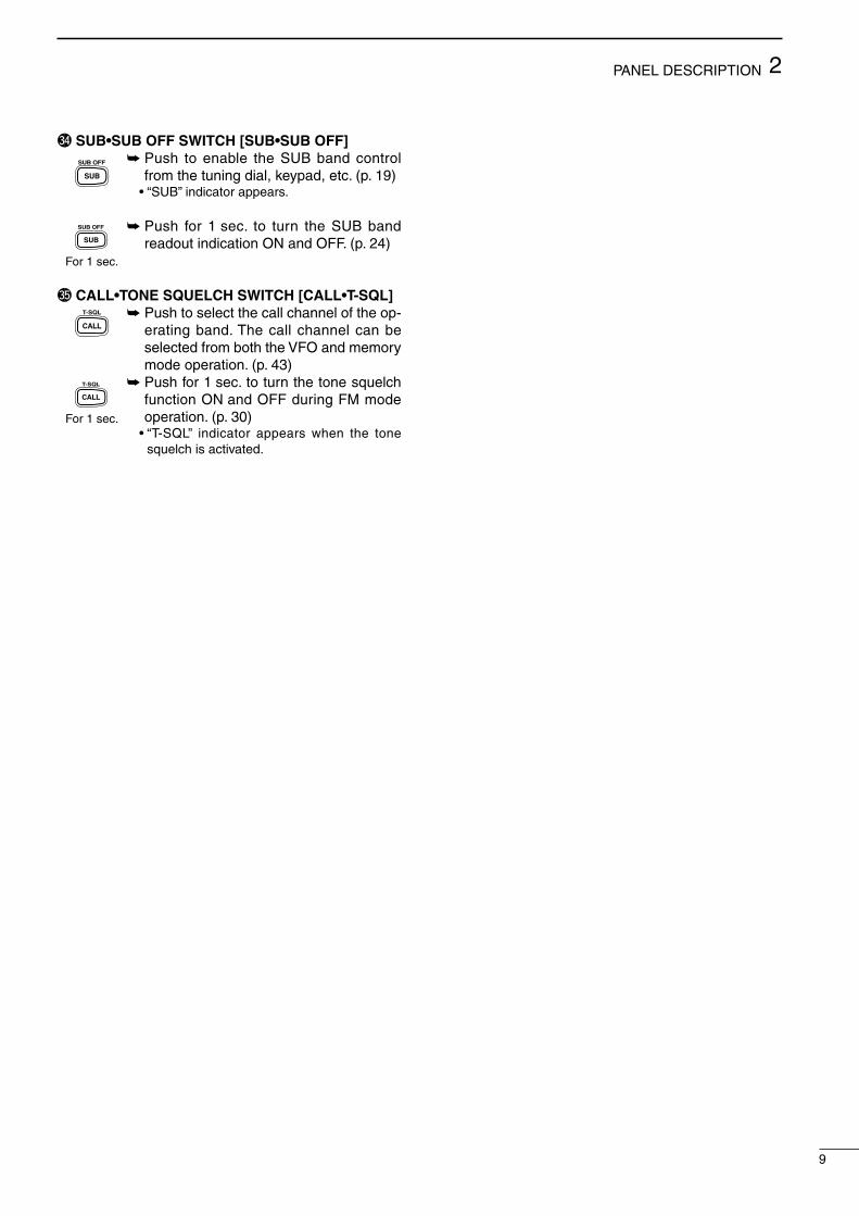
q FREQUENCY READOUTS (p. 22) Shows the operating frequency. •Settingitemnameisindicatedduringsetmode.(p.55)
w MODE INDICATOR (p. 23) Shows the selected operation mode.
e TUNING STEP INDICATOR (p. 22) Appears when the 1 kHz or 1 MHz tuning step is
selected.
r DUPLEX INDICATOR (p. 34) Either“DUP–”or“DUP+”appearsduringduplex(re-
peater) operation.
t SPLIT INDICATOR (p. 37) Appears during split operation.
y RIT INDICATOR (p. 27) ➥ Appears while the RIT function is activated. ➥ Flashes while the SUB dial function is activated.
u VFO INDICATOR (p. 21) Either VFO A or VFO B appears during VFO opera-
tion.
i MEMORY MODE INDICATORS/MEMORY CHANNEL NUMBER READOUTS (p. 40)
The memory mode indicator appears during mem-ory mode operation and the memory channel num-ber readout shows the selected memory channel number during both the memory and VFO mode operation.
Memory channel number readoutIn addition to the memory channel number indication, the memory channel number readout indicates 10 Hz and 1 Hz digits of operating frequency while rotating the tuning dial in SSB or CW mode with 10 or 1 Hz tuning step. After 2 sec. from tuning dial operation, the readout indicates the memo-ry channel number.
o AUTO NOTCH FILTER INDICATOR (p. 31) Appears when the optional DSP unit, UT-106, is in-
stalled, and the ANF (Automatic Notch Filter) func-tion is activated.
!0 BLANK INDICATOR (p. 42) Appears when the selected memory channel has
not been programmed or has been cleared.
VFO AVFO BMEMO
RITCW NLSBUSBNFMSUBNOR
SATL
REV
LOCK
T-SQLS 1 3 5 7 9 20 40 60dB
ATT P.AMP AFCNB FAGC NR ANF BLANK
SWPSCAN
O V E R
MEMO
FMNUSBLSBCW N RITSPLIT VFO AVFO B
SET
BLANKT-SQL ATT P.AMP AFC NB FAGC NR ANF9600COMPSWP60dB
VOXSCANO V E R
S 1 3 5 7 9 20 40
DUP
q
q
w
w
e
e
r t y
y
u
u
i
i
o
o
!0
!0
!1!2
!3!4!5
!5
!6
!6
!7
!7
!8
!8
!9
!9
@0
@0
@1
@1
@2
@2
@3
@3
@5
@6
@7
@8
@4
@4
n Function display
11
2PANEL DESCRIPTION
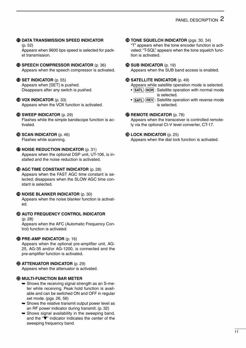
!1 DATA TRANSMISSION SPEED INDICATOR (p. 52)
Appears when 9600 bps speed is selected for pack-et transmission.
!2 SPEECH COMPRESSOR INDICATOR (p. 36) Appears when the speech compressor is activated.
!3 SET INDICATOR (p. 55) Appears when [SET] is pushed. Disappears after any switch is pushed.
!4 VOX INDICATOR (p. 33) Appears when the VOX function is activated.
!5 SWEEP INDICATOR (p. 29) Flashes while the simple bandscope function is ac-
tivated.
!6 SCAN INDICATOR (p. 46) Flashes while scanning.
!7 NOISE REDUCTION INDICATOR (p. 31) Appears when the optional DSP unit, UT-106, is in-
stalled and the noise reduction is activated.
!8 AGC TIME CONSTANT INDICATOR (p. 28) Appears when the FAST AGC time constant is se-
lected; disappears when the SLOW AGC time con-stant is selected.
!9 NOISE BLANKER INDICATOR (p. 30) Appears when the noise blanker function is activat-
ed.
@0 AUTO FREQUENCY CONTROL INDICATOR (p. 28)
Appears when the AFC (Automatic Frequency Con-trol) function is activated.
@1 PRE-AMP INDICATOR (p. 16) Appears when the optional pre-amplifier unit, AG-
25, AG-35 and/or AG-1200, is connected and the pre-amplifier function is activated.
@2 ATTENUATOR INDICATOR (p. 29) Appears when the attenuator is activated.
@3 MULTI-FUNCTION BAR METER ➥ Shows the receiving signal strength as an S-me-
ter while receiving. Peak hold function is avail-able and can be switched ON and OFF in regular set mode. (pgs. 26, 56)
➥ Shows the relative transmit output power level as an RF power indicator during transmit. (p. 32)
➥ Shows signal availability in the sweeping band, andthe“Z”indicatorindicatesthecenterofthesweeping frequency band.
@4 TONE SQUELCH INDICATOR (pgs. 30, 34) “T”appearswhenthetoneencoderfunctionisacti-
vated;“T-SQL”appearswhenthetonesquelchfunc-tion is activated.
@5 SUB INDICATOR (p. 19) Appears when the SUB band access is enabled.
@6 SATELLITE INDICATOR (p. 49) Appears while satellite operation mode is selected. • SATL - NOR :Satelliteoperationwithnormalmode
is selected. • SATL - REV :Satelliteoperationwithreversemode
is selected.
@7 REMOTE INDICATOR (p. 78) Appears when the transceiver is controlled remote-
ly via the optional CI-V level converter, CT-17.
@8 LOCK INDICATOR (p. 25) Appears when the dial lock function is activated.

12
2 PANEL DESCRIPTION
n Rear panel
q 430(440) MHz ANTENNA CONNECTOR (p. 15) Accepts a 50 Ω antenna with a type-N connector.
w DC POWER SOCKET [DC 13.8V] (p. 17) Accepts 13.8 V DC through the supplied DC power
cable (OPC-657A).
Rear panelview
+_
e 144 MHz ANTENNA CONNECTOR (p. 15) Accept a 50 Ω antenna with a PL-259 connector.
r SUB BAND EXTERNAL SPEAKER JACK [SP (SUB)]
t MAIN BAND EXTERNAL SPEAKER JACK [SP (MAIN)] (p. 16)
Accepts a 4–8 Ω speaker. By connecting an external speaker for each or both
jacks, the audio for both the MAIN and SUB bands is output as follows.
y 1200 MHz ANTENNA CONNECTOR (p. 15) Available when the optional 1200 MHz band unit
is installed. Accepts a 50 Ω antenna with a type-N connector.
u KEY JACK [KEY] (p. 15) Accepts a paddle, a straight key or external elec-
tronic keyer with 1⁄8 inch standard plug.
(+)
(_)
(dot)(com)(dash)
i SUB BAND DATA SOCKET [DATA (SUB)]o MAIN BAND DATA SOCKET [DATA (MAIN)]
(p. 13) 6-pin mini plug DIN jack to connect a TNC, etc. for
high speed data communications. Independent data sockets enable simultaneous re-
ception in both MAIN and SUB bands for data com-munication.
(MAINband:TX/RX,SUBband:RXonly)
!0 ACCESSORY SOCKET [ACC(1)] Enables connection of external equipment such as
a TNC for data communications, etc. •Seetherighttableforsocketinformation.
!1 CI-V REMOTE CONTROL JACK [REMOTE] (p. 78)
Designed for use with a personal computer via the optional CT-17 for remote control of transceiver functions.
!2 GROUND TERMINAL [GND] (p 14) Connect this terminal to a ground to prevent electri-
cal shocks and other problems.
o!2
w e
rtyui
q
!0!1
MAIN AF SUB AFNo Int. SP Int. SPSP (MAIN) Ext. SP Ext. SPSP (SUB) Int. SP Ext. SPBoth Ext. SP (MAIN) Ext. SP (SUB)

13
2PANEL DESCRIPTION
D ACC SOCKETS
D DATA SOCKETSo MAIN BAND DATA SOCKET DATA Socket Pin No. Pin Name Description
1
2
3
4
5
6
DATA IN
GND
PTTP
DATA OUT
AF OUT
SQL
Input terminal for data (common for both 1200 and 9600 bps)
Ground line for the DATA IN, DATA OUT and AF OUT.
Transmits when this terminal is grounded.
Received data output terminal for 9600 bps operation.
Received data output terminal for 1200 bps operation.
Output terminal for squelch condition (Open/Close). Outputs grounded level signal when squelch is opened, +8 V level signal when squelch is closed.
q w
e
yt
r
ACC(1) Socket Pin No. Pin Name Description Specification
1
2
3
4
5
6
7
8
NC
GND
SEND
MOD
AF
SQLS
13.8 V
ALC
No connection.
Connect to ground.
Input terminal to transmit the trans-ceiver in relation to the external equip-ment.(Grounded:transmits)
Input terminal for the modulation cir-cuit.
Output terminal for AF signals from the AF detector circuit. Output level is fixed, regardless of [AF] control.
Output terminal for squelch condition (Open/Close). Outputs grounded level signal when squelch is opened.
Output terminal for 13.8 V DC, in rela-tion to the [POWER].
Input terminal for ALC control.
Transmitvoltage :–0.5to+0.8VOutputcurrent :Lessthan20mAInputcurrent(Tx) :Lessthan200mA
Outputimpedance :10kΩInputlevel :100mVrms
Outputimpedance :4.7kΩOutputlevel :100–300mVrms
Squelchopen :Lessthan0.3V/5mASquelchclose :Morethan6.0V/100µA
Outputcurrent :Lessthan1A
Inputimpedance :Morethan10kΩControlvoltage :–4to0V
1
2
3
4 5
6 7
8
DATA Socket Pin No. Pin Name Description
1
2
3
4
5
6
NC
GND
NC
DATA OUT
AF OUT
SQL
No connection.
Ground line for the DATA OUT and AF OUT.
No connection.
Received data output terminal for 9600 bps operation.
Received data output terminal for 1200 bps operation.
Output terminal for squelch condition (Open/Close). Outputs grounded level signal when squelch is opened, +8 V level signal when squelch is closed.
q w
e
yt
r
i SUB BAND DATA SOCKET
3
14
INSTALLATION AND CONNECTIONS
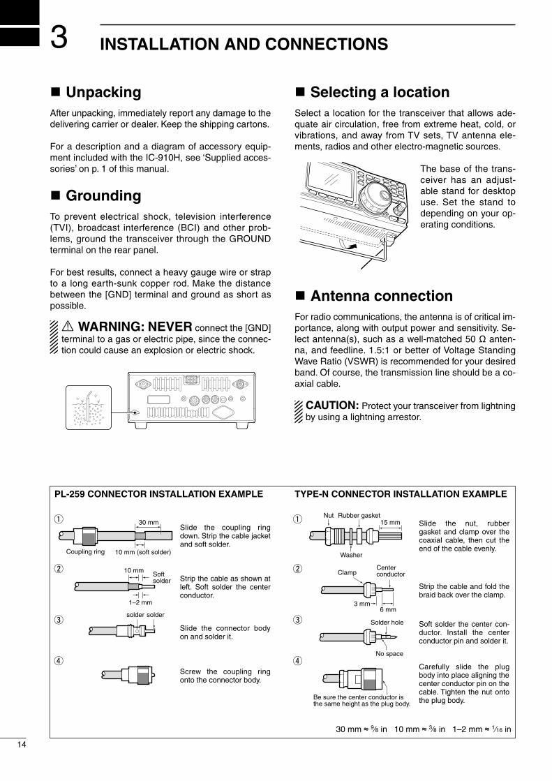
n UnpackingAfter unpacking, immediately report any damage to the delivering carrier or dealer. Keep the shipping cartons.
For a description and a diagram of accessory equip-ment included with the IC-910H, see ‘Supplied acces-sories’ on p. 1 of this manual.
n GroundingTo prevent electrical shock, television interference (TVI), broadcast interference (BCI) and other prob-lems, ground the transceiver through the GROUND terminal on the rear panel.
For best results, connect a heavy gauge wire or strap to a long earth-sunk copper rod. Make the distance between the [GND] terminal and ground as short as possible.
R WARNING: NEVER connect the [GND] terminal to a gas or electric pipe, since the connec-tion could cause an explosion or electric shock.
n Selecting a locationSelect a location for the transceiver that allows ade-quate air circulation, free from extreme heat, cold, or vibrations, and away from TV sets, TV antenna ele-ments, radios and other electro-magnetic sources.
The base of the trans-ceiver has an adjust-able stand for desktop use. Set the stand to depending on your op-erating conditions.
n Antenna connectionFor radio communications, the antenna is of critical im-portance, along with output power and sensitivity. Se-lect antenna(s), such as a well-matched 50 Ω anten-na,andfeedline.1.5:1orbetterofVoltageStandingWave Ratio (VSWR) is recommended for your desired band. Of course, the transmission line should be a co-axial cable.
CAUTION: Protect your transceiver from lightning by using a lightning arrestor.
PL-259 CONNECTOR INSTALLATION EXAMPLE TYPE-N CONNECTOR INSTALLATION EXAMPLE
30 mm ≈ 9⁄8 in 10 mm ≈ 3⁄8 in 1–2 mm ≈ 1⁄16 in
Slide the coupling ring down. Strip the cable jacket and soft solder.
Slide the connector body on and solder it.
Screw the coupling ring onto the connector body.
Strip the cable as shown at left. Soft solder the center conductor.
q
w
e
r
Slide the nut, rubber gasket and clamp over the coaxial cable, then cut the end of the cable evenly.
Strip the cable and fold the braid back over the clamp.
Soft solder the center con-ductor. Install the center conductor pin and solder it.
Carefully slide the plug body into place aligning the center conductor pin on the cable. Tighten the nut onto the plug body.
q
w
e
r
15 mm
3 mm6 mm
30 mm
10 mm (soft solder)
10 mm
1–2 mm
solder solder
Softsolder
Coupling ring
No space
Solder hole
Be sure the center conductor is the same height as the plug body.
ClampCenterconductor
Washer
Nut Rubber gasket

DC POWER SUPPLY (p. 17)[430(440)MHz ANT] (p. 14)
[1200MHz ANT] (p. 14)
[144MHz ANT] (p. 14)
[KEY] jack (p. 38)GROUND (p. 14)
Required for optional UX-910 operation.
+_
13.8 V DC More than 25 A
(dot)(com)(dash)
+
_
15
3INSTALLATION AND CONNECTIONS
SM-20 DESKTOP MICROPHONE (optional)
MICROPHONE CONNECTOR (Front panel view)
Input impedance: 8–16 ΩAudio output power: 5 mW with 8 Ω load Output power may differ according to the headphone
HM-36 HAND MICROPHONE
HEADPHONES
q MIC (Microphone input)w +8V (Max. 8 V DC 10 mA)e MIC U/D (Frequency up/down)r SQL S (Squelch switch)t PTTy GND (PTT ground)u GND (Microphone ground)i AF OUT (varies with [AF])
CAUTION: DO NOT short pin 2 to ground as this can damage the internal 8 V regulator. DC voltage is applied to pin 1 for microphone operation. Take care when using a non-Icom microphone.
q
w
e
r
t
y
u
i
n Required connections• Front panel
• Rear panel

16
3 INSTALLATION AND CONNECTIONS
MB-23 CARRYING HANDLE
PREAMP (p. 59)(144 MHz/430(440) MHz/1200 MHz)
EXTERNAL SPEAKER(MAIN/SUB) (p. 12)
CT-17
144 MHz : AG-25430(440) MHz : AG-351200 MHz : AG-1200
External all-weather, mast mounting preamplifiers are available.
MAIN
MAIN
144 MHz430(440) MHz 1200 MHz (optional)
SUB
SUB
sp-7icom
Use 4–8 Ω speakers.
[REMOTE] (p. 78)
Used for computer control and transceive operation.
Used for external equipment control.
ACC SOCKETS (pgs. 13, 52)
DATA SOCKETS (MAIN/SUB) (pgs. 13, 52)
CAUTION: NEVER connect equipment (i.e. power, SWR meter) between transceiver and preamplifier.
n Advanced connections• Front panel
• Rear panel

AC outlet
AC cable
13.8 V DC 25 A
A DC power supply
Black_
Red+
IC-910HSupplied DC power cable
17
3INSTALLATION AND CONNECTIONS
24VCiga
IC-910H
12 Vbattery
SuppliedDC power cable
+ red_ black
Crimp
Solder
Grommet
CONNECTING A VEHICLE BATTERY
CONNECTING A DC POWER SUPPLY
n Power supply connectionsUse an optional DC power supply with a 25 A capac-ity and above when operating the transceiver with AC power. Refer to the diagrams below.
CAUTION: Before connecting the DC power cable, checkthefollowingimportantitems.Makesure:•The[POWER]switchisOFF.•Output voltageof thepowersource is12–15V
when you use a non-Icom power supply.•DCpowercablepolarityiscorrect. Red :positive+ terminal Black :negative_ terminal
NEVER connect to a 24 V battery.
NEVER use the cig-arette lighter socket as a power source.
NOTE: Use terminals for the cable connections.

n Initial settingsAfter resetting the transceiver, set controls and switch-es as shown in the figure below.
Turn power ON, then check the display. If any of the followingindicatorsappear,turnthemOFFasfollows:
•Quicktuningstepindicator“Z”:Push[kHz/MHz].•RITindicator“RIT” :Push[RIT].•Splitindicator“SPLIT” :Push[SPLIT].
CCW :Max.counterclockwise
4
18
BASIC OPERATION
n When first applying power (CPU resetting)Before first applying power, make sure all connections required for your system are complete by referring to Chapter 3. Then, reset the transceiver using the follow-ing procedure.
q Make sure the transceiver power is OFF.w While pushing [MW 4] and [M-CL 5], push [POWER]
to turn power ON. •TheinternalCPUisreset. •ThetransceiverdisplaysitsinitialVFOfrequencieswhen
resetting is complete.
[POWER] [MW 4] [M-CL 5]
Resetting CLEARS all programmed contents in memory channels and returns programmed values in set mode to default values.
FM VFO A
VFO AFM
S 1 3 5 7 9 20 40 60dB
60dBS 1 3 5 7 9 20 40
[TRANSMIT]: OFF
[COMP]: OFF
[VOX]: OFF
[AF] (SUB band):CCW
[RF/SQL]: (SUB band)12 o’clock
[MIC]: CCW[SET]: OFF
[ATT(P.AMP)]: OFF[RF PWR]: CCW
[AFC/NB]: OFF
[AGC]: OFF
[RIT]: 12 o’clock
[SHIFT]: 12 o’clock
[RIT]: OFF
[POWER]: OFF
[AF] (MAIN band): CCW
[RF/SQL] (MAIN band):12 o’clock [SATELLITE]: OFF
19
4BASIC OPERATION
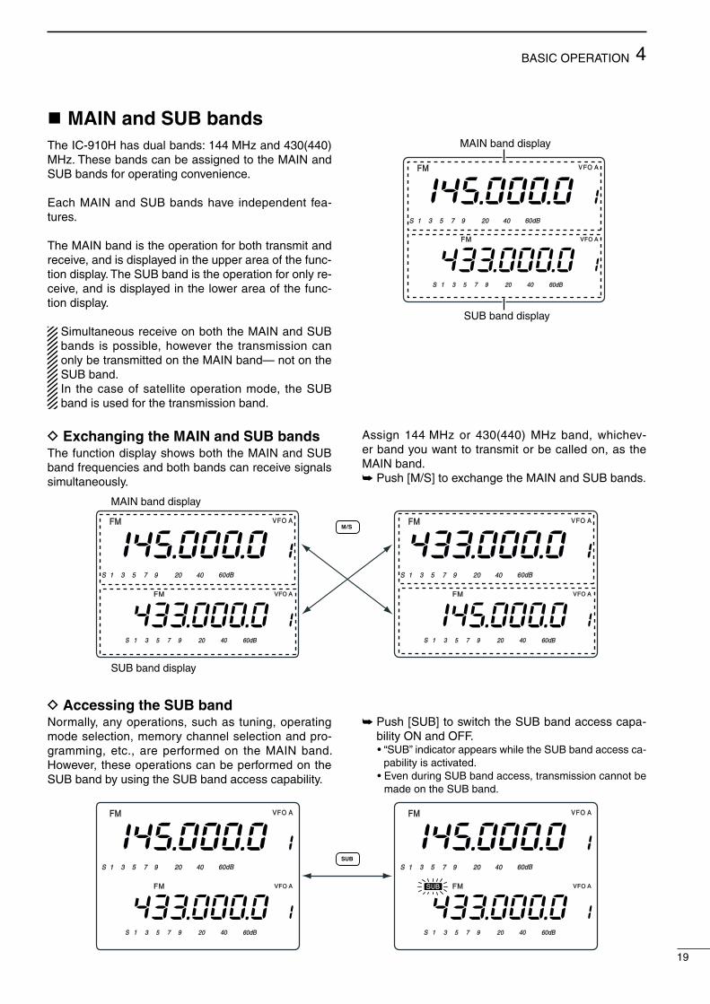
n MAIN and SUB bandsTheIC-910Hhasdualbands:144MHzand430(440)MHz. These bands can be assigned to the MAIN and SUB bands for operating convenience.
Each MAIN and SUB bands have independent fea-tures.
The MAIN band is the operation for both transmit and receive, and is displayed in the upper area of the func-tion display. The SUB band is the operation for only re-ceive, and is displayed in the lower area of the func-tion display.
Simultaneous receive on both the MAIN and SUB bands is possible, however the transmission can only be transmitted on the MAIN band— not on the SUB band. In the case of satellite operation mode, the SUB band is used for the transmission band.
D Exchanging the MAIN and SUB bandsThe function display shows both the MAIN and SUB band frequencies and both bands can receive signals simultaneously.
Assign 144 MHz or 430(440) MHz band, whichev-er band you want to transmit or be called on, as the MAIN band.➥ Push [M/S] to exchange the MAIN and SUB bands.
FM VFO A
VFO AFM
S 1 3 5 7 9 20 40 60dB
60dBS 1 3 5 7 9 20 40
MAIN band display
SUB band display
FM VFO A
VFO AFM
S 1 3 5 7 9 20 40 60dB
60dBS 1 3 5 7 9 20 40
FM VFO A
VFO AFM
S 1 3 5 7 9 20 40 60dB
60dBS 1 3 5 7 9 20 40
MAIN band display
SUB band display
FM VFO A
VFO AFM
S 1 3 5 7 9 20 40 60dB
60dBS 1 3 5 7 9 20 40
FM VFO A
VFO AFM
S 1 3 5 7 9 20 40 60dB
60dBS 1 3 5 7 9 20 40
SUB
D Accessing the SUB band Normally, any operations, such as tuning, operating mode selection, memory channel selection and pro-gramming, etc., are performed on the MAIN band. However, these operations can be performed on the SUB band by using the SUB band access capability.
➥ Push [SUB] to switch the SUB band access capa-bility ON and OFF.
•“SUB”indicatorappearswhiletheSUBbandaccessca-pability is activated.
•EvenduringSUBbandaccess,transmissioncannotbemade on the SUB band.

20
4 BASIC OPERATION
n Operating band selection (optional UX-910 is required)
The IC-910H can be used on the additional 1200 MHz band with the optional UX-910. The operating band canbeselectedbypushing[M/S•BAND]for1sec.
D Selecting on the MAIN bandq Push [SUB] to cancel the SUB band access, if re-
quired.wPush [M/S•BAND] for 1sec. to select operating
band.
NOTE: The same operating band cannot be as-signed on both MAIN and SUB bands, simultane-ously.
D Selecting on the SUB bandq Push [SUB] to enable the SUB band access. •“SUB”indicatorappears.wPush [M/S•BAND] for 1sec. to select operating
band.
[SUB] [M/S•BAND]
FM VFO A
VFO A
S 1 3 5 7 9 20 40 60dB
60dBS 1 3 5 7 9 20 40
Select 1200 MHz to MAIN band.
FM VFO A
VFO AFMSUB
S 1 3 5 7 9 20 40 60dB
60dBS 1 3 5 7 9 20 40
Select 1200 MHz to SUB band.

21
4BASIC OPERATION
n VFO descriptionThe IC-910H has two VFOs for both bands, special-ly suited for instant selection of 2 frequencies or split frequency operation. The VFOs are called VFO A and VFO B. You can use the desired VFO to call up a fre-quency and operating mode for your operation.
VFO is an abbreviation of Variable Frequency Oscilla-tor, and traditionally refers to an oscillator.
D Selecting the VFO A/B
➥ Push [A/B 3] to switch between the VFO A and VFO B.
D VFO equalization
➥ Push [A=B 2] for 1 sec. to equalize the undisplayed VFO condition to the displayed VFO.
•3beepssoundwhentheVFOequalizationiscomplet-ed.
Use two VFOs as a quick memoryWhen you find a new station, but you wish to contin-ue searching, the two VFO system can be used for quick memory storage.
q Push [A=B 2] for 1 sec. to store the displayed fre-quency into the undisplayed VFO.
w Continue searching for stations.e Push [A/B 3] to retrieve the stored frequency.r To continue searching for stations, push [A/B 3]
again.
CONVENIENT
FM VFO A
FMVFO B
VFO selection
FM VFO A
FMVFO B
undisplayed VFO
Equalizes the undisplayed VFO conditionto the displayed VFO.
displayed VFO

22
4 BASIC OPERATION
n Frequency settingThe IC-910H has several tuning steps and a [kHz/MHz] switch for convenient frequency tuning.
q Push [M/S] to select the desired frequency band as the MAIN band; or push [SUB] to access the SUB band.
w Rotate the tuning dial to select the frequency. •Thememorychannelnumberchangestothe10and
1 Hz digits when rotating the tuning dial with 1, 10, 100 Hz and 6.25 kHz tuning steps.
•When you want to check the 10 and 1 Hz digits during memory channel number indication, push and hold [A/B] (10 and 1 Hz digits are indicated while holding).
D Tuning step selectionTuning steps can be pre-set independently for FM and SSB/CW. The following steps are selectable.•FM :0.1,5,6.25,10,12.5,20,25or100kHz•SSB/CW :1,10,50or100Hz
q Push [M/S] to select the desired frequency band as the MAIN band; or push [SUB] to access the SUB band.
w Push [FM] or [SSB/CW] to select the desired oper-ation mode.
ePush[kHz/MHz•TS]for1sec.toenterthetuningstep set mode.
r Rotate the tuning dial to select the desired tuning step.
tPush[kHz/MHz•TS]toreturntopreviousdisplay.
D Quick tuning stepThe operating frequency can be changed in 1 kHz steps or 1 MHz steps for quick tuning.
➥Push[kHz/MHz•TS]toswitchthequicktuningstepin sequence 1 kHz, 1 MHz and OFF.
USB VFO A
USB
10 Hz/1 Hz indication
While tuning
[kHz/MHz•TS] for 1 sec.
FM
USB
(20 kHz tuning step)
(10 Hz tuning step)
FM mode tuning step set mode
SSB/CW mode tuning step set mode
[kHz/MHz•TS]
FM VFO A
1 kHz tuning step1 MHz tuning step

23
4BASIC OPERATION
D Frequency setting with the keypadThe operating frequency can be directly entered from the keypad.
q Push [F-INP ENT] to access the keypad frequency entry.
•Alldigitsoffrequencyindicationdisappear.w Push numeral keys to enter the desired operating
frequency. •Theenterednumberisindicatedfromthe100Hzdigit.e Push [F-INP ENT] to set the frequency.
keypad
[EXAMPLE]145.3400 MHz [F-INP ENT] [1] [4] [5] [.] [3] [4] [F-INP]
435.0000 MHz [F-INP ENT] [4] [3] [5] [.] [F-INP ENT]
439.1200 MHz [F-INP ENT] [4] [3] [9] [.] [1] [2] [F-INP ENT]
439.1200 MHz to 439.2604 MHz [F-INP ENT] [.] [2] [6] [0] [4] [F-INP ENT]
Pushing numeral keys to 100 Hz digit without push-ing [.] also sets the desired operating frequency.
D Operating mode selectionSSB (USB/LSB), CW, CW-N (CW narrow), FM and FM-N (FM narrow) modes are available in the IC-910H. Select the desired operation mode as follows.
• Selecting SSB mode➥ Push [SSB/CW] to select USB mode. •USBmodeisgenerallyusedforSSBphoneoperation
on the VHF and UHF bands. •Push[SSB/CW]for1sec.afterUSBmodeselectionto
switch between USB and LSB mode.
• Selecting CW mode➥ Push [SSB/CW] to select CW mode. •Push[SSB/CW]for1sec.afterCWmodeselectionto
switch between CW and CW narrow mode.
The optional CW narrow filter, FL-132 or FL-133, is required for the MAIN or SUB bands, respectively. In satellite operation, the optional FL-133 is necessary to operate CW narrow mode in the MAIN (receive) band. No audio is output until the optional CW nar-row filter is installed in the CW narrow mode.
• Selecting FM mode➥ Push [FM] to select FM mode. •Push[FM]afterFMmodeselectiontoturntherepeater
mode (duplex negative with repeater tone ON) ON and OFF.
•Push[FM]for1sec.afterFMmodeselectiontoswitchbetween FM and FM narrow mode.
• When the optional UT-102 voice synthesizer unit is installed.
The UT-102 announces the selected mode in an elec-tronically-generated voice when [SSB/CW] or [FM] is pushed. (pgs. 69, 71)
[FM] [SSB/CW]

D When the [RIT] control is assigned as SUB tuning dial
q Push [RIT] for 1 sec. •“RIT”indicatorflasheswhentheSUBtuningdialfunc-
tion is activated.w Rotate [RIT] control for the desired tuning direction
and speed. •Tuningspeedcanbeadjustedin±5steps.e Set [RIT] control to the center position to stops tun-
ing. •Abeep tonesoundswhen[RIT]control isset to the
center.r Push [RIT] to cancel the SUB tuning dial function.
24
4 BASIC OPERATION
n SUB band OFFThe SUB band indication can be deactivated to simpli-fy operation.
➥Push[SUB•SUBOFF]for1sec. toturntheSUBband indication ON and OFF.
•Push[M/S•BAND]for1sec.tochangetheoperatingband. (p. 20)
[SUB•SUB OFF] for 1 sec.
n SUB tuning dial The IC-910H has a large main tuning dial for frequen-cy setting. In addition, the [RIT] or [SHIFT] controls can be used as a SUB tuning dial for dual band simultane-ous tuning, etc. The SUB tuning dial changes the oper-ating frequency continuously at a variable speed.
To use the SUB tuning dial function, assign the func-tion to either the [RIT] or [SHIFT] control using the RIT/SHIFT set mode.
FM VFO A
60dBS 1 3 5 7 9 20 40
SUB band indication OFF.
The assigned control can be used for its original function, however, both functions cannot be used si-multaneously.
FM RIT V F O A
V F O AFM
S 1 3 5 7 9 20 40 60dB
60dBS 1 3 5 7 9 20 40
While [RIT] is flashing, SUB band can be controlled with sub dial function.
Advances the frequency andincreases the speed.
Reverses the frequency andincreases the speed.
SUB dial functionsslightly.

25
4BASIC OPERATION
D SUB tuning dial assignmentq Push [SET] then [RIT] to enter the RIT/SHIFT set
mode.w Push [DN Z] or [Y UP] to select [RIT] or [SHIFT]
control to be assigned. •“ritnob”or“SFtnob”appears.e Rotate the tuning dial to select the condition as de-
scribed below. •Pushing[M-CL5]for1sec.selectsthedefaultsetting.r Push [SET] to exit from the RIT/SHIFT set mode.
[SET] [DN Z] [Y UP]
[RIT]
[RIT][SHIFT]
The [RIT] control functions as [RIT] even when the SUB tuning dial function is in use. (default)
The [RIT] control can be used for MAIN band tuning.
The [RIT] control can be used for SUB band tuning.
The [RIT] control can be used for SUB band IF shift control.
The [SHIFT] control functions as [SHIFT] even when the SUB tuning dial function is in use. (default)
The [SHIFT] control can be used for SUB band IF shift control.
The [SHIFT] control can be used for MAIN band tuning.
The [SHIFT] control can be used for SUB band tuning.
n Dial lock functionThe dial lock function prevents accidental changes caused by the tuning dial (including the SUB tuning dial function).
➥Push[SPCH•LOCK]for1sec.toturnthediallockfunction ON and OFF.
•“LOCK”indicatorappearswhilethediallockfunctionisactivated.
[SPCH•LOCK] for 1 sec.
FM VFO A
VFO AFM
LOCKS 1 3 5 7 9 20 40 60dB
60dBS 1 3 5 7 9 20 40
LOCK indicatior
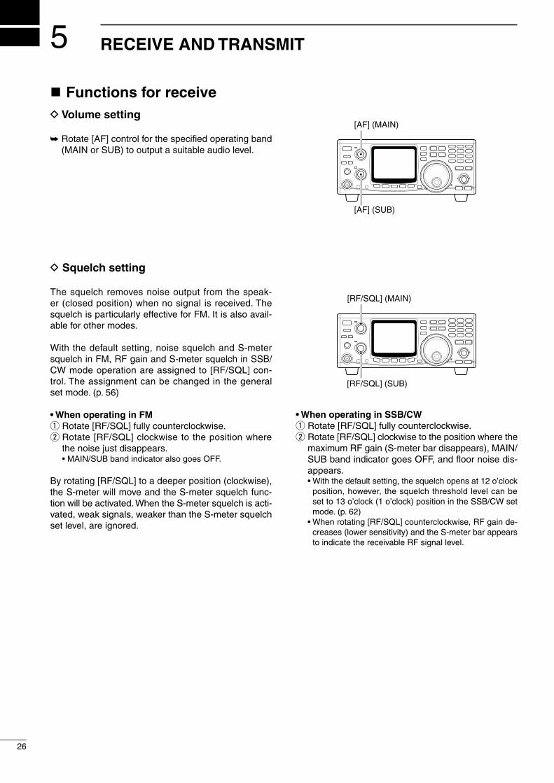
n Functions for receiveD Volume setting
➥ Rotate [AF] control for the specified operating band (MAIN or SUB) to output a suitable audio level.
D Squelch setting
The squelch removes noise output from the speak-er (closed position) when no signal is received. The squelch is particularly effective for FM. It is also avail-able for other modes.
With the default setting, noise squelch and S-meter squelch in FM, RF gain and S-meter squelch in SSB/CW mode operation are assigned to [RF/SQL] con-trol. The assignment can be changed in the general set mode. (p. 56)
• When operating in FMq Rotate [RF/SQL] fully counterclockwise.w Rotate [RF/SQL] clockwise to the position where
the noise just disappears. •MAIN/SUBbandindicatoralsogoesOFF.
By rotating [RF/SQL] to a deeper position (clockwise), the S-meter will move and the S-meter squelch func-tion will be activated. When the S-meter squelch is acti-vated, weak signals, weaker than the S-meter squelch set level, are ignored.
[RF/SQL] (SUB)
[RF/SQL] (MAIN)
• When operating in SSB/CWq Rotate [RF/SQL] fully counterclockwise.w Rotate [RF/SQL] clockwise to the position where the
maximum RF gain (S-meter bar disappears), MAIN/SUBbandindicatorgoesOFF,andfloornoisedis-appears.
•Withthedefaultsetting,thesquelchopensat12o’clockposition, however, the squelch threshold level can be set to 13 o’clock (1 o’clock) position in the SSB/CW set mode. (p. 62)
•Whenrotating[RF/SQL]counterclockwise,RFgainde-creases (lower sensitivity) and the S-meter bar appears to indicate the receivable RF signal level.
5
26
RECEIVE AND TRANSMIT
[AF] (SUB)
[AF] (MAIN)

n RIT functionThe RIT (Receive Incremental Tuning) function com-pensates for off-frequencies of the communicating sta-tion without moving the transmit frequency.
The RIT function can be used for the MAIN band only. The function affects the MAIN band even when ac-cessing the SUB band.
q Push [RIT] to turn the RIT function ON. •“RIT”indicatorappears.w Rotate [RIT] control to cancel the off-frequencies. •Rotate[RIT]controltothecenterposition,aftercommu-
nication.e Push [RIT] to cancel the RIT function. •“RIT”indicatordisappears.
[RIT] control
[RIT] switch
D RIT variable rangeSSB/CWmode:±1.0kHzin10Hzsteps(±2.0kHzfor
optional 1200 MHz band)FMmode :±5.0kHzin50Hzsteps(±10.0kHz
for optional 1200 MHz band)
FM RIT
FM mode
RITUSB
RIT variable range is displayed for 2 sec. and then returns to frequency indication.
RIT variable range is displayed for 2 sec. and then returns to frequency indication.
SSB mode
27
5RECEIVE AND TRANSMIT
n IF shift functionThe IF shift function electronically changes the pass-band frequency of the IF (Intermediate Frequency) and cuts out higher or lower frequency components of the IF to reject interference. The function shifts the IF frequencyupto±1.2kHzin100HzstepsinSSB/CWmode. The IF shift is especially useful in SSB opera-tion and not available in FM mode.
The IF shift function can be used for the SUB band using the SUB tuning dial function (p. 24)
D MAIN band IF shift operationq Set the [SHIFT] control to its center position when
there is no interference.w Rotate the [SHIFT] control to adjust for minimum in-
terference signal level. •TheaudiotonemaychangewhiletheIFshiftisinuse.
Center positionMax. counter-clockwise position
Max. clockwise position
D SUB band IF shift operationq Assign the SUB band IF shift function to either [RIT]
or [SHIFT] control using the RIT/SHIFT set mode (p. 68).
w Push [RIT] for 1 sec. to turn the SUB tuning dial function ON.
•“RIT”indicatorflashes.e Rotate [RIT] or [SHIFT] control for a minimum inter-
ference signal level.r Push [RIT] to cancel the SUB tuning dial function. •“RIT”indicatordisappears. •Set[RIT]or[SHIFT]controltothecenterpositionafter
the communication.
In satellite operation mode, the SUB tuning dial function cannot be activated. Therefore, the [SHIFT] control acts as an IF shift for the receive band (dis-played in the upper area).

28
5 RECEIVE AND TRANSMIT
n AGC time constantThe AGC (Automatic Gain Control) controls receiver gain to produce a constant output level even when the received signal strength is varied by fading, etc. Use AGC slow for normal phone operation; AGC fast for re-ceiving data and searching for signals.
➥ Push [AGC] to switch the time constant between fast and slow.
•“FAGC”indicatorappearswhenAGCfastisselected. •TheAGCtimeconstantisfixedinFMmoderegardless
of the FAGC indicator.
The SUB band’s AGC is automatically selected as slow in SSB and fast in CW. AGC time constant cannot be changed in FM mode.
n AFC functionThe AFC (Automatic Frequency Control) automatically tunes the operating frequency when receiving an off-frequency signal or receiving signal shifts in FM or FM narrow mode.
➥ Push [AFC/NB] to turn the AFC function ON and OFF.
•“AFC”indicatorappearswhentheAFCfunctionisacti-vated.
When strong nearby signals are available, the AFC function may tune to those signals.
n FM center indicatorThe MAIN/SUB band indicators indicate the received signal deviation in FM mode. When an off-center sig-nalisreceived,theindicatorflashes.
When an off-center signal is received, rotate the tun-ing dial or use the RIT function to illuminate the indica-tor continuously.
The FM center indicator can be turned OFF using the FM set mode. (p. 61)
[AGC]
CW VFO A
FAGC
[AFC/NB]
FM VFO A
AFC
Flashes in 300 msec. intervals.

n AttenuatorThe attenuator prevents desired signals from distort-ing when very strong signals are near the desired fre-quency, or when very strong electric fields, such as from broadcasting stations are near from your loca-tion.
The attenuator can be set to both or either band sep-arately, and the attenuation level can be set for each band independently.
➥ Push [ATT] to turn the attenuator ON and OFF. •“ATT”indicatorappearswhentheattenuatorisactivated.
D Setting the attenuation levelqPush[M/S•BAND]or[SUB]toselect thedesired
band of the attenuation level to be set.w Push [SET] then [ATT] to enter the attenuator set
mode.e Rotate the tuning dial to select attenuation level. •Push[M-CL5]toreturntothedefaultvalue.r Push [SET] to exit the attenuator set mode.
NOTE: When using the noise blanker, received audio may be distorted if they are excessively strong.
n Simple band scopeThisfunctionallowsyoutovisually“sweep”anareasurrounding the set frequency for other signals. Detect-ed signals are indicated graphically on the S-meter.
q Set the operating frequency and mode.w Push [SWP 0] to turn the simple band scope func-
tion ON and OFF. •“SWP”indicatorflasheswhenthesimplebandscope
function is activated. •DetectedsignalsareindicatedusingtheS-meterand
“Z”indicator,displayedabovetheS-meter,showsthecenter frequency (displayed frequency).
•Thesignalavailabilityisdetectedbythenoisesquelchcondition (open or close).
e To monitor the detected signal, rotate the tuning dial tosettheappearing“dot”oftheS-metertobelowthe“Z”indicator.
•Thefrequencyreadoutshowsthedetectedsignalfre-quency.
D Setting sweeping time intervalq Push [SET] then [SWP 0] to enter the sweep set
mode.w Rotate the tuning dial to select sweeping time inter-
val. •Push[M-CL5]toreturntothedefaultvalue.e Push [SWP 0] to exit the sweep set mode.
29
5RECEIVE AND TRANSMIT
[ATT]
CW VFO A
ATT
[SWP 0]
FM V F O A
SWP
Indicates detected signals Sweep center
Shows 10 channels around the displayed frequency.
Attenuation levels 144 MHz/ 0–100% variable 430(440) MHz bands Approx. 15 dB attenuation
at 100% setting 1200 MHz band Approx. 20 dB fixed
(optional)

30
5 RECEIVE AND TRANSMIT
n Noise blanker When operating in SSB or CW mode, pulse-type noise may be received such as from car ignitions. In this case, the noise blanker eliminates such noise.
The noise blanker is effective on both the MAIN and SUB bands but cannot be used for FM, or non-pulse-type noise.
➥ Push [AFC/NB] to turn the noise blanker function ON and OFF.
•“NB”indicatorappearswhenthenoiseblankerisacti-vated.
•ThenoiseblankerturnsONorOFFforbothbandssi-multaneously.
When using the noise blanker, received audio may be distorted if the signals are excessively strong.
n Tone squelch operationThe tone squelch opens only when receiving a sig-nal with the same pre-programmed subaudible tone. You can silently wait for a call from group members using the same tone. You can check the tone frequen-cy using the tone scan function if desired. (p. 47)
qSelectthedesiredbandbypushing[M/S•BAND].w Push [FM] to select FM mode, then set the desired
frequency.ePush[CALL•T-SQL]for1sec.toactivatethetone
squelch. •“T-SQL”indicatorappears.r When the signal with correct tone is received, the
squelch opens and audio can be heard. •Whenasignalwithincorrecttoneornotoneisreceived,
the squelch does not open, however, the S-meter indi-cates the signal strength.
•Pushandhold[CHECK7]toopenthesquelchmanual-ly and keep pushing to monitor.
t Operate the transceiver in a normal way (push [PTT] to transmit; release [PTT] to receive).
yPush[CALL•T-SQL] for1sec. tocancel thetonesquelch.
•“T-SQL”indicatordisappears.
[SET] Tuning dial
[FM][CALL•T-SQL]
[DN Z]/[Y UP]
D Setting the tone squelch frequencyThe tone squelch frequencies can be independently set for each band.
qPush[M/S•BAND]toselectthebandforthetonesquelch frequency to be set.
w Push [SET] then [FM] to enter the FM set mode.e Push [DN Z] or [Y UP] to select tone squelch fre-
quency item.r Rotate the tuning dial to select the desired tone
squelch frequency.t Push [FM] to exit from the FM set mode.
Tone frequency list unit:Hz
FM VFO A
T-SQL
67.069.371.974.477.079.782.5
085.4088.5091.5094.8097.4100.0103.5
107.2110.9114.8118.8123.0127.3131.8
136.5141.3146.2151.4156.7159.8162.2
165.5167.9171.3173.8177.3179.9183.5
186.2189.9192.8196.6199.5203.5206.5
210.7218.1225.7229.1233.6241.8250.3
254.1
[AFC/NB]
CW VFO A
NB

31
5RECEIVE AND TRANSMIT
n Optional DSP functionsTo activate the following functions, the optional DSP unit, UT-106, must be installed for both or either the MAIN and/or SUB bands.
D NR (Noise Reduction) functionThis function reduces noise components and picks out desired signals which are buried in noise. The received audio signals are converted to digital signals and then the desired signals are separated from the noise. The noise reduction function is available for all operating modes.
qPush[M/S•BAND]or[SUB]toselectthebandyouwish to activate, if required.
wPush[AFC/NB•NR]for1sec.toturnthenoisere-duction function ON and OFF.
•“NR”indicatorappearswhiletheautomaticnotchfilterisactivated.
[AFC/NB•NR] for 1 sec.
D Setting the noise reduction levelqPush[SET]then[AFC/NB•NR]toenterthenoise
reduction set mode.w Rotate the tuning dial to select the desired noise re-
duction level. •Push[M-CL5]for1sec.toreturntothedefaultvalue.ePush[AFC/NB•NR]toexitfromthenoisereduction
set mode.
USB VFO A
NR
D ANF (Automatic Notch Filter) functionThis function automatically attenuates beat tones, tun-ing signals, etc., even if they are moving. The automat-ic notch filter functions in SSB/FM modes.
qPush[M/S•BAND]or[SUB]toselectthebandyouwish to activate, if required.
wPush[AGC•ANF]for1sec.toturntheautomaticnotch filter function ON and OFF.
•“ANF”indicatorappearswhiletheautomaticnotchfilteris activated.
[AGC•ANF] for 1 sec.
USB VFO A
ANF
Unwanted tone frequency
Desired signal (AF)
Desired signal (AF)
Particular frequencyis attenuated
Auto notch OFF Auto notch ON
optional UT-106

32
5 RECEIVE AND TRANSMIT
n Functions for transmitD Output powerThe transmit output power can be continuously adjust-ed with [RF PWR].
Available power 144MHzband :5–100W 430(440)MHzband :5–75W 1200MHzband :1–10W(optional)
NOTE: To prevent interference, listen on the fre-quency to make sure the frequency is clear before transmitting by pushing [CHECK 7].
[RF PWR]
n Transmission via microphone
When transmitting with a microphone, push [PTT] and speak into the microphone at a normal voice level.
To maximize the readability of your transmitted sig-nal (voice), pause a few sec. after pushing [PTT]. Do not hold the microphone too close to your mouth.
D Microphone gainRotate [MIC GAIN] clockwise to increase, counter-clockwise to decrease the microphone gain.
9–12 o’clock position is recommended for [MIC GAIN].
[PTT] switch
HM-12
n Indications during transmitD Transmit indicatorThe MAIN band indicator lights red while transmitting. However, the SUB band indicator lights red during sat-ellite operation.
D RF power indicatorThe S-meter for the MAIN band is used as the RF power indicator to indicate the relative output power level. However, the S-meter for the SUB band is used as the RF power indicator during satellite operation.
D Time-out timerThe time-out timer limits the continuously transmitta-ble time period, and is selectable from 3, 5, 10, 20, 30 min. and OFF in TRANSMIT set mode. (p. 66)
D PTT lock functionDeactivate [PTT] and [TRANSMIT] switches. The func-tion can be switched ON and OFF in TRANSMIT set mode. (p. 66)
S-meter while receivingRF power indicator while transmitting
FM VFO A
VFO AFM
S 1 3 5 7 9 20 40 60dB
60dBO V E R
S 1 3 5 7 9 20 40
O V E R

33
5RECEIVE AND TRANSMIT
n FM mode operationqPush[M/S•BAND]toselectthedesiredband.w Push [FM] to select FM mode. •“FM”indicatorappears. •Push[FM]againtoselectrepeateroperationafterFM
modeselection.“DUP–”and“T”indicatorsappear. •Push[FM]for1sec.toselectFMnarrowmodeafterFM
modeselection.“FMN”indicatorappears.e Rotate the tuning dial to set the desired frequency.r Push [PTT] to transmit. •TheMAINbandindicatorlightsred.
t Speak into the microphone at a normal voice level. •Settingthe[MICGAIN]controlto10–12o’clockisrec-
ommended.y Release [PTT] to receive.
Tuning dial
[FM][M/S•BAND][TRANSMIT]
[MIC GAIN]
n VOX operation (for SSB and FM)
The VOX (Voice-operated Transmission) function switches between transmit and receive with your voice. This function provides an opportunity to input log en-tries into your computer, etc., while operating.
qPush[M/S•BAND]toselectthedesiredband.w Push either [SSB/CW] or [FM] to select phone
mode (USB, LSB or FM).e Push [VOX] to switch the VOX function ON and
OFF. •“VOX”indicatorappearswhiletheVOXfunctionisacti-
vated.
D Adjusting the VOX gainq Push [SET] then [VOX] to enter the VOX set mode.w Push [DN Z] or [Y UP] to select the VOX gain item. •“GAIn”isdisplayed.e Rotate the tuning dial to adjust the VOX gain while
speaking into the microphone at a normal voice level, until the transceiver begins transmitting.
•Withtoosensitiveasetting,thetransceivermaytrans-mit with other than your voice, such as noise, receiving signal, etc.
•Push[M-CL5]for1sec.toreturntothedefaultvalue.r Push [VOX] to exit VOX set mode.
D Adjusting the anti-VOX gainq Push [SET] then [VOX] to enter the VOX set mode.w Push [DN Z] or [Y UP] to select anti-VOX gain
item. •“Anti”isdisplayed.e Rotate the tuning dial to adjust the anti-VOX gain
while receiving a signal with a suitable audio output level, to the point where the transceiver does not transmit with the audio output from the speaker.
•Push[M-CL5]for1sec.toreturntothedefaultvalue.r Push [VOX] to exit VOX set mode.
D Adjusting the VOX delayq Push [SET] then [VOX] to enter the VOX set mode.w Push [DN Z] or [Y UP] to select the VOX delay
item. •“dELAy”isdisplayed.e Rotate the tuning dial to adjust the VOX delay time
while speaking into the microphone at a normal speed, to a convenient interval before returning to receive.
•Push[M-CL5]for1sec.toreturntothedefaultvalue.r Push [VOX] to exit VOX set mode.

34
5 RECEIVE AND TRANSMIT
n Repeater operationA repeater amplifies received signals and re-transmits them at a different frequency. When using a repeater, the transmit frequency is shifted from the receive fre-quency by an offset frequency.
D Setting the auto repeater range (U.S.A. and Korea versions only)
The auto repeater function automatically turns ON the duplex operation with specified shift direction and tone encoder when the operating frequency is set in the de-sired frequency range. To activate the auto repeater function, the following operations are necessary.
q Set one edge frequency of the desired frequency range.
•Push[M/S•BAND]toselectthedesiredbandifrequired. •Push[FM]toselectFMmodeifrequired.w Set the desired repeater conditions. •Bothone-touchrepeaterandmanualrepeatersetting
are acceptable.e Push [DN Z] or [Y UP] to select the memory chan-
nel 1. •Thememorychannel3or5isalsoacceptable.r Push [MW 4] for 1 sec. to program the contents into
the memory. •3beeptonesmaysound.t Set the other side edge frequency of the desired
frequency range.y Push [Y UP] to select the memory channel 2. •Selectmemorychannel4or6,respectivelyifthemem-
ory channel 3 or 5 is selected in step e.u Push [MW 4] for 1 sec. to program the contents into
the memory.i Repeat steps q to u to program other ranges.o Push [POWER] for 1 sec. to turn the power OFF
once, then push [POWER] to turn the power ON while pushing and holding [FM] and [TONE].
•Thememorychannelscanbeusedfornormaloperationafter programming.
!0 Push [SET] then [FM] to enter the FM set mode. !1 Push [DN Z] or [Y UP] to select auto repeater item. •“AutorPt”isdisplayed.!2 Rotate the tuning dial to turn the auto repeater func-
tion ON. U.S.A.version: •“on1” Activatesduplexonly. •“on2” Activatesduplexandtone. •“oFF” AutorepeaterfunctionisturnedOFF. Koreaversion: •“ON” Activatesduplexandtone. •“OFF” AutorepeaterfunctionisturnedOFF.!3 Push [FM] to exit from the FM set mode.
NOTE: All repeater ranges for available bands must be programmed at the same time. Otherwise, the previously programmed ranges will be lost.
D Frequency range and shift direction• U.S.A. version
FREQUENCY RANGE SHIFT DIRECTION
145.2000– 145.4999 MHz146.6100– 146.9999 MHz
“DUP–” appears
147.0000– 147.3999 MHz “DUP+” appears
442.0000– 444.9999 MHz “DUP+” appears
447.0000– 449.9999 MHz “DUP–” appears
1282.0000–1295.9999 MHz “DUP–” appears
• Korea version
FREQUENCY RANGE SHIFT DIRECTION
1439.0000–1440.0000 MHz “DUP–” appears
1290.0000–1293.0000 MHz “DUP–” appears
D Setting the shift direction for the one-touch repeater function (except Europe, Sweden and Italy versions)
qPush[M/S•BAND]or[SUB]toselect thedesiredfrequency band.
w Push [SET] then [FM] to enter the FM set mode.e Push [DN Z] or [Y UP] to select shift direction item. •“o_touch”and“rPt”aredisplayed.r Rotate the tuning dial to select the desired direction. •“DUP–”or“DUP+”isselectable.t Push [FM] to exit from the FM set mode.

35
5RECEIVE AND TRANSMIT
D Using the one-touch repeater function (except Europe, Sweden and Italy versions)
By using the pre-programmed offset frequency, shift direction and tone frequency, quick and simple repeat-er operation can be made.
The default values for offset frequency and direction areasfollows:144MHzband :–0.600MHz430(440)MHzband:–5.000MHz1200MHzband :–20.000MHz(optional)Tonefrequency :88.5Hz
qPush[M/S•BAND]toselectthedesiredfrequencyband.
w Push [FM] to select FM mode.e Rotate the tuning dial to input the desired repeater
frequency. •Directfrequencyinputusingthekeypadcanbeusedfor
frequency setting.
FM VFO A
r Push [FM] to select the repeater operation mode. •“DUP–”and“T”indicatorsappear.
FM DUP VFO A
T
t Push [PTT] to access the repeater.
FM DUP VFO A
T60dBS 1 3 5 7 9 20 40
Shifts 5 MHz when transmitted.
y Release [PTT] to receive a signal from the repeater.u Push [FM] to cancel the duplex operation mode. •“DUP–”and“T”indicatorsdisappear.
FM VFO A
D Setting tone frequency (except Europe, Sweden and Italy versions)
qPush[M/S•BAND]toselectthedesiredfrequencyband.
w Push [SET] then [FM] to enter the FM set mode.e Push [DN Z] or [Y UP] to select the tone frequency
item. •“ton,”selectedband(144/430(440)/1200)and“T”indica-
tor appear. r Rotate the tuning dial to set the desired tone fre-
quency.t Push [FM] to exit from the FM set mode.
D Setting offset frequencyqPush[M/S•BAND]or[SUB]toselect thedesired
frequency band.w Push [SET] then [FM] to enter the FM set mode.e Push [DN Z] or [Y UP] to select the offset frequen-
cy item. •“duP”andselectedband(144/430(440)/1200)appear.r Rotate the tuning dial to set the desired tone fre-
quency.t Push [FM] to exit from the FM set mode.
D Manual repeater settingq Set the desired frequency. •Push[M/S•BAND]toselectthedesiredbandifrequired. •Push[FM]toselectFMmodeifrequired.wPush[SPLIT•DUP]for1sec.toselecttheduplex
operation and the shift direction. •“DUP–”or“DUP+”indicatorappears,dependingonthe
selection. •Set the offset frequency in the FM set mode, if required.
e Push [TONE] to activate the tone encoder. •“T”indicatorappears. •SetthetonefrequencyintheFMsetmode,ifrequired
for non-European versions.. •1750HztoneistransmittedforEurope,Swedenand
Italy versions.rPush[SPLIT•DUP]for1sec.and[TONE]tocancel
the duplex operation and deactivate the tone en-coder.
•“DUP–”or“DUP+”and“T”indicatorsdisappear.

36
5 RECEIVE AND TRANSMIT
n SSB mode operationqPush[M/S•BAND]toselectthedesiredfrequency
band.w Push [SSB/CW] to select USB or LSB mode.
•Push[SSB/CW]for1sec.toswitchbetweenUSBandLSB when either the USB or LSB has been selected.
e Rotate the tuning dial to set the desired frequency.r Push [PTT] to transmit and speak into the micro-
phone at a normal voice level.t Rotate [MIC GAIN] so that the MAIN band indicator
periodically lights red brightly.•ThebrightnessincreaseswhentheALCisactivated.
y Release [PTT] to receive.
Tuning dial
[SSB/CW][M/S•BAND][TRANSMIT]
[MIC GAIN]
n Speech compressorThe speech compressor increases average RF out-put power, improving signal strength and readability in SSB. The IC-910H has a built-in, low-distortion speech compressor circuit.
➥ Push [COMP] to turn the speech compressor ON and OFF.
•EitherUSBorLSBshouldbeselected. •“COMP”indicatorappearswhenthespeechcompres-
sor is activated.
[MIC GAIN]
[COMP]MAIN band LED lights in red while transmitting.
D Compression level settingq Select USB or LSB mode.wPresetthetransceiverasfollows: [COMP]function :OFF [RFPOWER]control :Max.counterclockwisee Transmit at your normal voice level.r Adjust the [MIC GAIN] control so that the MAIN
band indicator periodically lights red brightly wheth-er or not you speak softly or loudly.
t Push [COMP] to turn the speech compressor ON.y Push [SET] then [COMP] to enter the COMP set
mode.u Rotate the tuning dial to adjust the compression
level to the point where the maximum value and the MAIN band indicator brightness does not increase, whether or not you speak softly or loudly.
•WhentheMAINbandindicatorcontinuouslylightsredwith increased brightness, your transmitted voice may be distorted.
•It’sagoodideatoadjustthecompressorlevelbymon-itoring with an other transceiver or receiver, if you have one, or with an other station.
i Push [COMP] to exit the COMP set mode.
ALC indicator While transmitting, the MAIN/SUB band indicator shows the ALC condition. Brightness increases more than usual when the ALC function is activated.
VOX function The VOX (Voice-operated Transmission) function is available for switching between transmit and receive with your voice. See p. 33 for details.

37
5RECEIVE AND TRANSMIT
n Split frequency operationSplit frequency operation allows you to transmit and receive on two different frequencies in the same fre-quency band. Split frequency operation uses 2 fre-quencies, one in VFO A and the other in VFO B.
q Set a receive frequency in VFO mode. •EitherVFOAorVFOBcanbeused.w Push [A=B 2] for 1 sec. •TheundisplayedVFOcontentsareclearedandequal-
ized to the displayed frequency.e To change the receive frequency, rotate the tuning
dial.
USB VFO A
r To replace the transmit and receive frequencies, push [A/B 3].
USBVFO B
t To change the transmit frequency, rotate the tuning dial while pushing [CHECK 7].
y Push [SPLIT]. •“SPLIT”indicatorappears. •NowyoucanreceiveonthedisplayedVFOandtransmit
on the undisplayed VFO. •Tomonitorthetransmitfrequency,push[CHECK7].
USB SPLITVFO B
u Push [SPLIT] to cancel the split frequency opera-tion.
•“SPLIT”indicatordisappears.
[A=B 2]
[A/B 3]
[SPLIT][TRANSMIT]
Cross mode communication can be performed using the split function. (e.g. USB and CW)
n Full duplex operationThe MAIN and SUB bands are activated independent-ly, therefore, simultaneous transmission and reception in different frequency bands are possible.
qPush[M/S•BAND]toselectthedesiredfrequencyband for transmission.
•Push [V/M 1] to select VFO or memory mode, if desired. •Push[SSB/CW]or[FM]toselectthedesiredoperating
mode.w Rotate the tuning dial to set the desired frequency. •Direct frequency input from the keypad is also available.e Push [SUB] to enable the SUB band access. •Push[M/S•BAND]for1sec.toselectthedesiredfre-
quency band, if desired. (when the optional UX-910 is installed.)
•Push [V/M 1] to select VFO or memory mode, if desired. •Push[SSB/CW]or[FM]toselectthedesiredoperating
mode. r Push [PTT] to transmit.
• SUB band mute functionThe SUB band mute function mutes receiving audio from the SUB band while transmitting.
q Push [SET] then [TRANSMIT] to enter the TRANS-MIT set mode.
w Push [DN Z] or [Y UP] to select the SUB band mute item.
•“Audio”isdisplayed.e Rotate the tuning dial to turn the SUB band mute
function ON and OFF. •Push[M-CL5]for1sec.toreturntothedefaultsetting.r Push [TRANSMIT] to exit from the TRANSMIT set
mode.
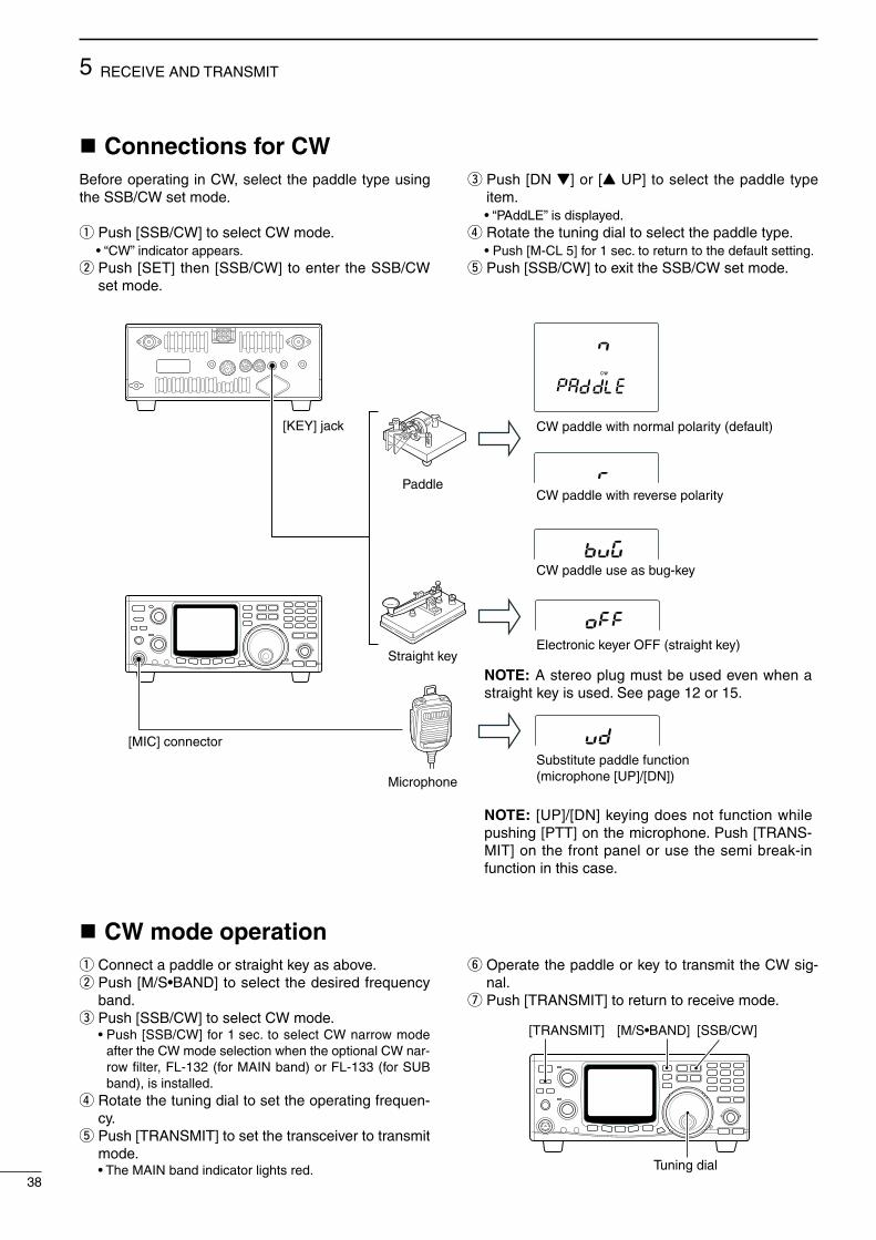
38
5 RECEIVE AND TRANSMIT
n Connections for CWBefore operating in CW, select the paddle type using the SSB/CW set mode.
q Push [SSB/CW] to select CW mode.•“CW”indicatorappears.
w Push [SET] then [SSB/CW] to enter the SSB/CW set mode.
e Push [DN Z] or [Y UP] to select the paddle type item.•“PAddLE”isdisplayed.
r Rotate the tuning dial to select the paddle type.•Push[M-CL5]for1sec.toreturntothedefaultsetting.
t Push [SSB/CW] to exit the SSB/CW set mode.
n CW mode operationq Connect a paddle or straight key as above.wPush[M/S•BAND]toselectthedesiredfrequency
band.e Push [SSB/CW] to select CW mode. •Push[SSB/CW]for1sec.toselectCWnarrowmode
after the CW mode selection when the optional CW nar-row filter, FL-132 (for MAIN band) or FL-133 (for SUB band), is installed.
r Rotate the tuning dial to set the operating frequen-cy.
t Push [TRANSMIT] to set the transceiver to transmit mode.
•TheMAINbandindicatorlightsred.
y Operate the paddle or key to transmit the CW sig-nal.
u Push [TRANSMIT] to return to receive mode.
Tuning dial
[SSB/CW][M/S•BAND][TRANSMIT]
CW
Paddle
Straight key
Microphone
[KEY] jack
[MIC] connector
CW paddle with normal polarity (default)
CW paddle with reverse polarity
CW paddle use as bug-key
Electronic keyer OFF (straight key)
Substitute paddle function(microphone [UP]/[DN])
NOTE: A stereo plug must be used even when a straight key is used. See page 12 or 15.
NOTE: [UP]/[DN] keying does not function while pushing [PTT] on the microphone. Push [TRANS-MIT] on the front panel or use the semi break-in function in this case.

39
5RECEIVE AND TRANSMIT
D Setting keying speedq Push [SET] then [SSB/CW] to enter the SSB/CW
set mode.w Push [DN Z] or [Y UP] to select the keying speed
item. •“SPEEd”isdisplayed.e Rotate the tuning dial to adjust the keying speed to
the desired speed. •Keyingspeedcanbeselectedfrom6–60wpm. •Push[M-CL5]for1sec.toreturntothedefaultvalue.r Push [SSB/CW] to exit the SSB/CW set mode.
D Setting semi break-in functionq Push [SET] then [SSB/CW] to enter the SSB/CW
set mode.w Push [DN Z] or [Y UP] to select the semi break-in
item. •“br-In”isdisplayed.e Rotate the tuning dial to turn the semi break-in func-
tion ON and OFF. •Push[M-CL5]for1sec.toreturntothedefaultsetting.r Push [DN Z] or [Y UP] to select the delay time item. •“dELAy”isdisplayed.t Rotate the tuning dial to set the delay time to the
desired time period. •Delay time can be selected from 2.0–13.0sec. in
0.1 sec. steps. •Push[M-CL5]for1sec.toreturntothedefaultvalue.y Push [SSB/CW] to exit the SSB/CW set mode.
D Setting keying weightq Push [SET] then [SSB/CW] to enter the SSB/CW
set mode.w Push [DN Z] or [Y UP] to select the keying weight
item. •“rAtio”isdisplayed.e Rotate the tuning dial to adjust the keying weight
ratio to the desired level. •Keyingweight ratio canbe selected from1:1:2.8 to
1:1:4.5. •Push[M-CL5]for1sec.toreturntothedefaultvalue.r Push [SSB/CW] to exit the SSB/CW set mode.
D Setting CW pitchq Push [SET] then [SSB/CW] to enter the SSB/CW
set mode.w Push [DN Z] or [Y UP] to select the CW pitch item. •“Pitch”isdisplayed.e Rotate the tuning dial to adjust the CW pitch to the
desired pitch. •CWpitchcanbeadjustedwithin300–900Hzrange. •Push[M-CL5]for1sec.toreturntothedefaultvalue.r Push [SSB/CW] to exit the SSB/CW set mode.
D Setting side toneq Push [SET] then [SSB/CW] to enter the SSB/CW
set mode.w Push [DN Z] or [Y UP] to select the side tone item. •“SidE-t”isdisplayed.e Rotate the tuning dial to adjust the side tone level to
the desired level. •Push[M-CL5]for1sec.toreturntothedefaultvalue.r Push [SSB/CW] to exit the SSB/CW set mode.
KEYING WEIGHT EXAMPLE: Morse code “K”
DASH
Weight setting:
1:1:3 (default)
Weight setting:
Adjusted
DASHDOT
(Fixed*)
Adjustable range SPACE (Fixed*)
*SPACE and DOT length can be adjusted with the keying speed only.

6
40
MEMORY OPERATION
n Memory channelsThe IC-910H has 106 memory channels (99 for regu-lar, 6 scan edges and 1 call) and they are equipped for each frequency band for storing the most often used frequencies and operating mode, as well as tone fre-quency, offset frequency, etc.
n Operation on a memory channel
Frequency and mode, etc., can be changed in a mem-ory channel. However, they will be cleared if [MW 4] is not pushed.
D Memory channel selectionq Push [V/M 1] to select memory channel mode. •“MEMO”indicatorappears.w Push [DN Z] or [Y UP] to select the desired mem-
ory channel. •Memorychannelchangescontinuouslywhileholding
[DN Z] or [Y UP]. •Thetuningdialrotationwhilepushing[F-INPENT]also
selects memory channel.e Push [V/M 1] to return to VFO mode.
D During VFO mode operation By pushing [DN Z] or [Y UP] during VFO mode op-eration, memory channel is also selectable. However, the frequency readout does not change in this case, only the memory channel number changes.
[Y UP][DN Z]
FM VFO A
MEMO
FM
MEMO
USB
Select memory mode
Select memorychannel
Memory Channel
1–99
1A/1b–3A/3b
C
Description
Regular memory channels. Programs operating frequency, mode, subaudible tone activity with frequency and split/du-plex conditions.
Scan edge channels. Programs edge fre-quencies for programmed scan.
Call channel recalls a specified frequen-cy on the instant. Programs operating frequency, mode, etc., and is available for each band, independently.

41
6MEMORY OPERATION
n Programming in VFO modeMemory channel programming can be performed ei-ther in VFO mode or in memory mode.
q Set the desired operating frequency and mode in VFO mode.
•Push[V/M1]toselectVFOmode,ifrequired. •Tonefrequency,offsetfrequency,etc.,canalsobepro-
grammed. •Inputthefrequencyfromthekeypad
Push [F-INP ENT] ⇒ [1] ⇒ [4] ⇒ [4] ⇒ [.] ⇒ [2] ⇒ [6] ⇒ [8] ⇒ [F-INP ENT]
w Push [DN Z] or [Y UP] to select the desired mem-ory channel to be programmed.
e Push [MW 4] for 1 sec. to program the displayed fre-quency and operating mode into the memory chan-nel.
To check the programmed contents, push [V/M 1] to select memory mode.
FM VFO A
USB VFO A
USB
USB
VFO A
VFO A
Select desired memory channel.
Beep tones sound.
Set desired frequencyand mode.
n Programming in memory mode
q Push [V/M 1] to select memory mode.w Push [DN Z] or [Y UP] to select the desired mem-
ory channel to be programmed. •Thetuningdialrotationwhilepushing[F-INPENT]also
selects memory channel.e Set the desired operating frequency and mode in
the memory mode. •Tonefrequency,offsetfrequency,etc.,canalsobepro-
grammed. •Setthedesiredoperatingfrequencyusingwiththekey-
pad when programming into blank channels. The tuning dial rotation for frequency setting cannot be performed when a blank channel is selected.
•Inputthefrequencyfromthekeypad Push [F-INP ENT] ⇒ [1] ⇒ [4] ⇒ [4] ⇒ [.] ⇒ [1] ⇒ [6] ⇒ [4] ⇒ [F-INP ENT]
r Push [MW 4] for 1 sec. to program the displayed fre-quency and operating mode into the memory chan-nel.
MEMO
FM
MEMO
USB
MEMO
USB
MEMO
USB
Set desired frequencyand mode.
Beep tones sound.
Select desired memory channel.

42
6 MEMORY OPERATION
n Blank channelsMemory channels 6–99 are blank channels by factory default. They have no contents programmed.
Whenablankchannelisselected,the“BLANK”indica-tor appears and the frequency band is displayed 2 sec. after the selection.
MEMO
BLANK
MEMO
BLANK
Operating band appears after 2 sec.
“--430-” appears while in 430 MHz band.“-1200-” appears while in 1200 MHz band.
D Programming a blank channelq Push [V/M 1] to select VFO mode.w Set the desired operating frequency, mode, etc.e Push [MW 4] for 1 sec. to program the memory
channel. •“BLANK”indicatordisappears.
n Frequency transferringThe frequency and operating mode in a memory chan-nel can be transferred to the VFO.
Frequency transferring can be performed in either VFO mode or memory mode.
D Transferring in memory modeThis is useful for transferring frequency and operating mode while operating in memory mode.
When you have changed the frequency or operating modeintheselectedmemorychannel:•Displayed frequency and mode are transferred.•Programmed frequency and mode in the memo-
ry channel are not transferred, and they remain in the memory channel.
q Push [DN Z] or [Y UP] to select the memory chan-nel to be transferred in memory mode.
•And,setthefrequencyoroperatingmodeifrequired.w Push [M≈V 6] for 1 sec. to transfer the frequency
and operating mode. •Displayed frequencyandoperatingmodeare trans-
ferred to the VFO.e Push [V/M 1] to return to VFO mode.
D Transferring in VFO modeThis is useful for transferring programmed contents to VFO.
q Push [V/M 1] to select VFO mode.w Push [DN Z] or [Y UP] to select the memory chan-
nel to be transferred. •“BLANK”appearsiftheselectedmemorychannelisa
blank channel. In this case transferring is impossible.e Push [M≈V 6] for 1 sec. to transfer the frequency
and operating mode. •Transferredfrequencyandoperatingmodeappearon
the frequency readout.
MEMO
USB
MEMO
USB
USB VFO A
Beep tone sounds.
Select VFO mode.

43
6MEMORY OPERATION
n Memory clearingAny unnecessary memory channels can be cleared. The cleared memory channels become blank chan-nels.
q Push [V/M 1] to select memory mode.w Push [DN Z] or [Y UP] to select the desired mem-
ory channel to be cleared.e Push [M-CL 5] for 1 sec. to clear the contents. •Theprogrammedfrequencyandoperatingmodedisap-
pear. •“BLANK”indicatorappears.r To clear other memory channels, repeat steps w
and e.
MEMO
USB
MEMO
BLANK
Operating band appears after 2 sec.
MEMO
BLANK
Beep tone sounds.
n Call channelThe call channel is a one-touch accessible channel for recalling your most-often-used frequency. The IC-910H has one call channel for each frequency band.
D Call up a call channel
qPush[M/S•BAND]or[SUB]toselect thedesiredfrequency band.
w Push [CALL] to select the call channel.e Push [CALL] or [V/M 1] to return to previous display.
D Call channel programming
qPush[M/S•BAND]or[SUB]toselect thedesiredfrequency band.
w Push [CALL] to select the call channel.e Enter the desired frequency using the keypad. e.g.; When programming 145.8200 MHz. Push [F-INP ENT] ⇒ [1] ⇒ [4] ⇒ [5] ⇒ [.] ⇒ [8] ⇒
[2] ⇒ [F-INP ENT] •Selectoperatingmodeifrequired.r Push [MW 4] for 1 sec. to program the call channel.
D Transferring call channel contents
qPush[M/S•BAND]or[SUB]toselect thedesiredfrequency band.
w Push [CALL] to select the call channel.e Push [M≈V 6] for 1 sec. to transfer the call channel
contents.
FM
USB VFO A
BLANK

44
6 MEMORY OPERATION
n Memo padsThe IC-910H has a memo pad function for each fre-quency band to store frequency and operating mode for easy write and recall. The memo pads are separate from memory channels.
The default number of memo pads is 5, however, this can be increased to 10 in the memo pad set mode (p. 64) if desired.
Memo pads are convenient when you want to memo-rize a frequency and operating mode temporarily, such as when you find a DX station in a pile-up, or when a desired station is busy for a long time and you want to temporarily search for other stations.
Use the transceiver’s memo pads instead of relying on hastily scribbled notes that are easily misplaced.
D Writing frequencies and operating modes into memo pads
You can simply store the accessed readout frequency and operating mode by pushing [MPW 8].
When you write a 6th (or 11th) frequency and operat-ing mode, the oldest written frequency and operating mode are automatically erased to make room for the new settings.
Each memo pad must have its own unique combi-nation of frequency and operating mode; memo pads having identical settings cannot be written.
D Calling up a frequency from a memo padYou can simply call up the desired frequency and op-erating mode of a memo pad by pushing [MPR 9].•BothVFOandmemorymodescanbeused.•Thefrequencyandoperatingmodearecalledup,starting
from the most recently written.
CW
FM
USB
FM
USBFM VFO A
VFO or memory mode Memo pad contents
CW
FM
USB
FM
USB
VFO or memory mode Memo pad contents
When [MPW 8] is pushed, “FM 145.9200 MHz” is programmed and the oldest memo pad is cleared.
Cleared
FM VFO A

7
45
SCANS
n Scan typesScanning searches for signals automatically and makes it easier to locate new stations for contact or lis-tening purposes. The IC-910H has several scan types; programmed scan, memory scan and mode select scan.
The scanning operation can be performed indepen-dently for MAIN and SUB band. And to search a sub-audible tone frequency for a repeater frequency, a tone scan is also available.
n Preparation• Squelch conditionSet the [RF/SQL] control as for regular operation.
• When receiving a signal•Scanpauses for10sec.when receivingasignal,
then resumes.•Whenasignaldisappearswhilescanispaused,scan
resumes approx. 3 sec. later.
• Scan resume ON/OFFYou can select the scan to resume or cancel when re-ceiving a signal, in the scan set mode. Scan resume ON/OFF must be set before operating a scan. See de-tails described at right for ON/OFF setting.
• Scan start/stop operationPush [SCAN .] to start and cancel scanning.
• Scan speedScan speed can be selected from 2 levels, high (de-fault) or low, in the scan set mode. See details de-scribed at right.
• Setting scan resume conditionq Push [SET] then [SCAN .] to enter the scan set
mode.w Push [DN Z] or [Y UP] to select the scan resume
item. •“SC-rES”isdisplayed.e Rotate the tuning dial to select scan resume condi-
tion from ON and OFF. •“ON”:scanresumes,“oFF”:scancancels •Push[M-CL-5]for1sec.toreturntothedefaultsetting.r Push [SCAN .] to exit from the scan set mode.
• Setting scan speedq Push [SET] then [SCAN .] to enter the scan set
mode.w Push [DN Z] or [Y UP] to select the scan speed
item. •“SC-SPd”isdisplayed.e Rotate the tuning dial to select scan resume condi-
tion from HI and Lo. •Push[M-CL-5]for1sec.toreturntothedefaultsetting.r Push [SCAN .] to exit from the scan set mode.
MEMORY SCANRepeatedly scans all programmed memory channels. This scan operates in memory mode.
M-CH 1 M-CH 5
M-CH 2 M-CH 3 M-CH 4
M-CH 6M-CH 7M-CH 99
Call channels and scan edge channels are not scanned.
Blank
PROGRAMMED SCANRepeatedly scans between two scan edge frequencies (scan edge memory channels 1A/2A/3A and 1b/2b/3b).This scan operates in VFO mode.
Scan starts from the displayed frequency or the lower scan edge frequency.
Scan
Scan edge(1A/2A/3A)
Scan edge(1b/2b/3b)
Jump
MODE SELECT SCANRepeatedly scans all selected mode memory channels. This scan operates in memory mode.
FM FM
USB FM CW
USBFMFM

46
7 SCANS
n Programmed scan operationScans specified frequency range, programmed in the memory channel 1A/1b, 2A/2b and 3A/3b. Before start-ing the programmed scan, scan edges should be pro-grammed in these channels.
D Selecting scanning rangeqPush[M/S•BAND]or[SUB]toselect thedesired
frequency band to be scanned.w Push [SET] then [SCAN .] to enter the scan set
mode.e Push [DN Z] or [Y UP] to select the programmed
scan item. •“P-SCAn”isdisplayed.r Rotate the tuning dial to select the desired scan-
ning range from 1A-1b, 2A-2b and 3A-3b. •Push[M-CL5]for1sec.toreturntothedefaultsetting.t Push [SCAN .] to exit from the scan set mode.
wSelect mode.
qSelect VFOmode.
eStart.rStop.
D Starting the programmed scanqPush[M/S•BAND]or[SUB]toselect thedesired
frequency band to be scanned.w Push [V/M 1] to select VFO mode.e Select the desired operating mode. •Theoperatingmodecanalsobechangedwhilescan-
ning.r Push [SCAN .] to start the programmed scan. •“SCAN”indicatorflashes. •Thetuningstepsettingisusedforthescanningstep. •1kHzor1MHztuningstepcanalsobeusedasthe
scanning step.t Push [SCAN .] to cancel the scan.
If the same frequency is programmed into the scan edge memory channel 1A and 1b, 2A and 2b or 3A and 3b, programmed scan does not start.
FM VFO A
60dB
SCAN
S 1 3 5 7 9 20 40
Flashes while scanning
n Memory scan operationScans programmed memory channels only. Blank channels and programmed scan edge channels (1A/1b, 2A/2b and 3A/3b) are not scanned.
qPush[M/S•BAND]or[SUB]toselect thedesiredfrequency band to be scanned.
w Push [V/M 1] to select memory mode.e Push [SCAN .] to start the memory scan. •“SCAN”indicatorflashes. •Pushing [SPCH•LOCK] for 1sec. during scan starts
modeselectscanand“LOCK”indicatorappears.(p.47)r Push [SCAN .] to cancel the scan.
qSelect memorymode.
wStart.eStop.
MEMO
60dB
SCAN
S 1 3 5 7 9 20 40
Flashes while scanning

47
7SCANS
n Mode select scanScans the memory channels, desired operating mode is programmed, only.
qPush[M/S•BAND]or[SUB]toselect thedesiredfrequency band to be scanned.
w Push [V/M 1] to select memory mode.e Push [SSB/CW] or [FM] to select the desired oper-
ating mode to be scanned. •Theoperatingmodecanalsobechangedduringscan.rPush[SPCH•LOCK]for1sec. •“LOCK”indicatorappears.t Push [SCAN .] to start the mode select scan. •“SCAN”indicatorflashes.y Push [SCAN .] to cancel the scan.
wSelect mode.
qSelect memorymode.
e appears. rStart.tStop.
LOCK
MEMO
USB
VFO AFM
LOCKS 1 3 5 7 9 20 40 60dB
60dB
SCAN
S 1 3 5 7 9 20 40
Flashes while scanning
n Tone scanThe transceiver can detect a subaudible tone frequen-cy in a received signal. By monitoring a signal that is being transmitted on a repeater input frequency, you can determine the tone frequency required to access the repeater.
q Set the desired frequency or memory channel to be checked for a tone frequency.
w Push [FM] to select FM mode.ePush[TONE]or[CALL•T-SQL]for1sec.toactivate
the subaudible tone. •“T”or“T-SQL”indicatorappears.r Push [SCAN .] for 1 sec. to start the tone scan. •“SCAN”indicatorflasheswhilescanning. •Scanstopswhenasubaudibletoneisdetected. •Scanbecomesslowerorquicker,respectivelywhenthe
noise squelch is open or closed.t Push [SCAN .] for 1 sec. to cancel the scan.
NOTE: The tone scan automatically changes tone frequency setting to the detected tone frequency.
qSelect FM mode.
wStart.eStop.
FM VFO A
60dB
SCAN
S 1 3 5 7 9 20 40
Flashes while scanning
SQLT-

8
48
SATELLITE OPERATION
n Satellite communications outlineBoth satellite mode B (435 MHz uplink, 145 MHz down-link) and mode J (145 MHz uplink, 435 MHz downlink) can be operated from the IC-910H, and mode L can be operated when the optional UX-910 1200 MHz BAND
UNIT is installed.
Satellite communications is possible only when a sat-ellite is in view and its transponder is activated.
n Satellite notes1. NEVER set the output power too high. Too much
power will shorten the satellite’s life. Set your transmit power so that your downlink sig-
nal level is lower than the beacon’s signal level.
2. Confirm a satellite’s operating mode in advance through documentation (magazines, etc.) or via ap-propriate satellite tracking software. In the wrong mode, you cannot use the satellite even if you re-ceive its beacon signal.
3. Preamplifiers may be necessary to receive satel-lite signals. Optional AG-25, AG-35 and AG-1200 (for UX-910) are available to use with the IC-910H. (p. 16)
4. When you use a reverse tracking satellite in SSB mode, use the LSB for the uplink frequency and USB for the downlink frequency.
•WhenusinganormaltrackingsatelliteinSSBmode,use USB for both the uplink and downlink frequencies.
n Entering into the satellite mode
Operating frequencies in satellite mode can be set both before and after entering into the satellite mode. Normal and reverse tracking are available.
D Transferring the VFO frequency to the satellite VFO
q Set the downlink frequency (receive) in the MAIN band.
w Set the uplink frequency (transmit) in the SUB band.
e Push [SATELLITE] for 1 sec. to transfer the frequen-cies, set in steps q and w, into the satellite VFO.
•Satellitemodeisautomaticallyselectedaftertransfer-ring.
•“SATL”indicatorwitheither“NOR”or“REV”indicatorap-pears.
•VFOandmemorymodeindicationsaredisplayedintheSUB band (lower area) during satellite mode.
[SATELLITE] for 1 sec.
435 MHz band
435 MHz band
145 MHz band145 MHz band
FUJI 3 (FO-29)UplinkDownlink
• Mode B operating diagram [Example]: FUJI 3 (FO-29), Mode B
•Uplinkfrequency: 145.9000–146.0000 MHz•Downlinkfrequency: 435.8000–435.9000 MHz•Trackingdirection: Reverse•CWbeaconfrequency: 435.7950 MHz
Orbit informationOrbit information describes satellite location, reach-ing angles, etc. This information may be available in ham magazines or organization issues, such as from ARRL, RSGB handbook, etc.
Appropriate satellite tracking software is also con-venient.

49
8SATELLITE OPERATION
n Setting the satellite VFOq Push [SATELLITE] to enter the satellite mode. •“SATL”indicatorwitheither“NOR”or“REV”indicatorap-
pears.w Push [V/M 1] to toggle satellite VFO and memory
mode. •VFOormemorymodeindicatorisdisplayedintheSUB
band (lower area).e Push [SCAN . M] to enable the downlink frequency
tuning. •Uplinkfrequencyindicationdisappears. •Rotatethetuningdialtosetthedownlinkfrequencyand
push [SSB/CW] to select the operating mode. •Push[SCAN.M] again after the tuning.
USB
MEMO
LSB
SATL
REV
S 1 3 5 7 9 20 40 60dB
60dBS 1 3 5 7 9 20 40
r Push [SWP 0 S] to enable the uplink frequency tuning.
•Downlinkfrequencyindicationdisappears. •Push[SWP0S] again after the tuning.
USB
MEMO
LSB
SATL
REV
S 1 3 5 7 9 20 40 60dB
60dBS 1 3 5 7 9 20 40
NOTE: To select the operating mode for the uplink, push [SUB] to enable the SUB band access.
n Tracking selection•Push[F-INPENTNOR ↔ REV] for 1 sec. to switch be-
tween normal and reverse tracking.
D Normal trackingBoth downlink and uplink frequencies increase or de-crease in the same step simultaneously by tuning dial rotation.
[SATELLITE]
[F-INP ENT]
D Reverse trackingThe downlink frequency follows the tuning dial rotation, however, the uplink frequency changes in the reverse direction to the tuning dial rotation in the same step.
USB
MEMO
LSBNOR
SATL
REV
S 1 3 5 7 9 20 40 60dB
60dBS 1 3 5 7 9 20 40
Satellite mode indicationVaries simultaneously

50
8 SATELLITE OPERATION
n Preparationq Decide on a usable satellite.w Confirm the approximate location of the satellite
andoperatingmode(e.g.“B,”“J,”etc.)throughdoc-umentation (magazine, etc.) or via appropriate sat-ellite tracking software.
e Set the antenna direction for the desired satellite.r Select satellite mode on the transceiver. •Push[SATELLITE]. •Push[F-INPENTNOR ↔ REV] for 1 sec. to select track-
ing mode if desired.t Select operating mode.
USB
MEMO
LSBNOR
SATL
REV
S 1 3 5 7 9 20 40 60dB
60dBS 1 3 5 7 9 20 40
Satellite mode indication Uplink (transmit) frequency
Downlink (receive) frequency
y Set the downlink frequency (MAIN band) to the bea-con frequency.
•Refertoahammagazineorbookfordetailedinforma-tion.
•AdjusttheantennadirectionsothattheS-metershowsto its strongest level.
•TheS-meterlevelshouldbenotedfortransmitpoweradjustment during a loop test.
USB
MEMO
USB
SATL
REV
S 1 3 5 7 9 20 40 60dB
60dBS 1 3 5 7 9 20 40
u Perform a loop test. •Setthedownlinkfrequency(MAINband)toavacantfre-
quency within the satellite’s coverage. •Push[SWP0S] then, set the uplink frequency (SUB
band) while transmitting a single tone such as a whistle to find your downlink signal and monitor your own signal correctly. Push [SWP 0 S] after setting.
USB
MEMO
LSB
SATL
REV
S 1 3 5 7 9 20 40 60dB
60dBS 1 3 5 7 9 20 40
NOTE: To avoid excessive power, set the output power so that the downlink signal strength is lower than the beacon’s strength.
USB
MEMO
LSB
SATL
REV
S 1 3 5 7 9 20 40 60dB
60dBS 1 3 5 7 9 20 40
i Set the desired frequency to begin your satellite communications.
•Boththedownlinkanduplinkfrequenciesarechangedsimultaneously.
o When your downlink audio drifts (Doppler effect), push [SWP 0 S] then rotate the tuning dial to ad-just the uplink frequency (SUB band) only.
Push [SWP 0 S] again after setting. •Whenaparticularstation’saudioisofffrequency,use
the RIT function (push [RIT]).!0 To exit the satellite operation, push [SATELLITE].
CONVENIENT: As the transceiver has 10 satellite memory channels, once set, desired satellite fre-quencies can be recalled instantly.
NOTE: As the downlink (MAIN band) signal is ap-plied to the SUB band unit in-circuitry in satellite mode, an optional FL-133 cw narrow filter is nec-essary to operate CW-N mode.
Satellite
Downlink Uplink (MAIN band) (SUB band)
Reverse tracking type USB (or CW) LSB (or CW)
Normal tracking type USB (or CW) USB (or CW)

51
8SATELLITE OPERATION
n Satellite operationWhen your own signal can be received with a loop test, satellite communication can be performed.
q Rotate the tuning dial to re-tune the uplink frequen-cy after pushing [SWP 0 S], when shifting a fre-quency with the Doppler effect.
•Thedownlink frequencyreadout(MAINband)disap-pears.
w Rotate the tuning dial to re-tune the downlink fre-quency after pushing [SCAN . S], when the operat-ing station’s signal frequency is shifted.
•RITfunctioncanalsobeusedfordownlinkfrequencytuningwithin±1kHzrange.
n Satellite memoryThe IC-910H has 10 satellite memory channels to memorize both uplink and downlink frequencies and operating modes, etc.
D Satellite memory selectionq Push [SATELLITE] to enter the satellite mode.w Push [V/M 1] to select satellite memory mode. •“MEMO”indicatorandmemorychannelnumberaredis-
played beside the uplink frequency (SUB band) indica-tion.
•Push[V/M1]againtoselectsatelliteVFO.e Push [DN Z] or [Y UP] to select the desired satel-
lite mode memory channel. •Thechannels00–09areselectable. •Bypushingandholdingeitherswitch,thesatellitemem-
ory channel changes continuously.
USB
MEMO
LSBNOR
SATL
S 1 3 5 7 9 20 40 60dB
60dBS 1 3 5 7 9 20 40
Satellite memoryindication
D Satellite memory programmingq Select the desired satellite memory channel. •Push[SATELLITE]toenterthesatellitemode. •Push[V/M1]toselectsatelliteVFOmode. •Push[DNZ] or [Y UP] to select the desired satellite
mode memory channel.w Set the desired downlink frequency to the MAIN
band and uplink frequency to the SUB band, as well as operating mode.
•Push[SCAN.M] for downlink tuning, push [SWP 0 S] for uplink frequency tuning.
•Push[SUB]beforetheoperatingmodeselectionwhenselecting operating mode for the uplink.
e Push [MW 4] for 1 sec. to program the set contents to the satellite memory channel.
•3beeptonessound.
NOTE: Tracking selection, normal or reverse, is not programmed in the satellite memory channels.
USB
MEMO
LSB
SATL
REV
S 1 3 5 7 9 20 40 60dB
60dBS 1 3 5 7 9 20 40
Select the desired satellite memory

9
52
DATA COMMUNICATION
n Connections for AFSKD Connections via [DATA] socketUse FM mode for 9600 bps operation.Use SSB or FM mode for 1200 bps operation.
D Connections via [ACC(1)] socket or [MIC] connectorUse FM mode for 9600 bps operation.Use SSB or FM mode for 1200 bps operation.
q DATA IN
SQL*
PTT
RX AUDIO
GND
TX AUDIO
TNC
w GND
e PTT r DATA OUT
Shielding cable
q DATA IN
SQL*
PTT
RX AUDIO
GNDTX AUDIO
TNC
w GND
e PTTy SQ*
t AF OUT
Shielding cable
•9600 bps connection •1200 bps connection
* Connect the SQL line when required.
[DATA] socket(Rear panel view)
[DATA] socket(Rear panel view)
* Connect the SQL line when required.
y SQ*
1
2
34
5
6
7
8
A
B
C
DE
F*
1
2
34 5
6 78
AB
CD
F*
• Connection via [ACC(1)] connector
• Connection via [MIC] connector
TNC
(Rear panelview)
(Front panelview) *Connect the SQL line when required.
†Connect the GND line “E” to the GND line “B” when connecting to ACC(1).
A
B
C
D
F
E†
AFSK output
AF input
PTT
†NOTE
GND
Squelch input SQL*
PTT
RX AUDIO(1200 bps)
GND
GND
TX AUDIO
n Functions for AFSKThe IC-910H does not have an FSK mode for RTTY, AMTOR, PACKET, etc., however, you can operate these using AFSK in SSB or FM mode.
The transceiver accepts data speed of up to 9600 bps. When using 9600 bps, set the transceiver to the 9600 bps data mode using the general set mode. (p. 57)
When operating AFSK, connect external equipment to the DATA (MAIN or SUB) or ACC socket on the rear panel, or to the microphone connector on the front panel as in the diagram below.
OPERATION NOTES FOR 9600 bps•Setthetransceiverto9600bpsdatamode. - See p. 57.•SetAFSK/GMSKoutputleveloftheterminalunit
to 0.4 V p-p (0.2 V rms). - When exceeding 0.5 V p-p (0.25 V rms), the transceiv-
er’s modulation limiter stops modulation. - At this time, the [RX/TX] indicator’s brightness fades.•AFoutputfromthetransceiveriscontinuousandis
not cut by the squelch circuit.

53
9DATA COMMUNICATION
n Operating mode notesUse FM mode for 9600 bps operation.Use SSB or FM mode for 1200 bps operation.
n Operating frequency notesD Operating notes for RTTY and AMTORRTTY or AMTOR operating frequency in LSB mode differs from the displayed frequency.[Your operating freq.] = [Displayed freq.] – 2125 Hz(when the frequencies of the RTTY demodulator in your TNC or TU are — mark = 2125 Hz and space = 2295 Hz).
D Operating notes for PACKETPACKET operating frequency in LSB mode differs from the displayed frequency.[Your operating freq.] = [Displayed freq.] – 2125 Hz(when the frequencies of the PACKET demodulator in your TNC are — 2125 Hz/2315 Hz).
D Frequency setting example for AFSK-WhenoperatingRTTYat144.090MHz:Set“LSB144.092125MHz”(ifyouusemark=2125Hzand space=2295 Hz).-WhenoperatingPACKETat144.110MHz:Set “LSB 144.112215MHz” (if you use 2115Hz/2315 Hz).
n AFSK operationConnect external equipment to either the [DATA] (MAIN or SUB) or [ACC(1)] socket as described on the previous page. Set the ACC socket using the general set mode in advance when you operate via the ACC socket. (See below.)
qPush[M/S•BAND]toselectthedesiredfrequencyband.
w Push [FM] or [SSB/CW] to select the desired oper-ating mode.
•LSBisnormallyused. •FMisusedforPACKET.e Adjust the audio output level with [AF] control. •Use[RF/SQL]whenrequired.r Adjust the desired RF output power. •Whenusingthe[MIC]connectorforexternalequipment
connection, the [MIC GAIN] control should be adjusted.t Select operating mode.y Control the transceiver from the connected PC or
TNC (TU).
qSelect band.
wSelect desiredmode.
eAdjust for max.detected level.
IMPORTANT: •Removethemicrophonefromthe[MIC]connec-
tor when operating below 1200 bps rate to protect from noise coming from the microphone.
•During9600bpsrateoperation,noisesignalsfromthe microphone may not effect PACKET signals. However, PACKET signal transmission is interrupt-ed when [PTT] is pushed.
•RemovetheACCplug,orturntheTNCpowerOFFduring phone operation (SSB or FM). The modula-tion input from the [ACC(1)] socket is always ap-plied to the modulation circuit.
D Connections via front panelWhen connecting a TNC or Scan converter, etc. to the [MIC] connector, [MIC GAIN] and [AF] adjustments are required. The [MIC] connector accepts up to 1200 bps. Use SSB or FM mode for operation.
[MIC GAIN] and [AF] control adjustments are re-quired.

54
9 DATA COMMUNICATION
n Setting the ACC socketWhen operating AFSK, set the specifications of the ACC socket to fit your TNC or scan converter in ad-vance.
q Push [SET] for 1 sec. to enter the set mode.w Push [DN Z] or [Y UP] to select the 9600 bps data
mode setting item, then rotate the tuning dial to turn the 9600 bps rate ON and OFF
Push [SWP 0] again after setting. •“9600”isdisplayed. •9600bpsdatarateisselectedwhenON,andaslower
data rate is selected when OFF is selected. •Push[M-CL5]for1sectoreturntothedefaultsetting.e Push [Y UP] to select ACC socket pins 5 and 6 set-
ting item, then rotate the tuning dial to select from “nor”(normal)and“Sub”(sub).
•“ACCP5.6”isdisplayed. •When“nor”(normal)isselected,theACCsocket(pins
5and6)outputsMAINbandsignals.When“Sub”isse-lected, the ACC socket outputs SUB band signals.
•Push[M-CL5]for1sectoreturntothedefaultsetting.
NOTE: Select“nor”(normal)whenoperatingdatamode in satellite mode.
r Push [Y UP] to select the modulation signal input level setting item, then rotate the tuning dial to se-lectfrom“HI”and“Lo”(sub).
•“ACC.t-AF”isdisplayed. •HI:200mVrms,Lo:2mVrms •Push[M-CL5]for1sectoreturntothedefaultsetting. •Thissettingisignoredwhen9600bpsdatamode(w) is
selected and 1.0 V p-p is set as a fixed value.t Push [SET] to exit from the set mode.
D Adjusting the transmit signal output from the TNC
When setting the data transmission speed to 9600 bps, the data signal coming from the TNC is applied exclusively to the internal limiter circuitry to control the transmission.
NEVER apply data levels from the TNC of over 0.6 V p-p, otherwise the transceiver automatically cancels the transmission.
1. When using a level meter or synchroscope, ad-just the TX audio output level (DATA IN level) from the TNC as follows.
0.4Vp-p(0.2Vrms):recommendedlevel 0.2–0.5Vp-p(0.1–0.25Vrms):acceptablelevel
2. When NOT using a measurement device. q Connect the transceiver to a TNC. wEnteratestmode(“CAL”,etc.)totheTNC,then
transmit some test data. e When the transceiver fails to transmit the test
data or transmits sporadically (TX indicator does not appear or flashes):
- Decrease the TNC output level until the transmit indicator lights continuously.
When transmission is not successful even though the TX indicator lights continuously:
- Increase the TNC output level.

10
55
SET MODE
n Set mode descriptionSet mode is used for programming infrequent-ly changed values or conditions of functions. The IC-910H has a regular set mode and additional 12 inde-pendent set modes for simple condition changing.
D Set mode operationq Push [SET] for 1 sec. to enter the general set mode.w Push [DN Z] or [Y UP] to select the desired item.e Set the desired condition using the tuning dial. •Push[M-CL5]for1sec.toselectadefaultconditionor
value.r Push [SET] to exit the set mode.
D Independent set mode operationq Push [SET].
FM VFO A
VFO ASET
FM
S 1 3 5 7 9 20 40 60dB
S 1 3 5 7 9 20 40 60dB
w Push 1 of following switches/keys to enter the inde-pendent set mode.
[SPCH], [FM], [SSB/CW], [SCAN], [MPW], [COMP], [VOX], [TRANSMIT], [NR], [RIT], [ATT], [SWP]
SCAN
e Push [DN Z] or [Y UP] to select the desired item.r Set the desired condition using the tuning dial. •Push[M-CL5]for1sec.toselectadefaultconditionor
value.
SCAN SCAN
t Push the applicable switch, pushed in step w, or [SET] to exit the set mode.
FM VFO A
VFO AFM
S 1 3 5 7 9 20 40 60dB
S 1 3 5 7 9 20 40 60dB
q w e r t
Tuning dial
Exit set mode.
Push applicable key
applicable
Independentset modeappears.
Select condition.
Push applicablekey or [SET] key.
Push [SET] momentarily.
applicable keys
Select set mode item.
q
Push [SET] for 1 sec. General set mode appears.w e r
Tuning dial
Exit set mode.Select condition.
Push applicablekey or [SET] key.
Select set mode item.
• SET MODE FLOW CHART
applicable

n General set mode
56
10 SET MODE
Display backlight brightnessAdjust backlight brightness for the function display to the desired level within 0 (dark) to 100 (bright) range.
Beep toneAdjust key touch beep output level to the desired level within 0 (no output) to 100 (max. output) range.
RF/SQL control assignmentAssign [RF/SQL] control function from rF/SqL, Auto and SqL.•rF/SqL :RFgainandsquelchcontrolsarecom-
bined for SSB/CW mode. Acts as squelch control for FM mode.
•Auto :ActsaseitheranRFgainor squelchcontrol depending on operating mode.
•SqL :Actsassquelchcontrol forallmodes.RF gain is set to maximum level in this setting.
Peak hold function Turn the S-meter peak hold function ON or OFF.The peak level is indicated for approx. 0.5 sec. when this function is activated.
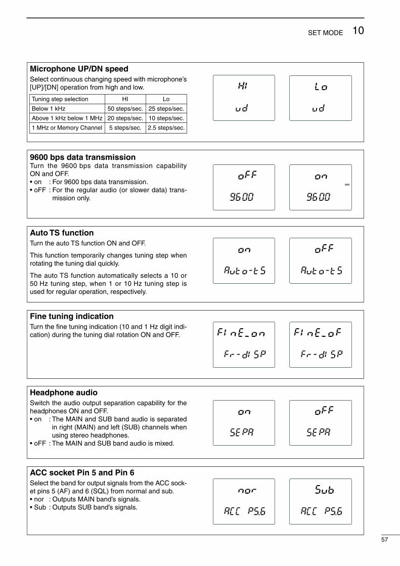
57
10SET MODE
Microphone UP/DN speedSelect continuous changing speed with microphone’s [UP]/[DN] operation from high and low.
Headphone audioSwitch the audio output separation capability for the headphones ON and OFF.•on :TheMAINandSUBbandaudioisseparated
in right (MAIN) and left (SUB) channels when using stereo headphones.
•oFF :TheMAINandSUBbandaudioismixed.
Fine tuning indicationTurn the fine tuning indication (10 and 1 Hz digit indi-cation) during the tuning dial rotation ON and OFF.
Auto TS functionTurn the auto TS function ON and OFF.
This function temporarily changes tuning step when rotating the tuning dial quickly.
The auto TS function automatically selects a 10 or 50 Hz tuning step, when 1 or 10 Hz tuning step is used for regular operation, respectively.
9600 bps data transmissionTurn the 9600 bps data transmission capability ON and OFF.•on :For9600bpsdatatransmission.•oFF :Fortheregularaudio(orslowerdata)trans-
mission only.
9600
Tuning step selection HI Lo
Below 1 kHz 50 steps/sec. 25 steps/sec.
Above 1 kHz below 1 MHz 20 steps/sec. 10 steps/sec.
1 MHz or Memory Channel 5 steps/sec. 2.5 steps/sec.
ACC socket Pin 5 and Pin 6Select the band for output signals from the ACC sock-et pins 5 (AF) and 6 (SQL) from normal and sub.•nor :OutputsMAINband’ssignals.•Sub :OutputsSUBband’ssignals.

58
10 SET MODE
ACC socket Pin 8Assign the ACC socket pin 8 action/connection from ALC and microphone up/down.•ALC:InputsALCsignal.•ud :Inputsup/downsignalsfromthemicrophone.
ACC socket Pin 4/DATA socket Pin 1Select modulation signal input level from high and low.•HI:Highmodulationsignallevel(200mVrms)•Lo:Lowmodulationsignallevel(2mVrms)
ACC socket Pin 3 for 144 MHz bandSwitch the SEND signal output for 144 MHz band op-eration ON and OFF.
ACC socket Pin 3 for 430(440) MHz bandSwitch the SEND signal output for 430(440) MHz band operation ON and OFF.
ACC socket Pin 3 for 1200 MHz bandSwitch the SEND signal output for 1200 MHz band operation ON and OFF.
Preamplifier controller for 144 MHzSwitch the preamplifier control capability ON and OFF. When using the optional AG-25, ON must be se-lected. Otherwise, the preamplifier is never activated.
DO NOT connect any equipment, such as an SWR or power meter, between the transceiver and pre-amplifier. In such case, the preamplifier may not activate properly.
P.AMP P.AMP

59
10SET MODE
Preamplifier controller for 430(440) MHzSwitch the preamplifier control capability ON and OFF. When using the optional AG-35, ON must be se-lected. Otherwise, the preamplifier is never activated.
DO NOT connect any equipment, such as an SWR or power meter, between the transceiver and pre-amplifier. In such case, the preamplifier may not activate properly.
P.AMP P.AMP
Preamplifier controller for 1200 MHzSwitch the preamplifier control capability ON and OFF. When using the optional AG-1200, ON must be selected. Otherwise, the preamplifier is never activat-ed.
DO NOT connect any equipment, such as an SWR or power meter, between the transceiver and pre-amplifier. In such case, the preamplifier may not activate properly.
P.AMP P.AMP
CI-V addressTo distinguish between equipment, each CI-V trans-ceiver has its own Icom standard address in hexa-decimal code. The IC-910H’s address is 60H.
When 2 or more IC-910Hs are connected to an op-tional CT-17 ci-v level converter, select a different address for each IC-910H in the range 01H to 7FH.
CI-V baud rateSelect transfer rate for CI-V remote control from Auto, 300, 1200, 4800, 9600 and 19200 bps.
CI-V transceiveTransceive operation is possible with the IC-910H connected to other Icom transceivers or receivers.
When“on” isselected,changingtheoperatingfre-quency, operating mode, etc. on the IC-910H auto-matically changes those of connected transceivers (or receivers) and vice versa.

60
10 SET MODE
n FM set modeOffset frequency for 144 MHzSet the offset frequency for duplex (repeater) opera-tion within 0–10.00000 MHz range.This item is displayed when the 144 MHz band is ac-cessed, including the SUB band access capability.• Default value: 0.6000
FM
Offset frequency for 430(440) MHzSet the offset frequency for duplex (repeater) opera-tion within 0–10.00000 MHz range.This item is displayed when the 430(440) MHz band is accessed, including the SUB band access capa-bility.• Default value: 5.0000
FM
Offset frequency for 1200 MHzSet the offset frequency for duplex (repeater) opera-tion within 0–100.00000 MHz range.This item is displayed when the 1200 MHz band is accessed, including the SUB band access capability.• Default value: 20.0000
FM
Tone encoder frequency for 144 MHz (except Europe, Sweden and Italy versions)Select tone encoder frequency for accessing a repeat-er, etc. from one of 50 available tone frequencies.This item is displayed when the 144 MHz band is ac-cessed, including the SUB band access capability.• Default value: 88.5
FM
T
Tone encoder frequency for 430(440) MHz (except Europe, Sweden and Italy versions)Select tone encoder frequency for accessing a repeat-er, etc. from one of 50 available tone frequencies.This item is displayed when the 430(440) MHz band is accessed, including the SUB band access capability.• Default value: 88.5
FM
T
Tone encoder frequency for 1200 MHz (except Europe, Sweden and Italy versions)Select tone encoder frequency for accessing a repeat-er, etc. from one of 50 available tone frequencies.This item is displayed when the 1200 MHz band is accessed, including the SUB band access capability.• Default value: 88.5
FM
T

61
10SET MODE
Tone squelch frequency for 144 MHzSelect tone squelch frequency from one of 50 avail-able tone frequencies.This item is displayed when the 144 MHz band is ac-cessed, including the SUB band access capability.• Default value: 88.5
FM
-SQLT
Tone squelch frequency for 430(440) MHzSelect tone squelch frequency from one of 50 avail-able tone frequencies.This item is displayed when the 430(440) MHz band is accessed, including the SUB band access capa-bility.• Default value: 88.5
FM
-SQLT
Tone squelch frequency for 1200 MHzSelect tone squelch frequency from one of 50 avail-able tone frequencies.This item is displayed when the 1200 MHz band is accessed, including the SUB band access capability.• Default value: 88.5
FM
-SQLT
One-touch repeater shift direction (except Europe, Sweden and Italy versions)Select shift direction for one-touch repeater function from DUP– and DUP+.
DUP
FM
DUP
FM
Auto repeater function (U.S.A. and Korea versions)Turn the auto repeater function ON and OFF.To activate the auto repeater function, ON must be selected in this setting after programming the auto re-peater frequency range. (p. 34)
U.S.A. version:•“on1” Activatesduplexonly.•“on2” Activatesduplexandtone.•“oFF” AutorepeaterfunctionisturnedOFF.
Korea version:•“ON” Activatesduplexandtone.•“OFF” AutorepeaterfunctionisturnedOFF.
FM FM
FM center indicatorTurn the FM center indication ON and OFF.When the indication is turned ON and the received signal is off-center in FM mode, the receive indicator (green)flashes.
FM FM

62
10 SET MODE
n SSB/CW set modeSquelch threshold Select the squelch threshold level from 12 and 13 o’clock.•12 :Thesquelchclosesaroundthe12o’clockposi-
tion of the [SQL] control.•13 :Thesquelchclosesaroundthe13o’clockposi-
tion of the [SQL] control.
Carrier frequency Adjust the carrier frequency for SSB (USB/LSB) mode operation within –200 to +200 Hz range in 10 Hz steps.
LSBUSB LSBUSB
CW pitch frequency Adjust the CW pitch frequency within 300 to 900 Hz range in 10 Hz steps.
CW
CW keying speed adjustmentAdjust the built-in electric keyer keying speed to the desired level within 6 to 60 WPM range.
CW CW
Semi break-inTurn the semi break-in function ON and OFF.
CW CW
CW break-in delayAdjust the CW break-in delay time to the desired level within 2.0 to 13.0 sec. range in 0.1 sec. steps.
CW CW

63
10SET MODE
AF control relationTurn the relation of [AF] control for CW side tone out-put level ON and OFF.•on :CWsidetoneoutput level isadjustablevia
[AF] control adjustment.•oFF :CWsidetoneoutputlevelisfixedregardless
of [AF] control setting.
CW CW
CW side tone output levelAdjust the CW side tone output to the desired level within 0 (no output) to 100 (maximum output) range.
CW CW
Key typeSelect the key type from normal, reverse, bug, OFF and microphone [UP]/[DN].•n :Usebuilt-inelectronickeyer.•r :Usebuilt-inelectronickeyerwithreversedpo-
larity.•buG:Usebuilt-inelectronickeyerasbugkey.•oFF :Useexternalelectronickeyerorstraightkey.•ud :Usemicrophone’s[UP]/[DN]asapaddle.
CW CW
CW dot-dash ratioAdjust the CW dot-dash ratio to the desired level with-in1:1:2.8to1:1:4.5range.
CW
C/N type for 1200 MHzSelect the C/N type for the 1200 MHz band operation from type 1 and 2.•tyPE1 :Providesbettercharacteristicsfornear-
by interference in FM mode operation. •tyPE2 :Provideslowernoiselevel justaround
the signal in SSB/CW mode operation.This item is displayed only when the optional UX-910 is installed.
USBLSBCW FM

64
10 SET MODE
n Scan set mode
n Memo pad set mode
Programmed scanning range Select the programmed scan range from 1A-1b, 2A-2b and 3A-3b.•1A-1b :Scanswithintherangeprogrammedin
the memory channel 1A and 1b.•2A-2b :Scanswithintherangeprogrammedin
the memory channel 2A and 2b.•3A-3b :Scanswithintherangeprogrammedin
the memory channel 3A and 3b.
SCANSCAN
Scan resume conditionSelect the scan resume condition from ON and OFF.•on :Scanresumes.•oFF :Scancancelswhenasignalisreceived.
SCAN SCAN
Number of memo pad channelsSelect the number of memo pad channels available from 5 and 10.•5 :5memopadchannelscanbeused.•10:10memopadchannelscanbeused.
n Compressor set modeCompression levelAdjust the compression level for the speech compres-sor to the desired level within 0–100% range. COMP
Scanning speedSelect the scanning speed from high and low.
SCAN SCAN
Scan type HI Lo
Memory scan (Mode select) 20 CH/sec. 10 CH/sec.
Prog. scan (TS<1 kHz) 50 steps/sec. 25 steps/sec.
Prog. scan (TS>1 kHz) 20 steps/sec. 10 steps/sec.
Tone scan 20 steps/sec. 10 steps/sec.

65
10SET MODE
n VOX set modeVOX sensitivityAdjust the VOX sensitivity within 0–100% range.
VOX
VOX delay timeAdjust the transmit-to-receive switching delay to the desired level within 0.0 sec. to 2.0 sec. range in 0.1 sec. steps.
VOX
n Attenuator set modeAttenuation level for 144 MHzAdjust the attenuation level to the desired level within 0–100% range for the 144 MHz band operation.
Attenuation level for 430(440) MHzAdjust the attenuation level to the desired level within 0–100% range for the 430(440) MHz band operation.
Anti VOX Adjust the anti VOX gain within 0–100% range.
VOX

66
10 SET MODE
n Transmit set modeTime-out timerSelect the time period for the time-out timer function from OFF, 3, 5, 10, 20 and 30 min.
PTT lockTurn the transmission inhibit capability ON and OFF.Any control for transmission is inhibited when this item is ON.
SUB band muteTurn the SUB band audio mute function ON and OFF.The SUB band audio is muted while transmitting when this function is turned ON.
SUB SUB

Noise reduction level for 1200 MHz Adjust the noise reduction level to the desired level within 0–15 for the 1200 MHz band operation.Adjust it to the level that noise signals are reduced, and received audio has no distortion.
This item is displayed only when the optional UT-106 is installed.
NR
Sweeping intervalSelect the sweeping interval for the simple band scope function from 3, 5 and 10 sec. SWP
67
10SET MODE
n NR set modeNoise reduction level for 144 MHz Adjust the noise reduction level to the desired level within 0–15 for the 144 MHz band operation.Adjust it to the level that noise signals are reduced, and received audio has no distortion.
This item is displayed only when the optional UT-106 is installed.
NR
Noise reduction level for 430(440) MHz Adjust the noise reduction level to the desired level within 0–15 for the 430(440) MHz band operation.Adjust it to the level that noise signals are reduced, and received audio has no distortion.
This item is displayed only when the optional UT-106 is installed.
NR
n SWP set mode

n RIT/SHIFT set mode
68
10 SET MODE
RIT control assignmentAssign [RIT] control function from rit, dIAL, SubdIAL and Sub-SFt.•rit :[RIT]controlfunctionsasRITcontrol.•dIAL :[RIT]controlfunctionsastuningdialfor
MAIN band.•SubdIAL :[RIT]controlfunctionsastuningdialfor
SUB band.•Sub-SFt :[RIT]controlfunctionsasIFshiftcontrol
for SUB band.
SHIFT control assignmentAssign [SHIFT] control function from SFt, Sub-SFt, dIAL and SubdIAL.•SFt :[SHIFT]controlfunctionsasIFshiftcon-
trol.•Sub-SFt :[SHIFT]controlfunctionsasIFshiftcon-
trol for SUB band.•dIAL :[SHIFT]controlfunctionsastuningdial
for MAIN band.•SubdIAL :[SHIFT]controlfunctionsastuningdial
for SUB band.
RIT indicationTurn the RIT adjusting value indication ON and OFF.The value is displayed while adjusting when this func-tion is turned ON.

69
10SET MODE
n Speech set modeOutput levelAdjust the speech audio output level within 0 (no out-put) to 100 (maximum output) range.•Defaultvalue:50
Announcement languageSelect the announcement language from English, Japanese and OFF.•EnG:AnnouncesinEnglish.•JPn :AnnouncesinJapanese•oFF :Noannouncement.
Announcement speedSelect the announcement speed from high and low.•HI :Fasterannouncement.•Lo :Slowerannouncement.
S-meter level announcementTurn the S-meter level announcement capability ON and OFF.•on :AnnouncesS-meterlevelwiththeoperating
frequency.•oFF :Announcestheoperatingfrequencyonly.

11
70
OPTION INSTALLATIONS
Circuitly fuse(FGB 4 A)
Cooling fan
J1801for UT-102 connection
SSB filter(MAIN band)
CW-N filter(MAIN band)
CW-N filter(SUB band)
SSB filter(SUB band)
MAIN unit
PLL unit
DSP unit
PLL ref. signal(for UX-910)
DSP unit
DC powerconnector
n Internal view• Top view — PA unit
• Bottom view — PLL/MAIN unit

Follow the case and cover opening procedures shown here when you want to install an optional unit or adjust the internal units, etc.
q Remove the 5 screws from the top of the trans-ceiver and the 4 screws from the sides, then lift up the top cover.
w Turn the transceiver upside down.e Remove the 5 screws from the bottom of the
transceiver, then lift up the bottom cover.
CAUTION: DISCONNECT the DC power cable from the transceiver before performing any work on the transceiver. Otherwise, there is a danger of electric shock and/or equipment damage.
Disconnect the speaker cable.
71
11OPTION INSTALLATIONS
n Opening the transceiver’s case
The UT-102 announces the accessed readout’s fre-quency, mode, etc. (S-meter level can also be an-nounced—p. 69) in a clear, electronically-generated voice, in English (or Japanese).➥ Push [SPCH] to announce the frequency, etc.
q Remove the bottom cover as shown above. •RemovetheUX-910ifyouhaveinstalledit.(p.73)w Remove the protective paper attached to the bot-
tom of the UT-102 to expose the adhesive strip.e Plug UT-102 into J1801 on the MAIN unit as shown
in the diagram at right.r Return the bottom cover to its original position.t Set the speech level, announcement language and
S-meter announcement in the speech set mode (p. 69) if desired.
UT-102
MAIN unit
J1801
n UT-102 VOICE SYNTHESIZER UNIT
D Opening the PA unit coverq Remove the 8 screws and grounding plate from the
PA unit cover.w Remove fastening tape from the inside power
cable.
grounding plate
e Slide the PA unit cover as shown below.
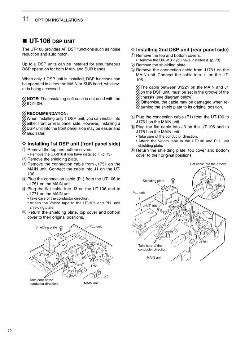
72
11 OPTION INSTALLATIONS
The UT-106 provides AF DSP functions such as noise reduction and auto notch.
Up to 2 DSP units can be installed for simultaneous DSP operation for both MAIN and SUB bands.
When only 1 DSP unit is installed, DSP functions can be operated in either the MAIN or SUB band, whichev-er is being accessed.
NOTE: The insulating soft case is not used with the IC-910H.
RECOMMENDATION: When installing only 1 DSP unit, you can install into either front or rear panel side. However, installing a DSP unit into the front panel side may be easier and also safer.
D Installing 1st DSP unit (front panel side)q Remove the top and bottom covers. •RemovetheUX-910ifyouhaveinstalledit.(p.73)w Remove the shielding plate.e Remove the connection cable from J1751 on the
MAIN unit. Connect the cable into J1 on the UT-106.
r Plug the connection cable (P1) from the UT-106 to J1751 on the MAIN unit.
tPlug theflatcable intoJ3on theUT-106and toJ1771 on the MAIN unit.
•Takecareoftheconductordirection. •Attach theVelcro tape to the UT-106 and PLL unit
shielding plate.y Return the shielding plate, top cover and bottom
cover to their original positions.
Take care of the conductor direction.
J1771
J3 J1
J1751
Shielding plate
UT-106
MAIN unit
P1
PLL unit
D Installing 2nd DSP unit (rear panel side)q Remove the top and bottom covers. •RemovetheUX-910ifyouhaveinstalledit.(p.73)w Remove the shielding plate.e Remove the connection cable from J1761 on the
MAIN unit. Connect the cable into J1 on the UT-106.
The cable between J1221 on the MAIN and J1 on the DSP unit, must be set in the groove of the chassis (see diagram below). Otherwise, the cable may be damaged when re-turning the shield plate to its original position.
r Plug the connection cable (P1) from the UT-106 to J1761 on the MAIN unit.
tPlug theflatcable intoJ3on theUT-106and toJ1781 on the MAIN unit.
•Takecareoftheconductordirection. •Attach theVelcro tape to the UT-106 and PLL unit
shielding plate.y Return the shielding plate, top cover and bottom
cover to their original positions.
J1781
J1761
J3 J1
Shielding plate
UT-106
MAIN unit
PLL unit
Take care of the conductor direction.
P1
J1
Set cable into the groove.
n UT-106 DSP UNIT

73
11OPTION INSTALLATIONS
The UX-910 is a band unit for 1200 MHz band opera-tion. FM, SSB (USB/LSB), CW and CW narrow mode operations are available.
q Remove the bottom cover as shown in the diagram on p. 71.
w Remove the antenna plate from the chassis using a standard screw driver.
WARNING! NEVER attempt to remove the antenna plate using your finger, this may result in injury.
e Connect the FFC (Flexible Flat Cable) of the UX-910 to J2 on the MAIN unit, DC power cable to the power connector (W305) from the PA unit and the coaxial cable to the J541 on the PLL unit.
CAUTION NEVER catch the cables from the optional DSP unit(s) between chassis and the UX-910, this may damage the DSP unit(s) and/or transceiver.
J541
J2
UX-910
PLL unit
Power connector
DC power cable
Coaxial cable
Flexible flat cable
r Place the UX-910 using the supplied 4 screws.
BE CAREFUL not to drop the supplied screws inside the transceiver.
Antenna plate
UX-910
Turn the flexible flat cable up under the UX-910.
J2MAIN unit
Flexible flat cable
UX-910
t Return the bottom cover to its original position.
n UX-910 1200 MHz BAND UNIT
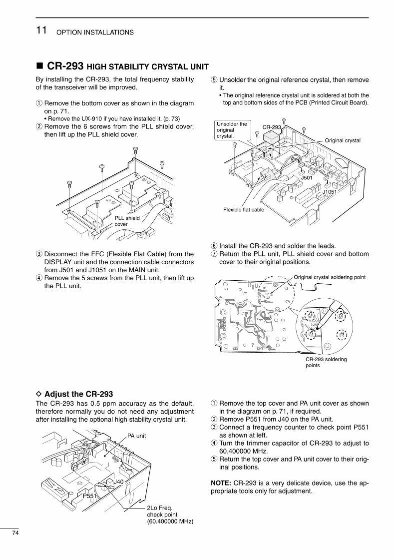
D Adjust the CR-293The CR-293 has 0.5 ppm accuracy as the default, therefore normally you do not need any adjustment after installing the optional high stability crystal unit.
q Remove the top cover and PA unit cover as shown in the diagram on p. 71, if required.
w Remove P551 from J40 on the PA unit.e Connect a frequency counter to check point P551
as shown at left.r Turn the trimmer capacitor of CR-293 to adjust to
60.400000 MHz.t Return the top cover and PA unit cover to their orig-
inal positions.
NOTE: CR-293 is a very delicate device, use the ap-propriate tools only for adjustment.
74
11 OPTION INSTALLATIONS
By installing the CR-293, the total frequency stability of the transceiver will be improved.
q Remove the bottom cover as shown in the diagram on p. 71.
•RemovetheUX-910ifyouhaveinstalledit.(p.73)w Remove the 6 screws from the PLL shield cover,
then lift up the PLL shield cover.
PLL shieldcover
e Disconnect the FFC (Flexible Flat Cable) from the DISPLAY unit and the connection cable connectors from J501 and J1051 on the MAIN unit.
r Remove the 5 screws from the PLL unit, then lift up the PLL unit.
t Unsolder the original reference crystal, then remove it.
•The original reference crystal unit is soldered at both the top and bottom sides of the PCB (Printed Circuit Board).
J501
Original crystal
CR-293
J1051
Flexible flat cable
Unsolder the original crystal.
y Install the CR-293 and solder the leads.u Return the PLL unit, PLL shield cover and bottom
cover to their original positions.
CR-293 soldering points
Original crystal soldering point
n CR-293 HIGH STABILITY CRYSTAL UNIT
J40
P551
2Lo Freq. check point(60.400000 MHz)
PA unit

75
11OPTION INSTALLATIONS
The IC-910H has a CW narrow mode to provide better S/N (Signal-to-Noise), or to reject interference. To op-erate the CW narrow mode, an optional CW narrow fil-ter is necessary.
NOTE: For CW narrow mode during satellite opera-tion, the FL-133 (for SUB band filter) is necessary since the SUB band circuit is used for receiving, al-though the MAIN band display shows receive fre-quency.
q Remove the bottom cover as shown in the diagram on p. 71.
•RemovetheUX-910ifyouhaveinstalledit.(p.73) •Disconnectthecablesandflatcableswhenyouhavein-
stalled the UT-106. (p. 73)w Disconnect the connection cable connectors from
J51, J501, J651 and J1051 on the MAIN unit.e Remove the 2 clips and the 6 screws from the MAIN
unit.
WARNING! BE CAREFUL not to pinch your finger with the clip.
Clips
J51
J651
Red Gray
J501
J1051
MAIN unit
PLL unit
rDisconnecttheflatcableconnectorsfromJ1101,J1301 and J1351 on the MAIN unit, then lift up the MAIN unit as below.
J1351
J1301J1101
Main unit
Slide the MAIN unit to the front panel side, then lift it up as the arrow.
Flat canbles
t Install FL-132 or FL-133 to the specified position on the MAIN unit.
FL-132(MAIN)
FL-133(SUB)
y Solder then cut the leads, keeping 2–3 mm (1⁄8″) of the leads from the bottom of the MAIN unit.
(MAIN)
(SUB)
u Return the MAIN unit and clips to their original posi-tions.
i Re-connect the connection cable connector to J51, J501, J651 and J1051 on the MAIN unit.
o Re-connect the flat cable connector to J1101, J1301 and J1351 on the MAIN unit.
•ReturntheUX-910ifyouhaveremovedit.(p.73) •Re-connectthecablesandflatcablesforUT-106when
you have disconnected them. (p. 73)!0 Return the bottom cover to the original position.
n FL-132/FL-133 CW NARROW FILTER
FILTER
Passband width at –6 dB at –60 dB
Built-in filter 2.3 kHz 4.2 kHz
FL-132/133 500 Hz 1.34 kHz

PO
WE
RR
EC
EIV
ET
RA
NS
MIT
SC
AN
DISP
LAY
PROBLEM POSSIBLE CAUSE SOLUTION REF.
SP
EE
CH
11
76
MAINTENANCE
n TroubleshootingThe following chart is designed to help you correct problems which are not equipment malfunctions.
If you are unable to locate the cause of a problem or solve it through the use of this chart, contact your nearest Icom Dealer or Service Center.
Power does not come on when [POWER] is pushed.
No sounds comes from the speaker.
Sensitivity is low.
Received audio is distort-ed.
Transmitting is impossible.
Output power is too low.
No contact possible with another station.
Transmitted signals are distorted.
Repeater cannot be ac-cessed.
Programmed scan does not start.
Memory scan does not start.
Mode select scan does not start.
No announcement when [SPCH] is pushed.
The displayed frequency does not change properly.
•DCpowercableisimproperlyconnected.•Fuseisblown.
•Volumelevelistoolow.
•Thesquelchisclosed.
•Thetransceiverisinthetransmittingcondition.
•Theantennaisnotconnectedproperly.•Theattenuatorisactivated.•TheS-metersquelchisactivated.
•Incorrectsideband(USB/LSB)isselected.
•ReceivinganFMsignal.•Noiseblankerisactivated.
•Noisereductionisactivated.
•PTTlockfunctionisactivated.
•[RFPWR]issettoofarcounterclockwise.•[MICGAIN]issettoofarcounterclockwise.
•Splitfrequencyoperationorduplexoperationisactivated.
•RITfunctionisactivated.
•[MICGAIN]tofarclockwise.
•Duplexoperationisnotactivated.
•Nosubaudibletoneorincorrecttonefrequen-cy is selected.
•VFOmodeisnotselected.•[RF/SQL]isassignedtoRFgainandsquelchis opened.
•Memorymodeisnotselected.•Nomemorychannelsareprogrammed.
•Modeselectscanmodehasnotbeenselected.
•Onlyonechannelisprogrammedwiththese-lected operating mode.
•The voice synthesizer unit has not been in-stalled.
•Theannouncementlevelissetto“0”ortoolow.
•Theannouncementlanguageissetto“oFF.”
•Thediallockfunctionisactivated.•TheinternalCPUhasmalfunctioned.
•ReconnecttheDCpowercablecorrectly.•Checkthecause, thenreplacethefusewitha
spare one. (Fuses are installed in the DC power cable and the internal PA unit.)
•Rotate[AF]clockwisetoobtainasuitablelisten-ing level.
•Rotate[RF/SQL]to12o’clockpositiontoopenthe squelch.
•Push[TRANSMIT]toreceiveorchecktheSENDline of an external unit, if desired.
•Reconnecttotheantennaconnector.•Push[ATT]toturntheattenuatorOFF.•Rotate[RF/SQL]tothepositionwherethenoise
just disappears.
•SwitchUSBandLSBbypushing[SSB/CW]for1 sec.
•Push[FM]toselectFMmode.•Push[AFC/NB]toturnthenoiseblanker func-
tion OFF.•SetthenoisereductionlevelintheNRsetmode
for maximum readability using [SET] and [AFC/NB•NR], or turnOFF the functionbypushing[AFC/NB•NR]for1sec.
•TurnthePTTlockfunctionOFFintheTRANSMITset mode using [SET] and [TRANSMIT].
•Rotate[RFPWR]clockwise.•Rotate[MICGAIN]clockwise.
•Push[SPLIT]momentarilyorfor1sec.toturnthesplit or duplex function OFF.
•Push[RIT]toturntheRITfunctionOFF.
•Set[MICGAIN]toasuitablelevel.
•Push[SPLIT•DUP]for1sec.toturnduplexop-eration ON.
•Push[TONE]toactivatethesubaudibletoneorselect a suitable tone frequency in the FM set mode using [SET] and [FM].
•Push[V/M1]toselectVFOmode.•Reset[RF/SQL]controlassignmentandsetitto
the threshold point.
•Push[V/M1]toselectmemorymode.•Programdesiredfrequenciesintomemorychan-
nels.
•Push[SPCH•LOCK]for1sec.onthedesiredop-erating mode programmed channel.
•Programmore than twochannelswith thede-sired operating mode.
•Installtheoptionalvicesynthesizerunit,UT-102.
•Settheannouncementleveltoasuitablelevelinthe SPCH set mode using [SET] and [SPCH].
•Settheannouncementlanguageto“Eng”(orJPn)in the SPCH set mode using [SET] and [SPCH].
•Push[SPCH•LOCK]toturnthelockfunctionOFF.•ResettheCPU.
–p. 77
p. 26
p. 26
pgs. 2, 13
–p. 29p. 26
p. 23
p. 23p. 30
p. 31
p. 66
p. 32p. 32
p. 37
p. 27
p. 32
p. 34
p. 35
p. 21p. 26
p. 40p. 41
p. 47
p. 41
p. 71
p. 69
p. 69
p. 25p. 77

77
11MAINTENANCE
n Fuse replacementIf a fuse blows or the transceiver stops functioning, try to find the source of the problem, and replace the damaged fuse with a new, rated fuse.
CAUTION: DISCONNECT the DC power cable from the transceiver when changing a fuse.
The IC-910H has 2 types of fuses installed for trans-ceiver protection.•DCpowercablefuses �������� FGB 30 A•Circuitryfuse ������������ FGB 4 A
DC POWER CABLE FUSE REPLACEMENT
30 A fuse
CIRCUITRY FUSE REPLACEMENTThe 13.8 V DC from the DC power cable is applied to all units in the IC-910H, except for the power amplifi-er, through the circuitry fuse. This fuse is installed in the PA unit.
q Remove the top cover as shown on p. 71.w Remove the 11 screws from the PA shielding plate,
then remove the plate.e Replace the circuitry fuse as shown in the diagram
at right.r Replace the PA shielding plate and top cover. Circuitry fuse (4 A)
n CPU resetting Resetting CLEARS all programmed contents in memory channels and returns programmed values in set mode to default values.
When first applying power or when the function seems to be displaying erroneous information, reset theCPUasfollows:
q Make sure the transceiver power is OFF.w While pushing [MW 4] and [M-CL 5], push
[POWER] to turn power ON. •TheinternalCPUisreset. •The transceiverdisplays its initialVFO frequencies
when resetting is complete.
[POWER] [MW 4] [M-CL 5]

CONTROLLER TO IC-910H
FE
FE
FE 60 E0 Cn Sc Data area FD
Pre
ambl
e co
de (
fixed
)
Tran
scei
ver’s
def
ault
addr
ess
Con
trol
ler’s
def
ault
addr
ess
Com
man
d nu
mbe
r(s
ee ta
ble
at r
ight
)S
ub c
omm
and
num
ber
(see
tabl
e at
rig
ht)
BC
D c
ode
data
for
freq
uenc
y or
mem
ory
num
ber
entr
y
End
of m
essa
ge c
ode
(fix
ed)
OK MESSAGE TO CONTROLLER
FE FE E0 60 FB FD
Pre
ambl
e co
de (
fixed
)
Con
trol
ler’s
def
ault
addr
ess
Tran
scei
ver’s
def
ault
addr
ess
OK
cod
e (f
ixed
)
End
of m
essa
ge c
ode
(fix
ed)
NG MESSAGE TO CONTROLLER
FE FE E0 60 FA FD
Pre
ambl
e co
de (
fixed
)
Con
trol
ler’s
def
ault
addr
ess
Tran
scei
ver’s
def
ault
addr
ess
NG
cod
e (f
ixed
)
End
of m
essa
ge c
ode
(fix
ed)
IC-910H TO CONTROLLER
FE E0 60 Cn Sc Data area FD
Pre
ambl
e co
de (
fixed
)
Con
trol
ler’s
def
ault
addr
ess
Tran
scei
ver’s
def
ault
addr
ess
Com
man
d nu
mbe
r(s
ee ta
ble
at r
ight
)S
ub c
omm
and
num
ber
(see
tabl
e at
rig
ht)
BC
D c
ode
data
for
freq
uenc
y or
mem
ory
num
ber
entr
y
End
of m
essa
ge c
ode
(fix
ed)
q w e r t y u
q w e r t y u
13
78
CONTROL COMMAND
• CI-V connection exampleThe transceiver can be connected through an option-al CT-17 CI-V LEVEL CONVERTER to a personal computer equipped with an RS-232C port. The Icom Communi-cations Interface-V (CI-V) controls the following func-tions of the transceiver.
Up to 4 Icom CI-V transceivers or receivers can be connected to a personal computer equipped with an RS-232C port. See p. 59 for setting the CI-V condition using set mode.
• Data formatThe CI-V system can be operated using the following data formats. Data formats differ according to com-mand numbers. A data area or sub command is added for some commands.
n Remote jack (CI-V) information
9–15V DC
personalcomputer
ct-17
BC-25(optional)IC-910H
mini-plug cable

Command Sub command
00 —
01
Same as command 06
02 —
03 —
04 —
05 —
00
06 01
03 04
—
00 01 07 A0 B0 D0 D1
—
01–0106* 08
09 —
0A —
0B —
0C —
0D —
00
0E 01
D0 D3
00 01 0F 10 11 12
00 01 02 03 04 10 05 06 07 08 09 10 11
11
00 10, 20, 30
00
13
01 02
DescriptionSend frequency data for trans-ceive.
Send mode data for transceive.
Read band edge frequencies.
Read operating frequency data.
Read operating mode data.
Set operating frequency.
Set LSB.Set USB.Set CW.Set FM.
Select VFO mode.
Select VFO A.Select VFO B.Equalize VFO A and VFO B.Switch VFO A and VFO B.Select MAIN VFO.Select SUB VFO.
Select memory mode.
Select memory channel.* 1A=0100 1b=0101 2A=0102 2b=0103 3A=0104 3b=0105 Call=0106
Memory write.
Transfer memory contents to VFO.
Memory clear.
Read duplex offset frequency.
Set duplex offset frequency.
Cancel scan.Start scan.Set scan resume OFF.Set scan resume ON.
Turn the split function OFF.Turn the split function ON.Set simplex operation.Set DUP– operation.Set DUP+ operation.
Set 1 Hz tuning step.Set 10 Hz tuning step.Set 50 Hz tuning step.Set 100 Hz tuning step.Set 1 kHz tuning step.Set 5 kHz tuning step.Set 6.25 kHz tuning step.Set 10 kHz tuning step.Set 12.5 kHz tuning step.Set 20 kHz tuning step.Set 25 kHz tuning step.Set 100 kHz tuning step.
Turn attenuator OFF.Turn attenuator ON.
Announce all S-meter levels, dis-played frequency and mode.Announce displayed frequency.Announce operating mode.
79
13CONTROL COMMAND
Command Sub command 01
02
03
04
06
14 09
0A
0B
0C
0E
0F
01 15 02
02 12 22 40 +level data 41
16 42
43 44
46 47 4A
19 00
00 01 02 +level data 03 +level data 04 1A +level data 05 +level data 06 07 08
09
00
1B
01
1C
00
Description[AF] level setting (0=max. CCW; 128=center; 255=max. CW).[RF GAIN] level setting (0=max. CCW; 255=max. CW).[SQL] level setting (0=max. CCW; 255=max. CW).[IF SHIFT] level setting (0=max. CCW; 128=center; 255=max. CW).Set noise reduction level (0=0%; 255=100%).Set CW pitch (0=300 Hz; 255=900 Hz).[RF PWR] level setting (0=max. CCW; 128=center; 255=max. CW).[MIC GAIN] level setting (0=max. CCW; 128=center; 255=max. CW).Key speed setting (0=6 wpm; 255=60 wpm).Set mic. compressor level (0=0%; 255=100%).Set break-in delay (0=2.0 sec; 255=13.0 sec.).
Read squelch condition (open or closed).Read S-meter level.
Set pre-amp (0=OFF; 1=ON).Set AGC (0=Slow; 1=Fast).Set noise blanker (0=OFF; 1=ON).Set noise reduction level (0=OFF; 1–15=ON).Set auto notch filter (0=OFF; 1=ON).Set subaudible tone (0=OFF; 1=ON).Set tone squelch (0=OFF; 1=ON).Set mic. compressor (0=OFF; 1=ON).Set VOX (0=OFF; 1=ON).Set break-in (0=OFF; 1=ON).Set AFC (0=OFF; 1=ON).
Read the transceiver ID.
Read/write memory channel.Set satellite memory.Set VOX gain level (0=0%; 255=100%).Set VOX delay (0=0 sec.; 20=2.0 sec.).Set anti-VOX (0=0%; 255=100%).Attenuation level setting (0=0%; 255=100%).Set RIT (0=OFF; 1=ON; 2=Sub dial).Set satellite mode (0=OFF; 1=ON).Set simple bandscope (0=OFF; 1=ON).Set sub band (0=OFF; 1=ON)
Set subaudible tone frequency (67 Hz=000670 to 254.1 Hz=002541)Set tone squelch frequency (67 Hz=000670 to 254.1 Hz=002541)
Set/read transceiver’s condition (0=Rx; 1=Tx)

• General•Frequencycoverage : (Unit:MHz)
*1 Optional UX-910*2 Guaranteed range is 144.0–148.0 MHz.*3 Guaranteed range is 430.0–450.0 MHz.*4 Guaranteed range is 1240.0–1300.0 MHz.•Mode :USB,LSB,CW,FM,FM-N*
*Not available in 1200 MHz•No.ofmemoryCh. :212(99 regular, 6 scan edges,
1 calls for each band) plus 10 satellite memories)
•Antennaconnector :SO-239(50 Ω; VHF) Type-N (50 Ω; UHF)
•Usabletemp.range :–10˚Cto+60˚C; +14˚Fto+140˚F
•Frequencystability :Lessthan±3ppm (–10to60˚C;+14to+140˚F)
•Frequencyresolution :1Hzminimum•Powersupply :13.8VDC±15%
(negative ground)•Currentdrain(at 13.8 V DC; approx.): Transmit Max. power 23.0 A Receive Standby 2.0 A (3.0 A; UX-910)
Max. audio 2.5 A (3.5 A; UX-910)•Dimensions :241(W) × 94(H) × 239(D) mm(projections not included) 91⁄2(W) × 311⁄16(H) × 913⁄32(D) in
•Weight(approx.) :4.5kg;10lb (5.35 kg; 11 lb 13 oz w/UX-910)
•ACC1connector :8-pinDINconnector•CI-Vconnector :2-conductor3.5(d)mm(1⁄8″)•DATAconnectors :6-pinminiDIN× 2
(for MAIN and SUB)
• Transmitter•Outputpower(continuously adjustable): 144 MHz 5–100 W 430(440) MHz 5–75 W 1200 MHz 1–10 W (optional UX-910)•Modulationsystem : SSB Balanced modulation FM Variable reactance modulation•Spuriousemission : 144/430(440) MHz More than 60 dB 1200 MHz More than 50 dB
•Carriersuppression :Morethan40dB•Unwantedsideband :Morethan40dB
suppression•Microphone connector:8-pinconnector(600Ω)•KEYconnector :3-conductor3.5(d)mm(1⁄4″)
• Receiver•Receivesystem : VHF SSB, CW Single conversion superheterodyne FM Double conversion superheterodyne UHF SSB, CW Double conversion superheterodyne FM Triple conversion superheterodyne•Intermediatefrequencies: (Unit:MHz)
•Sensitivity : SSB, CW (10 dB S/N)Lessthan0.11µV FM (12 dB SINAD) Lessthan0.18µV•Squelchsensitivity(threshold): SSB,CW Lessthan1.0µV FM Lessthan0.18µV•Selectivity : SSB, CW More than 2.3 kHz/–6 dB
Less than 4.2 kHz/–60 dB* FM More than 15.0 kHz/–6 dB
Less than 30.0 kHz/–60 dB* FM-N More than 6.0 kHz/–6 dB
Less than 18.0 kHz/–36 dB CW-N More than 0.5 kHz/–6 dB
(w/FL-132 or FL-133) Less than 1.34 kHz/–60 dB* *Except 1200 MHz band
•Spuriousandimagerejectionratio: 144/430(440) MHz More than 60 dB 1200 MHz More than 50 dB
•AFoutputpower :Morethan2.0Wat10%(at 13.8 V DC) distortion with an 8 Ω load
•RITvariablerange : 144/430(440)MHz ±1.0kHz(SSB, CW)
±5.0kHz(FM) 1200MHz ±2.0kHz(SSB, CW)
±10.0kHz(FM)•IF SHIFT variable range:Morethan±1.2kHz•PHONESconnector :3-conductor6.35(d)mm(1⁄4″)•Ext.SPconnectors :2-conductor3.5(d)mm(1⁄8″)
/8 Ω × 2 (for MAIN and SUB)
14
80
SPECIFICATIONS
All stated specifications are typical and subject to change without notice or obligation.
Version 144 MHz 430(440) MHz 1200 MHz*1
U.S.A. Tx:144.0–148.0 Tx:430.0–450.0 Tx:1240.0–1300.0
Rx:136.0–174.0*2 Rx:420.0–480.0*3 Rx:1240.0–1320.0*4
Europe 144.0–146.0 430.0–440.0 1240.0–1300.0
Australia 144.0–148.0 430.0–450.0 1240.0–1300.0
Sweden 144.0–146.0 432.0–438.0 1240.0–1300.0
Italy 144.0–146.0 430.0–434.0 1240.0–1245.0
435.0–438.0 1270.0–1298.0
MAIN BAND SUB BAND
1st 2nd 3rd 1st 2nd 3rd
SSB 10.8500 — — 10.9500 — —
CW 10.8491 — — 10.9491 — —
FM 10.8500 0.455 — 10.9500 0.455 —
SSB 71.2500 10.8500 — 71.3500 10.9500 —
CW 71.2491 10.8491 — 71.3491 10.9491 —
FM 71.2500 10.8500 0.455 71.3500 10.9500 0.455
SSB 243.8500 10.8500 — 243.9500 10.9500 —
CW 243.8491 10.8491 — 243.9491 10.9491 —
FM 243.8500 10.8500 0.455 243.9500 10.9500 0.45514
4 M
Hz
430(
440)
MHz
1200
MH
z
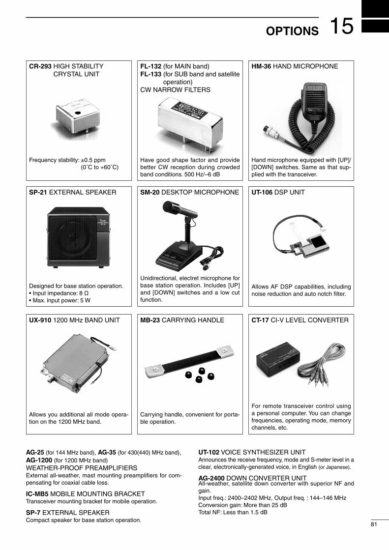
15
81
OPTIONS
SM-20 DESKTOP MICROPHONE
Unidirectional, electret microphone for base station operation. Includes [UP] and [DOWN] switches and a low cut function.
SP-21 EXTERNAL SPEAKER
Designed for base station operation.•Inputimpedance:8Ω•Max.inputpower:5W
CT-17 CI-V LEVEL CONVERTER
For remote transceiver control using a personal computer. You can change frequencies, operating mode, memory channels, etc.
HM-36 HAND MICROPHONE
Hand microphone equipped with [UP]/[DOWN] switches. Same as that sup-plied with the transceiver.
CR-293 HIGH STABILITY CRYSTAL UNIT
Frequencystability:±0.5ppm (0˚Cto+60˚C)
FL-132 (for MAIN band)FL-133 (for SUB band and satellite
operation)CW NARROW FILTERS
Have good shape factor and provide better CW reception during crowded band conditions. 500 Hz/–6 dB
MB-23 CARRYING HANDLE
Carrying handle, convenient for porta-ble operation.
UX-910 1200 MHz BAND UNIT
Allows you additional all mode opera-tion on the 1200 MHz band.
UT-106 DSP UNIT
Allows AF DSP capabilities, including noise reduction and auto notch filter.
AG-25 (for 144 MHz band), AG-35 (for 430(440) MHz band), AG-1200 (for 1200 MHz band)WEATHER-PROOF PREAMPLIFIERSExternal all-weather, mast mounting preamplifiers for com-pensating for coaxial cable loss.
IC-MB5 MOBILE MOUNTING BRACKETTransceiver mounting bracket for mobile operation.
SP-7 EXTERNAL SPEAKERCompact speaker for base station operation.
UT-102 VOICE SYNTHESIZER UNITAnnounces the receive frequency, mode and S-meter level in a clear, electronically-generated voice, in English (or Japanese).
AG-2400 DOWN CONVERTER UNITAll-weather, satellite down converter with superior NF and gain.Inputfreq.:2400–2402MHz,Outputfreq.:144–146MHzConversiongain:Morethan25dBTotalNF:Lessthan1.5dB
16
82
INSTALLATION NOTES
For amateur base station installations it is recommend-ed that the forwards clearance in front of the antenna array is calculated relative to the EIRP (Effective Iso-tropic Radiated Power). The clearance height below the antenna array can be determined in most cases from the RF power at the antenna input terminals.
As different exposure limits have been recommend-ed for different frequencies, a relative table shows a guideline for installation considerations.
Below 30 MHz, the recommended limits are speci-fied in terms of V/m or A/m fields as they are likely to fall within the near-field region. Similarly, the an-tennae may be physically short in terms of electrical length and that the installation will require some an-tenna matching device which can create local, high in-tensity magnetic fields. Analysis of such MF installa-tions is best considered in association with published guidance notes such as the FCC OET Bulletin 65 Edi-tion 97-01 and its annexes relative to amateur trans-mitter installations. The EC recommended limits are al-most identical to the FCC specified ‘uncontrolled’ limits and tables exist that show pre-calculated safe distanc-es for different antenna types for different frequency bands.Furtherinformationcanbefoundathttp://www.arrl.org/.
• Typical amateur radio installation
Exposure distance assumes that the predominant ra-diation pattern is forwards and that radiation vertical-ly downwards is at unity gain (sidelobe suppression is equal to main lobe gain). This is true of almost every gain antenna today. Exposed persons are assumed to be beneath the antenna array and have a typical height to 1.8 m.
The figures assume the worst case emission of con-stant carrier.
For the bands 10 MHz and higher the following power densitylimitshavebeenrecommended: 10–400 MHz 2 W/sq m 435 MHz 2.2 W/sq m 1296 MHz 6.5 W/sq m
EIRP Clearance heights by frequency band Watts 10–2 m 70 cm 23 cm 13 cm and above 1 2.1 m 2 m 2 m 2 m 10 2.8 m 2.7 m 2.5 m 2.3 m 25 3.4 m 3.3 m 2.7 m 2.5 m 100 5 m 4.7 m 3.6 m 3.2 m 1000 12 m 11.5 m 7.3 m 6.3 m
Forward clearance, EIRP by frequency band Watts 10–2 m 70 cm 23 cm 13 cm and above 100 2 m 2 m 1.1 m 0.7 m 1000 6.5 m 6 m 3.5 m 3 m 10,000 20 m 18 m 11 m 7 m 100,000 65 m 60 m 35 m 29 m
In all cases any possible risk depends on the trans-mitter being activated for long periods. (actual recom-mendation limits are specified as an average during 6 minutes) Normally the transmitter is not active for long periods of time. Some radio licenses will require that a timer circuit automatically cuts the transmitter after 1–2 minutes etc.
Similarly some types of transmitter, SSB, CW, AM etc. have a lower ‘average’ output power and the assessed risk is even lower.
VersionsoftheIC-910Hwhichdisplaythe“CE”symbol on the serial number seal, comply with the essential requirements of the European Radio and Telecommunication Terminal Direc-tive 1999/5/EC.
This warning symbol indicates that this equip-ment operates in non-harmonised frequency bands and/or may be subject to licensing condi-tions in the country of use. Be sure to check that you have the correct version of this radio or the correct programming of this radio, to com-ply with national licensing requirement.
• List of Country codes (ISO 3166-1) Country Codes
1 Austria AT 2 Belgium BE 3 Bulgaria BG 4 Croatia HR 5 Czech Republic CZ 6 Cyprus CY 7 Denmark DK 8 Estonia EE 9 Finland FI 10 France FR 11 Germany DE 12 Greece GR 13 Hungary HU 14 Iceland IS 15 Ireland IE 16 Italy IT 17 Latvia LV
Country Codes
18 Liechtenstein LI 19 Lithuania LT 20 Luxembourg LU 21 Malta MT 22 Netherlands NL 23 Norway NO 24 Poland PL 25 Portugal PT 26 Romania RO 27 Slovakia SK 28 Slovenia SI 29 Spain ES 30 Sweden SE 31 Switzerland CH 32 Turkey TR 33 United Kingdom GB

83
16INSTALLATION NOTES
DECLARATIONOF CONFORMITY
We Icom Inc. Japan1-1-32 Kamiminami, Hirano-ku, Osaka 547-0003 Japan
Kind of equipment: VHF/UHF ALL MODE TRANSCEIVER
This compliances is based on conformity according to Annex III of thedirective 1999/5/EC using the following harmonised standards:i) EN 301 489-1 v1.4.1 (2002-08)ii) EN 301 489-15 v1.2.1 (2002-08)iii) EN 301 783-2 v1.1.1 (2000-09)iv) EN 60950-1 (2001): A11: 2004v)
Type-designation: i910H
Signature
Authorized representative name
Place and date of issue
Icom (Europe) GmbHHimmelgeister straße 100D-40225 Düsseldorf
Düsseldorf 17th July 2007
H. IkegamiGeneral Manager
Version (where applicable):
Declare on our sole responsibility that this equipment complies the essential requirements of the Radio and Telecommunications Terminal Equipment Directive, 1999/5/CE, and that any applicable Essential Test Suite measurements have been performed.
Version and frequency coverage
* Optional UX-910
Version 144 MHz 430 MHz 1200 MHz*
Europe (#02) 144.0–146.0 430.0–440.0 1240.0–1300.0
Sweden (#05) 144.0–146.0 432.0–438.0 1240.0–1300.0
Italy (#08) 144.0–146.0430.0–434.0435.0–438.0
1240.0–1245.01270.0–1298.0
• About AG-25, AG-35 and AG-1200 preamplifiersThe use of IC-910H (#02, #05, #08) in combination with AG-25, AG-35 and/or AG-1200 preamplifiers do not comply with the European Harmon-ised Standard regulations. Please do not use the IC-910H with these pre-amplifiers (AG-25, AG-35 and/or AG-1200) intended for the US, Asian, Oceanian and African markets.

84
MEMO

85
MEMO

1-1-32 Kamiminami, Hirano-ku, Osaka 547-0003, Japan
IC-910H #05 (Sweden)
IC-910H #02 (Europe)
IC-910H #08 (Italy)
< Intended Country of Use >ATFIITPLGBRO
BEFRLVPTISTR
CYDELTSKLIHR
CZGRLUSINO
DKHUMTESCH
EEIENLSEBG
< Intended Country of Use >ATFIITPLGBRO
BEFRLVPTISTR
CYDELTSKLIHR
CZGRLUSINO
DKHUMTESCH
EEIENLSEBG
< Intended Country of Use >ATFIITPLGBRO
BEFRLVPTISTR
CYDELTSKLIHR
CZGRLUSINO
DKHUMTESCH
EEIENLSEBG
A-5699H-1EX-oaPrinted in Japan© 2000–2010 Icom Inc.
Printed on recycled paper with soy ink.