Instruction Manual PS 8000 2U Power Supply Series 8000-2U... · Bedienungsanleitung 3 PS 8000 2U...
52
EPS STROMVERSORGUNG PS 8032-20 2U: 09 230 130 PS 8360-15 2U: 09 230 137 PS 8065-10 2U: 09 230 131 PS 8360-30 2U: 09 230 138 PS 8160-05 2U: 09 230 132 PS 8720-15 2U: 09 230 139 PS 8080-40 2U: 09 230 133 PS 8040-60 2U: 09 230 144 PS 8080-60 2U: 09 230 134 PS 8040-120 2U: 09 230 145 PS 8080-120 2U: 09 230 135 PS 8160-60 2U: 09 230 136 Bedienungsanleitung Instruction Manual Abbildung zeigt Standardgerät 2 HE / Picture shows standard 2U version PS 8000 2U Laboratory Power Supply
Transcript of Instruction Manual PS 8000 2U Power Supply Series 8000-2U... · Bedienungsanleitung 3 PS 8000 2U...

EP
S S
TR
OM
VER
SO
RG
UN
G
PS 8032-20 2U: 09 230 130 PS 8360-15 2U: 09 230 137PS 8065-10 2U: 09 230 131 PS 8360-30 2U: 09 230 138PS 8160-05 2U: 09 230 132 PS 8720-15 2U: 09 230 139PS 8080-40 2U: 09 230 133 PS 8040-60 2U: 09 230 144PS 8080-60 2U: 09 230 134 PS 8040-120 2U: 09 230 145PS 8080-120 2U: 09 230 135PS 8160-60 2U: 09 230 136
BedienungsanleitungInstruction Manual
Abbildung zeigt Standardgerät 2 HE / Picture shows standard 2U version
PS 8000 2ULaboratory Power Supply

3BedienungsanleitungPS 8000 2U Serie
DE
Stand: 03.05.2016
Allgemeines
ImpressumEPS Stromversorgung GmbH
Alter Postweg 101
86159 Augsburg
Germany
Telefon: 0821 / 570451-0
Web: www.eps-germany.de
© EPS
Nachdruck, Vervielfältigung oder auszugsweise, zweck-entfremdete Verwendung dieser Bedienungsanleitung sind verboten und können bei Nichtbeachtung rechtliche Schritte nach sich ziehen.
Lebensgefahr!Gefährliche AusgangsspannungBei manchen Modelle kann die Ausgangsspannung be-rührungsgefährliche Werte von >60 VDC erreichen!Alle spannungsführenden Teile sind abzudecken. Alle Arbeiten an den Anschlussklemmen müssen im span-nungslosen Zustand des Gerätes erfolgen (Netzschalter ausgeschaltet) und dürfen nur von Personen durchge-führt werden, die mit den Gefahren des elektrischen Stroms vertraut sind oder unterrichtet wurden. Auch die Anschlüsse der an dem Gerät angeschlossenen Lasten oder Verbraucher sind berührungssicher auszuführen. Betriebsmittel, die an das Gerät angeschlossen werden, müssen so abgesichert sein, daß bei einer möglichen Überlast durch Fehlbedienung oder Fehlfunktion keine Gefahr von den angeschlossenen Betriebsmitteln aus-geht.
Achtung!Am DC-Ausgang kann nach dem Ausschalten des Aus-ganges oder des Gerätes für eine unbestimmte Zeit noch gefährlich hohe Spannung anliegen!
Unbedingt zu beachten:
• Das Gerät ist nur an der angegebenen Netzspannung zu betreiben
• Führen Sie keine mechanischen Teile, insbesondere aus Metall, durch die Lüftungsschlitze in das Gerät ein
• Vermeiden Sie die Verwendung von Flüssigkeiten aller Art in der Nähe des Gerätes, diese könnten in das Gerät gelangen
• Berühren Sie die Kontakte am Netzkabel oder der Netzan-schlußbuchse nie direkt nach dem Entfernen des Kabels aus der Steckdose, da die Gefahr eines Stromschlags besteht
• Schließen Sie Lasten, besonders niederohmige, nie bei eingeschaltetem Leistungsausgang an, es können Fun-ken und dadurch Verbrennungen an den Händen, sowie Beschädigungen am Gerät entstehen
• Um Schnittstellen in den dafür vorgesehenen Einschüben zu bestücken, müssen die einschlägigen ESD –Vorschriften beachtet werden.
• Nur im ausgeschalteten Zustand darf eine Schnittstellen-karte aus dem Einschub herausgenommen oder bestückt werden. Eine Öffnung des Gerätes ist nicht erforderlich.
• Alterung des Gerätes und sehr häufige Benutzung kann bei Bedienelementen (Taster, Drehknopf) dazu führen, daß diese nicht mehr wie erwartet reagieren.
• Keine externen Spannungsquellen mit umgekehrter Polari-tät am DC-Ausgang anschließen! Das Gerät wird dadurch zerstört.
• Möglichst keine externen Spannungsquellen am DC-Aus-gang anschließen, jedoch auf keinen Fall welche, die eine höhere Spannung erzeugen können als die Nennspannung des Gerätes!
4
DE
BedienungsanleitungPS 8000 2U SerieStand: 03.05.2016
Inhaltsverzeichnis
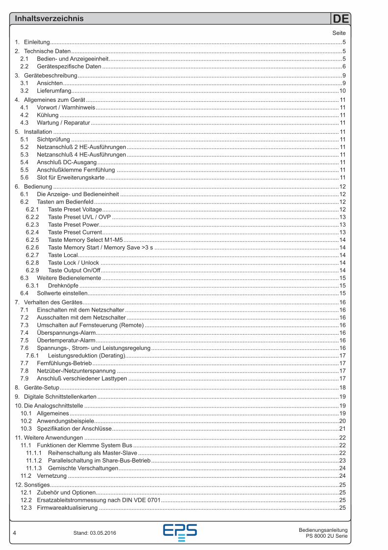
Seite1. Einleitung ...................................................................................................................................................................................52. Technische Daten ......................................................................................................................................................................5
2.1 Bedien- und Anzeigeeinheit ...............................................................................................................................................52.2 Gerätespezifische Daten ...................................................................................................................................................6
3. Gerätebeschreibung ..................................................................................................................................................................93.1 Ansichten ...........................................................................................................................................................................93.2 Lieferumfang....................................................................................................................................................................10
4. Allgemeines zum Gerät ........................................................................................................................................................... 114.1 Vorwort / Warnhinweis ..................................................................................................................................................... 114.2 Kühlung ........................................................................................................................................................................... 114.3 Wartung / Reparatur ........................................................................................................................................................ 11
5. Installation ............................................................................................................................................................................... 115.1 Sichtprüfung .................................................................................................................................................................... 115.2 Netzanschluß 2 HE-Ausführungen .................................................................................................................................. 115.3 Netzanschluß 4 HE-Ausführungen .................................................................................................................................. 115.4 Anschluß DC-Ausgang .................................................................................................................................................... 115.5 Anschlußklemme Fernfühlung ........................................................................................................................................ 115.6 Slot für Erweiterungskarte ............................................................................................................................................... 11
6. Bedienung ...............................................................................................................................................................................126.1 Die Anzeige- und Bedieneinheit ......................................................................................................................................126.2 Tasten am Bedienfeld ......................................................................................................................................................12
6.2.1 Taste Preset Voltage .................................................................................................................................................126.2.2 Taste Preset UVL / OVP ...........................................................................................................................................136.2.3 Taste Preset Power...................................................................................................................................................136.2.4 Taste Preset Current .................................................................................................................................................136.2.5 Taste Memory Select M1-M5 ....................................................................................................................................146.2.6 Taste Memory Start / Memory Save >3 s .................................................................................................................146.2.7 Taste Local................................................................................................................................................................146.2.8 Taste Lock / Unlock ..................................................................................................................................................146.2.9 Taste Output On/Off ..................................................................................................................................................14
6.3 Weitere Bedienelemente .................................................................................................................................................156.3.1 Drehknöpfe ...............................................................................................................................................................15
6.4 Sollwerte einstellen..........................................................................................................................................................157. Verhalten des Gerätes .............................................................................................................................................................16
7.1 Einschalten mit dem Netzschalter ...................................................................................................................................167.2 Ausschalten mit dem Netzschalter ..................................................................................................................................167.3 Umschalten auf Fernsteuerung (Remote) .......................................................................................................................167.4 Überspannungs-Alarm.....................................................................................................................................................167.5 Übertemperatur-Alarm .....................................................................................................................................................167.6 Spannungs-, Strom- und Leistungsregelung ...................................................................................................................16
7.6.1 Leistungsreduktion (Derating)...................................................................................................................................177.7 Fernfühlungs-Betrieb .......................................................................................................................................................177.8 Netzüber-/Netzunterspannung ........................................................................................................................................177.9 Anschluß verschiedener Lasttypen .................................................................................................................................17
8. Geräte-Setup ...........................................................................................................................................................................189. Digitale Schnittstellenkarten ....................................................................................................................................................1910. Die Analogschnittstelle ............................................................................................................................................................19
10.1 Allgemeines .....................................................................................................................................................................1910.2 Anwendungsbeispiele......................................................................................................................................................2010.3 Spezifikation der Anschlüsse ...........................................................................................................................................21
11. Weitere Anwendungen ............................................................................................................................................................2211.1 Funktionen der Klemme System Bus ..............................................................................................................................22
11.1.1 Reihenschaltung als Master-Slave ...........................................................................................................................2211.1.2 Parallelschaltung im Share-Bus-Betrieb ...................................................................................................................2311.1.3 Gemischte Verschaltungen .......................................................................................................................................24
11.2 Vernetzung ......................................................................................................................................................................2412. Sonstiges .................................................................................................................................................................................25
12.1 Zubehör und Optionen.....................................................................................................................................................2512.2 Ersatzableitstrommessung nach DIN VDE 0701 .............................................................................................................2512.3 Firmwareaktualisierung ...................................................................................................................................................25
5BedienungsanleitungPS 8000 2U Serie
DE
Stand: 03.05.2016
Über das Gerät
1. EinleitungDie Labornetzgeräte der Serie PS 8000 2U sind durch ihr 19“-Einschubgehäuse besonders für Prüfsysteme und Indu-striesteuerungen geeignet.
Über die gängigen Funktionen von Netzgeräten hinaus können 5 verschiedene Sollwertvorgabesätze eingestellt, gespeichert und bei Bedarf abgerufen werden. Weiterhin ist eine fest integrierte, analoge Schnittstelle, welche die gängigen Spannungsbereiche 0...5 V und 0...10 V bedient, vorhanden. Diese ermöglicht zum Einen die Überwachung des Gerätes und zum Anderen die komplette Fernsteuerung.
Mittels optionalen Schnittstellenkarten können von einem PC aus nahezu alle Funktionen des Gerätes gesteuert und über-wacht werden.
Geräte ab 1000 W Ausgangsleistung bieten mit einem „System Bus“ die Möglichkeit der Reihenschaltung im Master-Slave-Betrieb oder Parallelschaltung im Share-Bus-Betrieb, sowie eine einstellbare Leistungsbegrenzung (mit zwei Ausnahmen, siehe technische Daten).
Die Integration in bestehende Systeme ist mittels einer Schnitt-stellenkarte leicht möglich. Die Konfiguration ist einfach und wird am Gerät erledigt, sofern überhaupt nötig. Die Labornetzgeräte können so z. B. über die digitale Schnittstelle im Verbund mit anderen Labornetzgeräten betrieben werden bzw. von einer SPS oder einem anderem Gerät mit analoger Schnittstelle gesteuert werden oder dieses steuern.
Das Gerät ist mikroprozessorgesteuert, dies erlaubt eine ge-naue und schnelle Messung und Anzeige von Istwerten.
Die Hauptfunktionen im Überblick:
• Stellen von Strom und Spannung, jeweils 0...100%
• Einstellbarer Überspannungsschutz 0...110% Spannung
• Wechselbare Schnittstellenkarten (CAN, USB, RS232, IEEE/GPIB, Ethernet/LAN, Profibus)
• Analoge Schnittstelle für externe Ansteuerung und Messung mit 0...5 V oder 0...10 V (umschaltbar) für 0...100%
• Leistungsklassen 640 W, 1000 W, 1500 W und 3000 W
• Temperaturgesteuerte Lüfterregelung
• Zustandsanzeige (OT, OVP, CC, CV, CP)
• 5 speicherbare Sollwertsätze
• Master-Slave-Betrieb (Reihenschaltung) (Geräte ab 1 kW, außer 720 V-Modell)
• Share-Bus-Betrieb (Parallelschaltung) (Geräte ab 1 kW)
• Vector™ kompatibles CAN-System
• Kostenlose Windows-Software
• LabView™ VIs
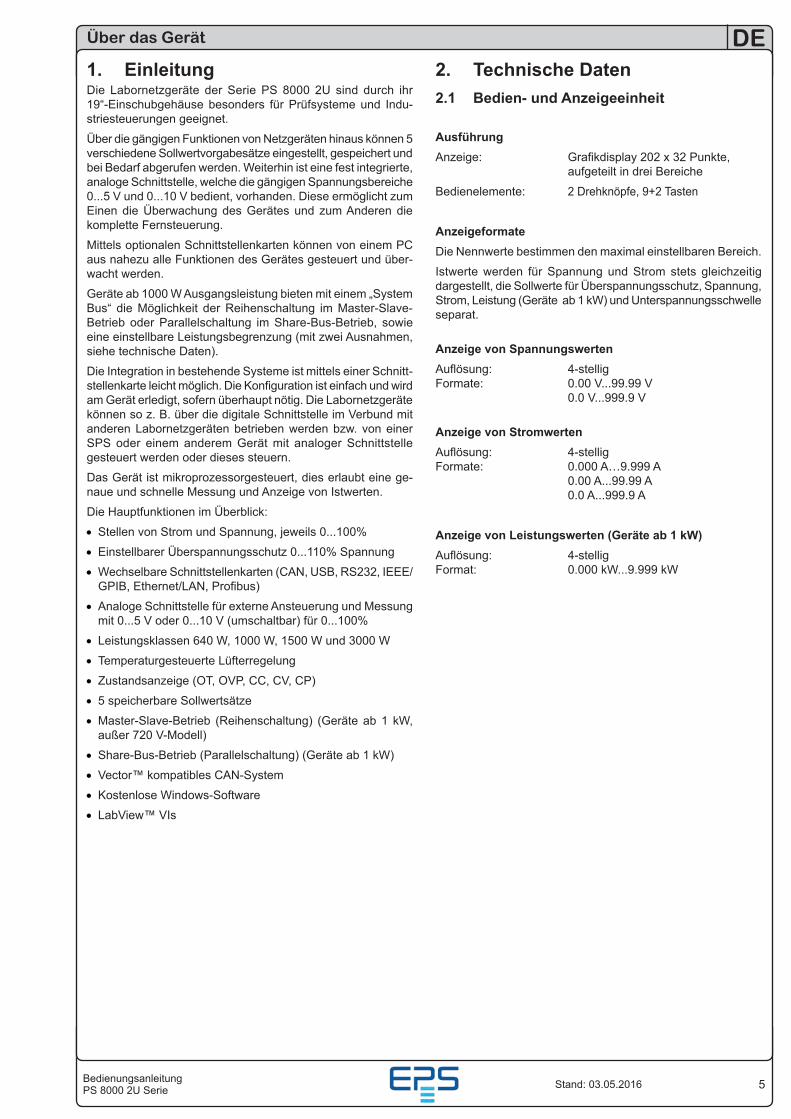
2. Technische Daten2.1 Bedien- und Anzeigeeinheit
AusführungAnzeige: Grafikdisplay 202 x 32 Punkte, aufgeteilt in drei Bereiche
Bedienelemente: 2 Drehknöpfe, 9+2 Tasten
Anzeigeformate
Die Nennwerte bestimmen den maximal einstellbaren Bereich.
Istwerte werden für Spannung und Strom stets gleichzeitig dargestellt, die Sollwerte für Überspannungsschutz, Spannung, Strom, Leistung (Geräte ab 1 kW) und Unterspannungsschwelle separat.
Anzeige von SpannungswertenAuflösung: 4-stellig Formate: 0.00 V...99.99 V 0.0 V...999.9 V
Anzeige von StromwertenAuflösung: 4-stellig Formate: 0.000 A…9.999 A 0.00 A...99.99 A 0.0 A...999.9 A
Anzeige von Leistungswerten (Geräte ab 1 kW)Auflösung: 4-stellig Format: 0.000 kW...9.999 kW
6
DE
BedienungsanleitungPS 8000 2U SerieStand: 03.05.2016
Über das Gerät
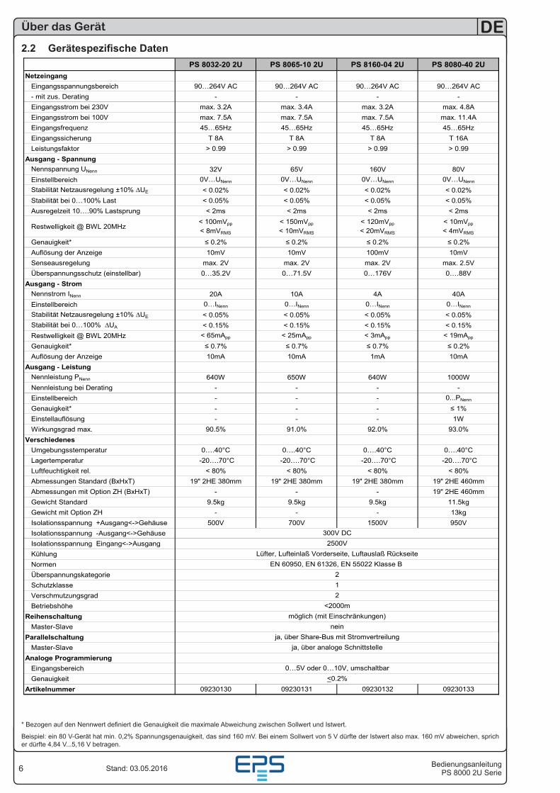
2.2 Gerätespezifische DatenPS 8032-20 2U PS 8065-10 2U PS 8160-04 2U PS 8080-40 2U
NetzeingangEingangsspannungsbereich 90…264V AC 90…264V AC 90…264V AC 90…264V AC- mit zus. Derating - - - -Eingangsstrom bei 230V max. 3.2A max. 3.4A max. 3.2A max. 4.8AEingangsstrom bei 100V max. 7.5A max. 7.5A max. 7.5A max. 11.4AEingangsfrequenz 45…65Hz 45…65Hz 45…65Hz 45…65HzEingangssicherung T 8A T 8A T 8A T 16ALeistungsfaktor > 0.99 > 0.99 > 0.99 > 0.99
Ausgang - SpannungNennspannung UNenn 32V 65V 160V 80VEinstellbereich 0V…UNenn 0V…UNenn 0V…UNenn 0V…UNenn
Stabilität Netzausregelung ±10% ∆UE < 0.02% < 0.02% < 0.02% < 0.02%Stabilität bei 0…100% Last < 0.05% < 0.05% < 0.05% < 0.05%Ausregelzeit 10….90% Lastsprung < 2ms < 2ms < 2ms < 2ms
Restwelligkeit @ BWL 20MHz< 100mVpp
< 8mVRMS
< 150mVpp
< 10mVRMS
< 120mVpp
< 20mVRMS
< 10mVpp
< 4mVRMS
Genauigkeit* ≤ 0.2% ≤ 0.2% ≤ 0.2% ≤ 0.2%Auflösung der Anzeige 10mV 10mV 100mV 10mVSenseausregelung max. 2V max. 2V max. 2V max. 2.5VÜberspannungsschutz (einstellbar) 0…35.2V 0…71.5V 0…176V 0….88V
Ausgang - StromNennstrom INenn 20A 10A 4A 40AEinstellbereich 0…INenn 0…INenn 0…INenn 0…INenn
Stabilität Netzausregelung ±10% ∆UE < 0.05% < 0.05% < 0.05% < 0.05%Stabilität bei 0…100% ∆UA < 0.15% < 0.15% < 0.15% < 0.15%Restwelligkeit @ BWL 20MHz < 65mApp < 25mApp < 3mApp < 19mApp
Genauigkeit* ≤ 0.7% ≤ 0.7% ≤ 0.7% ≤ 0.2%Auflösung der Anzeige 10mA 10mA 1mA 10mA
Ausgang - LeistungNennleistung PNenn 640W 650W 640W 1000WNennleistung bei Derating - - - -Einstellbereich - - - 0...PNenn
Genauigkeit* - - - ≤ 1%Einstellauflösung - - - 1WWirkungsgrad max. 90.5% 91.0% 92.0% 93.0%
VerschiedenesUmgebungsstemperatur 0….40°C 0….40°C 0….40°C 0….40°CLagertemperatur -20….70°C -20….70°C -20….70°C -20….70°CLuftfeuchtigkeit rel. < 80% < 80% < 80% < 80%Abmessungen Standard (BxHxT) 19" 2HE 380mm 19" 2HE 380mm 19" 2HE 380mm 19" 2HE 460mmAbmessungen mit Option ZH (BxHxT) - - - 19" 2HE 460mmGewicht Standard 9.5kg 9.5kg 9.5kg 11.5kgGewicht mit Option ZH - - - 13kgIsolationsspannung +Ausgang<->Gehäuse 500V 700V 1500V 950VIsolationsspannung -Ausgang<->GehäuseIsolationsspannung Eingang<->AusgangKühlungNormenÜberspannungskategorieSchutzklasseVerschmutzungsgradBetriebshöhe
ReihenschaltungMaster-Slave
ParallelschaltungMaster-Slave
Analoge ProgrammierungEingangsbereichGenauigkeit
Artikelnummer 09230130 09230131 09230132 09230133
0…5V oder 0…10V, umschaltbar<0.2%
neinja, über Share-Bus mit Stromvertreilung
ja, über analoge Schnittstelle
12
<2000mmöglich (mit Einschränkungen)
2500VLüfter, Lufteinlaß Vorderseite, Luftauslaß Rückseite
EN 60950, EN 61326, EN 55022 Klasse B 2
300V DC
* Bezogen auf den Nennwert definiert die Genauigkeit die maximale Abweichung zwischen Sollwert und Istwert.
Beispiel: ein 80 V-Gerät hat min. 0,2% Spannungsgenauigkeit, das sind 160 mV. Bei einem Sollwert von 5 V dürfte der Istwert also max. 160 mV abweichen, sprich er dürfte 4,84 V...5,16 V betragen.
7BedienungsanleitungPS 8000 2U Serie
DE
Stand: 03.05.2016
Über das Gerät
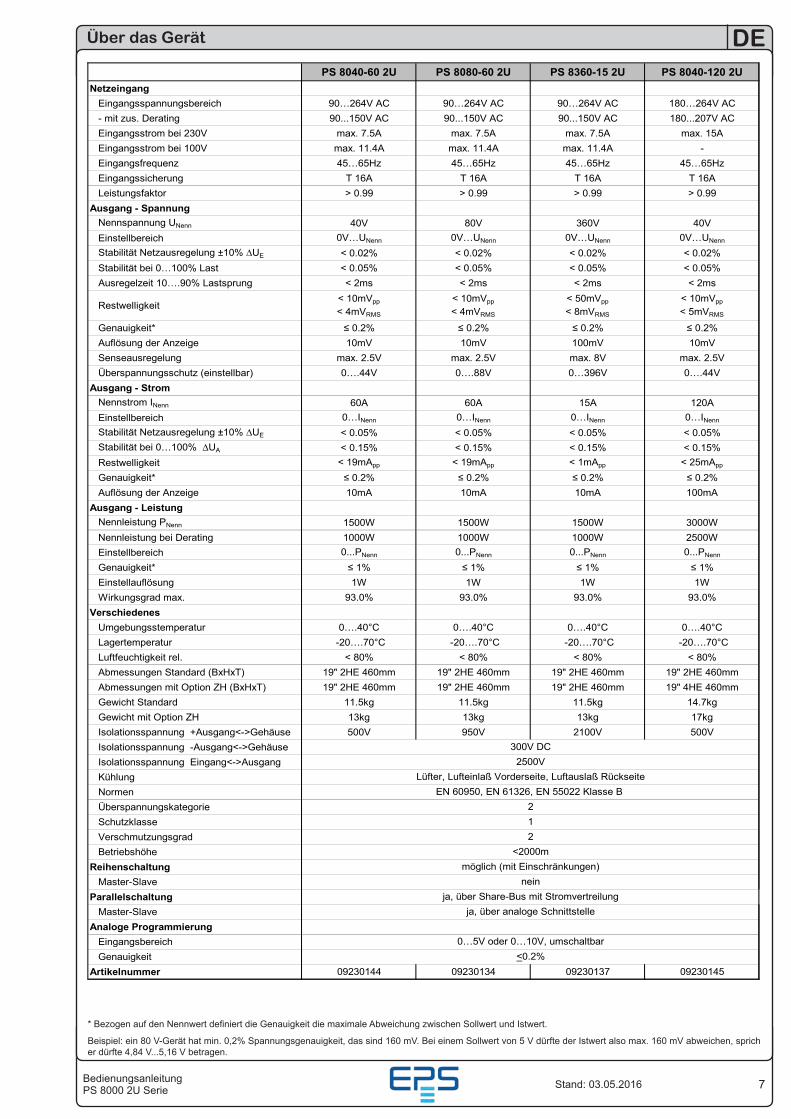
PS 8040-60 2U PS 8080-60 2U PS 8360-15 2U PS 8040-120 2UNetzeingang
Eingangsspannungsbereich 90…264V AC 90…264V AC 90…264V AC 180…264V AC- mit zus. Derating 90...150V AC 90...150V AC 90...150V AC 180...207V ACEingangsstrom bei 230V max. 7.5A max. 7.5A max. 7.5A max. 15AEingangsstrom bei 100V max. 11.4A max. 11.4A max. 11.4A -Eingangsfrequenz 45…65Hz 45…65Hz 45…65Hz 45…65HzEingangssicherung T 16A T 16A T 16A T 16ALeistungsfaktor > 0.99 > 0.99 > 0.99 > 0.99
Ausgang - SpannungNennspannung UNenn 40V 80V 360V 40VEinstellbereich 0V…UNenn 0V…UNenn 0V…UNenn 0V…UNenn
Stabilität Netzausregelung ±10% ∆UE < 0.02% < 0.02% < 0.02% < 0.02%Stabilität bei 0…100% Last < 0.05% < 0.05% < 0.05% < 0.05%Ausregelzeit 10….90% Lastsprung < 2ms < 2ms < 2ms < 2ms
Restwelligkeit< 10mVpp
< 4mVRMS
< 10mVpp
< 4mVRMS
< 50mVpp
< 8mVRMS
< 10mVpp
< 5mVRMS
Genauigkeit* ≤ 0.2% ≤ 0.2% ≤ 0.2% ≤ 0.2%Auflösung der Anzeige 10mV 10mV 100mV 10mVSenseausregelung max. 2.5V max. 2.5V max. 8V max. 2.5VÜberspannungsschutz (einstellbar) 0….44V 0….88V 0…396V 0….44V
Ausgang - StromNennstrom INenn 60A 60A 15A 120AEinstellbereich 0…INenn 0…INenn 0…INenn 0…INenn
Stabilität Netzausregelung ±10% ∆UE < 0.05% < 0.05% < 0.05% < 0.05%Stabilität bei 0…100% ∆UA < 0.15% < 0.15% < 0.15% < 0.15%Restwelligkeit < 19mApp < 19mApp < 1mApp < 25mApp
Genauigkeit* ≤ 0.2% ≤ 0.2% ≤ 0.2% ≤ 0.2%Auflösung der Anzeige 10mA 10mA 10mA 100mA
Ausgang - LeistungNennleistung PNenn 1500W 1500W 1500W 3000WNennleistung bei Derating 1000W 1000W 1000W 2500WEinstellbereich 0...PNenn 0...PNenn 0...PNenn 0...PNenn
Genauigkeit* ≤ 1% ≤ 1% ≤ 1% ≤ 1%Einstellauflösung 1W 1W 1W 1WWirkungsgrad max. 93.0% 93.0% 93.0% 93.0%
VerschiedenesUmgebungsstemperatur 0….40°C 0….40°C 0….40°C 0….40°CLagertemperatur -20….70°C -20….70°C -20….70°C -20….70°CLuftfeuchtigkeit rel. < 80% < 80% < 80% < 80%Abmessungen Standard (BxHxT) 19" 2HE 460mm 19" 2HE 460mm 19" 2HE 460mm 19" 2HE 460mmAbmessungen mit Option ZH (BxHxT) 19" 2HE 460mm 19" 2HE 460mm 19" 2HE 460mm 19" 4HE 460mmGewicht Standard 11.5kg 11.5kg 11.5kg 14.7kgGewicht mit Option ZH 13kg 13kg 13kg 17kgIsolationsspannung +Ausgang<->Gehäuse 500V 950V 2100V 500VIsolationsspannung -Ausgang<->GehäuseIsolationsspannung Eingang<->AusgangKühlungNormenÜberspannungskategorieSchutzklasseVerschmutzungsgradBetriebshöhe
ReihenschaltungMaster-Slave
ParallelschaltungMaster-Slave
Analoge ProgrammierungEingangsbereichGenauigkeit
Artikelnummer 09230144 09230134 09230137 09230145
Lüfter, Lufteinlaß Vorderseite, Luftauslaß RückseiteEN 60950, EN 61326, EN 55022 Klasse B
2
0…5V oder 0…10V, umschaltbar<0.2%
neinja, über Share-Bus mit Stromvertreilung
12
<2000mmöglich (mit Einschränkungen)
300V DC
ja, über analoge Schnittstelle
2500V
* Bezogen auf den Nennwert definiert die Genauigkeit die maximale Abweichung zwischen Sollwert und Istwert.
Beispiel: ein 80 V-Gerät hat min. 0,2% Spannungsgenauigkeit, das sind 160 mV. Bei einem Sollwert von 5 V dürfte der Istwert also max. 160 mV abweichen, sprich er dürfte 4,84 V...5,16 V betragen.
8
DE
BedienungsanleitungPS 8000 2U SerieStand: 03.05.2016
Über das Gerät
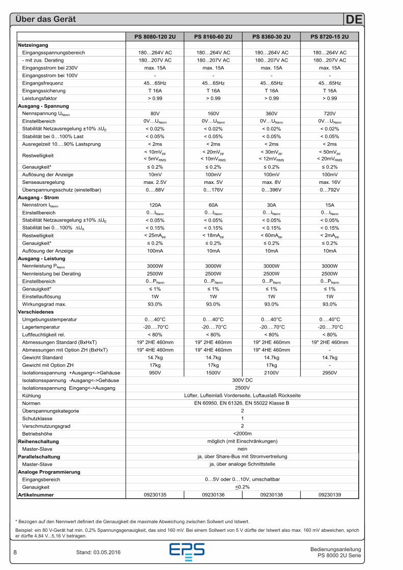
PS 8080-120 2U PS 8160-60 2U PS 8360-30 2U PS 8720-15 2UNetzeingang
Eingangsspannungsbereich 180…264V AC 180…264V AC 180…264V AC 180…264V AC- mit zus. Derating 180...207V AC 180...207V AC 180...207V AC 180...207V ACEingangsstrom bei 230V max. 15A max. 15A max. 15A max. 15AEingangsstrom bei 100V - - - -Eingangsfrequenz 45…65Hz 45…65Hz 45…65Hz 45…65HzEingangssicherung T 16A T 16A T 16A T 16ALeistungsfaktor > 0.99 > 0.99 > 0.99 > 0.99
Ausgang - SpannungNennspannung UNenn 80V 160V 360V 720VEinstellbereich 0V…UNenn 0V…UNenn 0V…UNenn 0V…UNenn
Stabilität Netzausregelung ±10% ∆UE < 0.02% < 0.02% < 0.02% < 0.02%Stabilität bei 0…100% Last < 0.05% < 0.05% < 0.05% < 0.05%Ausregelzeit 10….90% Lastsprung < 2ms < 2ms < 2ms < 2ms
Restwelligkeit< 10mVpp
< 5mVRMS
< 20mVpp
< 10mVRMS
< 30mVpp
< 12mVRMS
< 50mVpp
< 20mVRMS
Genauigkeit* ≤ 0.2% ≤ 0.2% ≤ 0.2% ≤ 0.2%Auflösung der Anzeige 10mV 100mV 100mV 100mVSenseausregelung max. 2.5V max. 5V max. 8V max. 16VÜberspannungsschutz (einstellbar) 0….88V 0…176V 0…396V 0…792V
Ausgang - StromNennstrom INenn 120A 60A 30A 15AEinstellbereich 0…INenn 0…INenn 0…INenn 0…INenn
Stabilität Netzausregelung ±10% ∆UE < 0.05% < 0.05% < 0.05% < 0.05%Stabilität bei 0…100% ∆UA < 0.15% < 0.15% < 0.15% < 0.15%Restwelligkeit < 25mApp < 18mApp < 60mApp < 2mApp
Genauigkeit* ≤ 0.2% ≤ 0.2% ≤ 0.2% ≤ 0.2%Auflösung der Anzeige 100mA 10mA 10mA 10mA
Ausgang - LeistungNennleistung PNenn 3000W 3000W 3000W 3000WNennleistung bei Derating 2500W 2500W 2500W 2500WEinstellbereich 0...PNenn 0...PNenn 0...PNenn 0...PNenn
Genauigkeit* ≤ 1% ≤ 1% ≤ 1% ≤ 1%Einstellauflösung 1W 1W 1W 1WWirkungsgrad max. 93.0% 93.0% 93.0% 93.0%
VerschiedenesUmgebungsstemperatur 0….40°C 0….40°C 0….40°C 0….40°CLagertemperatur -20….70°C -20….70°C -20….70°C -20….70°CLuftfeuchtigkeit rel. < 80% < 80% < 80% < 80%Abmessungen Standard (BxHxT) 19" 2HE 460mm 19" 2HE 460mm 19" 2HE 460mm 19" 2HE 460mmAbmessungen mit Option ZH (BxHxT) 19" 4HE 460mm 19" 4HE 460mm 19" 4HE 460mm -Gewicht Standard 14.7kg 14.7kg 14.7kg 14.7kgGewicht mit Option ZH 17kg 17kg 17kg -Isolationsspannung +Ausgang<->Gehäuse 950V 1500V 2100V 2950VIsolationsspannung -Ausgang<->GehäuseIsolationsspannung Eingang<->AusgangKühlungNormenÜberspannungskategorieSchutzklasseVerschmutzungsgradBetriebshöhe
ReihenschaltungMaster-Slave
ParallelschaltungMaster-Slave
Analoge ProgrammierungEingangsbereichGenauigkeit
Artikelnummer 09230135 09230136 09230138 09230139
<2000m
300V DC
ja, über analoge Schnittstelle
12
EN 60950, EN 61326, EN 55022 Klasse B 2
möglich (mit Einschränkungen)
2500VLüfter, Lufteinlaß Vorderseite, Luftauslaß Rückseite
0…5V oder 0…10V, umschaltbar<0.2%
neinja, über Share-Bus mit Stromvertreilung
* Bezogen auf den Nennwert definiert die Genauigkeit die maximale Abweichung zwischen Sollwert und Istwert.
Beispiel: ein 80 V-Gerät hat min. 0,2% Spannungsgenauigkeit, das sind 160 mV. Bei einem Sollwert von 5 V dürfte der Istwert also max. 160 mV abweichen, sprich er dürfte 4,84 V...5,16 V betragen.
9BedienungsanleitungPS 8000 2U Serie
DE
Stand: 03.05.2016
Über das Gerät
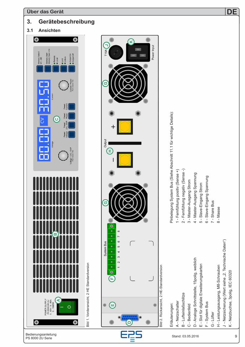
3. Gerätebeschreibung3.1 Ansichten
Bild
1. V
orde
rans
icht
, 2 H
E S
tand
ardv
ersi
on
Erlä
uter
unge
n:
P
inbe
legu
ng S
yste
m B
us (S
iehe
Abs
chni
tt 11
.1 fü
r wic
htig
e D
etai
ls):
A - N
etzs
chal
ter
1
- Fer
nfüh
lung
pos
itiv
(Sen
se +
)B
- Lu
ftein
laßs
chlit
ze
2 - F
ernf
ühlu
ng n
egat
iv (S
ense
-)C
- B
edie
nfel
d
3 - M
aste
r-A
usga
ng S
trom
D -
Ana
loge
Sch
nitts
telle
, 15p
olig
, wei
blic
h
4
- Mas
ter-
Aus
gang
Spa
nnun
gE
- S
lot f
ür d
igita
le E
rwei
teru
ngsk
arte
n
5
- Sla
ve-E
inga
ng S
trom
F - S
yste
m B
us
6
- Sla
ve-E
inga
ng S
pann
ung
G -
Lüfte
r
7 - S
hare
Bus
H -
Leis
tung
saus
gang
, M8-
Sch
raub
en
8 - M
asse
J - N
etzs
iche
rung
(Wer
t sie
he „2
. Tec
hnis
che
Dat
en“)
K -
Net
zbuc
hse,
3po
lig, I
EC
603
20
Bild
2. R
ücka
nsic
ht, 2
HE
-Sta
ndar
dver
sion
10
DE
BedienungsanleitungPS 8000 2U SerieStand: 03.05.2016
Über das Gerät
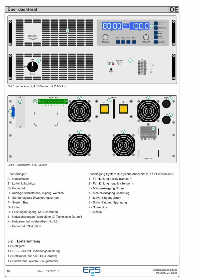
Bild 3. Vorderansicht, 4 HE-Version mit ZH-Option
Erläuterungen: Pinbelegung System Bus (Siehe Abschnitt 11.1 für Einzelheiten):A - Netzschalter 1 - Fernfühlung positiv (Sense +)B - Lufteinlaßschlitze 2 - Fernfühlung negativ (Sense -)C - Bedienfeld 3 - Master-Ausgang StromD - Analoge Schnittstelle, 15polig, weiblich 4 - Master-Ausgang SpannungE - Slot für digitale Erweiterungskarten 5 - Slave-Eingang StromF - System Bus 6 - Slave-Eingang SpannungG - Lüfter 7 - Share BusH - Leistungsausgang, M8-Schrauben 8 - MasseJ - Netzsicherungen (Wert siehe „2. Technische Daten“)K - Netzanschluß (siehe Abschnitt 5.3)L - Bedienfeld ZH-Option
Bild 4. Rückansicht, 4 HE-Version
3.2 Lieferumfang1 x Netzgerät
1 x USB-Stick mit Bedienungsanleitung
1 x Netzkabel (nur bei 2 HE-Geräten)
1 x Stecker für System Bus (gesteckt)
11BedienungsanleitungPS 8000 2U Serie
DE
Stand: 03.05.2016
Über das Gerät
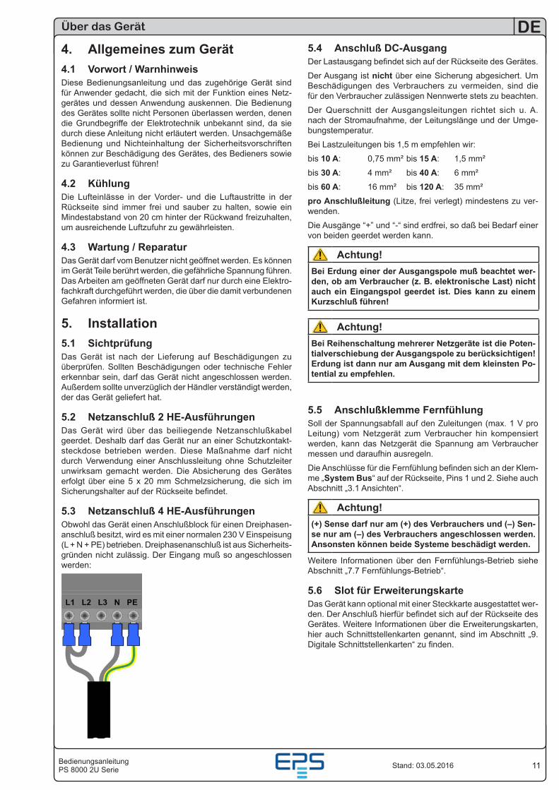
5.4 Anschluß DC-AusgangDer Lastausgang befindet sich auf der Rückseite des Gerätes.
Der Ausgang ist nicht über eine Sicherung abgesichert. Um Beschädigungen des Verbrauchers zu vermeiden, sind die für den Verbraucher zulässigen Nennwerte stets zu beachten.
Der Querschnitt der Ausgangsleitungen richtet sich u. A. nach der Stromaufnahme, der Leitungslänge und der Umge-bungstemperatur.
Bei Lastzuleitungen bis 1,5 m empfehlen wir:
bis 10 A: 0,75 mm² bis 15 A: 1,5 mm²
bis 30 A: 4 mm² bis 40 A: 6 mm²
bis 60 A: 16 mm² bis 120 A: 35 mm²
pro Anschlußleitung (Litze, frei verlegt) mindestens zu ver-wenden.
Die Ausgänge “+” und “-“ sind erdfrei, so daß bei Bedarf einer von beiden geerdet werden kann.
Achtung!Bei Erdung einer der Ausgangspole muß beachtet wer-den, ob am Verbraucher (z. B. elektronische Last) nicht auch ein Eingangspol geerdet ist. Dies kann zu einem Kurzschluß führen!
Achtung!Bei Reihenschaltung mehrerer Netzgeräte ist die Poten-tialverschiebung der Ausgangspole zu berücksichtigen! Erdung ist dann nur am Ausgang mit dem kleinsten Po-tential zu empfehlen.
5.5 Anschlußklemme Fernfühlung Soll der Spannungsabfall auf den Zuleitungen (max. 1 V pro Leitung) vom Netzgerät zum Verbraucher hin kompensiert werden, kann das Netzgerät die Spannung am Verbraucher messen und daraufhin ausregeln.
Die Anschlüsse für die Fernfühlung befinden sich an der Klem-me „System Bus“ auf der Rückseite, Pins 1 und 2. Siehe auch Abschnitt „3.1 Ansichten“.
Achtung!(+) Sense darf nur am (+) des Verbrauchers und (–) Sen-se nur am (–) des Verbrauchers angeschlossen werden. Ansonsten können beide Systeme beschädigt werden.
Weitere Informationen über den Fernfühlungs-Betrieb siehe Abschnitt „7.7 Fernfühlungs-Betrieb“.
5.6 Slot für ErweiterungskarteDas Gerät kann optional mit einer Steckkarte ausgestattet wer-den. Der Anschluß hierfür befindet sich auf der Rückseite des Gerätes. Weitere Informationen über die Erweiterungskarten, hier auch Schnittstellenkarten genannt, sind im Abschnitt „9. Digitale Schnittstellenkarten“ zu finden.
4. Allgemeines zum Gerät4.1 Vorwort / WarnhinweisDiese Bedienungsanleitung und das zugehörige Gerät sind für Anwender gedacht, die sich mit der Funktion eines Netz-gerätes und dessen Anwendung auskennen. Die Bedienung des Gerätes sollte nicht Personen überlassen werden, denen die Grundbegriffe der Elektrotechnik unbekannt sind, da sie durch diese Anleitung nicht erläutert werden. Unsachgemäße Bedienung und Nichteinhaltung der Sicherheitsvorschriften können zur Beschädigung des Gerätes, des Bedieners sowie zu Garantieverlust führen!
4.2 KühlungDie Lufteinlässe in der Vorder- und die Luftaustritte in der Rückseite sind immer frei und sauber zu halten, sowie ein Mindestabstand von 20 cm hinter der Rückwand freizuhalten, um ausreichende Luftzufuhr zu gewährleisten.
4.3 Wartung / ReparaturDas Gerät darf vom Benutzer nicht geöffnet werden. Es können im Gerät Teile berührt werden, die gefährliche Spannung führen. Das Arbeiten am geöffneten Gerät darf nur durch eine Elektro-fachkraft durchgeführt werden, die über die damit verbundenen Gefahren informiert ist.
5. Installation5.1 SichtprüfungDas Gerät ist nach der Lieferung auf Beschädigungen zu überprüfen. Sollten Beschädigungen oder technische Fehler erkennbar sein, darf das Gerät nicht angeschlossen werden. Außerdem sollte unverzüglich der Händler verständigt werden, der das Gerät geliefert hat.
5.2 Netzanschluß 2 HE-AusführungenDas Gerät wird über das beiliegende Netzanschlußkabel geerdet. Deshalb darf das Gerät nur an einer Schutzkontakt-steckdose betrieben werden. Diese Maßnahme darf nicht durch Verwendung einer Anschlussleitung ohne Schutzleiter unwirksam gemacht werden. Die Absicherung des Gerätes erfolgt über eine 5 x 20 mm Schmelzsicherung, die sich im Sicherungshalter auf der Rückseite befindet.
5.3 Netzanschluß 4 HE-AusführungenObwohl das Gerät einen Anschlußblock für einen Dreiphasen-anschluß besitzt, wird es mit einer normalen 230 V Einspeisung (L + N + PE) betrieben. Dreiphasenanschluß ist aus Sicherheits-gründen nicht zulässig. Der Eingang muß so angeschlossen werden:
12
DE
BedienungsanleitungPS 8000 2U SerieStand: 03.05.2016
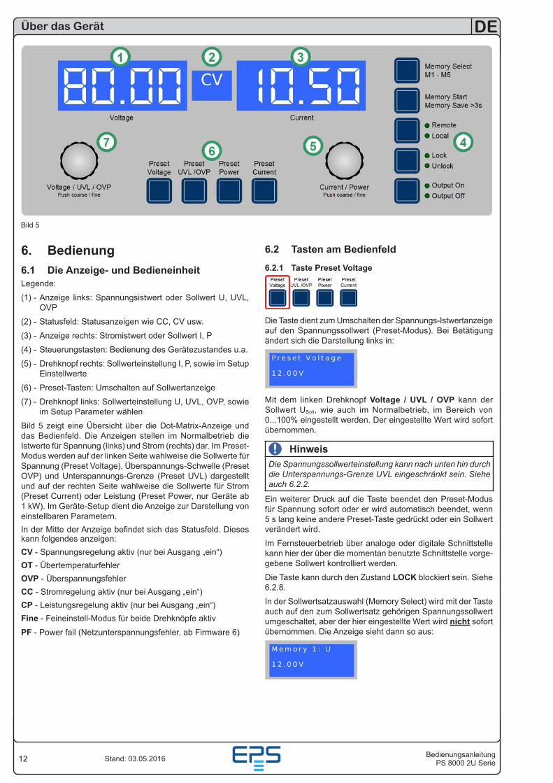
6. Bedienung6.1 Die Anzeige- und BedieneinheitLegende:
(1) - Anzeige links: Spannungsistwert oder Sollwert U, UVL, OVP
(2) - Statusfeld: Statusanzeigen wie CC, CV usw.
(3) - Anzeige rechts: Stromistwert oder Sollwert I, P
(4) - Steuerungstasten: Bedienung des Gerätezustandes u.a.
(5) - Drehknopf rechts: Sollwerteinstellung I, P, sowie im Setup Einstellwerte
(6) - Preset-Tasten: Umschalten auf Sollwertanzeige
(7) - Drehknopf links: Sollwerteinstellung U, UVL, OVP, sowie im Setup Parameter wählen
Bild 5 zeigt eine Übersicht über die Dot-Matrix-Anzeige und das Bedienfeld. Die Anzeigen stellen im Normalbetrieb die Istwerte für Spannung (links) und Strom (rechts) dar. Im Preset-Modus werden auf der linken Seite wahlweise die Sollwerte für Spannung (Preset Voltage), Überspannungs-Schwelle (Preset OVP) und Unterspannungs-Grenze (Preset UVL) dargestellt und auf der rechten Seite wahlweise die Sollwerte für Strom (Preset Current) oder Leistung (Preset Power, nur Geräte ab 1 kW). Im Geräte-Setup dient die Anzeige zur Darstellung von einstellbaren Parametern.In der Mitte der Anzeige befindet sich das Statusfeld. Dieses kann folgendes anzeigen:CV - Spannungsregelung aktiv (nur bei Ausgang „ein“)OT - ÜbertemperaturfehlerOVP - ÜberspannungsfehlerCC - Stromregelung aktiv (nur bei Ausgang „ein“)CP - Leistungsregelung aktiv (nur bei Ausgang „ein“)Fine - Feineinstell-Modus für beide Drehknöpfe aktiv
PF - Power fail (Netzunterspannungsfehler, ab Firmware 6)
Über das Gerät
Bild 5
6.2 Tasten am Bedienfeld
6.2.1 Taste Preset Voltage
Die Taste dient zum Umschalten der Spannungs-Istwertanzeige auf den Spannungssollwert (Preset-Modus). Bei Betätigung ändert sich die Darstellung links in:
Mit dem linken Drehknopf Voltage / UVL / OVP kann der Sollwert USoll, wie auch im Normalbetrieb, im Bereich von 0...100% eingestellt werden. Der eingestellte Wert wird sofort übernommen.
HinweisDie Spannungssollwerteinstellung kann nach unten hin durch die Unterspannungs-Grenze UVL eingeschränkt sein. Siehe auch 6.2.2.
Ein weiterer Druck auf die Taste beendet den Preset-Modus für Spannung sofort oder er wird automatisch beendet, wenn 5 s lang keine andere Preset-Taste gedrückt oder ein Sollwert verändert wird.
Im Fernsteuerbetrieb über analoge oder digitale Schnittstelle kann hier der über die momentan benutzte Schnittstelle vorge-gebene Sollwert kontrolliert werden.
Die Taste kann durch den Zustand LOCK blockiert sein. Siehe 6.2.8.
In der Sollwertsatzauswahl (Memory Select) wird mit der Taste auch auf den zum Sollwertsatz gehörigen Spannungssollwert umgeschaltet, aber der hier eingestellte Wert wird nicht sofort übernommen. Die Anzeige sieht dann so aus:
13BedienungsanleitungPS 8000 2U Serie
DE
Stand: 03.05.2016
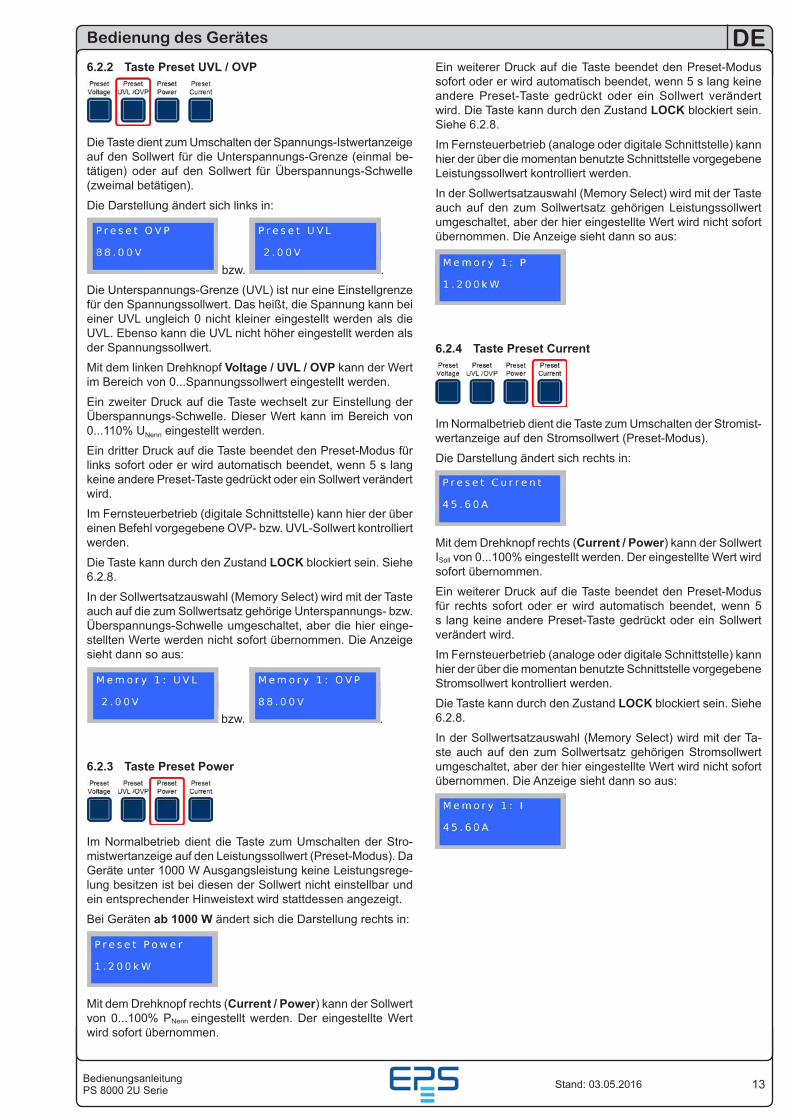
6.2.2 Taste Preset UVL / OVP
Die Taste dient zum Umschalten der Spannungs-Istwertanzeige auf den Sollwert für die Unterspannungs-Grenze (einmal be-tätigen) oder auf den Sollwert für Überspannungs-Schwelle (zweimal betätigen).
Die Darstellung ändert sich links in:
bzw. .
Die Unterspannungs-Grenze (UVL) ist nur eine Einstellgrenze für den Spannungssollwert. Das heißt, die Spannung kann bei einer UVL ungleich 0 nicht kleiner eingestellt werden als die UVL. Ebenso kann die UVL nicht höher eingestellt werden als der Spannungssollwert.
Mit dem linken Drehknopf Voltage / UVL / OVP kann der Wert im Bereich von 0...Spannungssollwert eingestellt werden.
Ein zweiter Druck auf die Taste wechselt zur Einstellung der Überspannungs-Schwelle. Dieser Wert kann im Bereich von 0...110% UNenn eingestellt werden.
Ein dritter Druck auf die Taste beendet den Preset-Modus für links sofort oder er wird automatisch beendet, wenn 5 s lang keine andere Preset-Taste gedrückt oder ein Sollwert verändert wird.
Im Fernsteuerbetrieb (digitale Schnittstelle) kann hier der über einen Befehl vorgegebene OVP- bzw. UVL-Sollwert kontrolliert werden.
Die Taste kann durch den Zustand LOCK blockiert sein. Siehe 6.2.8.
In der Sollwertsatzauswahl (Memory Select) wird mit der Taste auch auf die zum Sollwertsatz gehörige Unterspannungs- bzw. Überspannungs-Schwelle umgeschaltet, aber die hier einge-stellten Werte werden nicht sofort übernommen. Die Anzeige sieht dann so aus:
bzw. .
6.2.3 Taste Preset Power
Im Normalbetrieb dient die Taste zum Umschalten der Stro-mistwertanzeige auf den Leistungssollwert (Preset-Modus). Da Geräte unter 1000 W Ausgangsleistung keine Leistungsrege-lung besitzen ist bei diesen der Sollwert nicht einstellbar und ein entsprechender Hinweistext wird stattdessen angezeigt.
Bei Geräten ab 1000 W ändert sich die Darstellung rechts in:
Mit dem Drehknopf rechts (Current / Power) kann der Sollwert von 0...100% PNenn eingestellt werden. Der eingestellte Wert wird sofort übernommen.
Bedienung des Gerätes
Ein weiterer Druck auf die Taste beendet den Preset-Modus sofort oder er wird automatisch beendet, wenn 5 s lang keine andere Preset-Taste gedrückt oder ein Sollwert verändert wird. Die Taste kann durch den Zustand LOCK blockiert sein. Siehe 6.2.8.
Im Fernsteuerbetrieb (analoge oder digitale Schnittstelle) kann hier der über die momentan benutzte Schnittstelle vorgegebene Leistungssollwert kontrolliert werden.
In der Sollwertsatzauswahl (Memory Select) wird mit der Taste auch auf den zum Sollwertsatz gehörigen Leistungssollwert umgeschaltet, aber der hier eingestellte Wert wird nicht sofort übernommen. Die Anzeige sieht dann so aus:
6.2.4 Taste Preset Current
Im Normalbetrieb dient die Taste zum Umschalten der Stromist-wertanzeige auf den Stromsollwert (Preset-Modus).
Die Darstellung ändert sich rechts in:
Mit dem Drehknopf rechts (Current / Power) kann der Sollwert ISoll von 0...100% eingestellt werden. Der eingestellte Wert wird sofort übernommen.
Ein weiterer Druck auf die Taste beendet den Preset-Modus für rechts sofort oder er wird automatisch beendet, wenn 5 s lang keine andere Preset-Taste gedrückt oder ein Sollwert verändert wird.
Im Fernsteuerbetrieb (analoge oder digitale Schnittstelle) kann hier der über die momentan benutzte Schnittstelle vorgegebene Stromsollwert kontrolliert werden.
Die Taste kann durch den Zustand LOCK blockiert sein. Siehe 6.2.8.
In der Sollwertsatzauswahl (Memory Select) wird mit der Ta-ste auch auf den zum Sollwertsatz gehörigen Stromsollwert umgeschaltet, aber der hier eingestellte Wert wird nicht sofort übernommen. Die Anzeige sieht dann so aus:
14
DE
BedienungsanleitungPS 8000 2U SerieStand: 03.05.2016
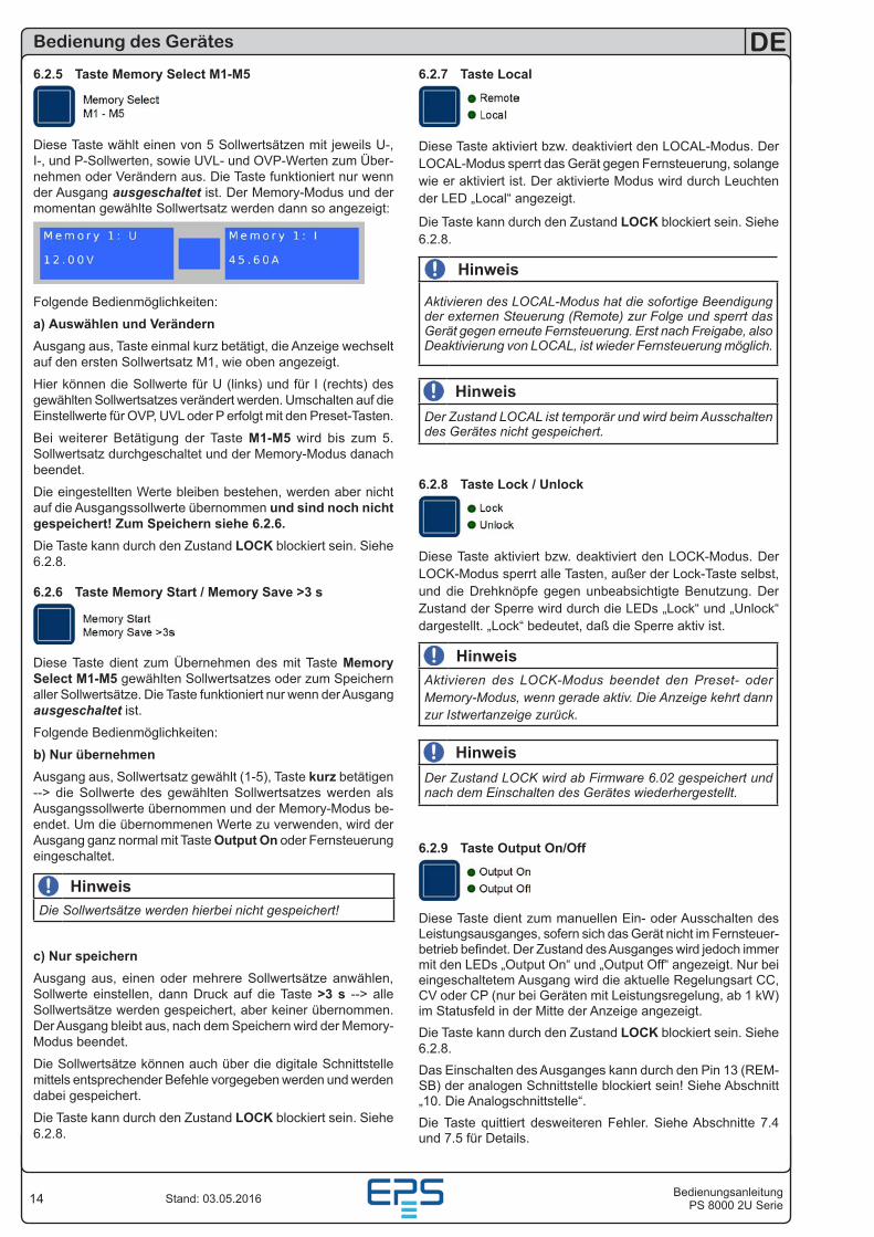
6.2.5 Taste Memory Select M1-M5
Diese Taste wählt einen von 5 Sollwertsätzen mit jeweils U-, I-, und P-Sollwerten, sowie UVL- und OVP-Werten zum Über-nehmen oder Verändern aus. Die Taste funktioniert nur wenn der Ausgang ausgeschaltet ist. Der Memory-Modus und der momentan gewählte Sollwertsatz werden dann so angezeigt:
Folgende Bedienmöglichkeiten:
a) Auswählen und VerändernAusgang aus, Taste einmal kurz betätigt, die Anzeige wechselt auf den ersten Sollwertsatz M1, wie oben angezeigt.
Hier können die Sollwerte für U (links) und für I (rechts) des gewählten Sollwertsatzes verändert werden. Umschalten auf die Einstellwerte für OVP, UVL oder P erfolgt mit den Preset-Tasten.
Bei weiterer Betätigung der Taste M1-M5 wird bis zum 5. Sollwertsatz durchgeschaltet und der Memory-Modus danach beendet.
Die eingestellten Werte bleiben bestehen, werden aber nicht auf die Ausgangssollwerte übernommen und sind noch nicht gespeichert! Zum Speichern siehe 6.2.6.Die Taste kann durch den Zustand LOCK blockiert sein. Siehe 6.2.8.
6.2.6 Taste Memory Start / Memory Save >3 s
Diese Taste dient zum Übernehmen des mit Taste Memory Select M1-M5 gewählten Sollwertsatzes oder zum Speichern aller Sollwertsätze. Die Taste funktioniert nur wenn der Ausgang ausgeschaltet ist.
Folgende Bedienmöglichkeiten:
b) Nur übernehmenAusgang aus, Sollwertsatz gewählt (1-5), Taste kurz betätigen --> die Sollwerte des gewählten Sollwertsatzes werden als Ausgangssollwerte übernommen und der Memory-Modus be-endet. Um die übernommenen Werte zu verwenden, wird der Ausgang ganz normal mit Taste Output On oder Fernsteuerung eingeschaltet.
HinweisDie Sollwertsätze werden hierbei nicht gespeichert!
c) Nur speichernAusgang aus, einen oder mehrere Sollwertsätze anwählen, Sollwerte einstellen, dann Druck auf die Taste >3 s --> alle Sollwertsätze werden gespeichert, aber keiner übernommen. Der Ausgang bleibt aus, nach dem Speichern wird der Memory-Modus beendet.
Die Sollwertsätze können auch über die digitale Schnittstelle mittels entsprechender Befehle vorgegeben werden und werden dabei gespeichert.
Die Taste kann durch den Zustand LOCK blockiert sein. Siehe 6.2.8.
Bedienung des Gerätes
6.2.7 Taste Local
Diese Taste aktiviert bzw. deaktiviert den LOCAL-Modus. Der LOCAL-Modus sperrt das Gerät gegen Fernsteuerung, solange wie er aktiviert ist. Der aktivierte Modus wird durch Leuchten der LED „Local“ angezeigt.
Die Taste kann durch den Zustand LOCK blockiert sein. Siehe 6.2.8.
Hinweis
Aktivieren des LOCAL-Modus hat die sofortige Beendigung der externen Steuerung (Remote) zur Folge und sperrt das Gerät gegen erneute Fernsteuerung. Erst nach Freigabe, also Deaktivierung von LOCAL, ist wieder Fernsteuerung möglich.
HinweisDer Zustand LOCAL ist temporär und wird beim Ausschalten des Gerätes nicht gespeichert.
6.2.8 Taste Lock / Unlock
Diese Taste aktiviert bzw. deaktiviert den LOCK-Modus. Der LOCK-Modus sperrt alle Tasten, außer der Lock-Taste selbst, und die Drehknöpfe gegen unbeabsichtigte Benutzung. Der Zustand der Sperre wird durch die LEDs „Lock“ und „Unlock“ dargestellt. „Lock“ bedeutet, daß die Sperre aktiv ist.
HinweisAktivieren des LOCK-Modus beendet den Preset- oder Memory-Modus, wenn gerade aktiv. Die Anzeige kehrt dann zur Istwertanzeige zurück.
HinweisDer Zustand LOCK wird ab Firmware 6.02 gespeichert und nach dem Einschalten des Gerätes wiederhergestellt.
6.2.9 Taste Output On/Off
Diese Taste dient zum manuellen Ein- oder Ausschalten des Leistungsausganges, sofern sich das Gerät nicht im Fernsteuer-betrieb befindet. Der Zustand des Ausganges wird jedoch immer mit den LEDs „Output On“ und „Output Off“ angezeigt. Nur bei eingeschaltetem Ausgang wird die aktuelle Regelungsart CC, CV oder CP (nur bei Geräten mit Leistungsregelung, ab 1 kW) im Statusfeld in der Mitte der Anzeige angezeigt.Die Taste kann durch den Zustand LOCK blockiert sein. Siehe 6.2.8.Das Einschalten des Ausganges kann durch den Pin 13 (REM-SB) der analogen Schnittstelle blockiert sein! Siehe Abschnitt „10. Die Analogschnittstelle“.Die Taste quittiert desweiteren Fehler. Siehe Abschnitte 7.4 und 7.5 für Details.
15BedienungsanleitungPS 8000 2U Serie
DE
Stand: 03.05.2016
Bedienung des Gerätes
6.3 Weitere Bedienelemente
6.3.1 Drehknöpfe
Die beiden Drehknöpfe haben eine zusätzliche Tastfunktion. Durch Drücken einer oder beider Drehknopftasten kann fol-gendes ausgelöst werden:
a) Feineinstell-Modus (Fine)Im manuellem Betrieb aktiviert bzw. deaktiviert ein kurzer Druck auf eine der beiden Tasten den Feineinstell-Modus „Fine“. Bei aktiviertem „Fine“-Modus können alle Sollwerte mit der kleinst-möglichen Schrittweite eingestellt werden, egal ob das Gerät im Preset-, Memory- oder Istwertmodus ist. Angezeigt wird der Feineinstell-Modus durch den Text „Fine“ im Statusfeld (Mitte). Siehe auch Abschnitt „6.4 Sollwerte einstellen“ unten.
b) Geräte-SetupGleichzeitiges Drücken beider Tasten für >3 s bei ausgeschal-tetem Ausgang wechselt in das Geräte-Setup. Das Setup wird auf gleiche Weise beendet.
6.4 Sollwerte einstellen1. Im manuellen Betrieb
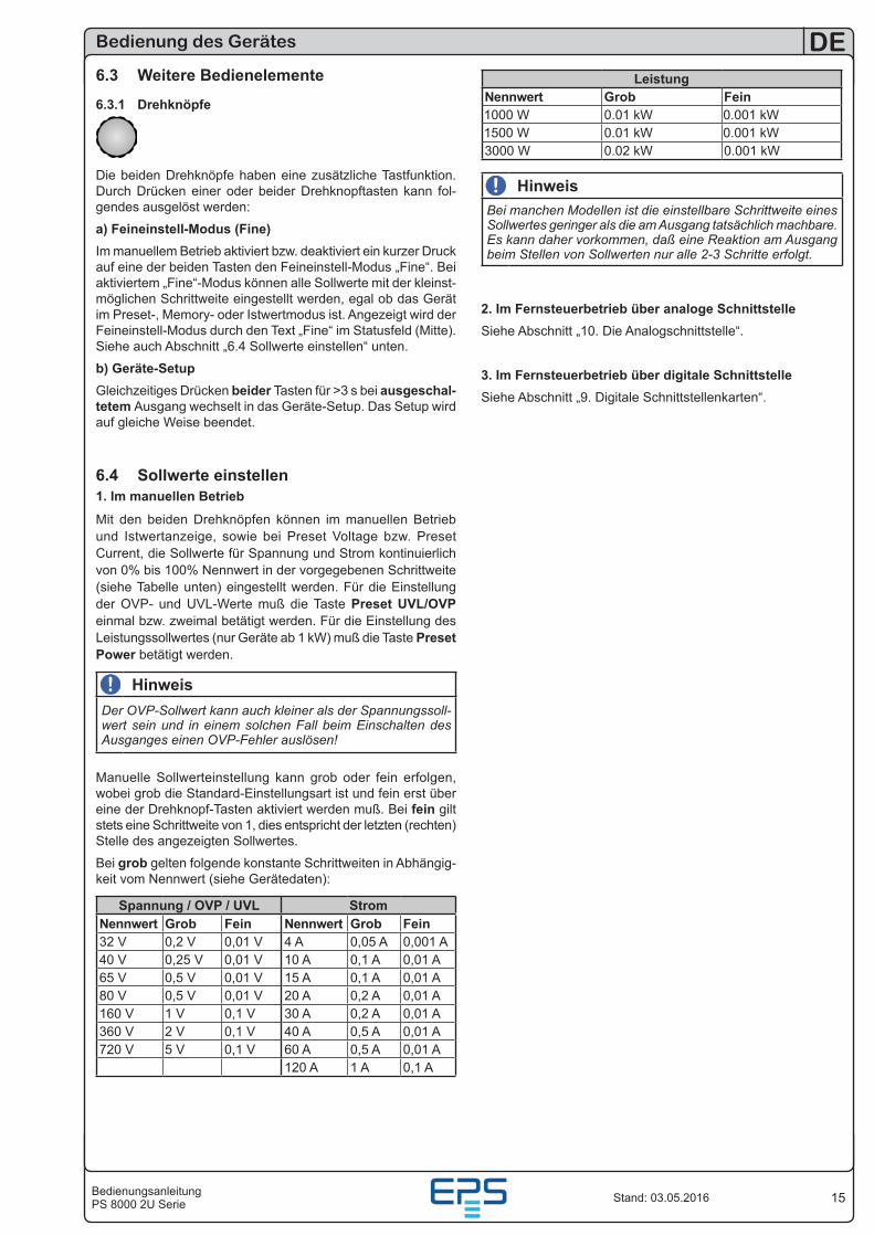
Mit den beiden Drehknöpfen können im manuellen Betrieb und Istwertanzeige, sowie bei Preset Voltage bzw. Preset Current, die Sollwerte für Spannung und Strom kontinuierlich von 0% bis 100% Nennwert in der vorgegebenen Schrittweite (siehe Tabelle unten) eingestellt werden. Für die Einstellung der OVP- und UVL-Werte muß die Taste Preset UVL/OVP einmal bzw. zweimal betätigt werden. Für die Einstellung des Leistungssollwertes (nur Geräte ab 1 kW) muß die Taste Preset Power betätigt werden.
HinweisDer OVP-Sollwert kann auch kleiner als der Spannungssoll-wert sein und in einem solchen Fall beim Einschalten des Ausganges einen OVP-Fehler auslösen!
Manuelle Sollwerteinstellung kann grob oder fein erfolgen, wobei grob die Standard-Einstellungsart ist und fein erst über eine der Drehknopf-Tasten aktiviert werden muß. Bei fein gilt stets eine Schrittweite von 1, dies entspricht der letzten (rechten) Stelle des angezeigten Sollwertes.
Bei grob gelten folgende konstante Schrittweiten in Abhängig-keit vom Nennwert (siehe Gerätedaten):
Spannung / OVP / UVL StromNennwert Grob Fein Nennwert Grob Fein32 V 0,2 V 0,01 V 4 A 0,05 A 0,001 A40 V 0,25 V 0,01 V 10 A 0,1 A 0,01 A65 V 0,5 V 0,01 V 15 A 0,1 A 0,01 A80 V 0,5 V 0,01 V 20 A 0,2 A 0,01 A160 V 1 V 0,1 V 30 A 0,2 A 0,01 A360 V 2 V 0,1 V 40 A 0,5 A 0,01 A720 V 5 V 0,1 V 60 A 0,5 A 0,01 A
120 A 1 A 0,1 A
LeistungNennwert Grob Fein1000 W 0.01 kW 0.001 kW1500 W 0.01 kW 0.001 kW3000 W 0.02 kW 0.001 kW
HinweisBei manchen Modellen ist die einstellbare Schrittweite eines Sollwertes geringer als die am Ausgang tatsächlich machbare. Es kann daher vorkommen, daß eine Reaktion am Ausgang beim Stellen von Sollwerten nur alle 2-3 Schritte erfolgt.
2. Im Fernsteuerbetrieb über analoge SchnittstelleSiehe Abschnitt „10. Die Analogschnittstelle“.
3. Im Fernsteuerbetrieb über digitale SchnittstelleSiehe Abschnitt „9. Digitale Schnittstellenkarten“.
16
DE
BedienungsanleitungPS 8000 2U SerieStand: 03.05.2016
Bedienung des Gerätes
7. Verhalten des Gerätes7.1 Einschalten mit dem NetzschalterDer Netzschalter befindet sich auf der Vorderseite. Nach dem Einschalten zeigt das Gerät in der Anzeige für etwa zwei Sekun-den Herstellername und -logo, sowie die Anschrift, Gerätetyp und Firmwareversion an und ist danach betriebsbereit. Im Setup (siehe Abschnitt „8. Geräte-Setup“) befindet sich eine Option die bestimmt, wie der Zustand des Gerätes nach dem Einschalten ist. Werkseitig ist diese aktiviert (=on). Das bedeutet, daß die Sollwerte (U, I, P) und der Zustand des Ausganges (ein oder aus) wiederhergestellt werden, so wie sie beim letzten Aus-schalten waren. Ist die Option nicht aktiviert (=off), werden die Sollwerte für U, UVL und I nach dem Einschalten auf 0, OVP auf max. und der Sollwert P auf 100% gesetzt und der Ausgang wird eingeschaltet.
7.2 Ausschalten mit dem NetzschalterBeim Ausschalten mit dem Netzschalter speichert das Gerät den Zustand des Ausganges und die zuletzt eingestellten Soll-werte. Nach kurzer Zeit werden Leistungsausgang und Lüfter abgeschaltet, das Gerät ist nach einigen weiteren Sekunden dann komplett aus.
7.3 Umschalten auf Fernsteuerung (Remote)a) Analoge Schnittstelle: Pin „Remote“ schaltet auf analoge Fernsteuerung um, sofern dies nicht durch den Zustand LOCAL bzw. eine bereits bestehende digitale Fernsteuerung verhindert wird. Die Sollwertpins VSEL, CSEL und PSEL (nur nötig bei Geräten ab 1 kW), sowie REM-SB bestimmen nun die Aus-gangswerte. Der Zustand des DC-Ausgangs und die Sollwerte, die über die Pins vorgegeben sind, werden sofort gesetzt. Nach Rückkehr aus der Fernsteuerung in die manuelle Steuerung wird der Ausgang automatisch ausgeschaltet.
b) Digitale Schnittstelle: Umschalten auf digitalen Fernsteu-erbetrieb mittels eines entsprechenden Befehls, sofern nicht durch den Zustand LOCAL oder bereits bestehende, analoge Fernsteuerung verhindert, übernimmt die zuletzt eingestellten Sollwerte und den Zustand des Ausganges. Nach Rückkehr aus der Fernsteuerung in die manuelle Steuerung wird der Ausgang automatisch ausgeschaltet.
7.4 Überspannungs-AlarmEin Überspannungs-Alarm (OV) kann auftreten durch einen internen Fehler (Ausgangsspannung läuft hoch) oder durch eine zu hohe Spannung von außen. Der Überspannungs-schutz wird in beiden Fällen das Leistungsteil und somit die Ausgangsspannung abschalten und das Gerät den Alarm durch den Statustext „OV“ anzeigen bzw. über den Pin „OVP“ an der analogen Schnittstelle melden.
Ist keine Überspannung mehr vorhanden und soll der Ausgang wieder eingeschaltet werden, muß zuerst der Alarm quittiert wer-den. Bei manuellem Betrieb geschieht dies mit der Taste Output On/Off, bei analoger Fernsteuerung mit dem Pin „Rem-SB“ und bei digitaler Fernsteuerung mit dem entsprechenden Befehl. Die Anzeige „OV“ und das Signal am Pin „OVP“ erlöschen dann. Ist der Alarm weiterhin vorhanden, kann der Ausgang nicht eingeschaltet werden.
OV-Alarme werden im internen Alarm-Puffer eingetragen, welcher über eine digitale Schnittstelle (außer jene, die SCPI-Sprache verwenden) ausgelesen werden kann.
HinweisDer OVP-Alarm hat Vorrang vor einem OT-Alarm und über-schreibt die Anzeige „OT“, sollten beide Alarme gleichzeitig auftreten.
7.5 Übertemperatur-AlarmSobald ein Übertemperatur-Alarm (OT) durch interne Überhit-zung auftritt, wird der Ausgang abgeschaltet und der Status „OT“ im Display angezeigt. Gleichzeitig blinkt die LED „Output On“ um anzuzeigen, daß sich der Ausgang nach dem Abkühlen automatisch wieder einschaltet. Soll dies nicht geschehen, kann der Ausgang während der Übertemperatur-Phase manuell mit der Taste Output On/Off abgeschaltet werden. Die LED „Output On“ blinkt dann nicht mehr und der Ausgang schaltet sich nach Abkühlung nicht automatisch ein. Ist der Ausgang aus, nachdem sich das Gerät abgekühlt hat, genügt normales Einschalten mittels Taste, Pin oder Befehl. Ist der Ausgang ein, wird mit der Taste Output On/Off, dem Pin „REM-SB“ oder einem Befehl zunächst quittiert und beim zweiten Mal ausgeschaltet.
OT-Alarme werden im internen Alarm-Puffer eingetragen-welcher über eine digitale Schnittstelle (außer jene, die SCPI-Sprache verwenden) ausgelesen werden kann.
HinweisEin OT-Alarm hat geringere Priorität als ein OV-Alarm. Sollte während eines OT-Alarms auch ein OV-Alarm auftreten, wird die Statusanzeige „OT“ mit „OV“ überschrieben.
7.6 Spannungs-, Strom- und LeistungsregelungDie am Ausgang eingestellte Spannung und der Widerstand des Verbrauchers bestimmen den Ausgangsstrom. Ist dieser kleiner als die am Gerät eingestellte Strombegrenzung, arbeitet das Gerät im Spannungsregelbetrieb (CV) und hält die Ausgangs-spannung konstant. Angezeigt wird die Betriebsart durch den Statustext „CV“.
Wird der Ausgangsstrom durch den Stromsollwert oder den Nennstrom des Gerätes begrenzt, so wechselt das Gerät in den Strom-Regelbetrieb (CC), der den Ausgangsstrom konstant hält. Diese Betriebsart wird durch den Statustext „CC“ angezeigt.
Bei Geräten ab 1000 W Ausgangsleistung gibt es zusätzlich eine einstellbare Leistungsbegrenzung von 0...PNenn. Diese überlagert Spannungs- und Strom-Regelbetrieb. Das heißt, wenn zusätzlich ein Leistungssollwert kleiner 100% PNenn gesetzt wird, können die gewünschte Ausgangsspannung und/oder der gewünschte Ausgangsstrom möglicherweise nicht erreicht werden. Die Leistungsbegrenzung beeinflußt in erster Linie die Ausgangsspannung. Der sich durch den Lastwiderstand ergebende Strom ergibt zusammen mit der Ausgangsspannung die gewünschte Ausgangsleistung. Da sich Strom-, Spannungs- und Leistungsregelung gegenseitig beeinflussen, ergäben sich z. B. folgende Verhaltensweisen:Beispiel 1: Gerät ist in Spannungsregelbetrieb, dann wird die Leistung begrenzt. Als Folge sinkt die Ausgangsspannung und als Folge davon sinkt der Ausgangsstrom. Wenn sich nun der Widerstand des Verbrauchers verringert, würde der Strom steigen und die Spannung sinken.Beispiel 2: Gerät ist in Strombegrenzung, die Ausgangsspan-nung wird vom Widerstand des Verbrauchers bestimmt. Nun wird die Leistung begrenzt, also Leistungs-Regelbetrieb.
Damit sinken Ausgangsstrom und -spannung auf die sich durch die Formel P = U * I ergebenden Werte. Würde nun der Stromsollwert weiter verringert, so würde der Ausgangsstrom weiter sinken und die Spannung auch. Das Produkt von beiden wäre damit unter dem Sollwert der Leistungsbegrenzung und das Gerät wechselt vom Leistungs-Regelbetrieb (CP) in den Strom-Regelbetrieb (CC).
17BedienungsanleitungPS 8000 2U Serie
DE
Stand: 03.05.2016
Bedienung des Gerätes
7.6.1 Leistungsreduktion (Derating)Aufgrund von Absicherung und Leitungsquerschnitten und dem erweiterten Eingangsspannungs-Bereich haben alle Modelle ab 1500 W Nennleistung eine Leistungsreduktion, die ab einer ge-wissen Eingangsspannung (Wert siehe „2.2 Gerätespezifische Daten“) aktiv wird und die maximal verfügbare Ausgangsleistung zusätzlich begrenzt. Bei Modellen mit 1500 W wird dann auf maximal 1000 W und bei Modellen mit 3000 W Nennleistung auf maximal 2500 W verfügbare Leistung reduziert. Die Begrenzung findet ausschließlich auf den Leistungsstufe statt, so daß der Einstellbereich der Leistung zwar voll verfügbar bleibt, das Gerät aber früher in die Leistungsbegrenzung geht. In dieser Situation ist auch keine Rückmeldung möglich, sprich, das Gerät zeigt das Derating nicht durch den Status „CP“ an. Derating ist dann nur an den Istwerten von Strom und Spannung und die daraus errechenbare Istleistung erkennbar.
HinweisKein Status CP verfügbar, wenn der Leistungssollwert (Psoll) größer ist als die durch Derating begrenzte, aktuelle Istlei-stung.
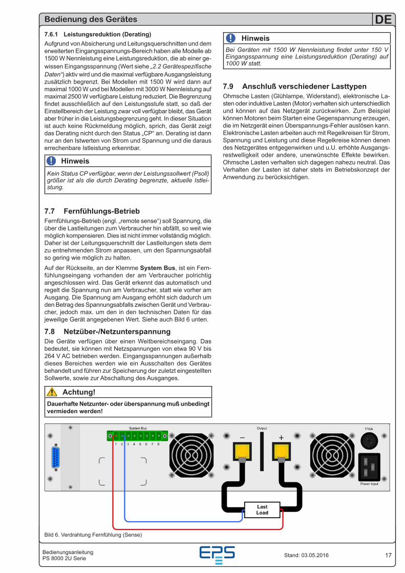
7.7 Fernfühlungs-BetriebFernfühlungs-Betrieb (engl. „remote sense“) soll Spannung, die über die Lastleitungen zum Verbraucher hin abfällt, so weit wie möglich kompensieren. Dies ist nicht immer vollständig möglich. Daher ist der Leitungsquerschnitt der Lastleitungen stets dem zu entnehmenden Strom anpassen, um den Spannungsabfall so gering wie möglich zu halten.
Auf der Rückseite, an der Klemme System Bus, ist ein Fern-fühlungseingang vorhanden der am Verbraucher polrichtig angeschlossen wird. Das Gerät erkennt das automatisch und regelt die Spannung nun am Verbraucher, statt wie vorher am Ausgang. Die Spannung am Ausgang erhöht sich dadurch um den Betrag des Spannungsabfalls zwischen Gerät und Verbrau-cher, jedoch max. um den in den technischen Daten für das jeweilige Gerät angegebenen Wert. Siehe auch Bild 6 unten.
7.8 Netzüber-/NetzunterspannungDie Geräte verfügen über einen Weitbereichseingang. Das bedeutet, sie können mit Netzspannungen von etwa 90 V bis 264 V AC betrieben werden. Eingangsspannungen außerhalb dieses Bereiches werden wie ein Ausschalten des Gerätes behandelt und führen zur Speicherung der zuletzt eingestellten Sollwerte, sowie zur Abschaltung des Ausganges.
Achtung!Dauerhafte Netzunter- oder überspannung muß unbedingt vermieden werden!
Bild 6. Verdrahtung Fernfühlung (Sense)
HinweisBei Geräten mit 1500 W Nennleistung findet unter 150 V Eingangsspannung eine Leistungsreduktion (Derating) auf 1000 W statt.
7.9 Anschluß verschiedener LasttypenOhmsche Lasten (Glühlampe, Widerstand), elektronische La-sten oder induktive Lasten (Motor) verhalten sich unterschiedlich und können auf das Netzgerät zurückwirken. Zum Beispiel können Motoren beim Starten eine Gegenspannung erzeugen, die im Netzgerät einen Überspannungs-Fehler auslösen kann. Elektronische Lasten arbeiten auch mit Regelkreisen für Strom, Spannung und Leistung und diese Regelkreise können denen des Netzgerätes entgegenwirken und u.U. erhöhte Ausgangs-restwelligkeit oder andere, unerwünschte Effekte bewirken. Ohmsche Lasten verhalten sich dagegen nahezu neutral. Das Verhalten der Lasten ist daher stets im Betriebskonzept der Anwendung zu berücksichtigen.
18
DE
BedienungsanleitungPS 8000 2U SerieStand: 03.05.2016
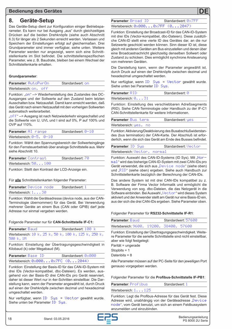
Parameter: Broad ID Standardwert: 0x7FFWertebereich: 0x000...0x7FF (0...2047)
Funktion: Einstellung der Broadcast-ID für das CAN-ID-System mit drei IDs (Vector-kompatibel, dbc-Dateien). Diese zusätzli-che CAN-ID stellt eine vierte ID des Gerätes dar, an die nur Setzwerte geschickt werden können. Sinn dieser ID ist, diese gleich mit anderen Geräten am Bus einzustellen und denen über eine Broadcastnachricht gleichzeitig denselben Sollwert oder Zustand zu schicken. Dies ermöglicht synchrone Ansteuerung von mehreren Geräten.
Die Darstellung kann, wenn der Parameter angewählt ist, durch Druck auf einen der Drehknöpfe zwischen dezimal und hexadezimal umgeschaltet werden.
Nur verfügbar, wenn ID Sys = Vector gewählt wurde. Siehe unten bei Parameter ID Sys.
Parameter: RID Standardwert: 0Wertebereich: 0...31
Funktion: Einstellung des verschiebbaren Adreßsegments (RID). Siehe CAN-Terminologie oder Handbuch zu der IF-C1 CAN-Schnittstellenkarte für weitere Informationen.
Parameter: Bus term Standardwert: yesWertebereich: yes, no
Funktion: Aktivierung/Deaktivierung des Busabschlußwiderstan-des (bus termination) der CAN-Karte. Der Abschluß ist erfor-derlich, wenn die sich das Gerät am Ende des Busses befindet.
Parameter: ID Sys Standardwert: VectorWertebereich: Vector, normal
Funktion: Auswahl des CAN-ID-Systems (ID Sys). Mit „Nor-mal“ wird das bisherige CAN-ID-System mit zwei CAN-IDs pro Gerät verwendet, die sich aus „Device node“ (siehe oben) und „RID“ (siehe oben) ergeben. Siehe auch Handbuch zur Schnittstellenkarte bezüglich der Berechnung der CAN-IDs.
Das andere System ist mit drei CAN-IDs kompatibel zu z. B. Software der Firma Vector Informatik und ermöglicht die Verwendung von sog. dbc-Dateien, die das Netzgerät in die Software einbinden. Bei Auswahl „Vector“ wird dieses System aktiviert und der Anwender stellt am Gerät nur eine Basis-ID ein, aus der sich die drei CAN-IDs ergeben. Siehe Parameter oben.
Folgender Parameter für RS232-Schnittstelle IF-R1:
Parameter: Baud Standardwert: 57600
Wertebereich: 9600, 19200, 38400, 57600
Funktion: Einstellung der Übertragungsgeschwindigkeit. Weite-re Parameter für die serielle Schnittstelle sind nicht einstellbar, aber wie folgt festgelegt:Parität = ungeradeStopbits = 1Datenbits = 8
Alle Parameter müssen auf der PC-Seite für den jeweiligen Port genauso vorgegeben werden.
Folgender Parameter für die Profibus-Schnittstelle IF-PB1:
Parameter: Profibus Standardwert: 1
Wertebereich: 1...125
Funktion: Legt die Profibus-Adresse für das Gerät fest. Diese Adresse wird, unabhängig von der Geräteadresse „Device node“, vom Gerät benutzt, um sich an einem Feldbussystem anzumelden und einzubinden.
Bedienung des Gerätes
8. Geräte-SetupDas Geräte-Setup dient zur Konfiguration einiger Betriebspa-rameter. Es kann nur bei Ausgang „aus“ durch gleichzeitiges Drücken auf die beiden Drehknöpfe (siehe auch Abschnitt 6.3) für länger als 2 Sekunden erreicht werden. Verlassen und Speichern der Einstellungen erfolgt auf gleichermaßen. Drei Grundparameter sind immer verfügbar, siehe unten. Weitere Parameter werden nur angezeigt, wenn sich eine Schnitt-stellenkarte im Slot befindet. Die schnittstellenspezifischen Parameter, wie z. B. Baudrate, bleiben bei einem Wechsel der Schnittstellenkarte erhalten.
Grundparameter:
Parameter: AutoPwrOn Standardwert: onWertebereich: on, off
Funktion: „on“ --> Wiederherstellung des Zustandes des DC-Ausganges und der Sollwerte auf den Zustand beim letzten Ausschalten bzw. Netzausfall. Damit kann erreicht werden, daß das Gerät nach einem Netzausfall mit den vorherigen Sollwerten automatisch weiterarbeitet.„off“ --> Ausgang ist nach Netzwiederkehr eingeschaltet und die Sollwerte von U, UVL und I sind auf 0%, P auf 100% und OVP auf 110%.
Parameter: AI range Standardwert: 0-10Wertebereich: 0-5, 0-10
Funktion: Wählt den Spannungsbereich der Sollwerteingänge für den Fernsteuerbetrieb über analoge Schnittstelle aus. Mehr siehe Abschnitt 10.
Parameter: Contrast Standardwert: 70Wertebereich: 50...100
Funktion: Stellt den Kontrast der LCD-Anzeige ein.
Für alle Schnittstellenkarten folgender Parameter:
Parameter: Device node Standardwert: 1Wertebereich: 1...30
Funktion: Wählt die Geräteadresse (device node, aus der CAN-Terminologie übernommen) für das Gerät. Bei Verwendung mehrerer Geräte an einem Bus (CAN oder GPIB) darf jede Adresse nur einmal vergeben werden.
Folgende Parameter nur für CAN-Schnittstelle IF-C1:
Parameter: Baud Standardwert: 100 kWertebereich: 10 k, 25 k, 50 k, 100 k, 125 k, 250 k, 500 k, 1M
Funktion: Einstellung der Übertragungsgeschwindigkeit in Kilobaud (k) oder Megabaud (M).
Parameter: Base ID Standardwert: 0x000Wertebereich: 0x000...0x7FC (0...2044)
Funktion: Einstellung der Basis-ID für das CAN-ID-System mit drei IDs (Vector-kompatibel, dbc-Dateien). Es werden, aus-gehend von der Basis-ID drei CAN-IDs pro Gerät reserviert, daher ist dieser Wert nur in 4er-Schritten einstellbar. Die Dar-stellung kann, wenn der Parameter angewählt ist, durch Druck auf einen der Drehknöpfe zwischen dezimal und hexadezimal umgeschaltet werden.
Nur verfügbar, wenn ID Sys = Vector gewählt wurde. Siehe unten bei Parameter ID Sys.
19BedienungsanleitungPS 8000 2U Serie
DE
Stand: 03.05.2016
10. Die Analogschnittstelle10.1 AllgemeinesDie fest eingebaute, nicht galvanische getrennte, 15-polige analoge Schnittstelle (AS) befindet sich auf der Rückseite des Gerätes und bietet unter Anderem folgende Möglichkeiten:
• Fernsteuerung von Strom und Spannung
• Fernsteuerung von Leistung (bei Geräten ab 1 kW)
• Fernüberwachung des Status (OT, OVP, CC, CV)
• Fernüberwachung der Istwerte
• Ferngesteuertes Ein/Aus des Ausganges
Über die analoge Schnittstelle können Strom, Spannung und Leistung gestellt werden. Dies geschieht immer gleichzeitig. Das heißt, man kann nicht Spannung über die AS vorgeben und Strom und Leistung am Gerät mittels Drehknopf einstellen oder umgekehrt. Geräte unter 1 kW Ausgangsleistung haben keine einstellbare Leistung und somit ist der Sollwerteingang PSEL nicht wirksam und muß nicht vorgegeben werden.
Der OVP-Sollwert kann über analog nicht gestellt werden und ist daher am Gerät einzustellen. Ein Umschalten auf Preset-Anzeige zeigt auf den Anzeigen die analog vorgegebenen Sollwerte an. Die analogen Sollwerte können eine externe Spannung eingespeist oder durch am Pin 3 ausgegebene Referenzspannung erzeugt werden.
Die AS kann mit den gängigen Spannungsbereichen 0...5 V oder 0...10 V für jeweils 0...100% Nennwert betrieben werden. Die Wahl des Spannungsbereiches findet im Geräte-Setup statt, siehe Abschnitt „8. Geräte-Setup“. Die am Pin 3 herausgege-bene Referenzspannung wird dabei angepaßt und ist dann, je nach Wahl, 5 V oder 10 V.
Es gilt dann folgendes:
0-5 V: Referenzspannung = 5 V, 0...5 V Sollwert entsprechen 0...100% Nennwert, 0...100% Istwert ensprechen 0...5 V an den Istwertausgängen (CMON, VMON).
0-10 V: Referenzspannung = 10 V, 0...10 V Sollwert entsprechen 0...100% Nennwert, 0...100% Istwert ensprechen 0...10 V and den Istwertausgängen (CMON, VMON).
Vorgabe von zu hohen Sollwerten (z. B. >5 V im gewählten 5 V-Bereich) wird abgefangen, in dem der jeweilige Sollwert auf 100% bleibt.Hinweise zur Benutzung:
• Steuern des Gerätes mit externen Sollwerten erfordert die Umschaltung auf Fernsteuerbetrieb mit Pin „REMOTE“ (5).
• Bevor die Hardware, welche die analoge Schnittstelle bedie-nen soll, verbunden wird, sind alle erforderlichen Leitungen zu legen und die Hardware zu prüfen, daß diese keine Span-nungen >12 V erzeugen kann.
• Der Eingang Rem-SB (Remote Standby, Pin 13) überlagert die Taste Output On. Das heißt, das Gerät kann nicht mit der Taste eingeschaltet werden, wenn der Pin das Signal „aus“ vorgibt, es sein denn, LOCAL-Modus ist aktiv. Dieser sperrt alle Schnittstellen vor Zugriff auf das Gerät. Siehe auch „6.2.7 Taste Local“.
• Die Massen der AS sind bezogen auf Minus Ausgang.
Schnittstellen
9. Digitale SchnittstellenkartenDas Gerät unterstützt folgende Schnittstellenkarten:IF-U1 (USB)IF-R1 (RS232)IF-C1 (CAN)IF-G1 (GPIB/IEEE)IF-E1 / IF-E1B (Ethernet/LAN + USB)IF-PB1 (Profibus + USB)Die Schnittstellenkarten benötigen nur wenige oder keine Einstellungen für den Betrieb. Die kartenspezifischen Einstel-lungen werden dauerhaft gespeichert und müssen bei erneuter Benutzung nach Kartenwechsel nicht neu konfiguriert werden. Details über die technischen Gegebenheiten und Handhabung der Schnittstellenkarten, sowie Anleitung zur Einbindung in eige-ne Applikationen (auch LabView) sind im Schnittstellenkarten-Handbuch zu finden.
Achtung!Einsetzen oder Entfernen der Schnittstellenkarte nur im ausgeschalteten Zustand (Netzschalter)!
Für die Konfiguration der Schnittstelle und deren Übertragungs-parameter siehe Abschnitt „8. Geräte-Setup“.
Über die digitale Schnittstellen können Strom-, Spannungs- und Leistungssollwert, sowie UVL und OVP gesetzt werden. Bei Wechsel auf Fernsteuerung werden die zuletzt am Gerät eingestellten Werte beibehalten, bis sie geändert werden. So-mit wäre eine reine Spannungssteuerung durch Vorgabe von Spannungssollwerten möglich, wenn die anderen Sollwerte unverändert blieben.
Sollwerte, die über die digitale Schnittstellen (außer GPIB) vorgegeben werden, sind immer Prozentwerte und entsprechen bei 100% (hex: 0x6400) bzw. bei 110% (hex: 0x6E00) beim OVP-Wert den Nennwerten des Gerätes. Bei GPIB werden Sollwerte immer als reale Werte vorgegeben.
Über die digitale Schnittstelle können viele weitere Funktionen des Gerätes gesteuert bzw. Werte gesetzt oder abgefragt werden. Mehr Information sind im Handbuch zu den Schnitt-stellenkarten zu finden.
20
DE
BedienungsanleitungPS 8000 2U SerieStand: 03.05.2016
Schnittstellen
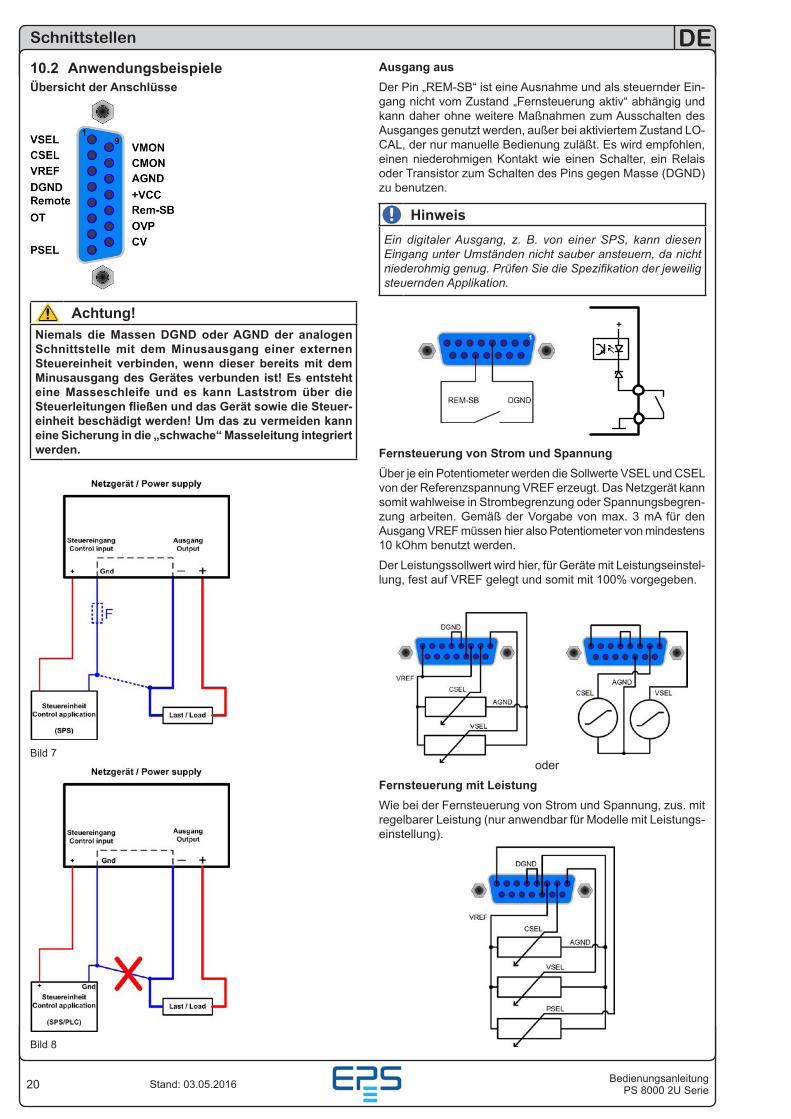
Ausgang ausDer Pin „REM-SB“ ist eine Ausnahme und als steuernder Ein-gang nicht vom Zustand „Fernsteuerung aktiv“ abhängig und kann daher ohne weitere Maßnahmen zum Ausschalten des Ausganges genutzt werden, außer bei aktiviertem Zustand LO-CAL, der nur manuelle Bedienung zuläßt. Es wird empfohlen, einen niederohmigen Kontakt wie einen Schalter, ein Relais oder Transistor zum Schalten des Pins gegen Masse (DGND) zu benutzen.
HinweisEin digitaler Ausgang, z. B. von einer SPS, kann diesen Eingang unter Umständen nicht sauber ansteuern, da nicht niederohmig genug. Prüfen Sie die Spezifikation der jeweilig steuernden Applikation.
+
Fernsteuerung von Strom und SpannungÜber je ein Potentiometer werden die Sollwerte VSEL und CSEL von der Referenzspannung VREF erzeugt. Das Netzgerät kann somit wahlweise in Strombegrenzung oder Spannungsbegren-zung arbeiten. Gemäß der Vorgabe von max. 3 mA für den Ausgang VREF müssen hier also Potentiometer von mindestens 10 kOhm benutzt werden.
Der Leistungssollwert wird hier, für Geräte mit Leistungseinstel-lung, fest auf VREF gelegt und somit mit 100% vorgegeben.
oder
Fernsteuerung mit LeistungWie bei der Fernsteuerung von Strom und Spannung, zus. mit regelbarer Leistung (nur anwendbar für Modelle mit Leistungs-einstellung).
10.2 AnwendungsbeispieleÜbersicht der Anschlüsse
Achtung!Niemals die Massen DGND oder AGND der analogen Schnittstelle mit dem Minusausgang einer externen Steuereinheit verbinden, wenn dieser bereits mit dem Minusausgang des Gerätes verbunden ist! Es entsteht eine Masseschleife und es kann Laststrom über die Steuerleitungen fließen und das Gerät sowie die Steuer-einheit beschädigt werden! Um das zu vermeiden kann eine Sicherung in die „schwache“ Masseleitung integriert werden.
Bild 7
Bild 8
21BedienungsanleitungPS 8000 2U Serie
DE
Stand: 03.05.2016
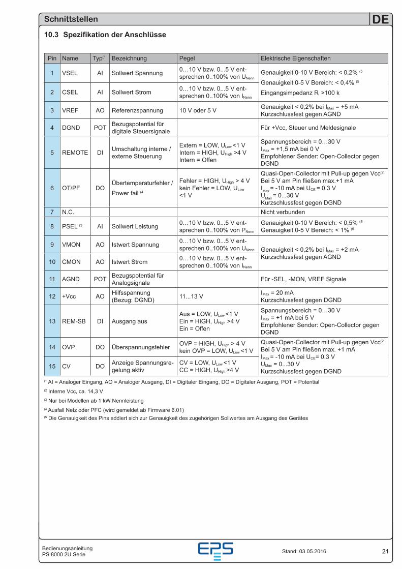
10.3 Spezifikation der Anschlüsse
Pin Name Typ(1 Bezeichnung Pegel Elektrische Eigenschaften
1 VSEL AI Sollwert Spannung 0…10 V bzw. 0...5 V ent-sprechen 0..100% von UNenn
Genauigkeit 0-10 V Bereich: < 0,2% (5
Genauigkeit 0-5 V Bereich: < 0,4% (5
Eingangsimpedanz Ri >100 k2 CSEL AI Sollwert Strom 0…10 V bzw. 0...5 V ent-sprechen 0..100% von INenn
3 VREF AO Referenzspannung 10 V oder 5 V Genauigkeit < 0,2% bei IMax = +5 mA Kurzschlussfest gegen AGND
4 DGND POT Bezugspotential für digitale Steuersignale Für +Vcc, Steuer und Meldesignale
5 REMOTE DI Umschaltung interne / externe Steuerung
Extern = LOW, ULow <1 V Intern = HIGH, UHigh >4 V Intern = Offen
Spannungsbereich = 0…30 V IMax = +1,5 mA bei 0 V Empfohlener Sender: Open-Collector gegen DGND
6 OT/PF DOÜbertemperaturfehler /
Power fail (4
Fehler = HIGH, UHigh > 4 V kein Fehler = LOW, ULow <1 V
Quasi-Open-Collector mit Pull-up gegen Vcc(2 Bei 5 V am Pin fließen max.+1 mA IMax = -10 mA bei UCE = 0.3 V UMax = 0...30 V Kurzschlussfest gegen DGND
7 N.C. Nicht verbunden
8 PSEL (3 AI Sollwert Leistung 0…10 V bzw. 0...5 V ent-sprechen 0..100% von PNenn
Genauigkeit 0-10 V Bereich: < 0,5% (5
Genauigkeit 0-5 V Bereich: < 1% (5
9 VMON AO Istwert Spannung 0…10 V bzw. 0...5 V ent-sprechen 0..100% von UNenn Genauigkeit < 0,2% bei IMax = +2 mA
Kurzschlussfest gegen AGND10 CMON AO Istwert Strom 0…10 V bzw. 0...5 V ent-
sprechen 0..100% von INenn
11 AGND POT Bezugspotential für Analogsignale Für -SEL, -MON, VREF Signale
12 +Vcc AO Hilfsspannung (Bezug: DGND) 11...13 V IMax = 20 mA
Kurzschlussfest gegen DGND
13 REM-SB DI Ausgang ausAus = LOW, ULow <1 V Ein = HIGH, UHigh >4 V Ein = Offen
Spannungsbereich = 0…30 V IMax = +1 mA bei 5 V Empfohlener Sender: Open-Collector gegen DGND
14 OVP DO Überspannungsfehler OVP = HIGH, UHigh > 4 V kein OVP = LOW, ULow <1 V
Quasi-Open-Collector mit Pull-up gegen Vcc(2 Bei 5 V am Pin fließen max. +1 mA IMax = -10 mA bei UCE= 0,3 V UMax = 0...30 V Kurzschlussfest gegen DGND
15 CV DO Anzeige Spannungsre-gelung aktiv
CV = LOW, ULow <1 V CC = HIGH, UHigh >4 V
(1 AI = Analoger Eingang, AO = Analoger Ausgang, DI = Digitaler Eingang, DO = Digitaler Ausgang, POT = Potential(2 Interne Vcc, ca. 14,3 V(3 Nur bei Modellen ab 1 kW Nennleistung(4 Ausfall Netz oder PFC (wird gemeldet ab Firmware 6.01)(5 Die Genauigkeit des Pins addiert sich zur Genauigkeit des zugehörigen Sollwertes am Ausgang des Gerätes
Schnittstellen
22
DE
BedienungsanleitungPS 8000 2U SerieStand: 03.05.2016
Verschiedenes
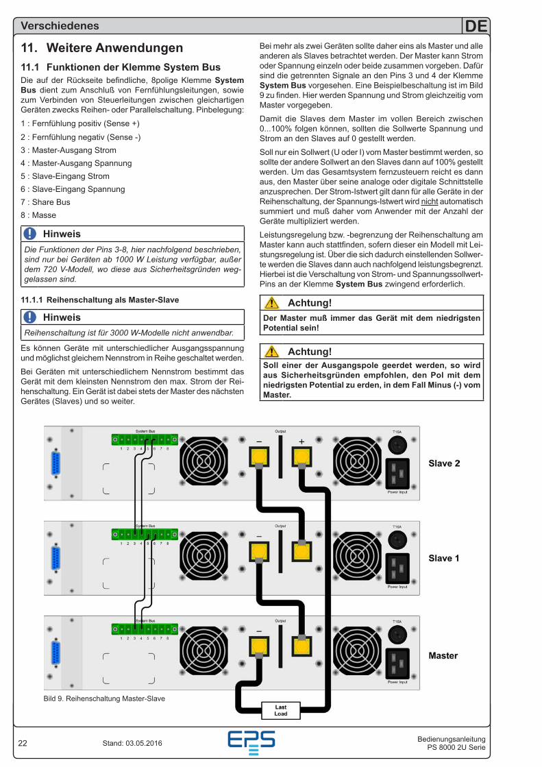
11. Weitere Anwendungen11.1 Funktionen der Klemme System BusDie auf der Rückseite befindliche, 8polige Klemme System Bus dient zum Anschluß von Fernfühlungsleitungen, sowie zum Verbinden von Steuerleitungen zwischen gleichartigen Geräten zwecks Reihen- oder Parallelschaltung. Pinbelegung:
1 : Fernfühlung positiv (Sense +)
2 : Fernfühlung negativ (Sense -)3 : Master-Ausgang Strom4 : Master-Ausgang Spannung5 : Slave-Eingang Strom6 : Slave-Eingang Spannung7 : Share Bus8 : Masse
HinweisDie Funktionen der Pins 3-8, hier nachfolgend beschrieben, sind nur bei Geräten ab 1000 W Leistung verfügbar, außer dem 720 V-Modell, wo diese aus Sicherheitsgründen weg-gelassen sind.
11.1.1 Reihenschaltung als Master-Slave
HinweisReihenschaltung ist für 3000 W-Modelle nicht anwendbar.
Es können Geräte mit unterschiedlicher Ausgangsspannung und möglichst gleichem Nennstrom in Reihe geschaltet werden.
Bei Geräten mit unterschiedlichem Nennstrom bestimmt das Gerät mit dem kleinsten Nennstrom den max. Strom der Rei-henschaltung. Ein Gerät ist dabei stets der Master des nächsten Gerätes (Slaves) und so weiter.
Bei mehr als zwei Geräten sollte daher eins als Master und alle anderen als Slaves betrachtet werden. Der Master kann Strom oder Spannung einzeln oder beide zusammen vorgeben. Dafür sind die getrennten Signale an den Pins 3 und 4 der Klemme System Bus vorgesehen. Eine Beispielbeschaltung ist im Bild 9 zu finden. Hier werden Spannung und Strom gleichzeitig vom Master vorgegeben.
Damit die Slaves dem Master im vollen Bereich zwischen 0...100% folgen können, sollten die Sollwerte Spannung und Strom an den Slaves auf 0 gestellt werden.
Soll nur ein Sollwert (U oder I) vom Master bestimmt werden, so sollte der andere Sollwert an den Slaves dann auf 100% gestellt werden. Um das Gesamtsystem fernzusteuern reicht es dann aus, den Master über seine analoge oder digitale Schnittstelle anzusprechen. Der Strom-Istwert gilt dann für alle Geräte in der Reihenschaltung, der Spannungs-Istwert wird nicht automatisch summiert und muß daher vom Anwender mit der Anzahl der Geräte multipliziert werden.
Leistungsregelung bzw. -begrenzung der Reihenschaltung am Master kann auch stattfinden, sofern dieser ein Modell mit Lei-stungsregelung ist. Über die sich dadurch einstellenden Sollwer-te werden die Slaves dann auch nachfolgend leistungsbegrenzt. Hierbei ist die Verschaltung von Strom- und Spannungssollwert-Pins an der Klemme System Bus zwingend erforderlich.
Achtung!Der Master muß immer das Gerät mit dem niedrigsten Potential sein!
Achtung!Soll einer der Ausgangspole geerdet werden, so wird aus Sicherheitsgründen empfohlen, den Pol mit dem niedrigsten Potential zu erden, in dem Fall Minus (-) vom Master.
Bild 9. Reihenschaltung Master-Slave
23BedienungsanleitungPS 8000 2U Serie
DE
Stand: 03.05.2016
Verschiedenes
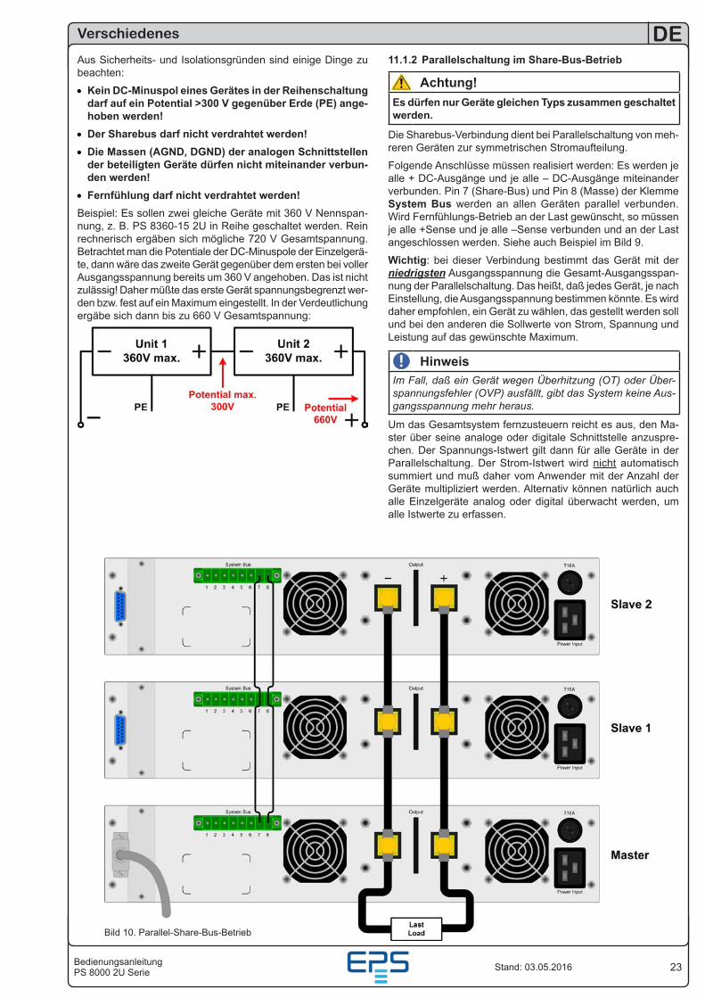
Aus Sicherheits- und Isolationsgründen sind einige Dinge zu beachten:
• Kein DC-Minuspol eines Gerätes in der Reihenschaltung darf auf ein Potential >300 V gegenüber Erde (PE) ange-hoben werden!
• Der Sharebus darf nicht verdrahtet werden!• Die Massen (AGND, DGND) der analogen Schnittstellen
der beteiligten Geräte dürfen nicht miteinander verbun-den werden!
• Fernfühlung darf nicht verdrahtet werden!Beispiel: Es sollen zwei gleiche Geräte mit 360 V Nennspan-nung, z. B. PS 8360-15 2U in Reihe geschaltet werden. Rein rechnerisch ergäben sich mögliche 720 V Gesamtspannung. Betrachtet man die Potentiale der DC-Minuspole der Einzelgerä-te, dann wäre das zweite Gerät gegenüber dem ersten bei voller Ausgangsspannung bereits um 360 V angehoben. Das ist nicht zulässig! Daher müßte das erste Gerät spannungsbegrenzt wer-den bzw. fest auf ein Maximum eingestellt. In der Verdeutlichung ergäbe sich dann bis zu 660 V Gesamtspannung:
Bild 10. Parallel-Share-Bus-Betrieb
11.1.2 Parallelschaltung im Share-Bus-Betrieb
Achtung!Es dürfen nur Geräte gleichen Typs zusammen geschaltet werden.
Die Sharebus-Verbindung dient bei Parallelschaltung von meh-reren Geräten zur symmetrischen Stromaufteilung.
Folgende Anschlüsse müssen realisiert werden: Es werden je alle + DC-Ausgänge und je alle – DC-Ausgänge miteinander verbunden. Pin 7 (Share-Bus) und Pin 8 (Masse) der Klemme System Bus werden an allen Geräten parallel verbunden. Wird Fernfühlungs-Betrieb an der Last gewünscht, so müssen je alle +Sense und je alle –Sense verbunden und an der Last angeschlossen werden. Siehe auch Beispiel im Bild 9.
Wichtig: bei dieser Verbindung bestimmt das Gerät mit der niedrigsten Ausgangsspannung die Gesamt-Ausgangsspan-nung der Parallelschaltung. Das heißt, daß jedes Gerät, je nach Einstellung, die Ausgangsspannung bestimmen könnte. Es wird daher empfohlen, ein Gerät zu wählen, das gestellt werden soll und bei den anderen die Sollwerte von Strom, Spannung und Leistung auf das gewünschte Maximum.
HinweisIm Fall, daß ein Gerät wegen Überhitzung (OT) oder Über-spannungsfehler (OVP) ausfällt, gibt das System keine Aus-gangsspannung mehr heraus.
Um das Gesamtsystem fernzusteuern reicht es aus, den Ma-ster über seine analoge oder digitale Schnittstelle anzuspre-chen. Der Spannungs-Istwert gilt dann für alle Geräte in der Parallelschaltung. Der Strom-Istwert wird nicht automatisch summiert und muß daher vom Anwender mit der Anzahl der Geräte multipliziert werden. Alternativ können natürlich auch alle Einzelgeräte analog oder digital überwacht werden, um alle Istwerte zu erfassen.
24
DE
BedienungsanleitungPS 8000 2U SerieStand: 03.05.2016
Verschiedenes
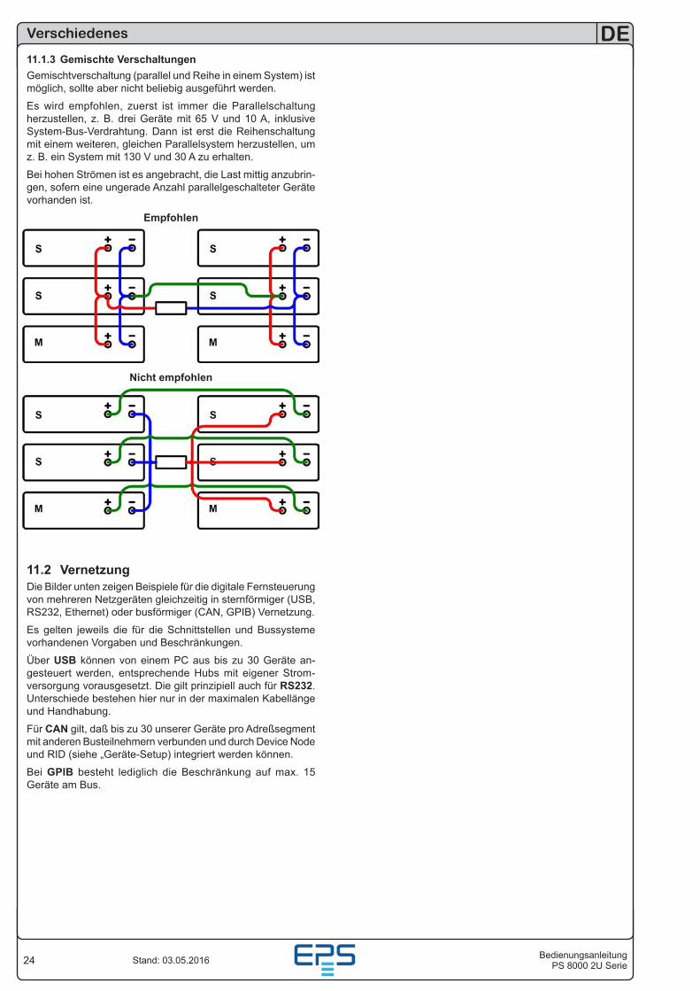
11.1.3 Gemischte VerschaltungenGemischtverschaltung (parallel und Reihe in einem System) ist möglich, sollte aber nicht beliebig ausgeführt werden.
Es wird empfohlen, zuerst ist immer die Parallelschaltung herzustellen, z. B. drei Geräte mit 65 V und 10 A, inklusive System-Bus-Verdrahtung. Dann ist erst die Reihenschaltung mit einem weiteren, gleichen Parallelsystem herzustellen, um z. B. ein System mit 130 V und 30 A zu erhalten.
Bei hohen Strömen ist es angebracht, die Last mittig anzubrin-gen, sofern eine ungerade Anzahl parallelgeschalteter Geräte vorhanden ist.
Empfohlen
Nicht empfohlen
11.2 VernetzungDie Bilder unten zeigen Beispiele für die digitale Fernsteuerung von mehreren Netzgeräten gleichzeitig in sternförmiger (USB, RS232, Ethernet) oder busförmiger (CAN, GPIB) Vernetzung.
Es gelten jeweils die für die Schnittstellen und Bussysteme vorhandenen Vorgaben und Beschränkungen.
Über USB können von einem PC aus bis zu 30 Geräte an-gesteuert werden, entsprechende Hubs mit eigener Strom-versorgung vorausgesetzt. Die gilt prinzipiell auch für RS232. Unterschiede bestehen hier nur in der maximalen Kabellänge und Handhabung.
Für CAN gilt, daß bis zu 30 unserer Geräte pro Adreßsegment mit anderen Busteilnehmern verbunden und durch Device Node und RID (siehe „Geräte-Setup) integriert werden können.
Bei GPIB besteht lediglich die Beschränkung auf max. 15 Geräte am Bus.
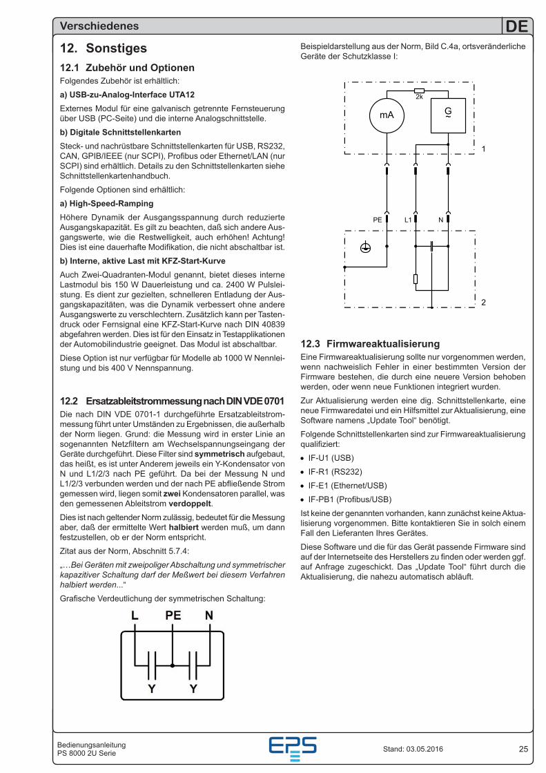
25BedienungsanleitungPS 8000 2U Serie
DE
Stand: 03.05.2016
Beispieldarstellung aus der Norm, Bild C.4a, ortsveränderliche Geräte der Schutzklasse I:
Datei : H:\dos\technik\Allgemeine Spezifikationen\andere\ersatzableitstrommessung.VSD
Ersatzableitstrommessung GrafikenHauptbild
Seite 1 von 1
Staberock
EA Diagramm
ThemaProjektleiterBearbeiter
Projekt
EA - ElektroAutomatik
Art. Nr.CAD Sys. MS-Visio
Netzeingang
N PE L
Y Y
1
mA G~
2k
PE L1 N
2
12.3 FirmwareaktualisierungEine Firmwareaktualisierung sollte nur vorgenommen werden, wenn nachweislich Fehler in einer bestimmten Version der Firmware bestehen, die durch eine neuere Version behoben werden, oder wenn neue Funktionen integriert wurden.
Zur Aktualisierung werden eine dig. Schnittstellenkarte, eine neue Firmwaredatei und ein Hilfsmittel zur Aktualisierung, eine Software namens „Update Tool“ benötigt.
Folgende Schnittstellenkarten sind zur Firmwareaktualisierung qualifiziert:
• IF-U1 (USB)
• IF-R1 (RS232)
• IF-E1 (Ethernet/USB)
• IF-PB1 (Profibus/USB)
Ist keine der genannten vorhanden, kann zunächst keine Aktua-lisierung vorgenommen. Bitte kontaktieren Sie in solch einem Fall den Lieferanten Ihres Gerätes.
Diese Software und die für das Gerät passende Firmware sind auf der Internetseite des Herstellers zu finden oder werden ggf. auf Anfrage zugeschickt. Das „Update Tool“ führt durch die Aktualisierung, die nahezu automatisch abläuft.
Verschiedenes
12. Sonstiges12.1 Zubehör und OptionenFolgendes Zubehör ist erhältlich:
a) USB-zu-Analog-Interface UTA12Externes Modul für eine galvanisch getrennte Fernsteuerung über USB (PC-Seite) und die interne Analogschnittstelle.
b) Digitale SchnittstellenkartenSteck- und nachrüstbare Schnittstellenkarten für USB, RS232, CAN, GPIB/IEEE (nur SCPI), Profibus oder Ethernet/LAN (nur SCPI) sind erhältlich. Details zu den Schnittstellenkarten siehe Schnittstellenkartenhandbuch.
Folgende Optionen sind erhältlich:
a) High-Speed-RampingHöhere Dynamik der Ausgangsspannung durch reduzierte Ausgangskapazität. Es gilt zu beachten, daß sich andere Aus-gangswerte, wie die Restwelligkeit, auch erhöhen! Achtung! Dies ist eine dauerhafte Modifikation, die nicht abschaltbar ist.
b) Interne, aktive Last mit KFZ-Start-KurveAuch Zwei-Quadranten-Modul genannt, bietet dieses interne Lastmodul bis 150 W Dauerleistung und ca. 2400 W Pulslei-stung. Es dient zur gezielten, schnelleren Entladung der Aus-gangskapazitäten, was die Dynamik verbessert ohne andere Ausgangswerte zu verschlechtern. Zusätzlich kann per Tasten-druck oder Fernsignal eine KFZ-Start-Kurve nach DIN 40839 abgefahren werden. Dies ist für den Einsatz in Testapplikationen der Automobilindustrie geeignet. Das Modul ist abschaltbar.
Diese Option ist nur verfügbar für Modelle ab 1000 W Nennlei-stung und bis 400 V Nennspannung.
12.2 Ersatzableitstrommessung nach DIN VDE 0701Die nach DIN VDE 0701-1 durchgeführte Ersatzableitstrom-messung führt unter Umständen zu Ergebnissen, die außerhalb der Norm liegen. Grund: die Messung wird in erster Linie an sogenannten Netzfiltern am Wechselspannungseingang der Geräte durchgeführt. Diese Filter sind symmetrisch aufgebaut, das heißt, es ist unter Anderem jeweils ein Y-Kondensator von N und L1/2/3 nach PE geführt. Da bei der Messung N und L1/2/3 verbunden werden und der nach PE abfließende Strom gemessen wird, liegen somit zwei Kondensatoren parallel, was den gemessenen Ableitstrom verdoppelt. Dies ist nach geltender Norm zulässig, bedeutet für die Messung aber, daß der ermittelte Wert halbiert werden muß, um dann festzustellen, ob er der Norm entspricht.
Zitat aus der Norm, Abschnitt 5.7.4:
„…Bei Geräten mit zweipoliger Abschaltung und symmetrischer kapazitiver Schaltung darf der Meßwert bei diesem Verfahren halbiert werden...“
Grafische Verdeutlichung der symmetrischen Schaltung:

27Instruction ManualPS 8000 2U Series
EN
Date: 05-03-2016
General
AboutEPS Stromversorgung GmbH
Alter Postweg 101
86159 Augsburg
Germany
Phone: 0821 / 570451-0
Web: www.eps-germany.de
© EPS
Reprint, duplication or partly, wrong use of this user instruction manual are prohibited and might be followed by legal conse-quences.
Danger to life!Hazardous voltageThe output voltage of some models can rise up to hazard-ous levels of >60 VDC!All live parts have to be covered. All actions at the output terminals have to be done while the unit is switched off from the mains (switch = OFF) and may only be executed by personnel which is instructed about the hazards of electrical current. Any connection between the load and the unit (at the output terminals) have to be scoop-proof. Applications connected to the power output must be configured and fused in a way that prevents the use of these to cause a damage or worse to the unit by overload or malfunction.
Caution!The DC output can still have hazardous voltage for a certain time after the output or the device has been switched off!
Keep in mind:• Only operate the device at a mains voltage as stipulated
on the type plate
• Never insert mechanical parts, especially from metal, through the air ventilation slots
• Avoid any use of liquids of any kind in the proximity of the device, they might get into it
• Do not connect voltage sources to the device which are able to generate voltages higher than the nominal voltage of the device
• In order to equip interface cards into the slot at the rear, the common ESD provisions have to be followed
• The interface card may only be plugged and unplugged while the unit is completely switched off (mains switch OFF)
• Aging of the device, as well heavy use may result in un-predictable behaviour of control elements like pushbuttons and rotary knobs.
• Do not connect external voltage sources with reversed polar-ity to the DC output! The device will be damaged.
• Avoid connecting external voltage sources to the DC output, especially those who can generate voltages higher than specified for the device!
28
EN
Instruction ManualPS 8000 2U SeriesDate: 05-03-2016
Table of contents
Page1. Introduction ..............................................................................................................................................................................292. Technical specifications ...........................................................................................................................................................29
2.1 Control panel and display ................................................................................................................................................292.2 Technical specifications ...................................................................................................................................................30
3. Device description ...................................................................................................................................................................333.1 Views ...............................................................................................................................................................................333.2 Scope of delivery .............................................................................................................................................................34
4. General ....................................................................................................................................................................................354.1 Prologue / Warning ..........................................................................................................................................................354.2 Cooling ............................................................................................................................................................................354.3 Maintenance / repair ........................................................................................................................................................35
5. Installation ...............................................................................................................................................................................355.1 Visual check ....................................................................................................................................................................355.2 Mains connection 2U models ..........................................................................................................................................355.3 Mains connection 4U models ..........................................................................................................................................355.4 DC output terminal...........................................................................................................................................................355.5 Terminal „Sense“ (Remote sense) ..................................................................................................................................355.6 Interface card slot ............................................................................................................................................................35
6. Handling ..................................................................................................................................................................................366.1 The display ......................................................................................................................................................................366.2 Pushbuttons on the control panel ....................................................................................................................................36
6.2.1 Pushbutton Preset Voltage .......................................................................................................................................366.2.2 Pushbutton Preset UVL / OVP ..................................................................................................................................376.2.3 Pushbutton Preset Power .........................................................................................................................................376.2.4 Pushbutton Preset Current .......................................................................................................................................376.2.5 Pushbutton Memory Select M1-M5 ..........................................................................................................................386.2.6 Pushbutton Memory Start / Memory Save >3 s ........................................................................................................386.2.7 Pushbutton Local ......................................................................................................................................................386.2.8 Pushbutton Lock / Unlock ........................................................................................................................................386.2.9 Pushbutton Output On / Output Off ..........................................................................................................................38
6.3 Other control elements ....................................................................................................................................................396.3.1 Rotary knobs.............................................................................................................................................................39
6.4 Adjusting set values.........................................................................................................................................................397. Device characteristics .............................................................................................................................................................40
7.1 Switching on by power switch..........................................................................................................................................407.2 Switching off by power switch ..........................................................................................................................................407.3 Switching to remote control .............................................................................................................................................407.4 Overvoltage alarms .........................................................................................................................................................407.5 Overtemperature alarms..................................................................................................................................................407.6 Voltage, current and power regulation .............................................................................................................................40
7.6.1 Power derating..........................................................................................................................................................417.7 Remote sense operation .................................................................................................................................................417.8 Mains undervoltage or overvoltage .................................................................................................................................417.9 Connecting different types of loads .................................................................................................................................41
8. Device setup ............................................................................................................................................................................429. Digital interface cards ..............................................................................................................................................................4310. Analogue interface ..................................................................................................................................................................43
10.1 General ............................................................................................................................................................................4310.2 Application examples.......................................................................................................................................................4410.3 Pin specification...............................................................................................................................................................45
11. Other applications ...................................................................................................................................................................4611.1 Functions of terminal System Bus ...................................................................................................................................46
11.1.1 Series connection in Master-Slave mode .................................................................................................................4611.1.2 Parallel connection ...................................................................................................................................................4711.1.3 Mixed connections ....................................................................................................................................................48
11.2 Networking.......................................................................................................................................................................4812. Miscellaneous ..........................................................................................................................................................................49
12.1 Accessories and options..................................................................................................................................................4912.2 Firmware update..............................................................................................................................................................49
29Instruction ManualPS 8000 2U Series
EN
Date: 05-03-2016
About the device
1. IntroductionThe laboratory power supplies of the series PS 8000 2U are ideally suited for test systems and industrial control facilities by their 19“ draw-out case.
Apart from standard functions of power supplies the user can define and recall 5 different presets of set values or make use of the integrated analogue interface, that can handle the common voltage ranges of 0...5 V or 0...10 V. This offers a way of easily monitoring the device as well as total remote control.
The optionally available, digital interface cards provide an even wider spectrum of control and monitoring functions by means of a PC.
Models from 1000 W feature an adjustable power regulation circuit (with two exceptions, see technical specs), as well as a „System Bus“ terminal which enables series connection as master-slave or parallel connection with share bus.
The integration into existent systems is done very comfortably by using an interface card, while there is no need to configure the card at all or with only a few settings.
Via the analogue interface, a power supply can als be operated in connection to other power supply units, controlling these via the interface. Or they can be controlled and monitored by an external control system, like a PLC.
The devices are microprocessor-controlled and thus delivers fast and accurate measurement and indication of actual values.
The main functions at a glance:
• Set voltage and current, each with 0...100%
• Adjustable overvoltage threshold 0...110% UNom
• Pluggable interface cards (CAN, USB, RS232, IEEE/GPIB, Ethernet/LAN, Profibus)
• Analogue interface for external control and monitoring with 0...5 V or 0...10 V (selectable) for 0...100%
• Power ratings of 640 W, 1000 W, 1500 W and 3000 W
• Temperature controlled fan
• Status indication (OT, OVP, CC, CV, CP)
• 5 selectable memory sets
• Series connection (models from 1 kW, except the 720 V model)
• Share-Bus for parallel operation (models from 1 kW)
• Vector™ compatible CAN system
• Free Windows software
• LabView™ VIs
2. Technical specifications2.1 Control panel and display
TypeDisplay: Dot matrix display 202 x 32 dots, separated into three areas
Knobs: 2 rotary knobs, 9+2 pushbuttons
Display formatsThe nominal values define the maximum adjustable range.
Actual values of voltage and current are displayed simultane-ously, the set values of the overvoltage threshold, the undervolt-age limit, voltage, current and power (models from 1 kW) are displayed separately.
Display of voltage valuesResolution: 4 digits Formats: 0.00 V...99.99 V 0.0 V...999.9 V
Display of current valuesResolution: 4 digits Formats: 0.000 A…9.999 A 0.00 A...99.9 A 0.0 A...999.9 A
Display of power values (models from 1 kW)Resolution: 4 digits Formats: 0.000 kW...9.999 kW
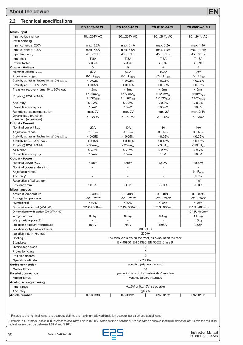
30
EN
Instruction ManualPS 8000 2U SeriesDate: 05-03-2016
About the device
2.2 Technical specificationsPS 8032-20 2U PS 8065-10 2U PS 8160-04 2U PS 8080-40 2U
Mains inputInput voltage range 90…264V AC 90…264V AC 90…264V AC 90…264V AC- with derating - - - -Input current at 230V max. 3.2A max. 3.4A max. 3.2A max. 4.8AInput current at 100V max. 7.5A max. 7.5A max. 7.5A max. 11.4AInput frequency 45…65Hz 45…65Hz 45…65Hz 45…65HzInput fuse T 8A T 8A T 8A T 16APower factor > 0.99 > 0.99 > 0.99 > 0.99
Output - Voltage 0 0 0 0Nominal voltage UNom 32V 65V 160V 80VAdjustable range 0V…UNom 0V…UNom 0V…UNom 0V…UNom
Stability at mains fluctuation ±10% ∆U IN < 0.02% < 0.02% < 0.02% < 0.02%Stability at 0…100% load < 0.05% < 0.05% < 0.05% < 0.05%Transient recovery time 10….90% load < 2ms < 2ms < 2ms < 2ms
Ripple @ BWL 20MHz< 100mVpp
< 8mVRMS
< 150mVpp
< 10mVRMS
< 120mVpp
< 20mVRMS
< 10mVpp
< 4mVRMS
Accuracy* ≤ 0.2% ≤ 0.2% ≤ 0.2% ≤ 0.2%Resolution of display 10mV 10mV 100mV 10mVRemote sense compensation max. 2V max. 2V max. 2V max. 2.5VOvervoltage protection threshold (adjustable) 0…35.2V 0…71.5V 0…176V 0….88V
Output - CurrentNominal current INom 20A 10A 4A 40AAdjustable range 0…INom 0…INom 0…INom 0…INom
Stability at mains fluctuation ±10% ∆U IN < 0.05% < 0.05% < 0.05% < 0.05%Stability at 0…100% ∆UOUT < 0.15% < 0.15% < 0.15% < 0.15%Ripple @ BWL 20MHz < 65mApp < 25mApp < 3mApp < 19mApp
Accuracy* ≤ 0.7% ≤ 0.7% ≤ 0.7% ≤ 0.2%Resolution of display 10mA 10mA 1mA 10mA
Output - PowerNominal power PNom 640W 650W 640W 1000WNominal power at derating - - - -Adjustable range - - - 0...PNom
Accuracy* - - - ≤ 1%Resolution of adjustment - - - 1WEfficiency max. 90.5% 91.0% 92.0% 93.0%
MiscellaneousAmbient temperature 0….40°C 0….40°C 0….40°C 0….40°CStorage temperature -20….70°C -20….70°C -20….70°C -20….70°CHumidity rel. < 80% < 80% < 80% < 80%Dimensions normal (WxHxD) 19" 2U 380mm 19" 2U 380mm 19" 2U 380mm 19" 2U 460mmDimensions with option ZH (WxHxD) - - - 19" 2U 460mmWeight normal 9.5kg 9.5kg 9.5kg 11.5kgWeight with option ZH - - - 13kgIsolation +output<->enclosure 500V 700V 1500V 950VIsolation -output<->enclosureIsolation input<->outputCoolingStandardsOvervoltage classProtection classPollution degreeOperation altitude
Series connectionMaster-Slave
Parallel connectionMaster-Slave
Analogue programmingInput rangeAccuracy
Article number 09230130 09230131 09230132 09230133
0…5V or 0…10V, selectable< 0.2%
noyes, with current distribution via Share bus
yes, via analog interface
12
< 2000mpossible (with restrictions)
2500Vby fans, air inlets on the front, air exhaust on the rear
EN 60950, EN 61326, EN 55022 Class B 2
300V DC
* Related to the nominal value, the accuracy defines the maximum allowed deviation between set value and actual value.
Example: a 80 V model has min. 0.2% voltage accuracy. This is 160 mV. When setting a voltage of 5 V and with an allowed maximum deviation of 160 mV, the resulting actual value could be between 4.84 V and 5.16 V.
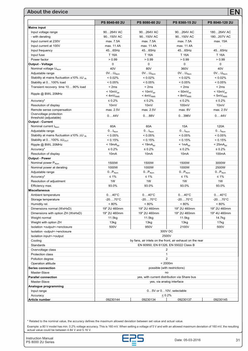
31Instruction ManualPS 8000 2U Series
EN
Date: 05-03-2016
About the device
PS 8040-60 2U PS 8080-60 2U PS 8360-15 2U PS 8040-120 2UMains input
Input voltage range 90…264V AC 90…264V AC 90…264V AC 180…264V AC- with derating 90...150V AC 90...150V AC 90...150V AC 180...207V ACInput current at 230V max. 7.5A max. 7.5A max. 7.5A max. 15AInput current at 100V max. 11.4A max. 11.4A max. 11.4A -Input frequency 45…65Hz 45…65Hz 45…65Hz 45…65HzInput fuse T 16A T 16A T 16A T 16APower factor > 0.99 > 0.99 > 0.99 > 0.99
Output - Voltage 0 0 0 0Nominal voltage UNom 40V 80V 360V 40VAdjustable range 0V…UNom 0V…UNom 0V…UNom 0V…UNom
Stability at mains fluctuation ±10% ∆U IN < 0.02% < 0.02% < 0.02% < 0.02%Stability at 0…100% load < 0.05% < 0.05% < 0.05% < 0.05%Transient recovery time 10….90% load < 2ms < 2ms < 2ms < 2ms
Ripple @ BWL 20MHz< 10mVpp
< 4mVRMS
< 10mVpp
< 4mVRMS
< 50mVpp
< 8mVRMS
< 10mVpp
< 5mVRMS
Accuracy* ≤ 0.2% ≤ 0.2% ≤ 0.2% ≤ 0.2%Resolution of display 10mV 10mV 100mV 10mVRemote sense compensation max. 2.5V max. 2.5V max. 8V max. 2.5VOvervoltage protection threshold (adjustable) 0….44V 0….88V 0…396V 0….44V
Output - CurrentNominal current INom 60A 60A 15A 120AAdjustable range 0…INom 0…INom 0…INom 0…INom
Stability at mains fluctuation ±10% ∆U IN < 0.05% < 0.05% < 0.05% < 0.05%Stability at 0…100% ∆UOUT < 0.15% < 0.15% < 0.15% < 0.15%Ripple @ BWL 20MHz < 19mApp < 19mApp < 1mApp < 25mApp
Accuracy* ≤ 0.2% ≤ 0.2% ≤ 0.2% ≤ 0.2%Resolution of display 10mA 10mA 10mA 100mA
Output - PowerNominal power PNom 1500W 1500W 1500W 3000WNominal power at derating 1000W 1000W 1000W 2500WAdjustable range 0...PNom 0...PNom 0...PNom 0...PNom
Accuracy* ≤ 1% ≤ 1% ≤ 1% ≤ 1%Resolution of adjustment 1W 1W 1W 1WEfficiency max. 93.0% 93.0% 93.0% 93.0%
MiscellaneousAmbient temperature 0….40°C 0….40°C 0….40°C 0….40°CStorage temperature -20….70°C -20….70°C -20….70°C -20….70°CHumidity rel. < 80% < 80% < 80% < 80%Dimensions normal (WxHxD) 19" 2U 460mm 19" 2U 460mm 19" 2U 460mm 19" 2U 460mmDimensions with option ZH (WxHxD) 19" 2U 460mm 19" 2U 460mm 19" 2U 460mm 19" 4U 460mmWeight normal 11.5kg 11.5kg 11.5kg 14.7kgWeight with option ZH 13kg 13kg 13kg 17kgIsolation +output<->enclosure 500V 950V 2100V 500VIsolation -output<->enclosureIsolation input<->outputCoolingStandardsOvervoltage classProtection classPollution degreeOperation altitude
Series connectionMaster-Slave
Parallel connectionMaster-Slave
Analogue programmingInput rangeAccuracy
Article number 09230144 09230134 09230137 09230145
by fans, air inlets on the front, air exhaust on the rearEN 60950, EN 61326, EN 55022 Class B
2
0…5V or 0…10V, selectable< 0.2%
noyes, with current distribution via Share bus
12
< 2000mpossible (with restrictions)
300V DC
yes, via analog interface
2500V
* Related to the nominal value, the accuracy defines the maximum allowed deviation between set value and actual value.
Example: a 80 V model has min. 0.2% voltage accuracy. This is 160 mV. When setting a voltage of 5 V and with an allowed maximum deviation of 160 mV, the resulting actual value could be between 4.84 V and 5.16 V.
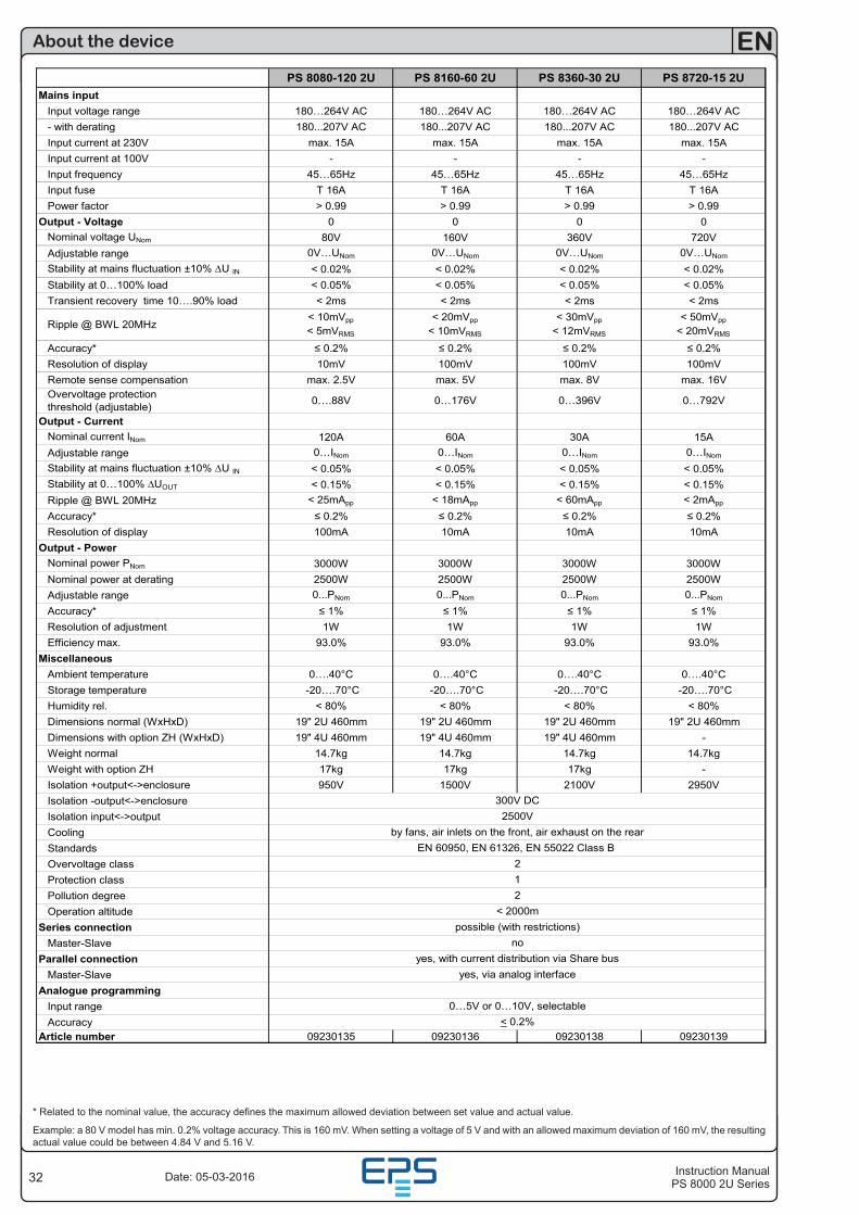
32
EN
Instruction ManualPS 8000 2U SeriesDate: 05-03-2016
About the device
PS 8080-120 2U PS 8160-60 2U PS 8360-30 2U PS 8720-15 2UMains input
Input voltage range 180…264V AC 180…264V AC 180…264V AC 180…264V AC- with derating 180...207V AC 180...207V AC 180...207V AC 180...207V ACInput current at 230V max. 15A max. 15A max. 15A max. 15AInput current at 100V - - - -Input frequency 45…65Hz 45…65Hz 45…65Hz 45…65HzInput fuse T 16A T 16A T 16A T 16APower factor > 0.99 > 0.99 > 0.99 > 0.99
Output - Voltage 0 0 0 0Nominal voltage UNom 80V 160V 360V 720VAdjustable range 0V…UNom 0V…UNom 0V…UNom 0V…UNom
Stability at mains fluctuation ±10% ∆U IN < 0.02% < 0.02% < 0.02% < 0.02%Stability at 0…100% load < 0.05% < 0.05% < 0.05% < 0.05%Transient recovery time 10….90% load < 2ms < 2ms < 2ms < 2ms
Ripple @ BWL 20MHz< 10mVpp
< 5mVRMS
< 20mVpp
< 10mVRMS
< 30mVpp
< 12mVRMS
< 50mVpp
< 20mVRMS
Accuracy* ≤ 0.2% ≤ 0.2% ≤ 0.2% ≤ 0.2%Resolution of display 10mV 100mV 100mV 100mVRemote sense compensation max. 2.5V max. 5V max. 8V max. 16VOvervoltage protection threshold (adjustable) 0….88V 0…176V 0…396V 0…792V
Output - CurrentNominal current INom 120A 60A 30A 15AAdjustable range 0…INom 0…INom 0…INom 0…INom
Stability at mains fluctuation ±10% ∆U IN < 0.05% < 0.05% < 0.05% < 0.05%Stability at 0…100% ∆UOUT < 0.15% < 0.15% < 0.15% < 0.15%Ripple @ BWL 20MHz < 25mApp < 18mApp < 60mApp < 2mApp
Accuracy* ≤ 0.2% ≤ 0.2% ≤ 0.2% ≤ 0.2%Resolution of display 100mA 10mA 10mA 10mA
Output - PowerNominal power PNom 3000W 3000W 3000W 3000WNominal power at derating 2500W 2500W 2500W 2500WAdjustable range 0...PNom 0...PNom 0...PNom 0...PNom
Accuracy* ≤ 1% ≤ 1% ≤ 1% ≤ 1%Resolution of adjustment 1W 1W 1W 1WEfficiency max. 93.0% 93.0% 93.0% 93.0%
MiscellaneousAmbient temperature 0….40°C 0….40°C 0….40°C 0….40°CStorage temperature -20….70°C -20….70°C -20….70°C -20….70°CHumidity rel. < 80% < 80% < 80% < 80%Dimensions normal (WxHxD) 19" 2U 460mm 19" 2U 460mm 19" 2U 460mm 19" 2U 460mmDimensions with option ZH (WxHxD) 19" 4U 460mm 19" 4U 460mm 19" 4U 460mm -Weight normal 14.7kg 14.7kg 14.7kg 14.7kgWeight with option ZH 17kg 17kg 17kg -Isolation +output<->enclosure 950V 1500V 2100V 2950VIsolation -output<->enclosureIsolation input<->outputCoolingStandardsOvervoltage classProtection classPollution degreeOperation altitude
Series connectionMaster-Slave
Parallel connectionMaster-Slave
Analogue programmingInput rangeAccuracy
Article number 09230135 09230136 09230138 09230139
< 2000m
300V DC
yes, via analog interface
12
EN 60950, EN 61326, EN 55022 Class B 2
possible (with restrictions)
2500Vby fans, air inlets on the front, air exhaust on the rear
0…5V or 0…10V, selectable< 0.2%
noyes, with current distribution via Share bus
* Related to the nominal value, the accuracy defines the maximum allowed deviation between set value and actual value.
Example: a 80 V model has min. 0.2% voltage accuracy. This is 160 mV. When setting a voltage of 5 V and with an allowed maximum deviation of 160 mV, the resulting actual value could be between 4.84 V and 5.16 V.
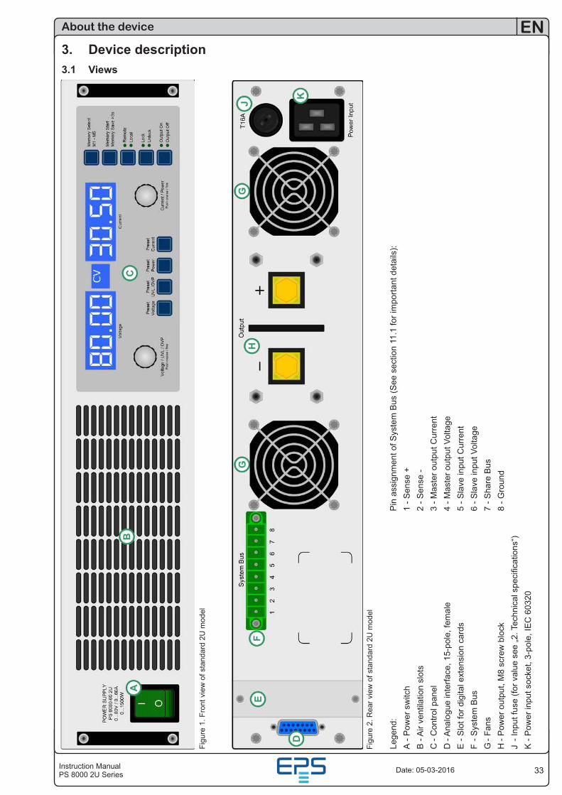
33Instruction ManualPS 8000 2U Series
EN
Date: 05-03-2016
About the device
3. Device description3.1 Views
Figu
re 1
. Fro
nt v
iew
of s
tand
ard
2U m
odel
Lege
nd:
P
in a
ssig
nmen
t of S
yste
m B
us (S
ee s
ectio
n 11
.1 fo
r im
porta
nt d
etai
ls):
A - P
ower
sw
itch
1
- Sen
se +
B -
Air
vent
ilatio
n sl
ots
2 - S
ense
-C
- C
ontro
l pan
el
3 - M
aste
r out
put C
urre
ntD
- A
nalo
gue
inte
rface
, 15-
pole
, fem
ale
4 - M
aste
r out
put V
olta
geE
- S
lot f
or d
igita
l ext
ensi
on c
ards
5 - S
lave
inpu
t Cur
rent
F - S
yste
m B
us
6
- Sla
ve in
put V
olta
geG
- Fa
ns
7
- Sha
re B
usH
- P
ower
out
put,
M8
scre
w b
lock
8 - G
roun
dJ
- Inp
ut fu
se (f
or v
alue
see
„2. T
echn
ical
spe
cific
atio
ns“)
K -
Pow
er in
put s
ocke
t, 3-
pole
, IE
C 6
0320
Figu
re 2
. Rea
r vie
w o
f sta
ndar
d 2U
mod
el
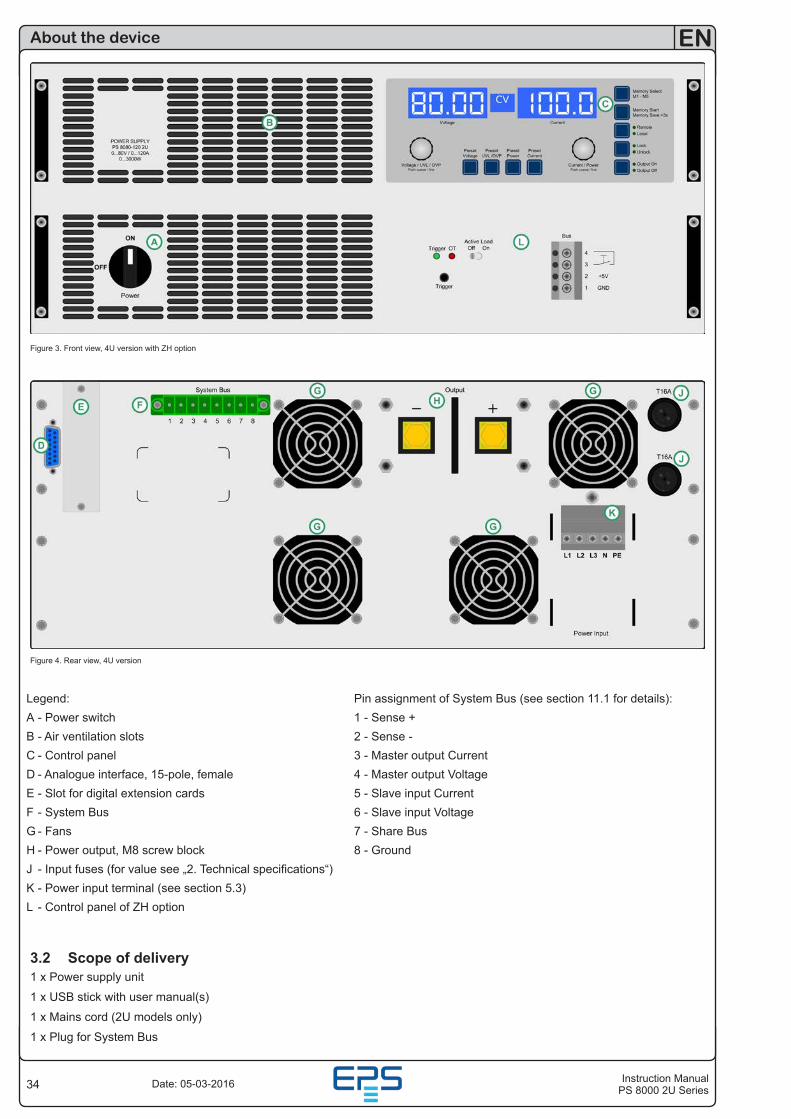
34
EN
Instruction ManualPS 8000 2U SeriesDate: 05-03-2016
About the device
Figure 3. Front view, 4U version with ZH option
Figure 4. Rear view, 4U version
Legend: Pin assignment of System Bus (see section 11.1 for details):A - Power switch 1 - Sense +B - Air ventilation slots 2 - Sense -C - Control panel 3 - Master output CurrentD - Analogue interface, 15-pole, female 4 - Master output VoltageE - Slot for digital extension cards 5 - Slave input CurrentF - System Bus 6 - Slave input VoltageG - Fans 7 - Share BusH - Power output, M8 screw block 8 - GroundJ - Input fuses (for value see „2. Technical specifications“)K - Power input terminal (see section 5.3)L - Control panel of ZH option
3.2 Scope of delivery1 x Power supply unit
1 x USB stick with user manual(s)
1 x Mains cord (2U models only)
1 x Plug for System Bus
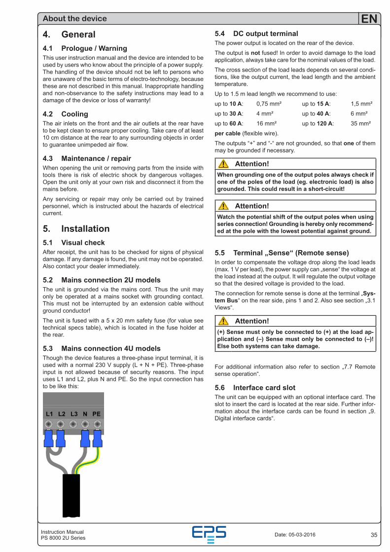
35Instruction ManualPS 8000 2U Series
EN
Date: 05-03-2016
5.4 DC output terminalThe power output is located on the rear of the device.
The output is not fused! In order to avoid damage to the load application, always take care for the nominal values of the load.
The cross section of the load leads depends on several condi-tions, like the output current, the lead length and the ambient temperature.
Up to 1.5 m lead length we recommend to use:
up to 10 A: 0,75 mm² up to 15 A: 1,5 mm²
up to 30 A: 4 mm² up to 40 A: 6 mm²
up to 60 A: 16 mm² up to 120 A: 35 mm²
per cable (flexible wire).
The outputs “+” and “-“ are not grounded, so that one of them may be grounded if necessary.
Attention!When grounding one of the output poles always check if one of the poles of the load (eg. electronic load) is also grounded. This could result in a short-circuit!
Attention!Watch the potential shift of the output poles when using series connection! Grounding is hereby only recommend-ed at the pole with the lowest potential against ground.
5.5 Terminal „Sense“ (Remote sense) In order to compensate the voltage drop along the load leads (max. 1 V per lead), the power supply can „sense“ the voltage at the load instead at the output. It will regulate the output voltage so that the desired voltage is provided to the load.
The connection for remote sense is done at the terminal „Sys-tem Bus“ on the rear side, pins 1 and 2. Also see section „3.1 Views“.
Attention!(+) Sense must only be connected to (+) at the load ap-plication and (–) Sense must only be connected to (–)! Else both systems can take damage.
For additional information also refer to section „7.7 Remote sense operation“.
5.6 Interface card slotThe unit can be equipped with an optional interface card. The slot to insert the card is located at the rear side. Further infor-mation about the interface cards can be found in section „9. Digital interface cards“.
About the device
4. General4.1 Prologue / WarningThis user instruction manual and the device are intended to be used by users who know about the principle of a power supply. The handling of the device should not be left to persons who are unaware of the basic terms of electro-technology, because these are not described in this manual. Inappropriate handling and non-observance to the safety instructions may lead to a damage of the device or loss of warranty!
4.2 CoolingThe air inlets on the front and the air outlets at the rear have to be kept clean to ensure proper cooling. Take care of at least 10 cm distance at the rear to any surrounding objects in order to guarantee unimpeded air flow.
4.3 Maintenance / repairWhen opening the unit or removing parts from the inside with tools there is risk of electric shock by dangerous voltages. Open the unit only at your own risk and disconnect it from the mains before.
Any servicing or repair may only be carried out by trained personnel, which is instructed about the hazards of electrical current.
5. Installation5.1 Visual checkAfter receipt, the unit has to be checked for signs of physical damage. If any damage is found, the unit may not be operated. Also contact your dealer immediately.
5.2 Mains connection 2U modelsThe unit is grounded via the mains cord. Thus the unit may only be operated at a mains socket with grounding contact. This must not be interrupted by an extension cable without ground conductor!
The unit is fused with a 5 x 20 mm safety fuse (for value see technical specs table), which is located in the fuse holder at the rear.
5.3 Mains connection 4U modelsThough the device features a three-phase input terminal, it is used with a normal 230 V supply (L + N + PE). Three-phase input is not allowed because of security reasons. The input uses L1 and L2, plus N and PE. So the input connection has to be like this:
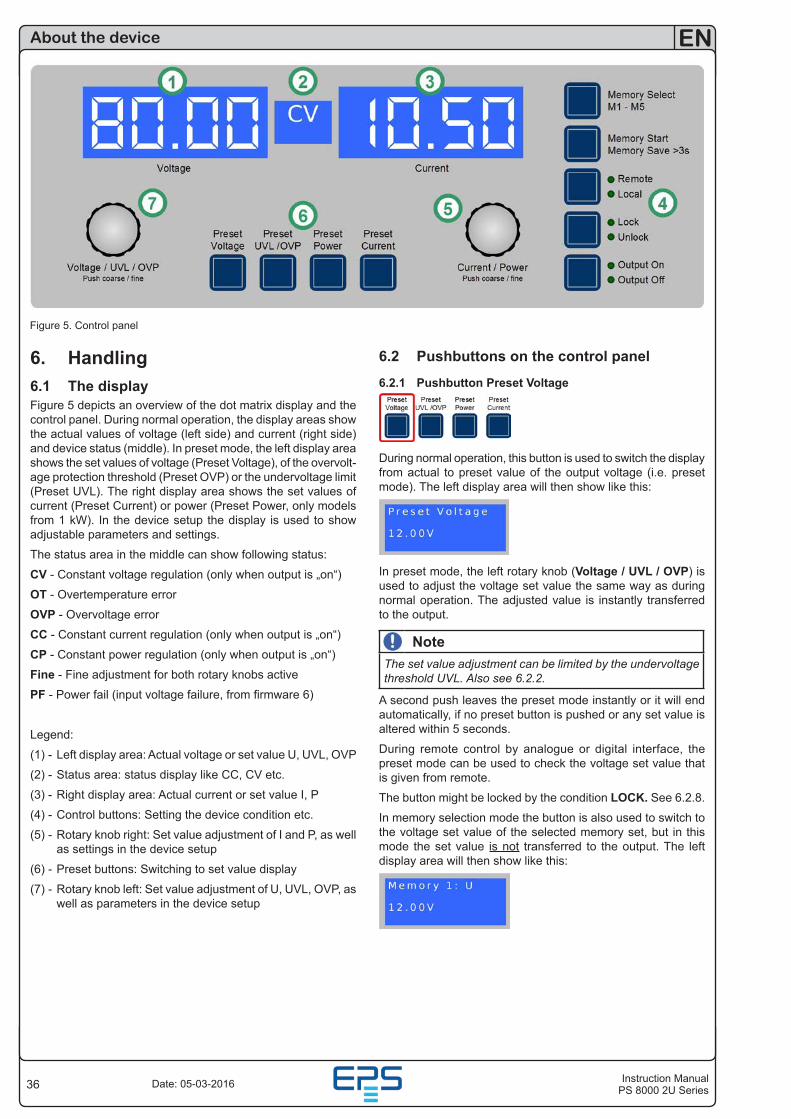
36
EN
Instruction ManualPS 8000 2U SeriesDate: 05-03-2016
6. Handling6.1 The displayFigure 5 depicts an overview of the dot matrix display and the control panel. During normal operation, the display areas show the actual values of voltage (left side) and current (right side) and device status (middle). In preset mode, the left display area shows the set values of voltage (Preset Voltage), of the overvolt-age protection threshold (Preset OVP) or the undervoltage limit (Preset UVL). The right display area shows the set values of current (Preset Current) or power (Preset Power, only models from 1 kW). In the device setup the display is used to show adjustable parameters and settings.
The status area in the middle can show following status:
CV - Constant voltage regulation (only when output is „on“)
OT - Overtemperature error
OVP - Overvoltage error
CC - Constant current regulation (only when output is „on“)
CP - Constant power regulation (only when output is „on“)
Fine - Fine adjustment for both rotary knobs active
PF - Power fail (input voltage failure, from firmware 6)
Legend:
(1) - Left display area: Actual voltage or set value U, UVL, OVP
(2) - Status area: status display like CC, CV etc.
(3) - Right display area: Actual current or set value I, P
(4) - Control buttons: Setting the device condition etc.
(5) - Rotary knob right: Set value adjustment of I and P, as well as settings in the device setup
(6) - Preset buttons: Switching to set value display
(7) - Rotary knob left: Set value adjustment of U, UVL, OVP, as well as parameters in the device setup
About the device
Figure 5. Control panel
6.2 Pushbuttons on the control panel
6.2.1 Pushbutton Preset Voltage
During normal operation, this button is used to switch the display from actual to preset value of the output voltage (i.e. preset mode). The left display area will then show like this:
In preset mode, the left rotary knob (Voltage / UVL / OVP) is used to adjust the voltage set value the same way as during normal operation. The adjusted value is instantly transferred to the output.
NoteThe set value adjustment can be limited by the undervoltage threshold UVL. Also see 6.2.2.
A second push leaves the preset mode instantly or it will end automatically, if no preset button is pushed or any set value is altered within 5 seconds.
During remote control by analogue or digital interface, the preset mode can be used to check the voltage set value that is given from remote.
The button might be locked by the condition LOCK. See 6.2.8.
In memory selection mode the button is also used to switch to the voltage set value of the selected memory set, but in this mode the set value is not transferred to the output. The left display area will then show like this:
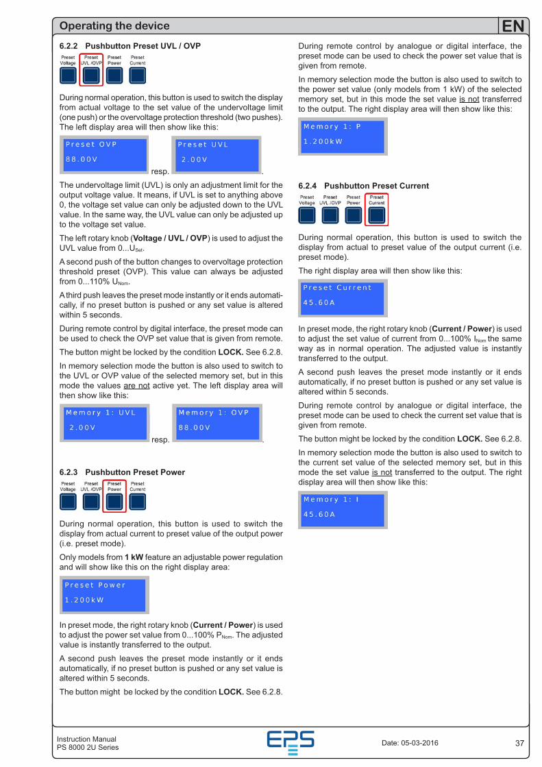
37Instruction ManualPS 8000 2U Series
EN
Date: 05-03-2016
6.2.2 Pushbutton Preset UVL / OVP
During normal operation, this button is used to switch the display from actual voltage to the set value of the undervoltage limit (one push) or the overvoltage protection threshold (two pushes). The left display area will then show like this:
resp. .
The undervoltage limit (UVL) is only an adjustment limit for the output voltage value. It means, if UVL is set to anything above 0, the voltage set value can only be adjusted down to the UVL value. In the same way, the UVL value can only be adjusted up to the voltage set value.
The left rotary knob (Voltage / UVL / OVP) is used to adjust the UVL value from 0...USet.
A second push of the button changes to overvoltage protection threshold preset (OVP). This value can always be adjusted from 0...110% UNom.
A third push leaves the preset mode instantly or it ends automati-cally, if no preset button is pushed or any set value is altered within 5 seconds.
During remote control by digital interface, the preset mode can be used to check the OVP set value that is given from remote.
The button might be locked by the condition LOCK. See 6.2.8.
In memory selection mode the button is also used to switch to the UVL or OVP value of the selected memory set, but in this mode the values are not active yet. The left display area will then show like this:
resp. .
6.2.3 Pushbutton Preset Power
During normal operation, this button is used to switch the display from actual current to preset value of the output power (i.e. preset mode).
Only models from 1 kW feature an adjustable power regulation and will show like this on the right display area:
In preset mode, the right rotary knob (Current / Power) is used to adjust the power set value from 0...100% PNom. The adjusted value is instantly transferred to the output.
A second push leaves the preset mode instantly or it ends automatically, if no preset button is pushed or any set value is altered within 5 seconds.
The button might be locked by the condition LOCK. See 6.2.8.
Operating the device
During remote control by analogue or digital interface, the preset mode can be used to check the power set value that is given from remote.
In memory selection mode the button is also used to switch to the power set value (only models from 1 kW) of the selected memory set, but in this mode the set value is not transferred to the output. The right display area will then show like this:
6.2.4 Pushbutton Preset Current
During normal operation, this button is used to switch the display from actual to preset value of the output current (i.e. preset mode).
The right display area will then show like this:
In preset mode, the right rotary knob (Current / Power) is used to adjust the set value of current from 0...100% INom the same way as in normal operation. The adjusted value is instantly transferred to the output.
A second push leaves the preset mode instantly or it ends automatically, if no preset button is pushed or any set value is altered within 5 seconds.
During remote control by analogue or digital interface, the preset mode can be used to check the current set value that is given from remote.
The button might be locked by the condition LOCK. See 6.2.8.
In memory selection mode the button is also used to switch to the current set value of the selected memory set, but in this mode the set value is not transferred to the output. The right display area will then show like this:
38
EN
Instruction ManualPS 8000 2U SeriesDate: 05-03-2016
6.2.5 Pushbutton Memory Select M1-M5
This button cycles through the 5 memory sets, each with set values for U, I and P, as well as UVL and OVP. From here, the selected memory set can be edited, stored or submitted. The button only works if the output is off. The memory mode and the selected memory set number are displayed like this:
Following options of use:
a) Adjust valuesOutput off, short push of the button, the display changes to the first memory set, as displayed above.
Now the set values of U (left) and I (right) of the selected memory set can be adjusted. The other adjustable values can be ac-cessed by pushing the corresponding preset buttons.
Further pushes will cycle through the memory sets up to number 5 and then exit memory mode.
The adjusted values remain as long the device is powered, but are not submitted to the output set values and are not saved yet! For saving see section 6.2.6.The button might be locked by the condition LOCK. See 6.2.8.
6.2.6 Pushbutton Memory Start / Memory Save >3 s
This pushbutton is either used to submit the values of the selected memory set to the output or to save the memory set. The button only works if the output is off.Following options of use:
b) Submit onlyOutput off, memory set is selected (1-5), button is pushed shortly --> the values of the memory set are submitted to the output and the memory mode exits. In order to use the new set values, the output is switched on as usual by button Output On or by remote control.
Note Submitting the values does not save them!
c) Save onlyOutput off, select memory set(s), adjust the values as desired, then push the button >3 s --> all memory sets are saved, but none is submitted to the output. The output remains off, the memory mode exits after saving.
The memory sets can also be defined by remote control and corresponding commands using a digital interface (except GPIB). They‘re stored immediately.
The button might be locked by the condition LOCK. See 6.2.8.
Operating the device
6.2.7 Pushbutton Local
This pushbutton activates or deactivate the LOCAL mode. In LOCAL mode, no remote control of the device is possible. LO-CAL mode is indicated by LED „Local“. As long as LOCAL is not active, the LED „Remote“ indicates an active remote control by analogue or digital interface.
The button might be locked by the condition LOCK. See 6.2.8.
NoteActivation of LOCAL mode results in immediate return from remote control (analogue or digital) and locks the device against further attempts to control it remotely, until LOCAL is cleared again.
NoteLOCAL condition is only temporary and will not be stored when switching the device off.
6.2.8 Pushbutton Lock / Unlock
This pushbutton activates or deactivates the control panel lock. The LOCK mode locks all buttons, except the LOCK button itself, and the rotary knobs against unintended operation.
NoteActivation of the LOCK mode instantly exits any preset or memory mode, if currently active. The display will return to normal display of actual values.
NoteSince firmware 6.02, LOCK mode will be stored when the device is switched off and restored after power-on.
6.2.9 Pushbutton Output On / Output Off
This pushbutton is used to manually switch the power output on or off, as long as the device is not in remote control mode. The output condition is always indicated by the LEDs „Output On“ or „Output Off“. If the output is switched on, the device indicates the currently active regulation mode CC, CV or CP (only models from 1 kW) in the status area in the middle of the display.
The button might be locked by the condition LOCK. See 6.2.8.
Switching the output on may be inhibited by pin 13 (REM-SB) of the analogue interface. See section „10. Analogue interface“.
The button also acknowledges the errors. See sections 7.4 and 7.5 fore more information.
39Instruction ManualPS 8000 2U Series
EN
Date: 05-03-2016
Operating the device
6.3 Other control elements
6.3.1 Rotary knobs
Both of the rotary knobs have a push button function. Pushing any or both of these will effect following:
a) Fine adjustment mode (Fine)A short push of any of both buttons activates or deactivates the fine adjustment mode for manual operation. If „Fine“ is active, all set values, thresholds and limits can be adjusted in smallest possible steps, no matter what mode is currently active (preset, memory etc.). It is indicated by the status text „Fine“ in the status area. Also see section „6.4 Adjusting set values“ below.
b) Device setupPushing both buttons together for >3 s while the output is off changes to device setup. It is left the same way.
6.4 Adjusting set values1. In manual operation
During manual operation, both rotary knobs are used to continu-ously adjust the set values of voltage and current from 0% to 100% nominal value in predefined steps (see table). In order to set the values for OVP and UVL the button Preset UVL/OVP has to pushed once or twice. In order to set the power set value (models from 1 kW only) the button Preset Power has to be pushed.
NoteThe OVP value can be lower than the voltage set value and will cause an OV error as soon as the output is switched on and the actual voltage reaches the OVP threshold!
Setting values manually can be done in fine or coarse steps, whereas coarse is default. Fine is required to be activated by the one of rotary knob pushbuttons and has a step width of 1.
For coarse adjustment, following step widths apply in depend-ency of the nominal values (also refer to technical specs):
Voltage / OVP / UVL CurrentNom. val. Coarse Fine Nom. val. Coarse Fine32 V 0.2 V 0.01 V 4 A 0.05 A 0.001 A40 V 0.25 V 0.01 V 10 A 0.1 A 0.01 A65 V 0.5 V 0.01 V 15 A 0.1 A 0.01 A80 V 0.5 V 0.01 V 20 A 0.2 A 0.01 A160 V 1 V 0.1 V 30 A 0.2 A 0.01 A360 V 2 V 0.1 V 40 A 0.5 A 0.01 A720 V 5 V 0.1 V 60 A 0.5 A 0.01 A
120 A 1 A 0.1 A
PowerNominal value Coarse Fine1000 W 0.01 kW 0.001 kW1500 W 0.01 kW 0.001 kW3000 W 0.02 kW 0.001 kW
NoteThe resolution of the set value adjustment in some cases is, depending on the nominal values, higher than the one of the output voltage. Thus it can happen that the output voltage only changes every 2 or 3 steps.
2. In remote control via analogue interfaceSee section „10. Analogue interface“.
3. In remote control via digital interface cardSee section „9. Digital interface cards“.
40
EN
Instruction ManualPS 8000 2U SeriesDate: 05-03-2016
Operating the device
7. Device characteristics7.1 Switching on by power switchThe power switch is located at the front. After switching on, the device will show some information in the display: manufacturer‘s name, address and logo, device type and firmware version. In the device setup (see section „8. Device setup“) there is an op-tion „AutoPwrOn“ (auto power-on) that determines the output condition after the device is switched on. Default is „on“ and means, that the set values of U, I, P, the values of OVP and UVL and the output condition are restored to what was present when the device was switched off the last time. In case the op-tion is set to „off“, the set values of U and I are set to 0, the set value of P to 100%, OVP to max., UVL to min. and the output is switched on after every start.
7.2 Switching off by power switchSwitching the device off by power switch is handled as mains blackout. The device will save the last set values and output condition. After a short time, power output and fans will be switched off and after a few seconds more, the device will be completely off.
7.3 Switching to remote controla) Analogue interface: Pin „Remote“ switches the device to remote control, if not inhibited by LOCAL mode or remote control by digital interface already being active. The set values pins VSEL, CSEL and PSEL (only required with models from 1 kW), as well as REM-SB are then in command. The output condition and the set values which are put into the pins are immediately set. After return from remote control, the output will be switched off.
b) Digital interface: Switching to remote control is done by the corresponding command (here: object), if not inhibited by LO-CAL mode or remote control via analogue interface already being active. I, keeps output state and set values until altered. Leaving remote control automatically switches the output off.
7.4 Overvoltage alarmsAn overvoltage alarm can occur due to an internal defect (out-put voltage rises uncontrollably) or by a too high voltage from external. The overvoltage protection (OVP) will switch off the output and indicate the alarm on the display by the status text „OV“ and on the pin „OVP“ of the analogue interface.
If the cause of the overvoltage is removed, the alarm has to be acknowledged first. In manual operation, it is done by pushing button Output On/Off, in analogue remote control with pin „REM-SB“ and in digital remote control by the corresponding command. Then status text „OV“ and OVP signal will disappear. If the alarm is still present, the output will not be switched on.
OV alarms are recorded into the internal alarm buffer. This buffer can be read out via a digital interface, except those using SCPI language. Reading the buffer will also acknowledge.
NoteThe status of an OV alarm has priority over the status of an OT alarm and will overwrite the status text „OT“ in case both alarms occur the same time and are not yet acknowledged.
7.5 Overtemperature alarmsAs soon as an overtemperature (OT) alarm occurs by internal overheating, the output is switched off and the status text „OT“ is indicated. Simultaneously, the LED „Output On“ will flash, indicating that the output will automatically switch on again as soon as the device has cooled down. In case this is not wanted, the output can be switched off manually. Then the LED stops flashing and the output won‘t switch on automatically.
If the output is off after the device has cooled down, it can be switched on again by using button Output On/Off or pin „REM-SB“ or the corresponding command. If the output is on, pushing button Output On/Off once or giving pin „REM-SB“ a high-to-low toggle or using the corresponding command first acknowledges the alarm and then switches the output off.
OT alarms are recorded into the internal alarm buffer. This buffer can be read out via a digital interface (except those using SCPI language). Reading the buffer will also acknowledge.
NoteThe status of an OT alarm has lower priority than an OV alarm and the status text „OT“ will be overwritten by „OV“ in case both alarms occur the same time and are not yet acknowledged.
7.6 Voltage, current and power regulationThe output voltage of the power supply and the resistance of the load determine the output current. If this current is lower than the current limitation set by the current set value, then the device is working in constant voltage (CV) regulation, indicated by the status text „CV“.
If the output current is limited by the current set value or by the nominal current, the device will change to constant current (CC) regulation mode, indicated by the status text „CC“.
Models from 1 kW output power additionally feature an adjust-able power limitation for 0...PNom. It becomes active and over-rides constant voltage or constant current regulation mode, if the product of actual current and actual voltage exceeds the adjusted power limitation or nominal power of the device. The power limitation primarily affects the output voltage. Because voltage, current and power limitation affect each other, various situations like these may occur:
Example 1: the device is in constant voltage regulation, then the power is limited down. As a result, the output voltage is de-creased. A lower output voltage results in a lower output current. In case the resistance of the load is then decreased, the output current will rise again and the output voltage will sink further.
Example 2: the device is in constant current regulation, the output voltage is defined by the resistance of the load. Then the power is limited down. Output voltage and current are decreasing to values according to the formula P = U * I. If the current set value is then decreased, the output current would also decrease and thus the output voltage. The product of both values, the actual power, would sink below the previously set power limit and the device would change from constant power regulation (CP) to constant current regulation (CC).
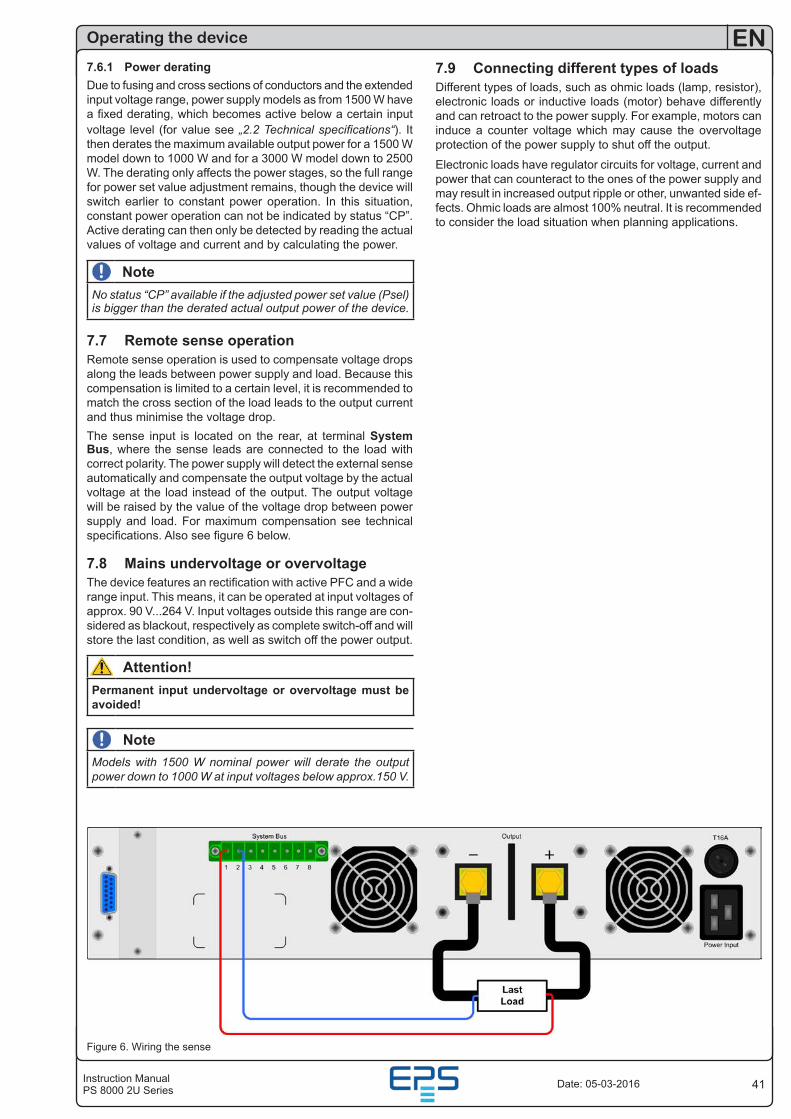
41Instruction ManualPS 8000 2U Series
EN
Date: 05-03-2016
Operating the device
7.6.1 Power deratingDue to fusing and cross sections of conductors and the extended input voltage range, power supply models as from 1500 W have a fixed derating, which becomes active below a certain input voltage level (for value see „2.2 Technical specifications“). It then derates the maximum available output power for a 1500 W model down to 1000 W and for a 3000 W model down to 2500 W. The derating only affects the power stages, so the full range for power set value adjustment remains, though the device will switch earlier to constant power operation. In this situation, constant power operation can not be indicated by status “CP”. Active derating can then only be detected by reading the actual values of voltage and current and by calculating the power.
NoteNo status “CP” available if the adjusted power set value (Psel) is bigger than the derated actual output power of the device.
7.7 Remote sense operationRemote sense operation is used to compensate voltage drops along the leads between power supply and load. Because this compensation is limited to a certain level, it is recommended to match the cross section of the load leads to the output current and thus minimise the voltage drop.The sense input is located on the rear, at terminal System Bus, where the sense leads are connected to the load with correct polarity. The power supply will detect the external sense automatically and compensate the output voltage by the actual voltage at the load instead of the output. The output voltage will be raised by the value of the voltage drop between power supply and load. For maximum compensation see technical specifications. Also see figure 6 below.
7.8 Mains undervoltage or overvoltageThe device features an rectification with active PFC and a wide range input. This means, it can be operated at input voltages of approx. 90 V...264 V. Input voltages outside this range are con-sidered as blackout, respectively as complete switch-off and will store the last condition, as well as switch off the power output.
Attention!Permanent input undervoltage or overvoltage must be avoided!
NoteModels with 1500 W nominal power will derate the output power down to 1000 W at input voltages below approx.150 V.
7.9 Connecting different types of loadsDifferent types of loads, such as ohmic loads (lamp, resistor), electronic loads or inductive loads (motor) behave differently and can retroact to the power supply. For example, motors can induce a counter voltage which may cause the overvoltage protection of the power supply to shut off the output.
Electronic loads have regulator circuits for voltage, current and power that can counteract to the ones of the power supply and may result in increased output ripple or other, unwanted side ef-fects. Ohmic loads are almost 100% neutral. It is recommended to consider the load situation when planning applications.
Figure 6. Wiring the sense
42
EN
Instruction ManualPS 8000 2U SeriesDate: 05-03-2016
8. Device setupThe device setup is intended to adjust certain operation param-eters. It can only be accessed while the output is off. Push both pushbuttons of the rotary knobs (also see section 6.3) simultane-ously for longer than 2 s. Leaving the setup and storage of the settings is done the same way. Three elementary settings are always available, see below. Other settings are only available if a digital interface card is equipped.
Elementary settings:
Parameter: AutoPwrOn Default: onSettings: on, off
Function: „on“ --> device restores the last output state and set values of last time the device was switched off or a blackout occurred. The purpose is to make the unit automatically continue operation after a blackout.„off“ --> the output is switched on and the set values of U, UVL and I are set to 0%, P to 100% and OVP to 110%, every time the unit is powered.
Parameter: AI range Default: 0-10Settings: 0-5, 0-10
Function: selects the control voltage range to use with the analogue interface. Further details in section 10.
Parameter: Contrast Default: 70Settings: 50...100
Adjusts the contrast of the LCD display.
For all interface cards this setting applies:
Parameter: Device node Default: 1Settings: 1...30
Function: Selects the device‘s address (i.e. device node, term taken from the CAN terminology). When using the device on a bus system (CAN or GPIB), every device must have a unique address!
Following settings only with CAN interface IF-C1:
Parameter: Baud Default: 100 kSettings: 10 k, 25 k, 50 k, 100 k, 125 k, 250 k, 500 k, 1M
Function: Selects the CAN transmission baud rate.
Parameter: Base ID Default: 0x000Settings: 0x000...0x7FC (0...2044)
Function: Defines the base ID (BAID) for the CAN ID system with three IDs (Vector compatible, dbc files). Three IDs are reserved for a device, based upon the adjusted base ID. Thus this values is only adjustable in steps of four. Display can be switched from decimal to hexadecimal by pushing any of the rotary knobs.
Only available, if ID Sys = Vector has been selected. See below at parameter ID Sys.
Operating the device
Parameter: Broad ID Default: 0x7FFSettings: 0x000...0x7FF (0...2047)
Function: Adjusts the broadcast ID (BCID) for the CAN ID sys-tem with three IDs (Vector compatible, dbc files). This extra ID is a fourth ID for the device which can be used for broadcast messages to multiple units on a bus. Purpose if this ID is to adjust it to the same value on all units that are targeted to be controlled simultaneously by set values or device conditions. Display can be switched from decimal to hexadecimal by push-ing any of the rotary knobs.
Only available, if ID Sys = Vector has been selected. See below at parameter ID Sys.
Parameter: RID Default: 0Settings: 0...31
Function: Selects the relocatable identifier segment (RID). Refer to CAN terminology or instruction manual of the IF-C1 CAN interface card for further information.
Parameter: Bus term Default: yesSettings: yes, no
Function: activates/deactivates the bus termination resistor of the CAN interface card. This is required if the device is at the end of the bus.
Parameter: ID Sys Default: VectorSettings: Vector, normal
Function: Selects the CAN ID system. With „Normal“, the former, old CAN ID system with two CAN IDs per unit is used, where the IDs are built from „Device node“ (see above) and „RID“ (see above) . Also see the external user manual for the in-terface cards regarding the calculation scheme of the CAN IDs.
The other ID system, selected with „Vector“, uses three CAN IDs per unit and it thus enables the use of so-called DBC files to implement the device into Vector company software. By select-ing this ID system, two ID related settings (see above) become active, where the user adjusts a base ID that defines the three CAN IDs, plus a broadcast ID (if used).
Following settings only with RS232 interface IF-R1:
Parameter: Baud Default: 57600
Settings: 9600, 19200, 38400, 57600
Function: Selects the serial transmission baud rate (in baud). Further parameters for the RS232 are not configurable, but defined as follows:
Parity = odd Stop bits = 1 Data bits = 8 and have to be set to the same configuration at the PC.
Following settings only with Profibus interface IF-PB1:
Parameter: Profibus Default: 1
Settings: 1-125
Function: Defines the Profibus address of the device. This address is used apart from the device node to implement and access the unit on a field bus system.
43Instruction ManualPS 8000 2U Series
EN
Date: 05-03-2016
9. Digital interface cardsThe device supports following pluggable interface cards:
IF-U1 (USB)IF-R1 (RS232)IF-C1 (CAN)IF-G1 (GPIB/IEEE)IF-E1 / IF-E1B (Ethernet/LAN + USB)IF-PB1 (Profibus + USB)The cards require only a little or no setup after insertion. The card specific settings are stored and kept, even if the card is replaced by one of different type. Thereby it is not necessary to configure the card settings every time a card is inserted.
Details about the technical specs of the interface cards and the handling, as well as instructions to implement the device into a bus system or to control the device by means of a PC (LabView etc.) can be found in the user manual for the IF cards.
Attention!Insertion or removal only if the device is completely switched off (power switch)!
About configuration of the interfaces see section „8. Device setup“.
The digital interface cards allow to set voltage, current and power, as well as the OVP threshold and undervoltage limit UVL by means of a PC. When changing to remote control mode, the device keeps the last set values until they‘re altered. Hence it would be possible to control only voltage by sending arbitrary set values and the current set value would remain unaltered.
Set values given by the digital interface (except GPIB) are al-ways percentage and correspond at 100% (hex: 0x6400), resp. at 110% (hex: 0x6E00) for the OVP threshold, to the nominal values of the device. Using GPIB, any value is given as real decimal value.
Furthermore, the digital interfaces allow to query and set a lot of other features and values. For details refer to the user manual of the interface cards.
Operating the device
10. Analogue interface10.1 GeneralThe integrated, non-isolated, 15 pole analogue interface (AI) is located on the rear and offers following main features:
• Remote control of output current and voltage
• Remote control of output power (only models from 1 kW)
• Remote monitoring of status (OT, OVP, CC, CV)
• Remote monitoring of actual values
• Remotely switching the output on/off
The analogue interface (short: AI) allows to remotely control current, voltage and power (models from 1 kW) of the power supply, but always in combination. It means, that it‘s not possible to adjust voltage via the AI and the current with the rotary knob on the front at the same time, or vice versa. Models below 1 kW output power don‘t require the power set value PSEL and thus it must not be given.
The OVP threshold can not be adjusted via the AI, so it‘s re-quired to set it manually on the device before using the remote control. Switching to preset mode with the preset buttons shows the translated set values, that are put into the set value pins of the AI as voltages. In order to put in appropriate set values, the user can either use an external voltage source or the reference output voltage on pin 3.
The AI can be operated with the common 0...5 V or 0...10 V ranges, each corresponding to 0...100% nominal values. The desired control voltage range is selected in the device setup (see section „8. Device setup“). The reference voltage at output pin 3 is related to the chosen setting and will be either 5 V or 10 V.
Following applies:
0-5 V: Reference voltage = 5 V, 0...5 V set value voltage cor-respond to 0...100% nominal value, 0...100% actual value cor-respond to 0...5 V at the actual value outputs (CMON, VMON).
0-10 V: Reference voltage = 10 V, 0...10 V set value voltage correspond to 0...100% nominal value, 0...100% actual value correspond to 0...10 V at the actual value outputs (CMON, VMON).
Putting in set values that exceed the limit, for example >5 V while the 0...5 V range is selected, is intercepted by clipping the corresponding set value to 100%.
Usage instructions:
• Controlling the device with analogue voltages requires to switch it to remote control with pin „REMOTE“ (5).
• Before connecting the application that is used to control the power supply, make sure to wire all leads correctly and check if the application is unable to put in voltages higher than specified (max. 12 V).
• The input REM-SB (remote standby, pin 13) overrides the pushbutton Output On. It means, the output can not be switched on by the button if the pin defines the output state as „off“ , except LOCAL mode is active. This mode locks all interface from access to the device. Also see „6.2.7 Pushbut-ton Local“.
• The grounds of the analogue interface are related to minus output.
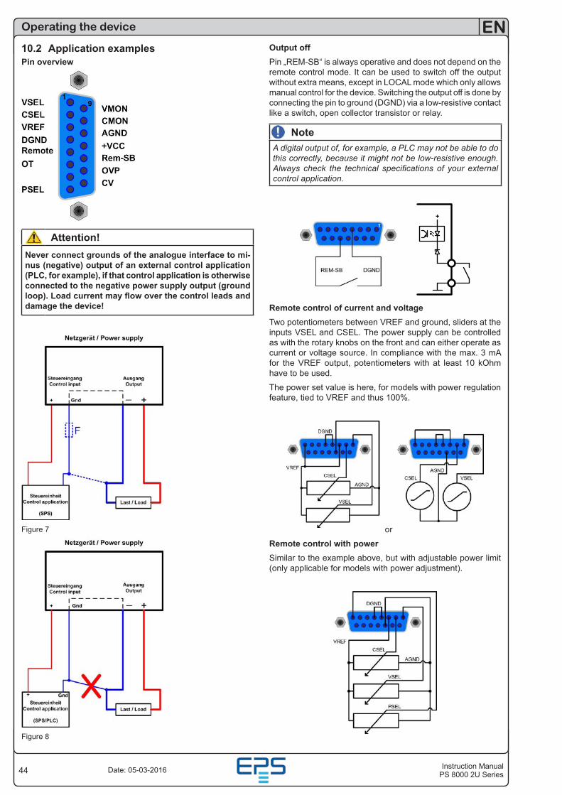
44
EN
Instruction ManualPS 8000 2U SeriesDate: 05-03-2016
Operating the device
10.2 Application examplesPin overview
Attention!Never connect grounds of the analogue interface to mi-nus (negative) output of an external control application (PLC, for example), if that control application is otherwise connected to the negative power supply output (ground loop). Load current may flow over the control leads and damage the device!
Figure 7
Figure 8
Output offPin „REM-SB“ is always operative and does not depend on the remote control mode. It can be used to switch off the output without extra means, except in LOCAL mode which only allows manual control for the device. Switching the output off is done by connecting the pin to ground (DGND) via a low-resistive contact like a switch, open collector transistor or relay.
NoteA digital output of, for example, a PLC may not be able to do this correctly, because it might not be low-resistive enough. Always check the technical specifications of your external control application.
+
Remote control of current and voltageTwo potentiometers between VREF and ground, sliders at the inputs VSEL and CSEL. The power supply can be controlled as with the rotary knobs on the front and can either operate as current or voltage source. In compliance with the max. 3 mA for the VREF output, potentiometers with at least 10 kOhm have to be used.
The power set value is here, for models with power regulation feature, tied to VREF and thus 100%.
or
Remote control with powerSimilar to the example above, but with adjustable power limit (only applicable for models with power adjustment).
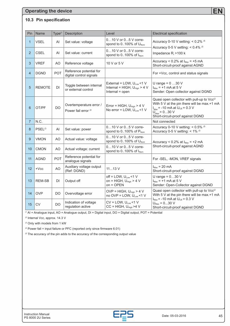
45Instruction ManualPS 8000 2U Series
EN
Date: 05-03-2016
10.3 Pin specification
Pin Name Type(1 Description Level Electrical specification
1 VSEL AI Set value: voltage 0…10 V or 0...5 V corre-spond to 0..100% of UNom
Accuracy 0-10 V setting: < 0.2% (5
Accuracy 0-5 V setting: < 0.4% (5
Impedance Ri >100 k2 CSEL AI Set value: current 0…10 V or 0...5 V corre-spond to 0..100% of INom
3 VREF AO Reference voltage 10 V or 5 V Accuracy < 0.2% at IMax = +5 mA Short-circuit-proof against AGND
4 DGND POT Reference potential for digital control signals For +Vcc, control and status signals
5 REMOTE DI Toggle between internal or external control
External = LOW, ULow <1 V Internal = HIGH, UHigh > 4 V Internal = open
U range = 0 …30 V IMax = +1 mA at 5 V Sender: Open collector against DGND
6 OT/PF DOOvertemperature error /
Power fail error (4
Error = HIGH, UHigh > 4 V No error = LOW, ULow <1 V
Quasi open collector with pull-up to Vcc(2 With 5 V at the pin there will be max.+1 mA IMax = -10 mA at UCE = 0.3 V UMax = 0...30 V Short-circuit-proof against DGND
7 N.C. Not connected
8 PSEL(3 AI Set value: power 0…10 V or 0...5 V corre-spond to 0..100% of PNom
Accuracy 0-10 V setting: < 0.5% (5
Accuracy 0-5 V setting: < 1% (5
9 VMON AO Actual value: voltage 0…10 V or 0...5 V corre-spond to 0..100% of UNom Accuracy < 0.2% at IMax = +2 mA
Short-circuit-proof against AGND10 CMON AO Actual voltage: current 0…10 V or 0...5 V corre-
spond to 0..100% of INom
11 AGND POT Reference potential for analogue signals For -SEL, -MON, VREF signals
12 +Vcc AO Auxiliary voltage output (Ref: DGND) 11...13 V IMax = 20 mA
Short-circuit-proof against DGND
13 REM-SB DI Output offoff = LOW, ULow <1 V on = HIGH, UHigh > 4 V on = OPEN
U range = 0…30 V IMax = +1 mA at 5 V Sender: Open-Collector against DGND
14 OVP DO Overvoltage error OVP = HIGH, UHigh > 4 V no OVP = LOW, ULow <1 V
Quasi open collector with pull-up to Vcc(2 With 5 V at the pin there will be max.+1 mA IMax = -10 mA at UCE = 0.3 V UMax = 0...30 V Short-circuit-proof against DGND
15 CV DO Indication of voltage regulation active
CV = LOW, ULow <1 V CC = HIGH, UHigh >4 V
(1 AI = Analogue input, AO = Analogue output, DI = Digital input, DO = Digital output, POT = Potential(2 Internal Vcc, approx. 14.3 V(3 Only with models from 1 kW(4 Power fail = input failure or PFC (reported only since firmware 6.01)(5 The accuracy of the pin adds to the accuracy of the corresponding output value
Operating the device
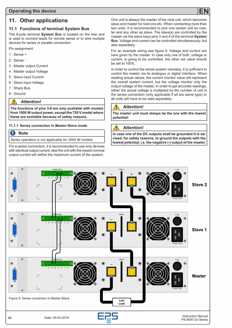
46
EN
Instruction ManualPS 8000 2U SeriesDate: 05-03-2016
Operating the device
Figure 9. Series connection in Master-Slave
11. Other applications11.1 Functions of terminal System BusThe 8-pole terminal System Bus is located on the rear and is used to connect leads for remote sense or to wire multiple devices for series or parallel connection.
Pin assignment:
1 : Sense +
2 : Sense -3 : Master output Current4 : Master output Voltage5 : Slave input Current6 : Slave input Voltage7 : Share Bus8 : Ground
Attention!The functions of pins 3-8 are only available with models from 1000 W output power, except the 720 V model where these are available because of safety reasons.
11.1.1 Series connection in Master-Slave mode
NoteSeries operation is not applicable for 3000 W models.
For a series connection, it is recommended to use only devices with identical output current, else the unit with the lowest nominal output current will define the maximum current of the system.
One unit is always the master of the next unit, which becomes slave and master for next one etc. When connecting more than two units, it is recommended to pick one certain unit as mas-ter and any other as slave. The slave(s) are controlled by the master via the slave input pins 3 and 4 of the terminal System Bus. Voltage and current can be controlled simultaneously, but also separately.
For an example wiring see figure 9. Voltage and current are here given by the master. In case only one of both, voltage or current, is going to be controlled, the other set value should be set to 100%.
In order to control the whole system remotely, it is sufficient to control the master via its analogue or digital interface. When reading actual values, the current monitor value will represent the overall system current, but the voltage monitor only the output voltage of the master. In order to get accurate readings, either the actual voltage is multiplied by the number of unit in the series connection (only applicable if all are same type) or all units will have to be read separately.
Attention!The master unit must always be the one with the lowest potential!
Attention!In case one of the DC outputs shall be grounded it is ad-vised, for safety reasons, to ground the outputs with the lowest potential, i.e. the negative (-) output of the master.
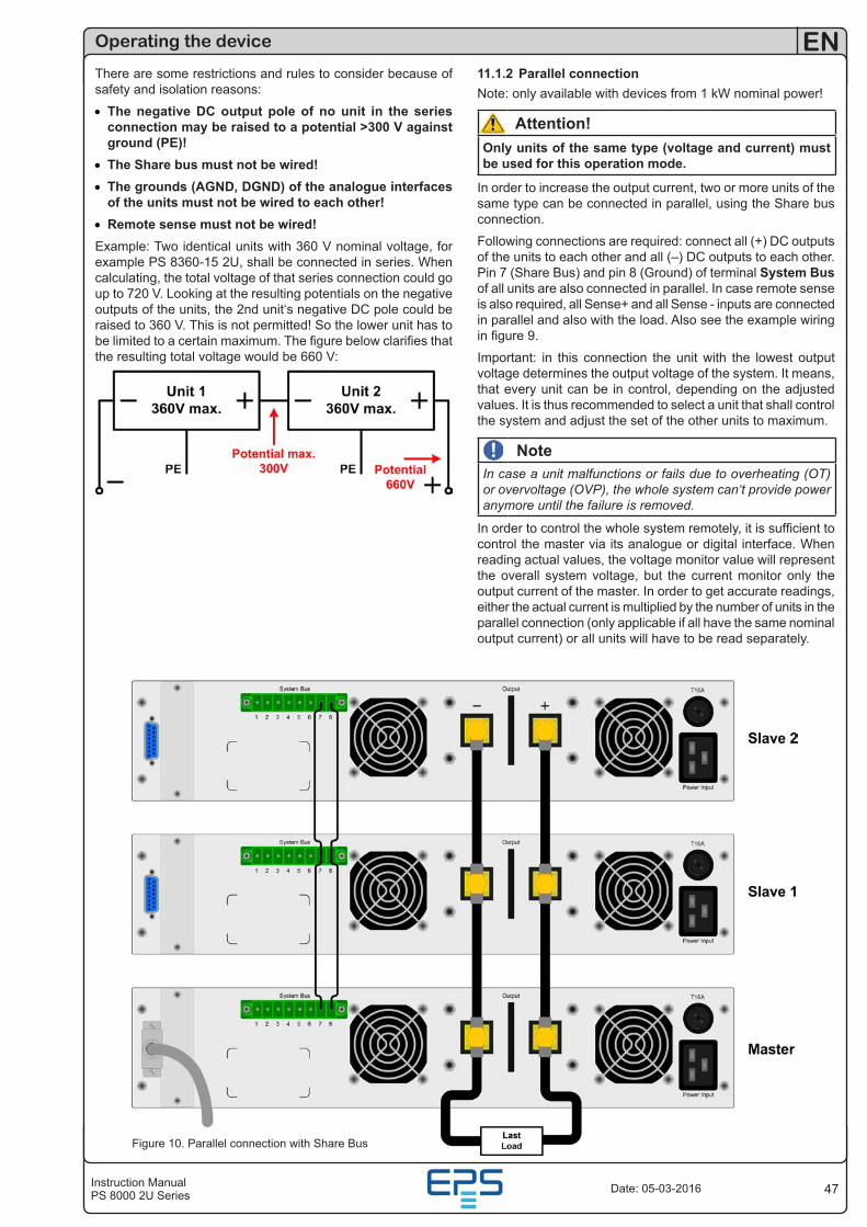
47Instruction ManualPS 8000 2U Series
EN
Date: 05-03-2016
Operating the device
Figure 10. Parallel connection with Share Bus
There are some restrictions and rules to consider because of safety and isolation reasons:
• The negative DC output pole of no unit in the series connection may be raised to a potential >300 V against ground (PE)!
• The Share bus must not be wired!• The grounds (AGND, DGND) of the analogue interfaces
of the units must not be wired to each other!• Remote sense must not be wired!Example: Two identical units with 360 V nominal voltage, for example PS 8360-15 2U, shall be connected in series. When calculating, the total voltage of that series connection could go up to 720 V. Looking at the resulting potentials on the negative outputs of the units, the 2nd unit‘s negative DC pole could be raised to 360 V. This is not permitted! So the lower unit has to be limited to a certain maximum. The figure below clarifies that the resulting total voltage would be 660 V:
11.1.2 Parallel connectionNote: only available with devices from 1 kW nominal power!
Attention!Only units of the same type (voltage and current) must be used for this operation mode.
In order to increase the output current, two or more units of the same type can be connected in parallel, using the Share bus connection.
Following connections are required: connect all (+) DC outputs of the units to each other and all (–) DC outputs to each other. Pin 7 (Share Bus) and pin 8 (Ground) of terminal System Bus of all units are also connected in parallel. In case remote sense is also required, all Sense+ and all Sense - inputs are connected in parallel and also with the load. Also see the example wiring in figure 9.
Important: in this connection the unit with the lowest output voltage determines the output voltage of the system. It means, that every unit can be in control, depending on the adjusted values. It is thus recommended to select a unit that shall control the system and adjust the set of the other units to maximum.
NoteIn case a unit malfunctions or fails due to overheating (OT) or overvoltage (OVP), the whole system can‘t provide power anymore until the failure is removed.
In order to control the whole system remotely, it is sufficient to control the master via its analogue or digital interface. When reading actual values, the voltage monitor value will represent the overall system voltage, but the current monitor only the output current of the master. In order to get accurate readings, either the actual current is multiplied by the number of units in the parallel connection (only applicable if all have the same nominal output current) or all units will have to be read separately.
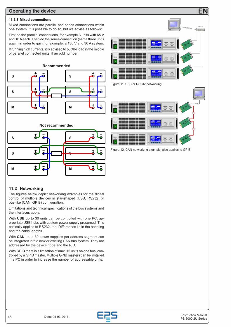
48
EN
Instruction ManualPS 8000 2U SeriesDate: 05-03-2016
Operating the device
11.1.3 Mixed connectionsMixed connections are parallel and series connections within one system. It is possible to do so, but we advise as follows:
First do the parallel connections, for example 3 units with 65 V and 10 A each. Then do the series connection (same three units again) in order to gain, for example, a 130 V and 30 A system.
If running high currents, it is advised to put the load in the middle of parallel connected units, if an odd number.
Recommended
Not recommended
11.2 NetworkingThe figures below depict networking examples for the digital control of multiple devices in star-shaped (USB, RS232) or bus-like (CAN, GPIB) configuration.
Limitations and technical specifications of the bus systems and the interfaces apply.
With USB up to 30 units can be controlled with one PC, ap-propriate USB hubs with custom power supply presumed. This basically applies to RS232, too. Differences lie in the handling and the cable lengths.
With CAN up to 30 power supplies per address segment can be integrated into a new or existing CAN bus system. They are addressed by the device node and the RID.
With GPIB there is a limitation of max. 15 units on one bus, con-trolled by a GPIB master. Multiple GPIB masters can be installed in a PC in order to increase the number of addressable units.
Figure 11. USB or RS232 networking
Figure 12. CAN networking example, also applies to GPIB
49Instruction ManualPS 8000 2U Series
EN
Date: 05-03-2016
12. Miscellaneous12.1 Accessories and optionsNote: Details about options and accessories are avalaible in separate user instruction manuals.
Following accessories are optionally available:
a) USB-to-Analogue interface UTA12Galvanically isolated remote control via USB (on PC side) and the device internal analogue interface.
b) Digital interface cardsPluggable and retrofittable, digital interface cards for USB, RS232, CAN, GPIB/IEEE (SCPI only), Profibus or Ethernet/LAN (SCPI only) are available. Details about the interfaces can be found in the interface cards user manual.
Following options are available:
a) High Speed RampingIncreased dynamics of the output voltage by reduced output capacity. It must be pointed out, that other output related val-ues also increase! This is a permanent modification which is not switchable.
b) Internal, active load with car ignition sequenceThis internal module, also called two-quadrants module, offers a power sink up to 150 W continuous or approx. 2400 W pulse peak. The main purpose is to discharge the device‘s output capacities faster than usual and thus to increase the dynamic behaviour of the output voltage, without worsen other output values. A second feature is the built-in car ignition sequence emulation which can be triggered by a button or remote signal. This is primarily used in the automotive industry. The module can be deactivated by a switch.
This option is available for models from 1000 W nominal power and up to 400 V nominal voltage.
12.2 Firmware updateA firmware update of the device should only be done if the device shows erroneous behaviour or if new features have been implemented.
In order to update a device, it requires a certain digital inter-face card, a new firmware file and a Windows software called „Update tool“.
These interfaces are qualified to be used for a firmware update:
• IF-U1 (USB)
• IF-R1 (RS232)
• IF-E1 (Ethernet/USB)
• IF-PB1 (Profibus/USB)
In case none of the above interface types is at hand, the device can not be updated. Please contact your dealer for a solution.
The update tool and the particular firmware file for your device are obtainable from the website of the device manufacturer, or are mailed upon request. The update too will guide the user through the semi-automatic update process.
Operating the device