Instruction Manual · product must be installed by a licensed plumber or gas fitter. Failure to...
24
Contents PLEASE read this first.......................................................... 2 Codes and standards........................................................... 2 G3B Gas burner at-a-glance .............................................. 3 Prepare site • prepare burner • mount burner ................ 4 Install gas piping .................................................................. 9 Wire burner ......................................................................... 10 Check system • start-up burner/appliance.................... 12 Perform checkout procedure • fill out certificate ........ 14 Maintenance and service procedures ........................... 17 Troubleshooting.................................................................. 19 Dimensions and mounting information .......................... 21 Replacement parts............................................................. 22 Instruction Manual Ratings Input: .................................................... 60,000 to 180,000 BTUH Fuels: ......................................... Natural gas or propane gas Max. supply pressure .............................14 INCHES W.C. Min. supply pressure ................................5 INCHES W.C. Manifold pressure .................................3.5 INCHES W.C. Electrical: Power ................................... 120V/60HZ/1-PHASE, 8 AMPS Motor.................................................. 1/50 HP, 3450 RPM Ignition: .................................. Norton hot surface ignitor, 120V Control: .................................Honeywell S89C primary control Agencies: ........................................................ CSA certified, U. S. The G3B burner has been assigned U. S. Patent No. 4397631 Installer/servicer — Except where specifi- cally stated otherwise, this manual must be used only by a qualified service technician. In the state of MA, this product must be installed by a licensed plumber or gas fitter. Failure to comply with this or other requirements in this manual could result in severe personal injury, death or substantial property damage. Handling — Handle burner (and hot surface ignitor) carefully to avoid cracking or breaking the ceramic ignitor. Ignitor protrudes slightly beyond burner head. Do not set burner on its end. User — Refer only to User’s Information manual for information regarding operation of this burner. The remainder of this manual is intended only for your service technician. The burner and heat exchanger must be inspected and started at least annually by your service technician. 126 Bailey Road North Haven, CT 06473 Ph 203-680-9401 Fx 203-680-9403 Carlin Combustion Technology, Inc. T ECH SUPPORT 800-989-2275 carlincombustion.com © Copyright 2015 — Carlin Combustion Technology, Inc.
Transcript of Instruction Manual · product must be installed by a licensed plumber or gas fitter. Failure to...

ContentsPLEASE read this first.......................................................... 2Codes and standards........................................................... 2G3B Gas burner at-a-glance .............................................. 3Prepare site • prepare burner • mount burner ................ 4Install gas piping .................................................................. 9Wire burner ......................................................................... 10Check system • start-up burner/appliance .................... 12Perform checkout procedure • fill out certificate ........ 14Maintenance and service procedures ........................... 17Troubleshooting .................................................................. 19Dimensions and mounting information .......................... 21Replacement parts............................................................. 22
Instruction Manual
RatingsInput: .................................................... 60,000 to 180,000 btuh
Fuels: .........................................Natural gas or propane gas
Max. supply pressure .............................14 inches w.c.
Min. supply pressure ................................5 inches w.c.
Manifold pressure .................................3.5 inches w.c.
Electrical: Power ...................................120v/60hz/1-phase, 8 amps
Motor..................................................1/50 hp, 3450 rpm
Ignition: .................................. Norton hot surface ignitor, 120v
Control: .................................Honeywell S89C primary control
Agencies: ........................................................ CSA certified, U. S.
The G3B burner has been assigned U. S. Patent No. 4397631
Installer/servicer — Except where specifi-cally stated otherwise, this manual must be used only by a qualified service technician. In the state of MA, this product must be installed by a licensed plumber or gas fitter. Failure to comply with this or other requirements in this manual could result in severe personal injury, death or substantial property damage.
Handling — Handle burner (and hot surface ignitor) carefully to avoid cracking or breaking the ceramic ignitor. Ignitor protrudes slightly beyond burner head. Do not set burner on its end.
User — Refer only to User’s Information manual for information regarding operation of this burner. The remainder of this manual is intended only for your service technician. The burner and heat exchanger must be inspected and started at least annually by your service technician.
126 Bailey Road North Haven, CT 06473Ph 203-680-9401 Fx 203-680-9403
Carlin Combustion Technology, Inc.
Tech support 800-989-2275 carlincombustion.com
© Copyright 2015 — Carlin Combustion Technology, Inc.

Model G3B Gas burner — Instruction manual
MNG3B Gas 0410152
General information
Burner applications
Follow all instructions in this manual and the appliance manual. Where appliance instructions differ from this manual, follow the appliance instruc-tions. Read the label attached to the burner air tube to verify the burner is correct for the appliance being used. See pages 6 and 7 for procedures.
Damage or shortage claims
The consignee of the shipment must file damage or shortage claims immediately against the transportation company.
When calling or writing about the burner . . .
Please provide us with the burner serial number and burner model number to assist us in locating information. Enter this information on the Installation Certificate in this manual. The certificate information can be helpful when troubleshooting or obtaining replacement parts.
PLEASE read this first . . .
Special attention flags
Please pay particular attention to the following when you see them through-out this manual.
Notifies you of hazards that WILL cause severe personal injury, death or substantial property damage.
Notifies you of hazards that CAN cause severe personal injury, death or substantial property damage.
Notifies you of hazards that WILL or CAN cause minor personal injury or property damage.
Notifies you of special instructions on installation, operation or maintenance that are important, but are not normally related to injury or property damage hazards.
Follow the guidelines below to avoid potential severe personal injury, death or substantial property damage.
Installer/service technician . . .
• Readall instructionsbeforeproceeding.Performallprocedures,and in the order given to avoid potential of severe personal injury, death or substantial property damage.
• Beforeleavingthesiteafterstartuporservice,reviewtheUser’sinformation manual with the user. Make the user aware of all potential hazards and perform the training outlined below.
Train the user . . .
• Toproperlyoperatetheburner/applianceperthismanual,theappliance instructions and the User’s information manual.
• Tokeepthismanualatorneartheburner/applianceforreadyaccess by the user and service technician.
• Tocontacttheservicetechnician,gassupplierorfiredepartmentshould the user smell gas.
• Tokeeptheappliancespacefree of flammable liquids or vapors and other combustible materials.
• Donotuselaundryproducts,paints,varnishesorotherchemicalsintheroomoccupiedbytheburner/appliance.
• Tocontacttheservicetechnicianatleastannuallyforstartupandburner/applianceservice.
When servicing the burner . . .
• Disconnect electrical supply to burner before attempting to service to avoid electrical shock or possible injury from moving parts.
• Burnerandappliancecomponentscanbeextremelyhot.Allow all parts to cool before attempting to handle or service to avoid potential of severe burns.
• Handletheceramicignitorwithcaretoavoidbreakingorcrackingthe ignitor. Do not handle ignitor when it is hot. NEVER touch the surface of the ignitor with bare fingers. Body oils can cause damage.
Codes and standards
The installer/servicer is solely responsible for compliancewith all applicable codes and standards.
Burner listings/approvals
Carlin G3B gas burners are CSA certified for use with natural gas or propane gas, United States installations only.
BurnersareNYC/MEAapproved.MEA-369-89-E.
Installation:
Burner/applianceinstallationsmustcomplywiththelatesteditionsof:
• “InstallationofDomesticGasConversionBurners,”ANSIZ21.8.
• NationalFuelGasCode,ANSIZ223.1/NFPA54.
• NationalElectricalCode,ANSI/NFPA70.
• Alladditionalapplicablenational,stateandlocalcodes.

Model G3B Gas burner — Instruction manual
MNG3B Gas 041015 3
G3B Gas Burner At-a-Glance
1 Air tube, with powder coat paint finish
2 Flameholder
3 Hot surface ignitor
4 Adjustable flange
5 Rear ignitor assembly with terminal boots
6 Ignition tube assembly mounting plate
7 Pedestal legs
8 Burner gas inlet connection (see page 8)
9 Combination gas valve (with integral gas pressure regulation — set for 3½” w.c. outlet pressure)
10 Control panel
11 Terminal strip
12 Primary control (Honeywell Model S89C primary control, for use with flame rectification)
13 Control transformer, 120 vac / 24 vac, 40 va
14 Gas valve on indicator light
15 Motor relay
16 High-efficiency motor
17 Blower housing (cast aluminum), with powder coat paint finish
18 Air inlet tube assembly
19 Air throttle indicator — Only a single adjustment required for setting combustion air; see page 8 for starting setting based on appliance model and input)

Model G3B Gas burner — Instruction manual
MNG3B Gas 0410154
1. Prepare Site • Prepare Burner • Mount Burner
Inspect installation site
Inspect, repair and/or replace vent system
Do not install this burner unless you have verified the entire vent system and the appliance are in good condition and comply with all applicable codes. And . . .
The vent and chimney must be sized and constructed in ac-cordance with all applicable codes. If intended for use with an oil burner as well, the vent system must comply with relevant codes for both gas and oil firing.
The vent system must not be pressurized unless the vent piping and vent system are designed accordingly. The vent must provide draft at all times (negative pressure in vent).
Do not install or use an existing manual damper in the vent connector or vent.
Do not connect the appliance vent connector to a chimney or vent serving a fireplace, incinerator or solid-fuel-burning apparatus.
In a cold climate, do not vent into a masonry chimney that has one or more sides exposed to the outside. Install a listed stainless steel liner to vent the flue products.
A defective vent system could result in severe personal injury, death or substantial property damage.
Vent/chimney sizing
• Followalllocalcodeswhensizingtheventandchimey
• Refer to the appliance manufacturer’s manual, when available, forventing recommendations
Prepare vent/chimney
• Secureallmetalventjointswithscrews,followingtheventmanufactur-er’s instructions. Seal all joints in the vent system and chimney. Repair masonry chimney lining and repair all mortar joints as needed.
• Installadouble-actingbarometricdraftregulatorintheventpiping.(Thedamper must be located in the same space as the appliance.) Install a manual reset spill switch in the top of the draft regulator outlet. Wire the switchintotheappliancelimitcircuittoshutofftheappliance/burnerifsustained downdraft should occur.
• Providesupportfortheventpiping.Donotresttheweightofanyofthevent piping on the appliance flue outlet.
Figure 1 Vent and vent connector installation
Verify clearances
• Verifythatclearancesrequiredforservice/maintenancecomplywiththe appliance manual and applicable codes. Provide at least 6 inches aroundburnerand24inchesinfrontofburnerpanelforserviceaccess.
Model G3B Gas burner — Instruction manual
MNG3B Gas 041015 5
1. Prepare Site • Prepare Burner • Mount Burner (continued)
Inspect installation site
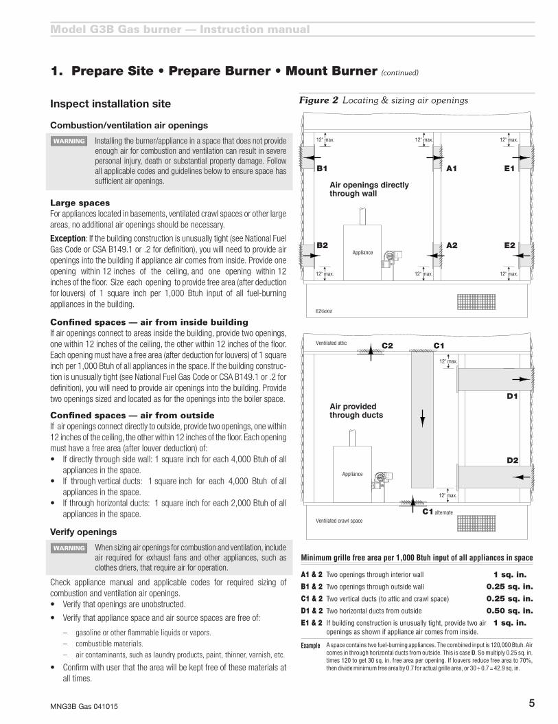
Combustion/ventilation air openings
Installingtheburner/applianceinaspacethatdoesnotprovideenough air for combustion and ventilation can result in severe personal injury, death or substantial property damage. Follow all applicable codes and guidelines below to ensure space has sufficient air openings.
Large spacesFor appliances located in basements, ventilated crawl spaces or other large areas, no additional air openings should be necessary.
Exception:Ifthebuildingconstructionisunusuallytight(seeNationalFuelGasCodeorCSAB149.1or.2fordefinition),youwillneedtoprovideairopenings into the building if appliance air comes from inside. Provide one openingwithin12inchesoftheceiling,andoneopeningwithin12inches of the floor. Size each opening to provide free area (after deduction forlouvers)of1squareinchper1,000Btuhinputofallfuel-burningappliances in the building.
Confined spaces — air from inside buildingIf air openings connect to areas inside the building, provide two openings, onewithin12inchesoftheceiling,theotherwithin12inchesofthefloor.Each opening must have a free area (after deduction for louvers) of 1 square inchper1,000Btuhofallappliancesinthespace.Ifthebuildingconstruc-tionisunusuallytight(seeNationalFuelGasCodeorCSAB149.1or.2fordefinition), you will need to provide air openings into the building. Provide two openings sized and located as for the openings into the boiler space.
Confined spaces — air from outsideIf air openings connect directly to outside, provide two openings, one within 12inchesoftheceiling,theotherwithin12inchesofthefloor.Eachopeningmusthaveafreearea(afterlouverdeduction)of:• Ifdirectlythroughsidewall:1squareinchforeach4,000Btuhofall
appliances in the space.• Ifthroughverticalducts:1squareinchforeach4,000Btuhofall
appliances in the space.• Ifthroughhorizontalducts:1squareinchforeach2,000Btuhofall
appliances in the space.
Verify openings
When sizing air openings for combustion and ventilation, include air required for exhaust fans and other appliances, such as clothes driers, that require air for operation.
Check appliance manual and applicable codes for required sizing of combustion and ventilation air openings.• Verifythatopeningsareunobstructed.
• Verifythatappliancespaceandairsourcespacesarefreeof:
– gasoline or other flammable liquids or vapors.– combustible materials.– air contaminants, such as laundry products, paint, thinner, varnish, etc.
• Confirmwithuserthattheareawillbekeptfreeofthesematerialsatall times.
Figure 2 Locating & sizing air openings

Model G3B Gas burner — Instruction manual
MNG3B Gas 0410156
Prepare the appliance
Burnerinput:Installagasburnersizedforthenormalinputrating of the appliance. Do not install a burner with a higher firing rate than the appliance rating. Do not install a burner withafiringratemorethan10%lowerthantheappliancerating. The appliance and vent system could be damaged due to condensation.
Sealtheappliance:Sealallflue-gascontainingjoints.Sealall connections to the vent piping or breeching.
Clean and check the appliance: Clean the appliancethoroughly. Test all electrical components and verify the relief valve works (boilers only).
Verify combustion chamber dimensions comply with the minimum dimensions shown in Figure 3. Install or replace combustion chamber liner if required by the appliance manufacturer. The burner air tube must not extend into the combustion chamber. The end of the burner air tube must be within¼”oftheinsidefaceofthecombustionchamber.Ifthespacearoundtheburnerairtubeismorethan¼”,wraptheburnerairtubewithminimum2300-°F-ratedceramicfiberblanket to seal off the gap. Notice that the flameholder may extend slightly into chamber as shown in Figure 3.
Repair or replace damaged appliance components. Inspect the appliance thoroughly. Follow appliance manufacturer’s guidelines for repair or replacement of any component found defective.
When cleaning the appliance or working with ceramic fiber refractories or fiberglass insulation, see WARNING on page 7.
Failure to comply with the above could result in severe personal injury, death or substantial property damage.
1. Prepare Site • Prepare Burner • Mount Burner (continued)
Input Minimum chamber dimensions, Inches
(Note 1)(Using 2300ûF or higher refractories)
BtuhSquare
L x W x HVertical cylinder
Diameter x H
60,000 7 x 7 x 9 8 x 9 70,000 7½ x 7½ x 9 8½ x 9100,000 8 x 8 x 9 9 x 9120,000 9 x 9 x 9 10 x 9140,000 10 x 10 x 9 11 x 9160,000 11 x 11 x 9 12 x 9180,000 12 x 12 x 9 13 x 9Note 1: Rectangular chambers of similar floor area are equally acceptable, but the L/W ratio should not
exceed 2 and the width should be at least 5 inches.
Figure 3 Minimum combustion chamber dimensions

Model G3B Gas burner — Instruction manual
MNG3B Gas 041015 7
1. Prepare Site • Prepare Burner • Mount Burner (continued)
Inspect burner and components
Do not install or operate the burner if any component is damaged or if burner does not comply with the specifications and guidelines in this manual and the appliance manual.
Air tube insertion length (UTL)
• Usableairtubelength(UTL) is the distance from mounting flange to end of air tube.
• Verifythattheendoftheairtubewillbeflushwith,ornomorethan¼ inch short of, the inside of the appliance combustion chamber front wall when the burner is mounted. See Figure 3, page 6.
• MinimumUTL is1¾ inches.MaximumUTL is tube length less1¾inches.Tubesareavailablein6-inch,9-inchand12-inchlengths.
• Notice that the flameholder may extend slightly into chamber asshown.
Ceramic fiber or Fiberglass insulation
Ceramic fiber materials, such as chamber liners, may contain carcinogenic particles (chrystobalites) after exposure to heat. Airborne particles from fiberglass or ceramic fiber components have been listed as poten-tially carcinogenic by the State of California. Take the following precautions when removing, replacing and handling these items.
Avoid breathing dust and avoid contact with skin or eyes. Wear long-sleeved, loose-fitting clothing, glovesandeyeprotection.UseaNIOSHN95certifiedrespirator. This respirator meets requirements for protection from chrystobalites. Actual job requirements or NIOSH regulations may require other or additional protection. For information, refer to the NIOSH website, http://www.cdc.gov/niosh/homepage.html.
Ceramic fiber removal:Topreventairbornedust,thor-oughly wet ceramic fiber with water before handling. Place ceramic fiber materials in a plastic bag and seal to dispose.
Avoid blowing, tearing, sawing or spraying fiber-glass or ceramic fiber materials. If such operations are necessary, wear extra protection to prevent breathing dust.
Wash work clothes separately from other laundry. Rinse clothes washer thoroughly afterwards to prevent contamination of other clothing.
NIOSH First aid procedures:
Eye exposure — irrigate immediately
Breathing — fresh air.
Prepare appliance for burner mounting
The universal flange supplied with G3B Gas burners is intended only for firing chambers with negative overfire pressure. The G3B burner must not be installed on a product that operates with a pressurized combustion chamber. Failure to comply could result in severe per-sonal injury, death or substantial property damage.
• Seepage21forrequireddimensionsandboltlocations.

Model G3B Gas burner — Instruction manual
MNG3B Gas 0410158
1. Prepare Site • Prepare Burner • Mount Burner (continued)
Mount burner in appliance
• Verifyapplianceburnerfrontplatedimensionsperpage21.
• Slidegasketsuppliedwithburneroverendofairtube.
• Insertburnerintoapplianceopeningandboltinplace.
Inspect burner and components
Drill or ream gas orifice to size (initial installation)
You must disconnect power to burner and close main manual gas valve before proceeding. Failure to do so could result in severe personal injury, death or substantial property damage.
You must drill or ream the burner orifice to the size given in Figure 4. The orifice is shipped with a pilot hole only. Firing the burner with the orifice as shipped can result in damage to the burner.NeverfiretheG3Bburnerbelow60,000Btuhinput.The flameholder can overheat, resulting in potential severe personal injury, death or substantial property damage.
1. After drilling or reaming orifice to correct size, thread orifice fitting into orifice nipple as shown in Figure 4.
Install gas valve on burner
1. Read WARNING’s on page 9 before installing gas valve.
2. Applyasmallamountofpipedope(suitableforpropanegas)togasvalve outlet connection, gas line elbow and orifice nipple. Assemble elbow and orifice nipple to gas valve.
To avoid damage to gas valve, do not hold valve with a pipe wrench or over-tighten. Use only a crescent wrench or other means. Failure to comply could result in severe personal injury, death or substantial property damage.
3. Insert orifice nipple into burner gas connection and secure in place using the two Allen screws.
4. Connect gas valve wires to gas valve.
Inspect/redrill gas orifice when required
1. Turnoffpowertotheburner/appliancebeforeproceeding.
2. Closemainmanualgasvalveingaslinetoburner.Thendisconnecttheground joint union to allow rotating burner combination gas valve.
You must disconnect power to burner and close main manual gas valve before proceeding. Failure to do so could result in severe personal injury, death or substantial property damage.
3. LoosenAllenscrewssecuringgaslinetoburnergasconnection.
4. Remove combination gas valve (item 9, page 3) and gas piping to burner gasconnection(item8,page3)onburnerairtube.
5. ReadcorrectorificedrillsizefromFigure4.Thencheckactualorificesize using that size twist drill bit.• If gas orifice is smaller than required, redrill orifice to correct size,
ifnecessary.Replacegasvalveandpiping,usingonlypipedopelistedforusewithliquefiedpetroleumgases.
• If gas orifice is larger than required, obtain a replacement gas orifice fitting. Drill orifice hole in replacement orifice fitting.
Hot surface ignitor
• Inspecttheburnerfromairtubeend.Thehotsurfaceignitormustextendslightlypasttheendoftheburner.
• Carefully inspecttheignitor,ensuringit is intact,withnocracksorvisualsignsofdegradation.
• Donottouchtheignitorwithbarehands.Bodyoilscancausedeteriorationofthesiliconcarbide.
• Replaceignitorifthereareanysignsofdamage.
You must allow ignitor to cool before attempting to handle. Failure to do so could result in severe personal injury or damage to the ignitor.
Inspect components and wiring
• Visuallyinspectallburnercomponentsandwiring.
• Verifythatwiringisintactandleadsaresecurelyconnected.
• Verifythatallburnercomponentsareingoodcondition.
Figure 4 Orifice and gas valve installation
InputBtuh
Burner orifice drill size Diameter, inches
Air throttle turns (appr.) Notes 1 & 2Note 1 Natural Gas Propane Gas
60,000 #28 (0.141) #33 (0.113) 0 70,000 #24 (0.152) Z\, (0.125) ½ 80,000 #20 (0.161) #30 (0.129) ¾ 90,000 #17 (0.173) #28 (0.141) 1100,000 #14 (0.182) #25 (0.150) 1½110,000 #11 (0.191) #22 (0.157) 1¾120,000 #7 (0.201) #20 (0.161) 2¼140,000 #3 (0.213) #16 (0.177) 3160,000 A (0.234) #12 (0.189) 4¼180,000 D (0.246) #7 (0.201) 9
Note 1: High altitude applications: The maximum burner input at sea level is 180,000 Btuh. Reduce this capacity by 4% per 1,000 feet above sea level. Example — max. capacity at 5,000 feet is 144,000 Btuh (20% reduction).
Note2: Usethisasthestartingsettingonly.Adjustairthrottle,ifnecessary,afterperformingcombustion testing (see page 14).
Model G3B Gas burner — Instruction manual
MNG3B Gas 041015 9
2. Install Gas Piping from Meter to Combination Gas Valve
Code complianceTheburner/applianceinstallationmustcomplywithcodeslistedonpage2andany other locally applicable codes.
Piping from meter to burner
Connect from the gas supply to the burner combination gas valve inlet using new, clean black iron pipe and malleable iron fittings only. Do not use copper, brass, cast iron or galvanized pipe or fittings.
Provide support for gas piping. Do not rest weight of piping on burner gas valve.
Apply pipe dope sparingly at all joints. Use only pipe dope listed for use with propane gas. Do not use pipe sealing tape.
Do not hold gas valve with pipe wrench. Use crescent wrench or other smooth-jawed device. Do not over-tighten.
Failure to comply with above could result in severe personal injury, death or substantial property damage.
1. If possible, install a new gas line directly from the gas meter. If you are using an existing gas line, verify it is clean and in good condition, and verify it is large enough to handle the load of all connected appliances.
2. Whenbranchingfromacommongasline,donottapofffromthebottomof horizontal sections — only from the side or top.
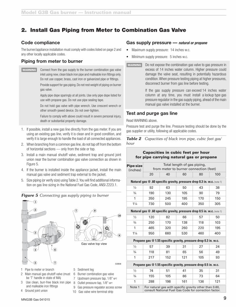
3. Install a main manual shutoff valve, sediment trap and ground joint union near the burner combination gas valve connection as shown in Figure5.
4. If the burner is installed inside the appliance jacket, install the main manual gas valve and sediment trap external to the jacket.
5. Sizepiping(orverifysize)usingTable2.Youwillfindadditionalinforma-tionongaslinesizingintheNationalFuelGasCode,ANSIZ223.1.
Gas supply pressure — natural or propane
• Maximumsupplypressure:14inchesw.c.
• Minimumsupplypressure:5inchesw.c.
Do not expose the combination gas valve to gas pressure in excess of 14 inches water column. Higher pressure could damage the valve seat, resulting in potentially hazardous condition. When pressure testing piping at higher pressures, disconnect burner from gas line before testing.
If the gas supply pressure can exceed 14 inches water column at any time, you must install a lockup type gas pressure regulator in the gas supply piping, ahead of the main manual gas valve installed at the burner.
Test and purge gas line
Read WARNING above.
Pressure test and purge the line. Pressure testing should be done by the gas supplier or utility, following all applicable codes.
Table 2 Capacities of black iron pipe, cubic feet gas/hour
Figure 5 Connecting gas supply piping to burner
1 Pipe to meter or branch2Mainmanualgasshutoffvalve(must
be ‘T’ handle in state of MA)3 Use clean, burr-free black iron pipe
and malleable iron fittings4 Ground joint union
5Sedimentleg 6 Burner combination gas valve7Upstreampressuretap,1/8”npt
8Outletpressuretap,1/8”npt
9 Gas pressure regulator access screw10Gasvalvewireterminalstrip

Model G3B Gas burner — Instruction manual
MNG3B Gas 04101510
3. Wire Burner
Code compliance
Theburner/applianceinstallationmustcomplywithcodeslistedonpage2andanyotherlocallyapplicablecodes.
General wiring requirements
Read and follow the guidelines in this manual. Failure to comply could result in severe personal injury, death or substantial property damage.
Electrical shock hazard — Disconnect electrical supply to the burner before attempting to service. Failure to comply could result in severe personal injuiry, death or substantial property damage.
Figure 6 Ladder wiring diagram
Electrically ground burner — The burner must be grounded in accordance with local codes or, in the absence of local codes,withtheNationalElectricalCode,ANSI/NFPA70(inCanada, the Canadian Electrical Code Part 1, C.S.A. Standard C22.1.)
Label all wires before removing for servicing. Wiring errors couldresultinunsafeappliance/burneroperation.
Read appliance manufacturer’s instructions completely before wiring burner.
Check polarity carefully. If hot and neutral wires are reversed at appliance power source, the control will not operate.
If replacing any of the wire supplied with the burner, use minimum#14AWG125°Corbetter.

Model G3B Gas burner — Instruction manual
MNG3B Gas 041015 11
3. Wire Burner (continued)
Figure 7 Wiring diagram — wire routing
M
L1
L2
T
T
Red
Gray
Bk
Wh
Blue
Br
Or
Yel
24V
HSI
L1
L2
HSI
VALVE
VALVE (GND)
Red
Pur
Yel
BlueBk
Wh
Pur
MV MV
TH/TR
Red
Bk
Bk
Bk
Wh
Bk
Gn
Yel
Bk
Red
Red
BkBk
Motor120 VAC
Motorrelay
Honeywell S89Ccontrol
Hot surfaceignitor
40Transformer
VA
Valve onlight
Terminalstrip
Motorend switch
Thermostat **
Spill switch (if used)(may also be wiring inthe 120-v limit circuit)
**
120-v limitcircuit
120 VAC
GND
Hot
Neu
Control panel enclosure
Combinationgas valve
NOTICE: Line voltage polarityThe hot and neutral power wiresmust connect as shown for correctoperation of the burner controls.
Br = brownGr = green
Bk = blackBlue = blue
Or = orangePur = purpleGray = gray
Wire color coding
120 factory wiringVAC
24 factory wiringVAC
120 field wiringVAC
24 field wiringVAC
Wire connector
G3B01
Line switch **
** Supplied by installer
Red = redWh = whiteYel = yellow
Bk
GND (BURNER) Gn
Yel
24V (GND)
Yel
Gnd
Connect ground wiresto green terminal stripscrews when replacinga Fenwal control with aHoneywell S89C.
Verify power supply
1. The burner requires a120vac/60hz/single-phase power supply.Thecurrentdrawwillbeaproximately8.0amps.Protectlinewitha10-ampor15-ampfuseorbreaker.
2. The120vac power connections to the burner must be connected as shown in Figure 7. The control is polarity-sensitive, and will not work if the hot and neutral lines are reversed.
3. Verifythatthepowersupplytotheburnerisnolessthan102vac nor morethan132vac.
Model G3B Gas burner — Instruction manual
MNG3B Gas 04101512
4. Check System • Start-up Burner/Appliance
Inspect/check system
Before starting the burner and appliance, verify the system has been installed as directed by this manual and the appliance instructions.
Check gas piping for leaks
Disconnect the burner from the gas supply line if gas line test pressure will exceed 14 inches w.c. Exposing the burner combination gas valve to pressure higher than 14 inches w.c. can damage the valve seat, resulting in potentially unsafe operation.
You can usually test the gas piping by allowing the line to fill with gas to main regulator outlet pressure.
1. Shut off gas flow to all appliances connected to the meter.
2. Iftestpressurewillbelessthan14inchesw.c.,turntheburnercombi-nation gas valve knob to OFF. If test pressure will be higher than 14 inches, disconnect the burner from the gas line by shutting off the mainmanualgasvalveinstalledneartheburner(perFigure5,page9)and disconnecting the ground joint union. See warning above.
3. Watch the gas meter dial. For a one half cubic foot per revolution dial, thereshouldbenomovementofthedialforatleast5minutes.Forlarger volumes per revolution, increase this time proportionately.
4. If you detect a gas leak, locate the leak with a soap suds mixture and repair it. Then test the system for leaks again.
Do not test for leaks with an open flame. And do not use oxygen as a test gas. Either of these could cause an explosion, resulting in severe personal injury, death or substantial property damage.
Bleed gas line
Purge all air from the gas line. Purge to outside of the building, NEVER into the appliance or burner.
Leak test near-burner gas piping
If piping near burner has not already been pressure tested, open main manual gas valve on supply to burner and smell around area for any signs of gas. Apply a soap suds mixture to all gas piping joints near burner and check for any leaks. If any leaks appear, repair before proceeding and retest.
Set air throttle
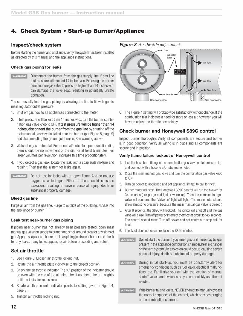
1. SeeFigure8.Loosenairthrottlelockingnut.
2. Rotatetheairthrottleplateclockwisetotheclosedposition.
3. Checktheairthrottleindicator.The“0”positionoftheindicatorshouldbe even with the end of the air inlet tube. If not, bend the arm slightly until the indicator reads zero.
4. Rotate air throttle until indicator points to setting given in Figure 4, page8.
5. Tightenairthrottlelockingnut.
Figure 8 Air throttle adjustment
Do not start the burner if you smell gas or if there may be gas present in the appliance combustion chamber, heat exchanger or the vent system. An explosion could occur, causing severe personal injury, death or substantial property damage.
During initial start-up, you must be constantly alert for emergency conditions such as fuel leaks, electrical malfunc-tions, etc. Familiarize yourself with the location of manual shutoff valves and switches so you can quickly use them if needed.
If the burner fails to ignite, NEVER attempt to manually bypass the normal sequence of the control, which provides purging of the combustion chamber.
6. The Figure 4 setting will probably be satisfactory without change. If the combustion test indicates a need for more or less air, however, you will have to adjust the throttle accordingly.
Check burner and Honeywell S89C control
Inspect burner thoroughly. Verify all components are secure and burner is in good condition. Verify all wiring is in place and all components are secure and in position.
Verify flame failure lockout of Honeywell control
1. Install a hose barb fitting in the combination gas valve outlet pressure tap and connect with a hose to a U-tube manometer.
2. Closethemainmanualgasvalveandturnthecombinationgasvalveknobto ON.
3. Turn on power to appliance and set appliance limit(s) to call for heat.
4. Burnermotorwillstart.TheHoneywellS89Ccontrolwillruntheblowerfor34 seconds (pre-purge and ignitor warm-up). Then the combination gas valvewillopenandthe“Valveon”lightwilllight.(Themanometershouldshow almost no pressure, because the main manual gas valve is closed.)
5. After6seconds,theS89Cwilllockout.Theignitorwillshutoffandthegasvalvewillclose.Turnoffpowerorinterruptthermostatcircuitfor45seconds.The control should reset. Turn off power and set controls to stop call for heat.
6. Iflockoutdoesnotoccur,replacetheS89Ccontrol.

Model G3B Gas burner — Instruction manual
MNG3B Gas 041015 13
4. Check System • Start-up Burner/Appliance (continued)
Installer/servicer Shouldoverheatingoranemergencyoccur,immediately:
•Shutoffmainmanualgasvalve.
•Shutoffpowertoburner.
NOTICE:Undersomecircumstancespowershouldremainonforwaterpumpsorcirculatingblowers.Determineproperresponsebeforeattemptingstart-up.
Ifburnerfailsignitiononseveralattempts,closegasvalveanduseburnerblowertopurgeappliancebeforerestart.
Start-up & operation Donotstarttheburnerifthecombustionchambercontains
residualgas.Allowgastodisperse.Failuretocomplycouldresult in severe personal injury, death or substantial property damage.
Power ON Openallmanualgaslinevalves.Turnburnercombinationgasvalveknobto“ON.”Closethelineswitch.(Ifburnerdoesnotfollowsequencebelow,seetroubleshootingsuggestionsonpages19and20.)
Stand-by (Nocallforheat)Controlwaitsforheatcall.
Call for heat Setoperatingcontrolandalllimitcontrolstocallforheat.ThethermostatcircuitmustbeclosedandpowercomingtocontrolpanelL1andL2terminals
Burner on Themotorstarts.Thehotsurfaceignitorstarts.Themotorcentrifugalswitchmakes.
Pre-purge Theprimarycontrolallows34seconds forpre-purgeandignitorwarm-up.
Gas valve on After the pre-purge/ignitor warm-up period, the primarycontrol activates the gas valve(ifmotorcentrifugalswitchisclosed).Thegreen“Gasvalveon”lightturnson.
TFI Theprimarycontrolturnsofftheignitorwithin2to6secondsaftergasvalveactivation.Whenthecontroldeactivatestheignitor, itbeginscheckingforflamesignal. Ifflameisnotdetectedwithin6secondsaftergasvalveactivation, theprimary control will lockout with continuous purge (seefollowing).
Run period Theburnercontinuesfiringduringcallforheatiftheflamerod(hotsurfaceignitor)sensesflame.Thegreen“Gasvalveon”lightremainsonduringnormalrunning,indicatinggasvalve is energized.
Shutdown Whenthecallforheatends,theprimarycontrolimmediatelydeactivatesthegasvalveandblower.Theburnerreturnstostand-by.
Flame failure Iftheprimarycontrollosesflamesignalduringarunperiod,itdeactivatesthegasvalvewithin2seconds.Thecontrolrestarts the heating cycle, beginning with a 34-secondpre-purge/ignitorwarm-upperiod,thena6-secondtrialforignition.Ifignition/flamesensingissuccessful,theburnerreturnstonormaloperation.Iftheattemptisnotsuccessful,theprimarycontrolwilllockout.
Lockout IftheprimarycontroldoesnotsenseflamewithintheTFItimelimitaftergasvalveactivation(6seconds),lockout occurs.Thecontroldeactivatesthegasvalve.Theblowermotorcontinuestorun,providingapost-purgeoftheburnerand appliance.
Reset Toresetafteralockout,turnoffpowertoburnerorinterruptthethermostatcircuitforatleast45seconds.Thenrestorepower(orthermostatcircuit).Burnershouldrestart.
Ignition and flame sensingIgnition TheG3Bburnerusesasiliconcarbidehotsurface ignitor
forignition.TheHoneywellS89Cprimarycontrolfeeds120vacpowertotheignitorandallowstimefortheignitortowarmuptoignitiontemperatureduringtheburnerpre-purgeperiod.
Sensing TheS89Cprimarycontrolusesflamerectificationtodetectflame,withthehotsurfaceignitoractingasthe“flamerod.”
Before starting burner, verify:
❏ Burner/applianceinstalledperapplianceinstructionmanual?
❏ BurnerorificesizeandairthrottleverifiedagainstFigure4,page8?
❏ Burner/applianceinstalledperallapplicablecodes?
❏ Installation site has adequate ventilation openings and ventsystem?
❏Gassupplylineingoodconditionandsizedcorrectly?
❏Allgaslinejointssealedwithpipedopelistedforusewithliquefiedpetroleumgases?
❏Gassupplypressuretocombinationgasvalvechecked?
❏ Regulatorinstalledifpressurecanexceed14inchesw.c.?
❏Airpurgedfromgasline?
❏Gaspipingcheckedforleaks?
❏Wiringinstalledperburnerandapplianceinstructionmanuals?

Model G3B Gas burner — Instruction manual
MNG3B Gas 04101514
5. Perform Checkout Procedures • Fill Out Certificate
Make final burner adjustments
Check for leaks in gas piping
❏ Smellaroundburnertomakesurethereisnogasleakinnear-burnerpiping.Verify integrityofgas line jointsbetweencombinationgasvalveandburnergasinlettappingusingsoapsudsmixture.Verifygaspipingisfullysupported,independentlyofburner.
Check for leaks from burner components
❏ Smellaroundburnertomakesurethereisnoleakagefromtheburnerinletairtube,blowerhousingorairtube.Verifyburner isproperlysupported and flange is securely tightened.
If you detect leakage from any burner component, immediately close the main manual gas valve. Use a soap suds mixture to determine leakage location. Replace burner if leakage cannot be corrected by properly securing components. You may have to restart the burner several times during leakage testing since the control will lockout when flame is not detected. Failure to correct leakage problems could result in severe personal injury, death or substantial property damage.
Check/adjust gas valve outlet pressure
❏Withburnerrunning,checkmanometerreadingforcombinationgasvalve outlet pressure. Adjust valve regulator if necessary so thereadingis3.5inchesw.c.foreithernaturalgasorpropanegas.
Inspect flame
❏ Lookatflamethroughapplianceobservationport.Theflameshouldbeasoftbluewithwell-definedorangeandyellowtipsfornaturalgas,orwell-definedyellowtipsforpropanegas.(Ifyoumakeairorgaspressurechangeslater,inspecttheflameagain.)
Check the firing rate
❏Naturalgasonly—Turnoffallothergasappliancesconnectedtothegasmeter.Useastopwatchtotimethenumberofsecondsforaflowofonecubicfootofgas(tworevolutionsforaonehalfcubicfootperrevolutiondial,forexample).YouwillalsoneedtoknowthegasheatcontentinBtupercubicfoot.Determinetheactualinputfrom:INPUT=(3600xBtupercubicfoot)÷(numberofsecondsforonecubicfoot),forfiringrateinBtuh.Forexample,for1050Btupercubicfootnaturalgas,withmetertimedat30.2secondsforonecubicfootofgas:INPUTexample=(3600x1050)÷(30.2)=125,200Btuh.Firingrateshouldbewithin±5%ofratedinputfortheappliance.Adjustthecombinationgasvalvepressureregulatorifnecessarytoobtainthecorrectfiringrate.Valveoutletpressuremustnotbelowerthan3.2inchesw.c.norhigherthan3.8inchesw.c.
❏ Forpropanegas,contactyourpropanesupplyforproceduretoverifyfiring rate.
Make final burner adjustments (continued)

Model G3B Gas burner — Instruction manual
MNG3B Gas 041015 15
Make final burner adjustments (continued)
Check combustion using instruments
You must use combustion test instruments. Failure to properly verify/adjustcombustioncouldallowunsafeoperationoftheburner, resulting in severe personal injury, death or substantial property damage.
Figure 9 Flame signal measurement connections
❏ Inserttestprobeintoventaboveappliancetosampleflueproducts.TheresultsshouldshowCO2 or O2asfollows:
❏ Ifthecombustionresultsareoutsidetherangeabove,andthefiringrateoftheburneriswithin5%ofratedinput,openorclosetheairthrottleuntiltheCO2(orO2)areacceptable.
After CO2 (O
2) tests are completed satisfactorily, measure
flue products for carbon monoxide (CO) concentration. The COmustnotexceed50ppmadjustto“airfree”,orotherifspecified by local codes.
❏Adjustthedraftintheappliancesothedraftoverfireisabout–0.01inchw.c.andtakeafluegassamplefromthecombustionchamber.IfCO2isnoticeablyloweroverfirethaninthevent,theappliancehasleaksthatmustberepaired.
5. Perform Checkout Procedures • Fill Out Certificate (continued)
Check flame signal
Electrical shock hazard — Turn off power to burner before proceeding with setup for flame signal measurement.
❏ (SeeFigure9.)TheHSIispoweredwith120VACduringpre-purgesoamicroammeterwithashuntswitchmustbeusedtotestflamesignalorthemeterwillbedestroyed.USEONLYneedlemovement-type meters, not digital meters.
❏ RemovetheignitorleadwirefromHSIterminaloftheS89Cprimarycontrol.Connectashuntswitchanddc microammeterbetweenHSI terminalandthe ignitor leadwire.Makesureshuntswitch isclosed.Then turnonpower to theburner.After theburnerflamestarts,waitatleast15seconds,thenopenshuntswitchandreadDCamps(mustbeatleast0.8microampsDC).
DO NOT start the burner or adjust the air throttle with the shuntswitchopen.The120VsupplytotheHSIwilldestroythe microammeter.
Make final burner adjustments (continued)
FuelCO2 O2
Minimum Maximum Maximum Minimum
Natural Gas 9.6% 10.8% 4.0% 2.0%
Propane Gas 11.0% 12.5% 4.0% 2.0%

Model G3B Gas burner — Instruction manual
MNG3B Gas 04101516
5. Perform Checkout Procedures • Fill Out Certificate (continued)
Verify burner/appliance operation
Check burner/appliance/controls operation
❏ Testoperatingandlimitcontrolsonapplianceasspecifiedinapplianceinstruction manual.
❏ CheckoperationoftheS89Cprimarycontrol,forcinglockoutbyclosingthemainmanualgascockandcyclingtheburner.Seepage13forproceduretoresetthecontrol.
Verify burner operation
❏ Startandstoptheburnerseveraltimes,allowingtheprimarycontrolto sequence throughnormaloperation.Verify correctoperationofburnerandcontrolthroughout.Seepage13forburnersequenceofoperation.
Verify vent system operation
❏ Verifyventisoperatingcorrectlyandflueproductsareproperlyexhaustedfrombuilding.
❏ Checkoperationofbarometricdamperandspillswitch.
❏ Ifthebuildingcontainsanyexhaustfansorconditionsthatcouldaffectventperformance,checkburner/appliance/ventoperationwithexhaustfans(orotherconditions)operating.
Prepare burner for normal operation
❏ Cycleburneroffwithappliancecontrols.Thenturnoffpowertotheappliance.
❏ Closethemainmanualgasvalve.
❏ RemovetheU-tubemanometerlinefromthecombinationgasvalveoutletpressuretaphosebarb.Removehosebarbandreplace1/8"NPTpipeplugintapping.
❏ Verifyallcomponentsandwiresareinplaceandburnerisreadyforoperation.
Train the user
❏ Train the user to operate the burner and appliance under normalconditions.Explainproceduretoshutdownburner/appliancewhenrequired.
❏ Reviewtheuserinformationsectionofthismanual(andtheappliancemanual)withtheuser.
❏ Verifytheuserisawareofallproceduresspecifiedinthemanual.
❏ Verifyuserwillnotstoreorusecombustibleliquidsormaterialsorcontaminantsinthevicinityoftheburner/appliance.

Model G3B Gas burner — Instruction manual
MNG3B Gas 041015 17
Annual start-up & service
This burner should be started and serviced at least annually by a qualified service technician. Failure to properly maintain and service the burner could result in severe personal injury, death or substantial property damage.
Turn off power to appliance and close main manual gas valve when servicing burner. See WARNINGS on page 2and elsewhere in this manual regarding correct procedures. Failure to comply could result in severe personal injury, death or substantial property damage.
❏ Discussburner/applianceoperationwithusertodetermineanyprob-lemsthatmayhaveoccurredduringthepreviousseasonandtoverifyuserisawareofproperoperationandcareoftheburner/appliance.
❏ Turnoffpowertoapplianceandclosemainmanualgasvalve.
❏ Removeburnerfromapplianceandinspectflameholder,hotsurfaceignitor and burner components.
❏ Inspectignitorandignitiontubeassembly.1. Thehotsurfaceignitor(HSI)isasiliconcarbideelementthatperformsdual
functionsofignitionandflamedetection.Onacallforheat,theignitorispoweredwith120vacandiselectricallyheatedtoabout2600°F.Thisignitesthegas/airmixturewhentheprimarycontrolenergizesthegasvalve.
2. TheprimarycontrolthenswitchestheHSItotheflamedetectorcircuit,using flame rectification to monitor the flame.
3. Theignitorispositionedintheignitiontubeassemblyagainstafactory-setnon-adjustablestopringforproperignitionandflamesensing.
4. ToinspecttheHSI,firstbesurethe120vacpowersupplytoburnerisdisconnected.Then slide the two silicone insulatingbootsoff of theinsulators.
5. Pulloffthequick-disconnectterminals.6. Removethefour#8-32screwssecuringtheairtubebackplate.
6. Maintenance and Service Procedures
7. Swingthehold-onbracketawayandcarefullypullouttheignitiontubeassembly.
As the white ceramic is exposed, support it using a rag. It could be HOT. Do not let the hot surface ignitor element bump into anything. Do not drop the assembly or ignitor element. The element is very fragile. Even a small hairline fracture will destroy the HSI.
8. If the ignitor element is damaged in any way, replace it with a newone.
9. Ifreplacingtheignitiontubeassemblyintheburner,replacethebackplategasketwithanewone.Replacethehold-onbracketandscrews.Ensurethebackplategasketissealedgas-tighttotheburnerairtube.
❏ Inspectandcleanflameholder.1. Removetheignitiontubeassemblyfromtheburnerasdescribedinthe
stepsforinspectingthehotsurfaceignitor.2. Reachinand,withonefingerthroughthecenterholeoftheflameholder,
pulltheflameholderoutoftheburnerairtube.3. Useasmallbrushtoremovedirtandlintfromtheinsidesurfaceofthe
flameholder. All holes must be clean and unobstructed.4. Iftheflameholderisdamaged,dentedordefectiveinanyway,replace
itwithanewone.5. Replacetheflameholderintheairtube.6. Replacetheignitiontubeassemblyasdescribedinthestepsforinspecting
thehotsurfaceignitor.Besuretoinstallanewbackplategasketandsealassemblytoairtubegas-tight.
7. Followtheinstructionsonpage8toinspectthehotsurfaceignitor.
If the inside surface of the air tube needs to be cleaned, clean with a vacuum cleaner with brush attachment while the ignition tube assembly is out of the burner.
❏ Checktheburnerflangegasket.Itmustbeingoodcondition.Replacegasketonburnerflangeandmountburnerinappliance,securingtomounting studs.
❏ Performthecompletecheckoutproceduresofpages12through17,includingsysteminspectionandchecks.
Annual start-up & service (continued)

Model G3B Gas burner — Instruction manual
MNG3B Gas 04101518
Maintenance/service procedures
Cleaning blower wheel
❏ Periodicallyinspectandcleantheblowerhousingandwheel.1. Thebesttimetocleantheblowerhousingandblowerwheeliswhile
theignitiontubeassemblyisoutoftheairtube(see“Inspectignitorandignitiontubeassembly”).
2. Removethefour#8-32slottedscrewsinthemotormountingplate.3. Bypullingabout1“ofslackinthemotorwiresfromthecontrolbox,the
motorblower/wheelassemblycanbepulledoutandrotatedtoagoodpositionforcleaningtheblowerwheel.
4. Withasmallbrushorpipecleaner,removealldirtfromthebladesinthewheel.
5. Withacleanrag,wipeoutallthedirtfrominsidetheblowerhousing.6. Dirtthatdropsintotheburnertubemustberemovedwhiletheignition
tube is out.7. Replacethemotorplategasketwithanewone.8. Replacethemotorblowerwheelassembly,beingverycarefulthatthe
gasketonthemotormountingplatemakesagas-tightsealagainsttheblowerhousingcover.
6. Maintenance and Service Procedures (continued)
Replacing blower motor or wheel
Followthisproceduretoreplacemotororwheel.1. Removethefour#8-32screwsinthemotormountingplate.2. Pullabout1”ofslackinthemotorwiresfromthecontrolbox.Thenpull
outandrotatethemotor/blowerwheelassembly.3. LoosenAllensetscrewinblowerwheelhubandtakethewheeloffthe
motorshaft.4. Removefour#8-32nutsholdingmotortomountingplate.Besuretotake
thefournylonwashersealsfromthemotorstudsandsaveforthenewmotor.Alsoremovethenylonmotorbushing.Savethemotorbushingforusewiththenewmotor.
5. Disconnectthemotorwiresfromtheirwirenuts inthecontrolpanel,keepingtrackoftheirlocations.
6. Connectthenewmotorwirestotheirproperterminals.7. Placethefournylonwashersealsonthenewmotorstudsandassemble
themotorplatetothemotorusingthefournuts.8. Replacetheblowerwheelwithabout1/16”ofshaftprotrudingbeyond
the hub.9. Replacethemotorplategasketwithanewone.10. Replacetheentireassembly,makingsurethatthegasketonthemotor
platemakesagas-tightsealagainsttheblowerhousingcover.
Maintenance/service procedures (continued)

Model G3B Gas burner — Instruction manual
MNG3B Gas 041015 19
7. Troubleshooting
Problem Possible cause
Corrective action
WARNING
These procedures must only be performed by a qualified service technician. Use care when performing tests on electrically or mechanically live parts. Disconnect power to burner/appliance and close main manual gas valve when removing components for service. Failure to comply could result in severe personal injury, death or substantial property damage.
Burner motor will not start
120 V power Check 120 V at terminal strip. L1 - L2
Check limit/operative circuit.
24 V circuit Check that 24 V thermostat/circuit is calling for heat.
Check transformer output. Each “T” on terminal strip should read approx. 24 volts to “G” ground.
Incorrect wiring Check all field and factory wiring.
Bad motor relay Check 24 V at motor relay. Relay should click (pull-in) on call for heat.
Check continuity across contacts (N.O.) or each side of contact to L2 on terminal strip should read 120 volts.
Bad motor If motor relay is good (see above) and wiring is correct, disconnect the motor leads and power the motor directly with 120 V to check motor operation.
Bad primary control
If all above tests prove negative replace control.
Burner pre-purges for 34 seconds but does not light (continued on next page)
Incorrect air setting
For initial light-off set air throttle according to desired input.
Wrong orifice size
Check orifice drill size.
Manual gas shut-off valve closed
Check supply line gas cock and manual shut-off valve on combination gas valve.
Manifold pressure
Adjust regulator to 3.5 W.C. for natural gas and propane.
Gas valve not opening
Check for 24 V valve coil during TFI. Indicator light should also be on.
Line pressure in excess of 14.0 W.C. can damage valve.
Motor end switch not making
Check motor end switch.
Disconnect the two red leads in the panel coming from the motor end bell. Check continuity during pre-purge. End switch will not activate if motor is not running up to speed.
Hot surface ignition element damaged
Element normally glows red within 20 seconds during pre-purge. Use flame mirror to visually inspect.
Check for 120 V at rear of ignitor assembly during pre-purge.
If visual inspection cannot be done, remove element and power directly with 120 V. Replace element if it does not glow red within 45 seconds.
Model G3B Gas burner — Instruction manual
MNG3B Gas 04101520
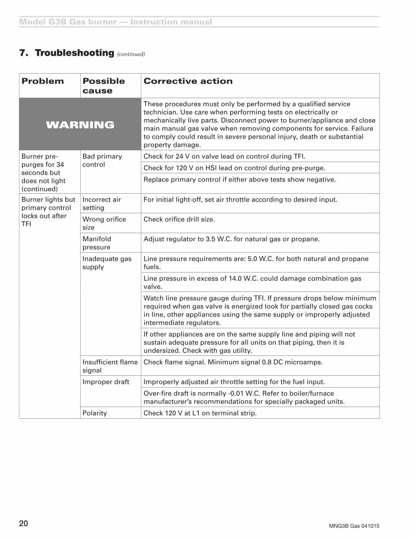
7. Troubleshooting (continued)
Problem Possible cause
Corrective action
WARNING
These procedures must only be performed by a qualified service technician. Use care when performing tests on electrically or mechanically live parts. Disconnect power to burner/appliance and close main manual gas valve when removing components for service. Failure to comply could result in severe personal injury, death or substantial property damage.
Burner pre-purges for 34 seconds but does not light (continued)
Bad primary control
Check for 24 V on valve lead on control during TFI.
Check for 120 V on HSI lead on control during pre-purge.
Replace primary control if either above tests show negative.
Burner lights but primary control locks out after TFI
Incorrect air setting
For initial light-off, set air throttle according to desired input.
Wrong orifice size
Check orifice drill size.
Manifold pressure
Adjust regulator to 3.5 W.C. for natural gas or propane.
Inadequate gas supply
Line pressure requirements are: 5.0 W.C. for both natural and propane fuels.
Line pressure in excess of 14.0 W.C. could damage combination gas valve.
Watch line pressure gauge during TFI. If pressure drops below minimum required when gas valve is energized look for partially closed gas cocks in line, other appliances using the same supply or improperly adjusted intermediate regulators.
If other appliances are on the same supply line and piping will not sustain adequate pressure for all units on that piping, then it is undersized. Check with gas utility.
Insufficient flame signal
Check flame signal. Minimum signal 0.8 DC microamps.
Improper draft Improperly adjusted air throttle setting for the fuel input.
Over-fire draft is normally -0.01 W.C. Refer to boiler/furnace manufacturer’s recommendations for specially packaged units.
Polarity Check 120 V at L1 on terminal strip.

Model G3B Gas burner — Instruction manual
MNG3B Gas 041015 21
8. Dimensions and mounting information
Figure 10 Dimensional data
Mounting burner to appliance
The universal flange supplied with G3B Gas burners is intended only for firing chambers with negative overfire pressure. The G3B burner must not be installed on a product that operates with a pressurized combustion chamber. Failure to comply could result in severe personal injury, death or substantial property damage.
Prepare the burner opening on the front of the appliance as shown in Figure 11. See page 6 to determine the location of the flange on the burner air tube. Tighten the flange locking screws firmly.
Figure 11 Universal flange mounting
Model G3B Gas burner — Instruction manual
MNG3B Gas 04101522
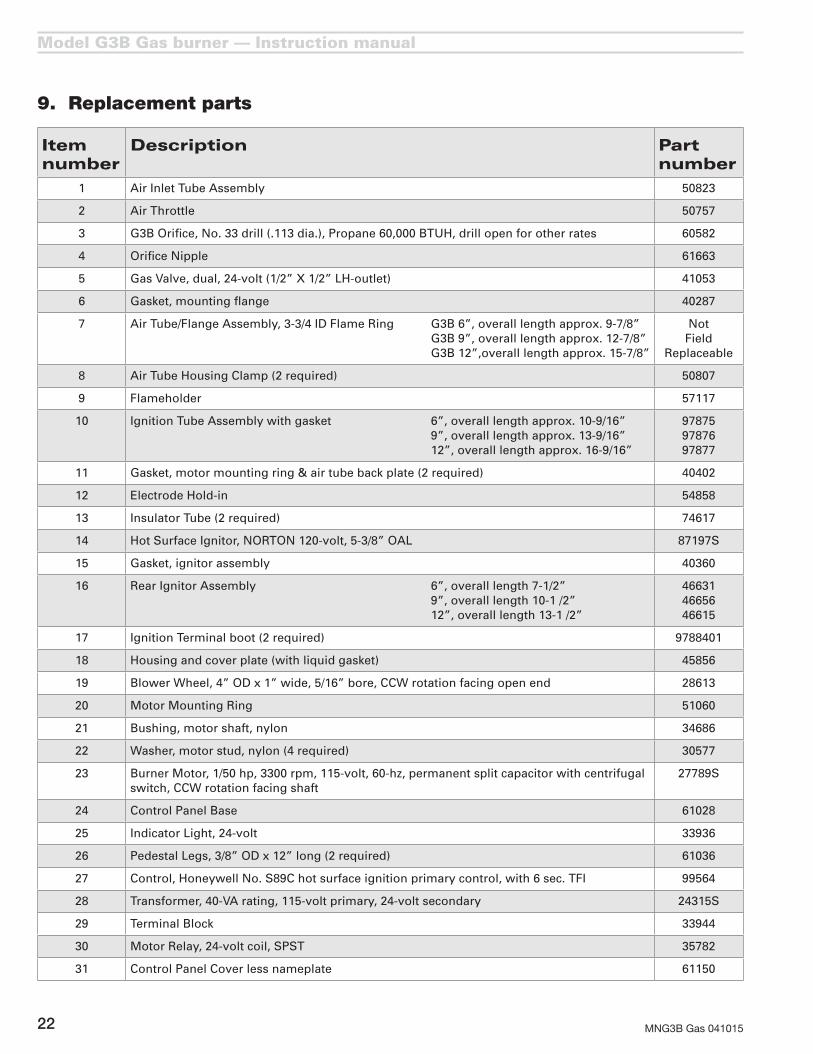
9. Replacement parts
Item number
Description Part number
1 Air Inlet Tube Assembly 50823
2 Air Throttle 50757
3 G3B Orifice, No. 33 drill (.113 dia.), Propane 60,000 BTUH, drill open for other rates 60582
4 Orifice Nipple 61663
5 Gas Valve, dual, 24-volt (1/2” X 1/2” LH-outlet) 41053
6 Gasket, mounting flange 40287
7 Air Tube/Flange Assembly, 3-3/4 ID Flame Ring G3B 6”, overall length approx. 9-7/8” G3B 9”, overall length approx. 12-7/8” G3B 12”,overall length approx. 15-7/8”
Not Field
Replaceable
8 Air Tube Housing Clamp (2 required) 50807
9 Flameholder 57117
10 Ignition Tube Assembly with gasket 6”, overall length approx. 10-9/16” 9”, overall length approx. 13-9/16” 12”, overall length approx. 16-9/16”
978759787697877
11 Gasket, motor mounting ring & air tube back plate (2 required) 40402
12 Electrode Hold-in 54858
13 Insulator Tube (2 required) 74617
14 Hot Surface Ignitor, NORTON 120-volt, 5-3/8” OAL 87197S
15 Gasket, ignitor assembly 40360
16 Rear Ignitor Assembly 6”, overall length 7-1/2” 9”, overall length 10-1 /2” 12”, overall length 13-1 /2”
466314665646615
17 Ignition Terminal boot (2 required) 9788401
18 Housing and cover plate (with liquid gasket) 45856
19 Blower Wheel, 4” OD x 1” wide, 5/16” bore, CCW rotation facing open end 28613
20 Motor Mounting Ring 51060
21 Bushing, motor shaft, nylon 34686
22 Washer, motor stud, nylon (4 required) 30577
23 Burner Motor, 1/50 hp, 3300 rpm, 115-volt, 60-hz, permanent split capacitor with centrifugal switch, CCW rotation facing shaft
27789S
24 Control Panel Base 61028
25 Indicator Light, 24-volt 33936
26 Pedestal Legs, 3/8” OD x 12” long (2 required) 61036
27 Control, Honeywell No. S89C hot surface ignition primary control, with 6 sec. TFI 99564
28 Transformer, 40-VA rating, 115-volt primary, 24-volt secondary 24315S
29 Terminal Block 33944
30 Motor Relay, 24-volt coil, SPST 35782
31 Control Panel Cover less nameplate 61150

Model G3B Gas burner — Instruction manual
MNG3B Gas 041015 23
9. Replacement parts (continued)

Model G3B Gas burner — Instruction manual
MNG3B Gas 04101524