INSTRUCTION MANUAL PAULISTINHA P-56 · C B ’ C’ Securely ... PAULISTINHA P-56 Warning! 70 mm...
16
PAULISTINHA P-56 Wing Span Wing Area Flying Weight Fuselage Length 71.0 in / 1800 mm 698 sq in / 45.0 sq dm 5.5 lbs / 2500 g 47.0 in / 1200 mm Specifications Requires: 0.40-0.46 cu. in. displacement 2-stroke 0.52-0.56 cu. in. displacement 4-stroke 4 - channel radio w/ 5 standard servos INSTRUCTION MANUAL FACTORY PRE-FABRICATED ALMOST-READY-TO-FLY(ARF)SERIES MADE IN CHINA * Specifications are subject to change without notice.* Warning ! This model is not a toy. It is designed for maximum performance. Please seek advice if one is not familiar with this kind of electric powered precision model. Operating this model without prior preparation may cause injuries. Remember, safety is the most important thing. Always keep this instruction manual at hand for quick reference. The World Models Manufacturing Co., Ltd. www.theworldmodels.com A321PO26781107
Transcript of INSTRUCTION MANUAL PAULISTINHA P-56 · C B ’ C’ Securely ... PAULISTINHA P-56 Warning! 70 mm...

PAULISTINHA P-56
Wing SpanWing AreaFlying WeightFuselage Length
71.0 in / 1800 mm698 sq in / 45.0 sq dm5.5 lbs / 2500 g47.0 in / 1200 mm
Specifications
Requires: 0.40-0.46 cu. in. displacement 2-stroke 0.52-0.56 cu. in. displacement 4-stroke 4 - channel radio w/ 5 standard servos
INSTRUCTION MANUAL
FACTORY PRE-FABRICATEDALMOST-READY-TO-FLY(ARF)SERIES
MADE IN CHINA
* Specifications are subject to change without notice.*
Warning ! This model is not a toy.It is designed for maximum performance. Please seek advice if one is not familiar with this kindof electric powered precision model. Operating this model without prior preparation may causeinjuries. Remember, safety is the most important thing. Always keep this instruction manual athand for quick reference.
The World ModelsManufacturing Co., Ltd.www.theworldmodels.com
A321PO26781107

BEFORE YOU BEGIN
INDEXBEFORE YOU BEGIN
PARTS LIST
ASSEMBLY
SAFETY PRECAUTIONS
P.1
P.2
P.3 - 11
P.11
Read through the manual before you begin, so you will have an overall idea of what to do.
Check all parts. If you find any defective or missing parts contact your local dealer. PleaseDRY FIT and check for defects for all parts that will require CA or Epoxy for final assembly.Any parts you find to be defective after the gluing process may be difficult to remove forwarranty replacement. The manufacturer will replace any defective parts, but will not extendto the parts that are good before gluing to defective parts during assembly. Warranty willnot cover any parts modified by customer.
Symbols used throughout this instruction manual comprise of the following :-
1
2
3
P.1
3mm
Do not overlook this symbol!
Cut off shaded portion.Peel off shaded portioncovering film.
Pay close attention here!
Pierce the shaded portioncovering film.
Must be purchased separately!
Drill holes with the specifieddiameter (here: 3mm).
Ensure smooth non-bindingmovement while assembling.
Apply instant glue(C.A.glue, super glue.)
Assemble left and rightsides the same way.
Apply epoxy glue.
Apply thread locker
Warning!
PAULISTINHA P-56
A321PO26781107
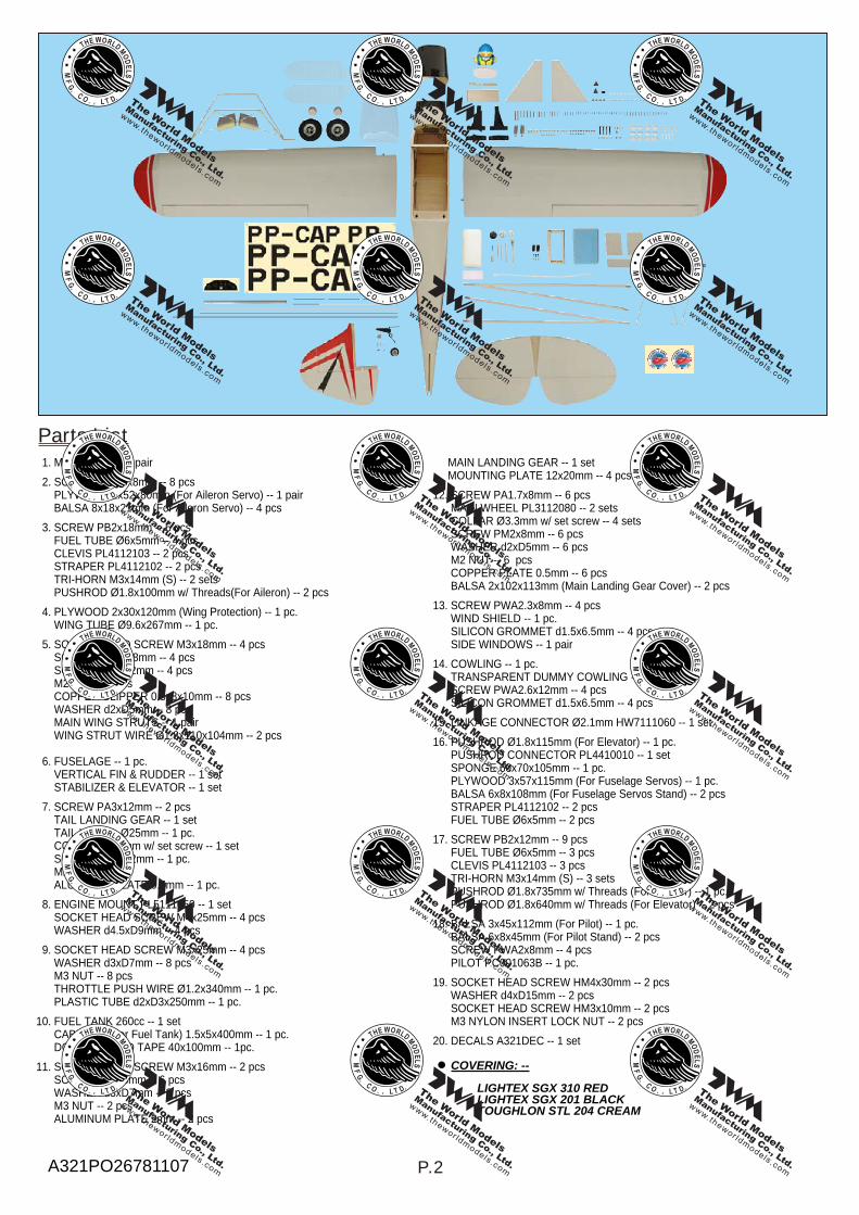
Parts List
P.2
COVERING: --
LIGHTEX SGX 310 RED LIGHTEX SGX 201 BLACK TOUGHLON STL 204 CREAM
1. MAIN WING -- 1 pair 2. SCREW PWA2x8mm -- 8 pcs PLYWOOD 2x52x80mm (For Aileron Servo) -- 1 pair BALSA 8x18x21mm (For Aileron Servo) -- 4 pcs 3. SCREW PB2x18mm -- 6 pcs FUEL TUBE Ø6x5mm -- 4 pcs CLEVIS PL4112103 -- 2 pcs STRAPER PL4112102 -- 2 pcs TRI-HORN M3x14mm (S) -- 2 sets PUSHROD Ø1.8x100mm w/ Threads(For Aileron) -- 2 pcs 4. PLYWOOD 2x30x120mm (Wing Protection) -- 1 pc. WING TUBE Ø9.6x267mm -- 1 pc. 5. SOCKET HEAD SCREW M3x18mm -- 4 pcs SCREW PWA2x8mm -- 4 pcs SCREW PM2x12mm -- 4 pcs M2 NUT -- 4 pcs COPPER CLIPPER 0.5x8x10mm -- 8 pcs WASHER d2xD5mm -- 8 pcs MAIN WING STRUTS -- 1 pair WING STRUT WIRE Ø1.8x110x104mm -- 2 pcs
6. FUSELAGE -- 1 pc. VERTICAL FIN & RUDDER -- 1 set STABILIZER & ELEVATOR -- 1 set 7. SCREW PA3x12mm -- 2 pcs TAIL LANDING GEAR -- 1 set TAIL WHEEL Ø25mm -- 1 pc. COLLAR Ø2.1mm w/ set screw -- 1 set SCREW PM2x12mm -- 1 pc. M2 NUT -- 1 pc. ALUMINUM PLATE 0.5mm -- 1 pc. 8. ENGINE MOUNT PL5111050 -- 1 set SOCKET HEAD SCREW M4x25mm -- 4 pcs WASHER d4.5xD9mm -- 4 pcs 9. SOCKET HEAD SCREW M3x25mm -- 4 pcs WASHER d3xD7mm -- 8 pcs M3 NUT -- 8 pcs THROTTLE PUSH WIRE Ø1.2x340mm -- 1 pc. PLASTIC TUBE d2xD3x250mm -- 1 pc. 10. FUEL TANK 260cc -- 1 set CABLE TIE(For Fuel Tank) 1.5x5x400mm -- 1 pc. DOUBLE-SIDED TAPE 40x100mm -- 1pc. 11. SOCKET HEAD SCREW M3x16mm -- 2 pcs SCREW PA3x8mm -- 6 pcs WASHER d3xD7mm -- 2 pcs M3 NUT -- 2 pcs ALUMINUM PLATE 2mm -- 2 pcs
MAIN LANDING GEAR -- 1 set MOUNTING PLATE 12x20mm -- 4 pcs 12. SCREW PA1.7x8mm -- 6 pcs MAIN WHEEL PL3112080 -- 2 sets COLLAR Ø3.3mm w/ set screw -- 4 sets SCREW PM2x8mm -- 6 pcs WASHER d2xD5mm -- 6 pcs M2 NUT -- 6 pcs COPPER PLATE 0.5mm -- 6 pcs BALSA 2x102x113mm (Main Landing Gear Cover) -- 2 pcs 13. SCREW PWA2.3x8mm -- 4 pcs WIND SHIELD -- 1 pc. SILICON GROMMET d1.5x6.5mm -- 4 pcs SIDE WINDOWS -- 1 pair 14. COWLING -- 1 pc. TRANSPARENT DUMMY COWLING -- 1 pc. SCREW PWA2.6x12mm -- 4 pcs SILICON GROMMET d1.5x6.5mm -- 4 pcs 15. LINKAGE CONNECTOR Ø2.1mm HW7111060 -- 1 set 16. PUSHROD Ø1.8x115mm (For Elevator) -- 1 pc. PUSHROD CONNECTOR PL4410010 -- 1 set SPONGE 60x70x105mm -- 1 pc. PLYWOOD 3x57x115mm (For Fuselage Servos) -- 1 pc. BALSA 6x8x108mm (For Fuselage Servos Stand) -- 2 pcs STRAPER PL4112102 -- 2 pcs FUEL TUBE Ø6x5mm -- 2 pcs 17. SCREW PB2x12mm -- 9 pcs FUEL TUBE Ø6x5mm -- 3 pcs CLEVIS PL4112103 -- 3 pcs TRI-HORN M3x14mm (S) -- 3 sets PUSHROD Ø1.8x735mm w/ Threads (For Rudder) -- 1 pc. PUSHROD Ø1.8x640mm w/ Threads (For Elevator) -- 2 pcs 18. BALSA 3x45x112mm (For Pilot) -- 1 pc. BALSA 6x8x45mm (For Pilot Stand) -- 2 pcs SCREW PWA2x8mm -- 4 pcs PILOT PC001063B -- 1 pc. 19. SOCKET HEAD SCREW HM4x30mm -- 2 pcs WASHER d4xD15mm -- 2 pcs SOCKET HEAD SCREW HM3x10mm -- 2 pcs M3 NYLON INSERT LOCK NUT -- 2 pcs 20. DECALS A321DEC -- 1 set
A321PO26781107

PWA2x8mm
Plywood2x52x80mm
1mm
2mm
Balsa8x18x21mm
Make a slot into the hatch for the servo horn to come out.
1mm
Aileron Servo2
PWA2x8mm Screw8
Aileron Servo3
P.3
Ø1mm pilot holes for The World Models tri-horn are pre-drilled.Please look for pin-hole marks at under side of control surfaces.
TWM PL8210010CLEVIS WRENCH
Main Wing1Aileron Servo Lead
PB2x18mm
Fuel Tube Ø6x5mm
Fuel Tube Ø6x5mm
Straper
ClevisPB2x18mm Screw
6Tri-horn
M3x14mm (S)
Pre-g lued
Bottom View
Bottom View
Bottom View
A321PO26781107

Vertical Fin / Horizontal Stabilizer6
Make sure vertical fin and stabilizer are at right angles.
Temporary install the main wing, adjust leveling of the stabilizer to make it as parallel to the main wing as possible.
Wing Struts5
Thread Locker
Main Wing4
Plywood2x30x120mm
Aluminum Tube
Ø9.6x267mm
Join the wing halves by using the aluminium tube suppliedStrengthen both holes for the screws with a piece of plywood.
P.4
Bottom View
B B'
B=B'
(Stabilizer)
(Main Wing) Pre-glued
Pre-glued
90
M3x18mm Socket Head Screw
M3x18mm Socket Head Screw
PM2x12mm ScrewPM2x12mm
d2xD5mm Washer
4
4
8
4
PWA2X8mm Screw
PWA2X8mm
4
M2 Nut
d2xD5mm Washer
M2 Nut
Copper Clipper0.5x8x10mm
95mm
189mm
286.5mm
189mm95mm
A321PO26781107

Tail Landing Gear7
PA3x12mm Screw
3mm Set Screw
3mm Set Screw
2.1mm Collar
PM2x12mm Screw
PA3x12mmPM2x12mm
2
1
1
1M2 Nut
1
Engine Mount8
M4x25mmSocket Head Screw
M4x25mmSocket Head Screw
4
4
d4.5xD9mm Washer
Engine MountPL5111050
Engine9
M3x25mmSocket Head Screw
M3x25mmSocket Head Screw
8d3xD7mm Washer
d3xD7mmWasher
d3xD7mmWasher
8
M3 Nut
M3 Nut
Lead the 1.2mm throttle rod through theplastic tube and attach the throttle rodto the throttle lever on the engine.
Install Engine position
115mm4.53in
FireWall
d4.5xD9mmWasher
P.5A321PO26781107
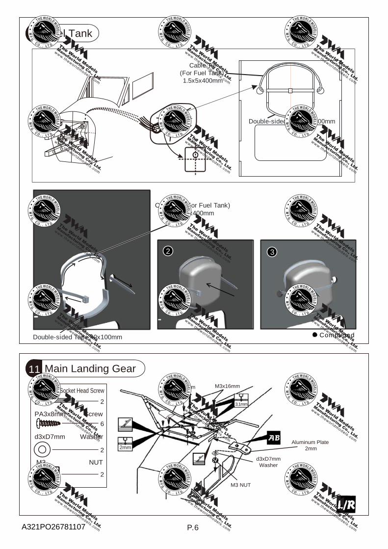
Fuel Tank10
Main Landing Gear11
M3x16mm Socket Head Screw
PA3x8mm Screw
d3xD7mm Washer
2
6
2
2
2mm
3.1mm
Aluminum Plate 2mm
P.6
M3 NUT
PA3x8mm
d3xD7mmWasher
M3 NUT
M3x16mm
UP
1
3
Cable Tie (For Fuel Tank)1.5x5x400mm
Completed
Double-sided Tape 40x100mm
Double-sided Tape 40x100mm
Cable Tie(For Fuel Tank)1.5x5x400mm
2
Fuel Tank
260cc
A321PO26781107

P.7
Canopy13
PWA2.3x8mm Screw
d1.5x6.5mm Silicon Grommet
d1.5x6.5mmSilicon Grommet
4
4
PWA2.3x8mm
Securely glue the windows to the fuselage.
Cowling14
PWA2.6x12mm Screw
PWA2.6x12mm
d1.5x6.5mm Silicon Grommet
d1.5x6.5mmSilicon Grommet
4
4
Trim the cowling for the engine head to project.
1.5mm1.5mm
Please refer to the attached sheet for usage of the transparent 3D template.First insert the grommet to the cowling then apply screw.
CowlingFuselage
d1.5x6.5mmSilicon Grommet
PWA2.6x12mm
12
2.1mmPM2x8mm
Copper Clipper
PM2x8mm Screw
PA1.7X8mm Screw
d2xD5mm Washer
d2xD5mmWasher
d2xD5mmWasher
6
6
6
6
43mm Set Screw
43.3mm w/set Collar
3.3mmw/set Collar
PM2x8mm
PA1.7X8mm
Main Landing Gear
M2 Nut
M2 Nut
A321PO26781107

Rudder & Elevator Pushrod17
P.8
PB2x12mm Screw9
Set the pushrods as shown in the diagram.
Ø1mm pilot holes for The World Models tri-horn are pre-drilled. Please look for pin-hole marks at under side of control surfaces.
TWM PL8210010CLEVIS WRENCH
Bot tom View
RudderPushrod
ElevatorPushrodPB2x12mm
RudderTri-horn
ElevatorTri-horn
Tri-horn3x14mm
Clevis
PB2x12mm
Tri-hornM3x14mm (S)
Fuel Tube Ø6x5mm
Fuel Tube Ø6x5mm
Clevis
Servo Set15
1
13x3mm Set Screw
Linkage Connector
M2 Nut
2mm Washer1
2
Please refer to the attached sheet for linkage connector installation.
Throttle Pushwire
3mm
Throttle Servo.2mm
2mmWasher
M2 Nut
2mmWasher
Radio Equipment16 Install and arrange the servos as shown in the diagram.
Fuel Tank
Receiver
Battery
Straper
RudderØ1.8x735mm
Pushrod
Fuel TubeØ6x5mm
Elevator PushrodØ1.8x640mmElevator Servo
Rudder Servo
Throttle PushrodØ1.2x340mm
KM 2x8mm
M2 Nut
Elevator PushrodØ1.8x115mm
Elevator Servo
PushrodConnector
J2(Pushrod Ø1.8x640)
J1(Pushrod Ø1.8x115) J1
J2
Throttle Servo
A321PO26781107

HM4x30mm
d4xD15mmWasher
HM3x10mm
M3 Nylon Insert Lock Nut
3mm
19 Main Wing / Wing Struts
HM4x30mmSocket Head Screw
d4xD15mm Washer2
2HM3x10mmSocket Head Screw
M3 Nylon Insert Lock Nut
2
2
P.9
Cockpit18
PWA2x8mm Screw
PWA2x8mm
4
PC001063B
Balsa3x45x112mm
Balsa6x8x45mm
1.5mm
A321PO26781107

P.10
Wing Setting20
A A’
BC
B’C’
Securely attach themain wing
A=A’ B=B’ C=C’
A321PO26781107

# First time flyer should never fly by himself / herself. Assistance from experienced flyer is absolutely necessary.
# Pre-flight adjustment must be done before flying, it is very dangerous to fly a badly pre-adjusted aircraft.
# is specially designed to be powered by 2C 0.40-0.46 or 4C 0.52-0.56 engine, using a more powerful engine does not mean better performance. In fact, over powered engine may cause severe damage and injuries.
# Make sure the air field is spacious, never fly the plane too close to people and never get too close to a running propeller.
# If you find wrinkles on the covering as a result of weather changes, you can use hot iron to remove the wrinkles. Please begin with lower temperature setting and gradually raise the temperature until the wrinkles are gone. Too hot an iron may damage the covering. Don't use hot iron near the seams or edges, hot iron will melt the glue and shrink the covering at the same time, causing the seams to pull away.
# Check and re-tighten up all factory assembled screws, use thread locker if necessary.
Control Throws21
Rudder
Elevator
Aileron
25mm25mm
20mm20mm
10m
http://www.theworldmodels.com/para/instruction/instructionManuals.php
m10mm
Adjust the control throws as shown inthe diagram. These throws are good for general flying. You can adjust accordingto your personal preference.
C.G.22 The ideal C.G. position is 70mm (2.76 in) behindthe leading edge measured at where the wingmeets the fuselage. In order to obtain the C.G.specified, add weight to the fuselage or movethe battery position. Check the C.G. before flying.
P.11
Important Safety Precautions
PAULISTINHA P-56
Warning!
70 mm2.76 in
A321PO26781107

This transparent 3D templateis used for position guidanceof the actual cutting of thepre-painted cowling.
Usage of the transparent 3D template
Simply cut the transparent 3D template to fit your engine and exhaust pipe, then slide onto the actual cowling and use as template to mark the openings required for final cutting.
1 2
3 4
A321PO26781107

Product Registration Form (US Customers)
We would like to share with you any relevant information regarding your model, includingproduct news and free upgrade parts when applicable. Please fill in the following and send toAirBorne Models, 4749-K, Bennett Drive, Livermore, CA 94551 USA.
1. Name:______________________________________________
2. Address:____________________________________________
3. Phone #:____________________ E-mail:__________________
4. Model:______________________________________________
Wing QC#__________ Fuselage QC# _______________________(QC numbers are stamped on wing and fuselage)
5. Date of Purchase:_____________________________________
6. Store Name: _________________________________________
Please call AirBorne Models at 925 371 0922 for any assistance in filling this form.Thank you very much for purchasing our product.
Drill 2mm hole at servo horn.Insert linkage connectorinto servo horn.
Make sure shoulder ofscrew is cleared fromservo horn.Add washer to reduceplay if necessary.
Shoulder
Tighten up the round nutagainst the shoulder. ApplyCA or permanent threadlocker.
After fastening the round nut, make sure thatthe linkage connector can rotate freely.
LINKAGE CONNECTORHW7111050 & HW7111060
A321PO26781107

Fuel Filter
Code No. Size Package
Code No. Size PackageCode No. Size Package
Code No. Size Package
Code No. Size Package
Code No. Size Package
Code No SV4031
KP0041300
Special tool for clevis installation.Suitable for standard and small(EP)clevis.
Large ClevisSmall Clevis
180mm Extension
MS9111450 600 x 240 x 350mm 1 pc
A321PO26781107

The World ModelsManufacturing Co., Ltd.www.theworldmodels.com
A321PO26781107