INSTRUCTION MANUALOnce the hand control is powered on and the “Initialization” process is...
46
INSTRUCTION MANUAL SynScan TM SSHCV3-F-141031V1-EN Copyright © Sky-Watcher SynScan TM
Transcript of INSTRUCTION MANUALOnce the hand control is powered on and the “Initialization” process is...
INSTRUCTION MANUALSynScanTM
SSHCV3-F-141031V1-EN
Copyright © Sky-Watcher
SynScan TM

2
PART I : INTRODUCTION
PART II : INITIALIZATION
PART III : ALIGNMENT
PART IV : SYNSCAN MENU TREE
PART V : LOCATING OBJECTS
PART VI : CONFIGURE THE TELESCOPE MOUNT
CONTENT
1.1 Outline and Interface .......................................................................................... 41.2 Connecting to a Telescope Mount ...................................................................... 41.3 Slew the Mount with the Direction Keys .............................................................. 41.4 SynScan Hand control’s Operating Modes ......................................................... 5
2.1 Setup Home Position of the Telescope Mount ..................................................... 72.2 Initialize the Hand Control .................................................................................. 7
3.1 Choosing an Alignment Method .........................................................................113.2 Aligning to Alignment Stars ...............................................................................113.3 Alignment Method for Equatorial Mounts ..........................................................113.4 Alt-Azimuth Mounts using Brightest Star Alignment Method ............................123.5 Alt-Azimuth Mounts using 2-Star Alignment Method ........................................153.6 Tips for Improving Alignment Accuracy .............................................................163.7 Comparison of Alignment Methods ....................................................................16
4.1 Menu Structure .................................................................................................. 184.2 Accessing Menus ..............................................................................................194.3 Short-cut Keys ....................................................................................................19
5.1 Locating Messier Objects ................................................................................. 205.2 Locating NGC and IC Objects .......................................................................... 215.3 Locating Planets and the Moon ........................................................................ 215.4 Locating Caldwell Objects ................................................................................ 215.5 Locating SAO Stars .......................................................................................... 225.6 Locating Named Stars, Double Stars, and Variable Stars ............................... 225.7 Deep Sky Tour ................................................................................................... 235.8 User-Defined Objects ........................................................................................ 23
6.1 Choosing Tracking Speed ...............................................................................256.2 Backlash Compensation ...................................................................................256.3 Setting the Altitude Axis Slewing Limits .........................................................256.4 Enable/Disable Auxiliary Encoder ....................................................................266.5 Setting Autoguider Speed ................................................................................266.6 Setting Flipping Mode .........................................................................................26
PART VII : CONFIGURE THE HAND CONTRL7.1 Display, Keypad, and Beeper ............................................................................... 277.2 Alignment Star Filter ........................................................................................... 277.3 Sorting Method of the Alignment Star List ......................................................... 27
Basic Operations
Intermediate Operations

3
PART VIII : AUXILIARY FUNCTIONS
PART IX : CONNECTING TO A COMPUTER
PART X : UPDATING FIRMWARE
PART XI : ADVANCED FUNCTIONS
PART XII : USING A SYNSCAN GPS MODULE
APPENDIX I : ELIMINATING CONE ERROR ...................................................... 43
APPENDIX II : SYNSCAN SELF-DIAGNOSIS ..................................................... 44
APPENDIX III : SCHEMATIC OF THE PORTS .................................................... 45
APPENDIX IV : SPECIFICATIONS ................................................................ 45
CONTENT
9.1 Working with Astronomical Applications .............................................................. 319.2 PC Direct Mode ..................................................................................................31
12.1 Initialization of the Hand control with a SynScan GPS Module .............................. 4212.2 Checking GPS Information ................................................................................. 42
10.1 Hardware Requirements .................................................................................... 32 10.2 Preparation ........................................................................................................ 3310.3 Updating Firmware ............................................................................................. 3410.4 Trouble Shooting ............................................................................................... 33
8.1 Editing Date, Time, Coordinates, Time Zones, and Daylight Saving Time ......... 288.2 Re-aligning the Mount ........................................................................................ 288.3 Show Position ................................................................................................. 288.4 Show Time and Local Sidereal Time ............................................................ 288.5 Display Version Information ........................................................................... 288.6 Display Temperature ..................................................................................... 298.7 Display Power Voltage ................................................................................... 298.8 Display Polaris Position .................................................................................. 298.9 Display Polar Alignment Error ........................................................................ 298.10 Changing Polar Scope Illumination Level ........................................................... 298.11 Identifying Objects ............................................................................................. 298.12 Synchronizing Encoders .................................................................................... 30
11.1 Parking Telescope .............................................................................................. 3411.2 Pointing Accuracy Enhancement ....................................................................... 3511.3 Polar Alignment without Polar Scope ................................................................. 3611.4 Camera Control .................................................................................................. 3711.5 Periodic Error Correction (PEC) for EQ Mount ..................................................... 3911.6 Calibrating Auto-Home Offset ............................................................................ 4011.7 Setting Cone Error and Non-Perpendicular Error .............................................. 4011.8 Astronomical Time-Lapse Photography ...........................................................41
Advanced Operations
Appendix

4
PART I : INTRODUCTION
Mount Port: Connects to a Sky-Watcher telescope mount. The hand control can get power supply from the mount via this port.
Multi-Purpose Port: Connects to an external device such as a com-puter, a GPS module, a camera, etc.
LCD Display Screen: It can display two lines of text, 16 characters per line. The contrast and the brightness of the red backlight are ad-justable.
Power Port: Connects to a power supply for standalone (not connect-ed to a telescope mount) use of the hand control. It accepts a plug with a 5.5mm O.D. and a 2.0mm I.D.
Buttons: ESC, SETUP, ENTER, directional, number/shortcut keys, and scroll keys.
A SynScan hand control and its interfaces are shown in Fig. 1.1
1.1 Outline and Interface
1.2 Connecting to a Telescope Mount
Fig. 1.1
Connect the 8-pin (RJ-45) “Mount” port of the hand control to the “Hand Control” port on a Sky-Watcher mount using an appropriate cable. The table below lists the “Hand Control” ports on different Sky-Watcher mounts.
Mount Model Hand control Port “Hand Control” Port on MountEQ6 Pro
8-pin RJ-45
D-sub 9 MaleHEQ5 Pro, EQ5 Pro, EQ3 Pro, AZ-EQ6 GT, EQ8
8-pin RJ-45
All Alt-azimuth mounts 6-pin RJ-12
1.3 Slew the Mount with the Direction KeysIn many situations, users need to slew the mount at different speeds with the directional keys. Here are the guides for this operation:
5
PART I: INTRODUCTION
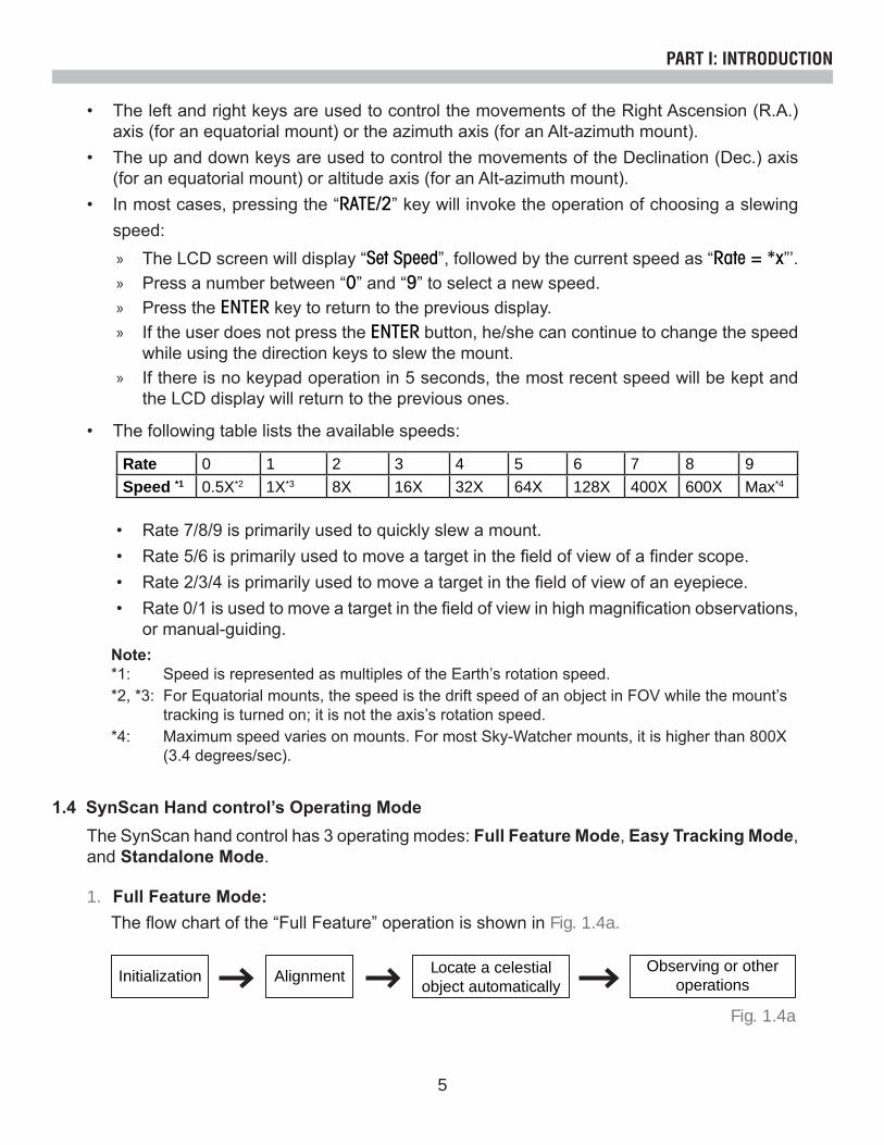
1. Full Feature Mode:The flow chart of the “Full Feature” operation is shown in Fig. 1.4a.
• The left and right keys are used to control the movements of the Right Ascension (R.A.) axis (for an equatorial mount) or the azimuth axis (for an Alt-azimuth mount).
• The up and down keys are used to control the movements of the Declination (Dec.) axis (for an equatorial mount) or altitude axis (for an Alt-azimuth mount).
• In most cases, pressing the “RATE/2” key will invoke the operation of choosing a slewing speed:
» The LCD screen will display “Set Speed”, followed by the current speed as “Rate = *x”’. » Press a number between “0” and “9” to select a new speed. » Press the ENTER key to return to the previous display. » If the user does not press the ENTER button, he/she can continue to change the speed
while using the direction keys to slew the mount. » If there is no keypad operation in 5 seconds, the most recent speed will be kept and
the LCD display will return to the previous ones.
• The following table lists the available speeds:
• Rate 7/8/9 is primarily used to quickly slew a mount.• Rate 5/6 is primarily used to move a target in the field of view of a finder scope.• Rate 2/3/4 is primarily used to move a target in the field of view of an eyepiece.• Rate 0/1 is used to move a target in the field of view in high magnification observations,
or manual-guiding.Note:*1: Speed is represented as multiples of the Earth’s rotation speed.*2, *3: For Equatorial mounts, the speed is the drift speed of an object in FOV while the mount’s tracking is turned on; it is not the axis’s rotation speed.*4: Maximum speed varies on mounts. For most Sky-Watcher mounts, it is higher than 800X (3.4 degrees/sec).
Rate 0 1 2 3 4 5 6 7 8 9Speed *1 0.5X*2 1X*3 8X 16X 32X 64X 128X 400X 600X Max*4
1.4 SynScan Hand control’s Operating ModeThe SynScan hand control has 3 operating modes: Full Feature Mode, Easy Tracking Mode, and Standalone Mode.
Initialization AlignmentObserving or other
operations
Fig. 1.4a
Locate a celestial object automatically
6
In Standalone mode, the hand control does not need to be connected to a mount.
Once the hand control is powered on and the “Initialization” process is complete, users may begin using the SynScan hand control to look up data of celestial objects and other information (ex. Sidereal time, Polaris’s orientation etc).
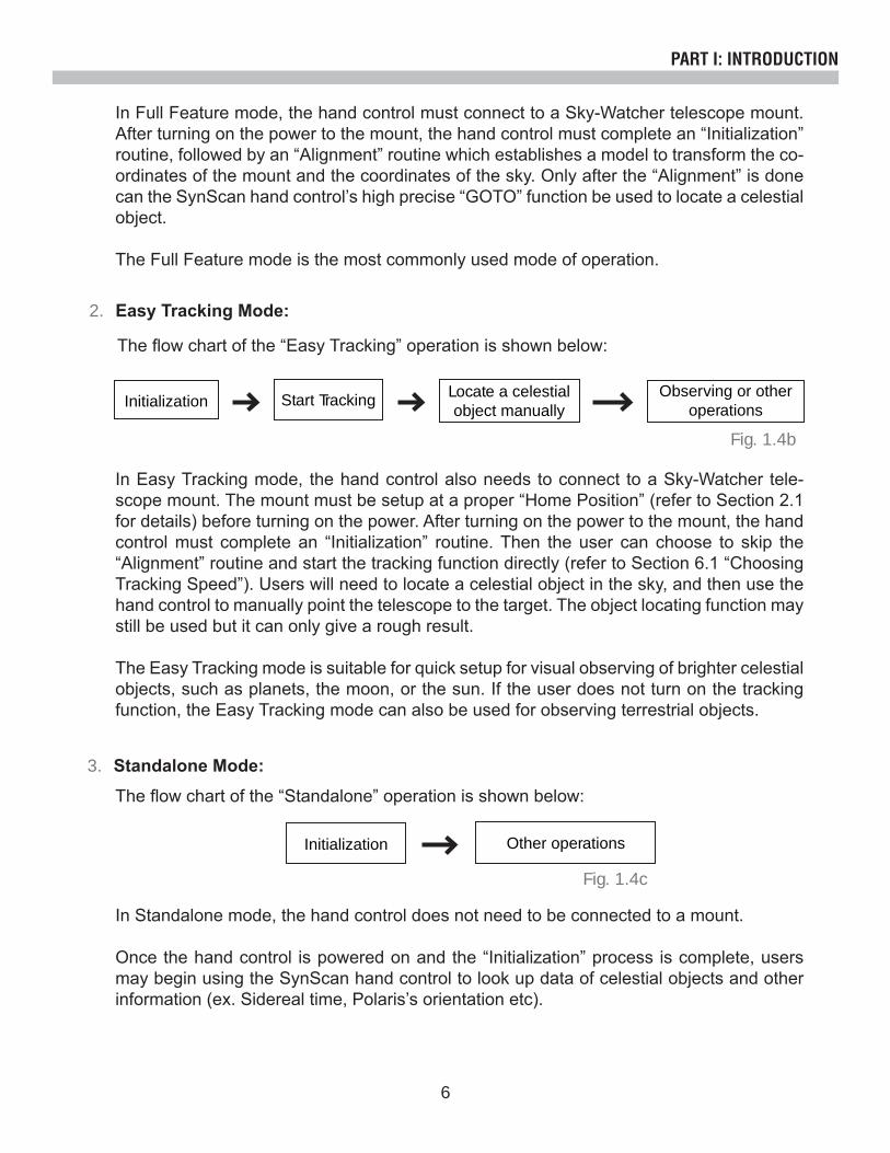
In Easy Tracking mode, the hand control also needs to connect to a Sky-Watcher tele-scope mount. The mount must be setup at a proper “Home Position” (refer to Section 2.1 for details) before turning on the power. After turning on the power to the mount, the hand control must complete an “Initialization” routine. Then the user can choose to skip the “Alignment” routine and start the tracking function directly (refer to Section 6.1 “Choosing Tracking Speed”). Users will need to locate a celestial object in the sky, and then use the hand control to manually point the telescope to the target. The object locating function may still be used but it can only give a rough result.
The Easy Tracking mode is suitable for quick setup for visual observing of brighter celestial objects, such as planets, the moon, or the sun. If the user does not turn on the tracking function, the Easy Tracking mode can also be used for observing terrestrial objects.
PART I: INTRODUCTION
The flow chart of the “Standalone” operation is shown below:
The flow chart of the “Easy Tracking” operation is shown below:
3. Standalone Mode:
2. Easy Tracking Mode:
In Full Feature mode, the hand control must connect to a Sky-Watcher telescope mount. After turning on the power to the mount, the hand control must complete an “Initialization” routine, followed by an “Alignment” routine which establishes a model to transform the co-ordinates of the mount and the coordinates of the sky. Only after the “Alignment” is done can the SynScan hand control’s high precise “GOTO” function be used to locate a celestial object.
The Full Feature mode is the most commonly used mode of operation.
Fig. 1.4b
Fig. 1.4c
Initialization Other operations
Initialization Start Tracking Locate a celestial object manually
Observing or other operations
7
PART II : INITIALIZATION
• Tripod head is leveled.• R.A. axis points towards the Northern Celestial Pole (in Northern Hemisphere) or the
Southern Celestial Pole (in Southern Hemisphere).• Counterweight rod is at its lowest position.• The telescope points towards the Northern Celestial Pole (in Northern Hemisphere) or
the Southern Celestial Pole (in Southern Hemisphere).
The mount should be setup as close as possible to the following home position:• Mount base is leveled.• The telescope tube is leveled and points towards the true north (not magnetic north).
Once the mount has been setup to the home position, a user can turn on the power to the mount and start the initialization process on the SynScan hand control. The following is the steps:
1. Home Position of an Equatorial Mount:
2. Home Position of an Alt-azimuth Mount:
2.1 Setup Home Position of the Telescope Mount
2.2 Initialize the Hand Control
Before powering on the telescope mount, it should be setup to a particular home position. The home position differs between an equatorial mount and an Alt-azimuth mount.
A SynScan hand control with a firmware version 3.32 or later supports both an equatorial mount and an alt-azimuth mount. It is able to detect the model of the mount to which it connects and select the appropriate operation mode accordingly.
For an equatorial/Alt-azimuth dual-mode mount, such as the AZ-EQ6 GT mount, the Syn-Scan hand control will request the user to choose the mount’s operating mode.
• The LCD screen will display “Operating Mode” in the first line.• Use the scrolling keys located at the bottom left and right of the keypad to choose be-
tween Equatorial mode (EQ Mode) and Alt-azimuth mode (AZ Mode).• Press ENTER to confirm the selection.
1. Selecting the Operation Mode of the Mount
The hand control will give a long beep and display the firmware version.• Press ENTER to proceed to the next step. Press ESC to return to the previous step.• Users can slew the mount with direction keys in this step.
2. Firmware Version Display
The hand control will display a warning message about the dangers of viewing the sun with a telescope.• Press ENTER to confirm you have read the warning messages and proceed to the next
step. Press ESC to return to the previous (firmware version display) step.• Users can slew the mount with direction keys in this step.
3. Warning Message Confirmation

8
PART II: INITIALIZATION
This step only applies to a mount with Auto-homing feature (such as the Sky-Watcher EQ8 Equatorial mount).• The LCD screen will display “Auto-Home?” in the first line, and display “1) YES 2) NO”
in the second line.• Press “2” to skip this step and proceed to the next step.• Press “1” to start the auto-homing routine on the mount. Once complete, the screen will
display “Home Position Established”. Press ENTER to proceed to the next step.• During auto-homing routine, pressing the ESC key will stop the mount’s movement. The
screen will display “Home Position NOT Established.” Press ENTER to proceed to the next step.
• After the home position is established, the LCD screen will display “Add DEC offset?” in the first line, and display “1)YES 2)NO” in the second line.
• Press “2” to skip this step and proceed to the next step.• Press “1” and then use the numeric keys and the LEFT/RIGHT directional keys to enter
offset (in degree) of the declination axis and then press ENTER key to confirm. The decli-nation axis will start slewing to the designated offset position. This function is designed for side-by-side dual telescopes setup.
Geographic CoordinatesThe LCD screen will display “Enter Location” in the first line, and display longitude and lat-itude in the second line.
• Press the numeric keys at the cursor position to fill the longitude and latitude digits.• Use the scroll keys to change east/west longitude or north/south latitude when the cur-
sor blinks on the corresponding characters (E/W for longitude, N/S for latitude).• Use the Left and Right direction keys to move the cursor.• Press the ENTER key to confirm the input and proceed to the next step. • Press the ESC key to return to Step 4 or Step 3.
4. Auto-homing
5. Setting Information of the Observing Site
Time ZoneThe LCD screen will display “Set Time Zone” in the first line, and display the current time zone in the second line.• Use the scroll keys to change the leading “+” or “-” sign when the cursor is on it. The “+”
sign is used for time zones in the Eastern Hemisphere (Europe, Africa, Asia, Oceania), while the “-” sign is used for time zones in the Western Hemisphere (North and South America).
• Press the numeric keys at the cursor position to fill the time zone digits.• Press the ENTER key to confirm the input and proceed to the next step. • Press the ESC key to return to the previous step.

9
Date, Time, Daylight Saving Time• When “Date: mm/dd/yyyy” is displayed, enter the current date in the indicated mm/dd/
yyyy format (i.e. 10/24/2012 for Oct.24,2012); press the ENTER key to confirm and pro-ceed to the next step. Press the ESC key to return to the “Geographic Coordinates” step.
• When “Enter Time” is displayed, enter the current local time in 24-hour format. (i.e. 18:30:00 for 6:30pm). Press the ENTER key to display the entered time in 12-hour for-mat. Press the ENTER key again to confirm and proceed to the next step. Press the ESC key to return to the previous step.
• When “Daylight Saving?” is displayed, use the scroll keys to select “Yes” or “No”. “YES” indicates the time entered in the previous step is daylight saving time, while “NO” indi-cates the time entered is in standard time. Press the ENTER key to confirm and proceed to the next step. Press the ESC key to return to the previous step.
PART II: INITIALIZATION
6. Display Polaris PositionThis step applies to an equatorial mount only.
• The LCD screen will display “Polaris Position in P.Scope = HH:MM”. It tells the orienta-tion of Polaris in the polar-scope’s FOV. User can imagine the large circle in the FOV of a polar-scope as a clock’s face with 12:00 at the top, and put Polaris at the “HH:MM” position of the large circle when using a polar-scope to do the polar alignment. Press ENTER key to confirm and proceed to the next step. Press ESC key to return to the pre-vious step.
• The LCD screen will display “Hour Angle of Polaris = HH:MM“. Press ENTER key to confirm and proceed to the next step. Press ESC key to return to the previous step.
Elevation (for atmospheric refraction compensation)The LCD screen will display “Set Elevation:” in the first line, and display the elevation in meters in the second line.• Use the scroll keys to change the leading “+” or “-” sign when the cursor is on it.• Press the numeric keys at the cursor position to fill the number of elevation in meters.• Press the ENTER key to confirm the input and proceed to the next step. • Press the ESC key to return to the previous step.
This is the last step in the hand control’s initialization process. The screen will display “Begin Alignment? 1) YES 2) NO” to ask the user to make a choice:
7. Starting Mount Alignment
Press “1” to start the alignment process The SynScan hand control will operate in Full Feature mode (refer to Section 1.4) after the alignment.

10
Press “2” to skip the alignment process. The SynScan hand control will enter standby mode.• Users may start the tracking functions (refer to Section 6.1), or use the GOTO function
(refer to PART V) to roughly locate celestial objects. Both operations will let the SynScan hand control work in the Easy Tracking mode (refer to Section 1.4 Step 2).
• Users can also start an alignment process (refer to Section 8.2) to let the SynScan hand control operate in Full Feature mode.
• Users may slew the mount with the direction keys to point the telescope to terrestrial targets for observing. The “User-Defined Objects” function (refer to Section 5.8) of the SynScan hand control is a useful tool for terrestrial observing.
PART II: INITIALIZATION

11
At the beginning of the alignment process, users are asked to choose an alignment method. The available alignment methods differ between the mount types, as listed below:• For an equatorial mount: 1-Start Alignment (1-Star Align.), 2-Star Alignment (2-Star
Align.) or 3-Star Alignment (3-Star Align.)• For an alt-azimuth mount: Brightest Star Alignment (Brightest Star) or 2-Star Alignment
(2-Star Align.)
Note: For a detailed description and comparison of each alignment method, please refer to Section 3.7.
Operation: • The LCD screen displays “Alignment:” in the first line.• Use the two scrolling keys to select an alignment method in the second line of the LCD
screen.• Press ENTER to confirm selection and proceed to the next step (Section 3.2).• Press ESC to skip the alignment process and enter standby mode.
3.1 Choosing an Alignment Method
PART III : ALIGNMENT
In this step, user will be asked to choose one or multiple alignment stars from a list provided by the SynScan hand control, and then control the mount to center the star(s) in the FOV of the telescope’s eyepiece. The SynScan hand control will then use the data collected in this process to transform between the mount coordinates and the sky coordinates.The operating steps of aligning to alignment stars may differ depending on the type of mount used, as well as the chosen alignment method. Users should read the following section which meets your mount and alignment method:
• Section 3.3: Alignment Method for Equatorial mounts.• Section 3.4: Alt-azimuth mounts using the Brightest Star Alignment method.• Section 3.5: Alt-azimuth mounts using the 2-Star Alignment method.
3.2 Aligning to Alignment Stars
3.3 Alignment Method for Equatorial Mounts
Aligning the 1st Star:1. The LCD screen displays “Choose 1st Star” in the first line. Use the scrolling keys to browse
through a list of star names and Press ENTER key to pick the one on the screen as the 1st
alignment star. The mount will then automatically slew and point the telescope towards the 1st alignment star in the sky.
2. After the mount stops, the hand control will give a long beep and display “Use dir. keys to center object”. Now the telescope should point rather closely to the 1st alignment star (gen-erally, in the FOV of the finder scope), and the mount’s tracking function is also turned on by the hand control to prevent the objects drift in the FOV of the telescope.

12
PART III : ALIGNMENT
3. Now users can use the direction keys to move the telescope to align with the 1st alignment star. That is, center the 1st alignment star in the FOV of the finder scope, and then center it in the FOV of the telescope’s eyepiece; press ENTER key to confirm centering of the star and proceed to the next step. Generally, users can use Rate 5 or 6 to center the star in the finder scope and use Rate 2 or 3 to center the star in the telescope’s eyepiece.
4. If the user has chosen 1-Star Alignment method before, the SynScan hand control will now display “Alignment Successful”. Press ENTER key to complete the alignment process and skip extra messages.
5. If the user has chosen 2-Star Alignment or 3-Star Alignment before, the SynScan hand control will then proceed to the next step.
The operation is the same as that of Aligning the 2nd Star.
1. While the mount is slewing during the alignment, users may press the ESC key to stop the mount. The hand control screen will display “Mount stopped. Press any key…”
2. Press any key and the SynScan hand control will ask the user to select another alignment star.
3. Press the ESC key again, the LCD screen will display “Exit Alignment? 1) YES 2) NO”. Press key 1 to exit the alignment process; press key 2 to go back to choose an alignment star.
1. Find the brightest stars in the current sky with naked eyes, and estimate its horizontal re-gion (orientation).
2. The hand control displays “Select Region”. Use the scroll keys to pick one of the eight re-gions shown in Fig 3.4a, which matches the horizontal region of the brightest star. Press ENTER to confirm selection and proceed to the next step.
3.4 Alt-Azimuth Mounts using Brightest Star Alignment Method
Aligning the 2nd Star:
Selecting and Aligning the 3rd Star:
Cancellation During Aligning Process:
1. Again, the SynScan hand control asks the user to choose and align a 2nd alignment star. The operation is the same as that of aligning the 1st alignment star.
2. If the user has chosen 2-Star Alignment before, the SynScan hand control will display “Alignment Successful” after confirmation of centering the 2nd alignment star.
3. Two seconds later, the LCD screen will display the polar-alignment offset of the mount. The “Mel” value is the offset in elevation, and the “Maz” value is the offset in azimuth. Press ENTER key to skip extra messages.
4. If the user has chosen 3-Star Alignment before, the SynScan hand control will then pro-ceed to the next step.
Aligning the 1st Star:

13
PART III : ALIGNMENT
3. The hand control will generate a list of the bright stars within the selected horizontal region. The list is sorted by the brightness of the star and with the brightest stars at the top of the list. Users can use the scroll keys to browse the list. An example of the screen display is shown in Fig. 3.4b.
• Only stars brighter than magnitude 1.5 will appear in the list. If there is no star brighter than magnitude 1.5 in the selected region, the hand control will display “No object found in this region.”
• If multiple bright stars appear in the list, users can identify the names of the stars in the real sky by matching the azimuth, altitude and magnitude provided by the SynScan hand control.
• Pick one of the star(s) (Generally the brightest one) as the 1st alignment star and press ENTER key to proceed to the next step. Press the ESC key to return to the previous step (“Select Region”).
Fig. 3.4a
Fig. 3.4b
NORTHEAST SKY
SO
UTHEAST SKY SOUTHWES
T SK
Y
NO
RTH
W
EST SKY
NORTHERN SKY
EA
ST
ER
N S
KY
SOUTHERN SKY
W
ES
TE
RN
SK
Y
N (0˚)
E (90˚)
S (180˚)
(225˚)
W (270˚)
(315˚)
(135˚)
(45˚)
1. CapellaNE 35.3
0.115.7
Magnitude
Altitude Angle
Star Name
Azimuth Angle
Orientation
Brightness Order

14
4. Now the screen will display “Point scope to RR ZZ.Z’ TT.T’ ”, which means point the telescope to RR region, the exact azimuth is ZZ.Z degree and the exact altitude is TT.T degree. Users can use the direction keys on the SynScan hand control to move the mount and point the telescope to the 1st alignment star selected in the previous step. Center the 1st alignment star in the FOV of the finder scope or the red dot finder, and then press ENTER key to pro-ceed to the next step.
PART III : ALIGNMENT
5. Now the screen will display “Ctr. Star NNNN”, where the NNNN is the name of the selected 1st alignment star. The star should have been in the FOV of the telescope. User can use the direction keys to center it in the eyepiece and then press the ENTER key to proceed to the next step.
Aligning the 2nd Star:
Cancellation During Aligning Process:
1. If the 1st alignment star is not a planet, the LCD screen will display “Choose 2nd Star”; other-wise, it will display “Choose 1st Star”.
2. Use the scrolling keys to browse through a list of star names and press ENTER key to pick the one on the screen as the 2nd alignment star. The mount will then automatically slew and point the telescope towards the 2nd alignment star in the sky.
3. After the mount stops, the hand control will give a long beep and will display “Use dir. keys to center object”. Now the telescope should point rather closely to the 2nd alignment star (generally, in the FOV of the finder scope).
4. Now users can use the direction keys to move the telescope to align with the 2nd alignment star. That is, center the 2nd alignment star in the FOV of the finder scope, and then center it in the FOV of the telescope’s eyepiece. Press ENTER key to confirm the centering of the star and proceed to the next step. Generally, users can use Rate 5 or 6 to center the star in finder scope and use Rate 2 or 3 to center the star in the telescope’s eyepiece.
5. If the 1st alignment star is not a planet, the SynScan hand control will now display “Align-ment Successful”. Press ENTER key to skip any extra message and complete the alignment process.
6. If the 1st alignment star is a planet, the SynScan hand control will display “Choose 2nd Star”. Repeat from Step 2 to complete the alignment process.
1. While the mount is slewing in alignment process, users may press the ESC key to stop the mount. The hand control screen will display “Mount stopped. Press any key…”
2. Press any key and the SynScan hand control will ask the user to select another alignment star.
3. Press the ESC key again; the LCD screen will display “Exit Alignment? 1) YES 2) NO”. Press key 1 to exit the alignment process; press key 2 to go back to choose an alignment star.
If the telescope has clutches on its axes, user can loosen the clutches to move the mount manually to point the telescope to the target.

15
PART III : ALIGNMENT
1. The LCD screen displays “Choose 1st Star” in the first line. Use the scrolling keys to browse through a list of star names and Press ENTER key to pick the one on the screen as the 1st alignment star.
2. Now the screen will display “Point scope to ZZZ.Z’ TT.T’ ”, which means point the telescope to the direction whose azimuth is ZZZ.Z degree and altitude is TT.T degree. This is also the direction of the selected 1st alignment star. Users can use the direction keys on the Syn-Scan hand control to move the mount to point the telescope to the star and center the star in the FOV of the finder scope or the red dot finder, and then press ENTER key to proceed to the next step.
� If the telescope has clutches on its axes, user can loosen the clutches to move the mount manually to point the telescope to the target.
3. Now the screen will display “Ctr. Star NNNN”, where the NNNN is the name of the selected 1st alignment star. The star should have been in the FOV of the telescope. User can use the direction keys to center it in the eyepiece and then press the ENTER key to proceed to the next step.
3.5 Alt-Azimuth Mounts using 2-Star Alignment MethodAligning the 1st Star:
Aligning the 2nd Star:1. The LCD screen displays “Choose 2nd Star”. Use the scrolling keys to browse through a list
of star names and Press ENTER key to pick the one on the screen as the 2nd alignment star. The mount will then automatically slew and point the telescope towards the 2nd alignment star in the sky.
2. After the mount stops, the hand control will give a long beep and will display “Use dir. keys to center object”. The telescope should point rather closely to the 2nd alignment star (generally, in the FOV of the finder scope.)
3. Now users can use the direction keys to move the telescope to align with the 2nd alignment star. To align, center the 2nd alignment star in the FOV of the finder scope, and then center it in the FOV of the telescope’s eyepiece. Press ENTER key to confirm centering of the star and proceed to the next step. Generally, users can use Rate 5 or 6 to center the star in finder scope and use Rate 2 or 3 to center the star in the telescope’s eyepiece.
4. The SynScan hand control will now display “Alignment Successful”. Press ENTER key to skip any extra message and complete the alignment process.
Cancellation During Aligning Process:1. While the mount is slewing during alignment, users may press the ESC key to stop the
mount. The hand control screen will display “Mount stopped. Press any key…”2. Press any key and the SynScan hand control will ask the user to select another alignment
star.3. Press the ESC key again; the LCD screen will display “Exit Alignment? 1) YES 2) NO”. Press
key 1 to exit the alignment process; press key 2 to go back to choose an alignment star.

16
PART III : ALIGNMENT
EyepieceIt is very important to put the alignment stars at the center (or the same spot) of the FOV of the telescope’s eyepiece during the alignment process. Thus,• It is recommended that a reticle eyepiece is used for alignment.• If a reticle eyepiece is not available, try to use an eyepiece with shorter focal length to yield
a smaller FOV. Users can defocus the telescope to obtain a large star disk in the FOV. Centering the star disk in the FOV is easier than centering a sharp star.
• During the alignment process, avoid changing or rotating the eyepiece and the diagonal mirror.
Mechanical BacklashAll mounts have more or less mechanical backlash on both axes. To avoid introducing align-ment error from backlash, users should keep the following rules in mind:• When centering an alignment star in the eyepiece, the operation should always end by
using the UP and RIGHT direction keys to move the axes.• If there is overshoot when centering alignment star in eyepiece with UP or RIGHT keys, use
the LEFT or DOWN keys to pull the star back to the edge of the FOV and then use the RIGHT or UP keys to center the star again.
Alignment Stars SelectionThe choice of alignment stars might also impact the alignment accuracy. Please refer to Sec-tion 3.7 on the rules of choosing alignment stars for various mounts and alignment methods.
3.6 Tips for Improving Alignment Accuracy
Rules for choosing an alignment star:• Choose an alignment star with smaller declination. It will help to obtain higher resolu-
tion in R.A. movement in the telescope’s eyepiece.• If there is cone error in the telescope-mount setup or if users are not sure about it, it is
recommended to choose an alignment star that is close to the object(s) to be observed.
Advantage: Quickest alignment.Preconditions:• An accurate polar alignment for the mount.• Small cone error in the telescope-mount setup.
If the cone error is large, there will be noticeable offset in the R.A. when the SynScan hand control locates an object which is:
1. Equatorial Mount with 1-Star Alignment:
3.7 Comparison of Alignment Methods
» On the other side of the meridian from the alignment star » Deviated significantly with the alignment star in declination.

17
PART III : ALIGNMENT
Advantage: For visual observing, the mount does not need to be polar-aligned accurately.Preconditions: Small cone error in the telescope-mount setup.Rules for choosing alignment stars:• The deviation in R.A. of the two alignment stars should not be too small or too close
to 12 hours; the recommended deviation is between 3 hours and 9 hours.• If there is cone error in the telescope-mount setup or if users are not sure about it,
it is recommended to choose two alignment stars that are on the same side of the meridian. The absolute values of the two alignment stars’ declination should better deviate between 10 to 30 degrees.
Note: If the polar alignment of the mount is good, it is not necessary to choose “2-Star alignment” to align the mount, use the “1-star alignment” instead.
Advantages:• Good pointing accuracy; even the telescope-mount system has cone error.• For visual observing, the mount does not need to be accurately polar-aligned.Preconditions: The skies of both sides of the meridian are clear of obstructions.Rules for choosing alignment stars:• The 3 alignment stars should be spread out on both sides of the meridian.• For the two alignment star on the same side of the meridian, the deviation in their
R.A. should be greater than 3 hours, and the absolute value of the difference of the two alignment stars’ declination should be between 10 to 30 degrees. ( 10° < |Dec1 – Dec2| < 30°)
• If there is cone error in the telescope-mount setup or users are not sure about it, avoid the situation that all 3 alignment stars have small declination (close to the ce-lestial equator).
Note: If users are sure that there is no (or very small) cone error in the telescope-mount system, then it is not necessary to choose the “3-star alignment” to align the mount. Use “1-star alignment” or “2-star alignment” instead.
The “Brightest Star Alignment” tends to design for entry level users who cannot identify stars in the night sky, and the “2-Star alignment” is for users who know the names of the stars in the night sky. Both alignment methods provide the same level of precision.
Rules for choosing alignment stars:• It is recommended that the altitude of the two alignment stars are between 15 and 60
degrees and the deviation of altitude is between 10 and 30 degrees.• The azimuth deviation of the two alignment stars can be between 45 and 135 de-
grees, it is best to be close to 90 degrees.
2. Equatorial Mount with 2-Star Alignment:
3. Equatorial Mount with 3-Star Alignment:
4. Alt-azimuth Mount:
18
Date
Time
Observ. Site
Daylight Saving
Alignment
Backlash
Tracking
Auto Guide Speed #
Elev. Limit ^
Flipping Mode #
Aux. Encoder +
Sync. Encoder
Handset Setting
Factory Setting
Alignment Stars
1-Star Align. #
2-Star Align.3-Star Align. #
Brightest Star ^Cone ErrorNP Error
SETUP MODE
Show Position
Show Information
Identify
Park Scope
PAE
GPS
PC Direct Mode
Polar Scope LED # +
PEC Training # +
Camera Control # +
Astro Time-Lapse # +
Adv. FilterSort By
TimeVersionTemperaturePower VoltagePolaris Pos.P.A. Error #
UTILITY FUNC. OBJECT LIST
NGC Catalog
IC Catalog
Messier Catalog
Caldwell Catalog
SAO Catalog
Double StarVariable StarUser Object
Deep Sky Tour
Recall ObjectNew Object
PAE AlignClear PAE Data
Home PositionCurrent Pos.Custom Pos.
Named Star
Solar System
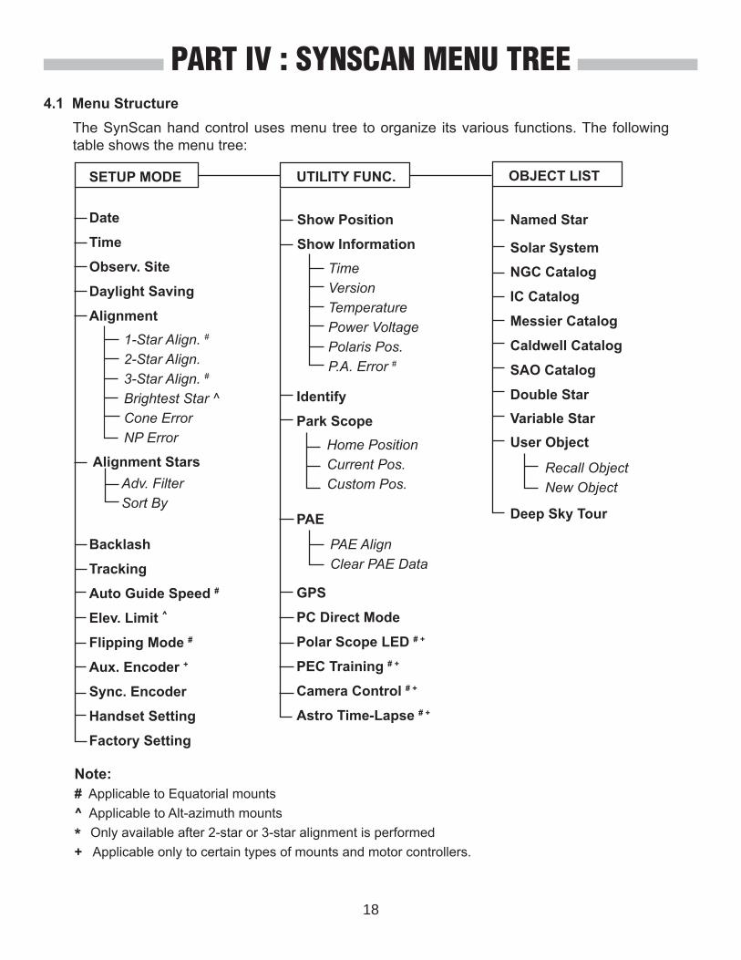
PART IV : SYNSCAN MENU TREE
The SynScan hand control uses menu tree to organize its various functions. The following table shows the menu tree:
4.1 Menu Structure
Note: # Applicable to Equatorial mounts ^ Applicable to Alt-azimuth mounts
* Only available after 2-star or 3-star alignment is performed+ Applicable only to certain types of mounts and motor controllers.

19
PART IV: SYNSCAN MENU TREE
The SynScan hand control’s menu is only accessible after the initialization, or after the star alignment routine is completed (If it is chosen to start.). Users can use the ESC key, the ENTER key, and the two scrolling keys to access the menu.
The functions of these keys are:• ESC key: Used to return to the previous menu or to exit the current operation. Press the ESC
key for several times to go back to the top level of the menu structure.
• ENTER key: Used to enter a sub-menu or to start the operation of the end level menu.
• Scroll keys: Used to scroll within the same level sub-menu.
The SynScan hand control provides short-cut keys for accessing the most commonly used sub-menu. The short-cut keys may only be used while the hand control is in stand-by mode, that is, the SynScan hand control is not executing a specific operation. Users can always press the ESC key to quit the current operation if the short-cut keys are not accessible.
Here is the list of the short-cut keys and their functions:• SETUP: Access to the “Setup” sub-menu.
• TOUR: Access to the “Deep Sky Tour” function.
• UTILITY: Access to the “Utility Function” sub-menu.
• M: Access to the “Messier Catalog” sub-menu.
• NGC: Access to the “NGC Catalog” sub-menu.
• IC: Access to the “IC Catalog” sub-menu.
• PLANET: Access to “Solar System”.
• OBJECT: Access to the “Object List” menu and stay at the “Named Star” sub-menu.
• USER: Access to the “User Object” sub-menu.
• ID: Access to the “Identify” function.
4.2 Accessing Menus
4.3 Short-cut Keys
20
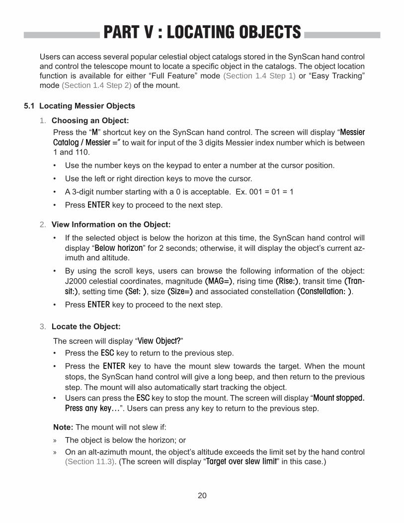
1. Choosing an Object:
2. View Information on the Object:
3. Locate the Object:
Press the “M” shortcut key on the SynScan hand control. The screen will display “Messier Catalog / Messier =” to wait for input of the 3 digits Messier index number which is between 1 and 110.
• Use the number keys on the keypad to enter a number at the cursor position.
• Use the left or right direction keys to move the cursor.
• A 3-digit number starting with a 0 is acceptable. Ex. 001 = 01 = 1
• Press ENTER key to proceed to the next step.
The screen will display “View Object?”• Press the ESC key to return to the previous step.
• Press the ENTER key to have the mount slew towards the target. When the mount stops, the SynScan hand control will give a long beep, and then return to the previous step. The mount will also automatically start tracking the object.
» The object is below the horizon; or » On an alt-azimuth mount, the object’s altitude exceeds the limit set by the hand control
(Section 11.3). (The screen will display “Target over slew limit” in this case.)
• Users can press the ESC key to stop the mount. The screen will display “Mount stopped. Press any key…”. Users can press any key to return to the previous step.
Note: The mount will not slew if:
• If the selected object is below the horizon at this time, the SynScan hand control will display “Below horizon” for 2 seconds; otherwise, it will display the object’s current az-imuth and altitude.
• By using the scroll keys, users can browse the following information of the object: J2000 celestial coordinates, magnitude (MAG=), rising time (Rise:), transit time (Tran-sit:), setting time (Set: ), size (Size=) and associated constellation (Constellation: ).
• Press ENTER key to proceed to the next step.
Users can access several popular celestial object catalogs stored in the SynScan hand control and control the telescope mount to locate a specific object in the catalogs. The object location function is available for either “Full Feature” mode (Section 1.4 Step 1) or “Easy Tracking” mode (Section 1.4 Step 2) of the mount.
5.1 Locating Messier Objects
PART V : LOCATING OBJECTS
21
PART V : LOCATING OBJECTS
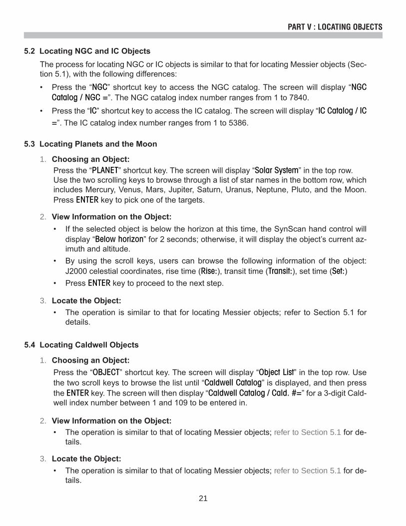
The process for locating NGC or IC objects is similar to that for locating Messier objects (Sec-tion 5.1), with the following differences:
• Press the “NGC” shortcut key to access the NGC catalog. The screen will display “NGC Catalog / NGC =”. The NGC catalog index number ranges from 1 to 7840.
• Press the “IC” shortcut key to access the IC catalog. The screen will display “IC Catalog / IC =”. The IC catalog index number ranges from 1 to 5386.
5.2 Locating NGC and IC Objects
5.3 Locating Planets and the Moon
1. Choosing an Object:
2. View Information on the Object:
3. Locate the Object:
Press the “PLANET” shortcut key. The screen will display “Solar System” in the top row. Use the two scrolling keys to browse through a list of star names in the bottom row, which includes Mercury, Venus, Mars, Jupiter, Saturn, Uranus, Neptune, Pluto, and the Moon. Press ENTER key to pick one of the targets.
• The operation is similar to that for locating Messier objects; refer to Section 5.1 for details.
• If the selected object is below the horizon at this time, the SynScan hand control will display “Below horizon” for 2 seconds; otherwise, it will display the object’s current az-imuth and altitude.
• By using the scroll keys, users can browse the following information of the object: J2000 celestial coordinates, rise time (Rise:), transit time (Transit:), set time (Set:)
• Press ENTER key to proceed to the next step.
5.4 Locating Caldwell Objects
1. Choosing an Object:Press the “OBJECT” shortcut key. The screen will display “Object List” in the top row. Use the two scroll keys to browse the list until “Caldwell Catalog” is displayed, and then press the ENTER key. The screen will then display “Caldwell Catalog / Cald. #=” for a 3-digit Cald-well index number between 1 and 109 to be entered in.
2. View Information on the Object:• The operation is similar to that of locating Messier objects; refer to Section 5.1 for de-
tails.
3. Locate the Object:• The operation is similar to that of locating Messier objects; refer to Section 5.1 for de-
tails.

22
PART V : LOCATING OBJECTS
5.5 Locating SAO Stars
1. Choosing an Object:
2. View Information on the Object:
3. Locate the Object:
Press the “OBJECT” shortcut key. The screen will display “Object List” in the top row. Use the two scroll keys to browse the list until “SAO Catalog” is displayed, and then press the ENTER key. The screen will then display “SAO Catalog / SAO 0000xx” to wait for input of the 4 left-most digits of the 6 digits SAO index number (i.e. “SAO 0238xx”). Press ENTER key and then the hand control will find the first SAO number in the database that matches the 4 left-most digits entered (i.e. “SAO 023801”)
Use the scroll keys to change the last 2 digits until the screen displays the desired SAO index number. Press the ENTER key to confirm the input. (i.e. “SAO 023825”)
Note: The SAO catalog in the SynScan hand control is a sub-set of the SAO catalog. It only contains stars brighter than magnitude 8.
• The operation is similar to that of locating Messier objects; refer to Section 5.1 for de-tails.
• The operation is similar to that of locating Messier objects; refer to Section 5.1 for de-tails.
5.6 Locating Named Stars, Double Stars, and Variable Stars
1. Choosing an Object:
2. View Information on the Object:
Press the “OBJECT” shortcut key. The screen will then display “Object List” on the top row. Use the two scroll keys to browse the list until “Named Star”, “Double Stars” or “Variable Stars” is displayed, and then press the ENTER key to select the desired option. Once inside, use the two scroll keys to go through and find the desired object in the list of star names. Press the ENTER key to confirm the selection.
• The operation is similar to that of locating Messier objects; refer to Section 5.1 for de-tails.
Note: In the operation of step 2, the data of the separation angle (Separation: ) and the position angle (Position Angle) are provided for double stars, and the data of the maximum magnitude (Max.MAG=), minimum magnitude (Min.MAG=), period of variation (Period=) are provided for the variable stars.

23
PART V : LOCATING OBJECTS
5.7 Deep Sky Tour
1. Choosing an Object:
2. View Information on the Object:
The SynScan hand control can generate a list of the most famous deep sky objects which appear in the current sky. Users can pick them one by one and the SynScan hand control can point the telescope to them for observing automatically. This is the “Deep Sky Tour” function.
Press the “TOUR” shortcut key. The screen will display “Deep Sky Tour” in the top row. User can use the two scroll keys to browse through a list of the common names of the deep sky objects and can press ENTER key to pick one of them.
• The screen will display the catalog to which the deep sky object belongs, as well as its catalog index number in the top row. The object’s current azimuth and altitude will be displayed in the bottom row.
• Use the scroll keys to browse the object’s J2000 celestial coordinates, magnitude (MAG=), rise time (Rise: ), transit time (Transit: ), set time (Set: ), size (size=), and asso-ciated constellation (Constellation: ).
• Press ENTER key to proceed to the next step.
3. Locate the Object:• The operation is similar to that of locating Messier objects; refer to Section 5.1 for de-
tails.
3. Locate the Object:• The operation is similar to that of locating Messier objects; refer to Section 5.1 for de-
tails.
Users can define up to 25 objects for observing.
Defining New Objects:
5.8 User Defined Objects
1. Press the “USER” shortcut key. The screen will display “User Object”. Press the scroll keys until “New Object” is displayed on the screen, then press the ENTER key.
2. The screen will display “Coord. Type 1)RA/Dec 2)Axis”. Press “1” to enter R.A./Dec. coordi-nates for a celestial object; press “2” to enter coordinates for a land object.

24
PART V : LOCATING OBJECTS
Recalling Objects:
1. Press the “USER” shortcut key. The screen will display “User Object / Recall Object”. Press the ENTER key.
2. Use the scroll keys to browse through a pre-defined objects list which is indexed from 1 to 25, and then press ENTER. If the selected object has not been defined before, the SynScan hand control will stay at this step for the choosing of another object; otherwise, it will pro-ceed to the next step.
3. The screen will display the coordinates of the selected object. Press the ENTER key again to proceed.
4. The screen will now display “View Object?”
3. Use the left and right direction keys to move the cursor and the numeric keys to edit the coordinates. The scroll keys can be used to change the sign of the declination coordinates or the altitude coordinates. Press the ENTER key after editing.
4. The screen will display “Save?”.
5. The screen will now display “View Object?”.
• Press ENTER to have the mount start slewing towards the selected object. If the object is a celestial object, the mount will start tracking the object automatically after it finishes slewing.
• Press ESC to exit.
• Press the ESC key to proceed to the next step without saving the coordinates.• Press the ENTER key again to start saving the coordinates. Users should use the scroll
keys to select a storage space index number between 1 and 25 and press the ENTER key to save the new coordinates.
• Press ENTER to slew the mount towards the coordinates entered.• Press ESC to exit without moving the mount.
• If the “R.A./Dec.” coordinates is chosen: The screen will display the coordinates to which the telescope is pointing to at the moment.
• If the “Axis” coordinates is chosen: The screen will display the coordinates of the mount’s two axes. The first number is the coordinates of the R.A. axis or azimuth axis, while the second number is the coordinates of the Dec. axis or altitude axis.

25
PART VI : CONFIGURE THE TELESCOPE MOUNT6.1 Choosing Tracking Speed
6.2 Backlash Compensation
6.3 Setting the Altitude Axis Slewing Limits
1. Access the menu “SETUP\Tracking” and press the ENTER key.
2. Use the scroll keys to browse through the following options, and press the ENTER key to pick one.
Users should input the amount of the backlash of both axes of the mount as follows:1. Access the menu “SETUP\Backlash” and press the ENTER key.2. The screen will display “Azm = XoXX’XX” ” or “RA = XoXX’XX” ”. Use the Left/Right keys to
move the cursor and use the numeric keys to fill in a number at the cursor position to input the amount of backlash in the azimuth axis or the R.A. axis. Press the ENTER key to finish the input and proceed to the next step.
3. The screen will display “Alt = XoXX’XX” ” or “Dec = XoXX’XX” ”. Fill in the amount of backlash in the altitude axis or declination axis and then press the ENTER key.
• Sidereal Rate: Enables the mount to track celestial objects at the sidereal rate for ob-serving the stars, deep sky objects, and planets.
• Lunar Rate: Enables the mount to track at the lunar rate for observing the Moon.• Solar Rate: Enables the mount to track at the solar rate for observing the Sun.• Stop Tracking: Stops the mount.• PEC+Sidereal: Enables the mount to track at the sidereal rate and turns on the periodic
error correction (PEC) function. Applies to equatorial mounts only.
Note: Users can turn on the tracking without doing a star alignment process. In this case, the polar alignment should be rather accurate for an equatorial mount; and the mount must be setup to the proper home position before turning on the power (refer to Section 2.1).
Note: Set the backlash value to 0 for an axis to disable backlash compensation for that axis.
If there is backlash in the motor driving system, users might see a lag when moving an object in the FOV of the telescope with the direction keys. The SynScan hand control can control the mount to slew with higher speeds for a specific amount of distance when the user reverses the moving direction of an axis with opposite direction keys. Such backlash compensation function helps the user get faster response from the mount.
Some alt-azimuth mounts have limited slewing range in altitude axis. Users can set the upper and lower altitude limits for such mounts.• When a user asks the SynScan hand control to locate an object whose altitude exceeds
the altitude limits, the SynScan hand control will display “Target is over slew limits!!” and will not start the mount slewing.
• When a user uses the Up or Down direction keys to slew the altitude axis to exceed the al-titude limits, the SynScan hand control will automatically stop the altitude axis and display “Over slew limit. Slewing stop!”. User has to press any key and the SynScan controller will bring the altitude axis back.

26
PART VI : CONFIGURE THE TELESCOPE MOUNT
6.4 Enable/Disable Auxiliary Encoder
6.5 Setting Autoguider Speed
• The screen will display “Set Alt Limits:” in the top row, and “Upper=+XXX. Xo” at the bot-tom row. Use the Left/Right keys to move the cursor and use the numeric keys to fill the upper limits. The leading sign can be changed with the scroll keys. Press the ENTER key to end the input and proceed.
• The screen will display “Lower=+XXX. Xo” at the bottom row, fill in the data in a similar way.
Some Sky-Watcher’s mounts are equipped with auxiliary encoders on their primary axes to support manually rotating the axes without worrying about losing the mount’s alignment sta-tus. Users may turn off the auxiliary encoder to obtain the best pointing accuracy. The auxiliary encoder can be turned on again at any time for manually moving the mount.1. Access the menu “SETUP\Aux. Encoder” and press the ENTER key.2. Use the scroll keys to select between “Enable” or “Disable” and press the ENTER key.Note: After re-enabling the auxiliary encoders, it is recommended to use the direction keys to move both axes for a little bit before asking the hand control to locate an object.
For an equatorial mount with an autoguider port, the SynScan hand control can change the guiding speed of the mount.1. Access the menu “SETUP \ Auto Guide Speed>” and press the ENTER key.2. Use the scroll keys to choose one of the following guiding speeds list: 0.125X, 0.25X,
0.5X, 0.75X, 1X, and then press the ENTER key.
The following are the steps to set the altitude slewing limits:1. Access the menu “SETUP\Elev. Limits”, and press the ENTER key.2. Use the scroll keys to choose options “Enable” or “Disable”, and then press the ENTER key
to confirm.3. If “Disable” is chosen, the SynScan hand control will turn off the altitude limit.4. If “Enable” is chosen, the SynScan hand control will turn on the altitude limit, and users can
input the upper and lower limits as the following:
On an equitorial mount, SynScan hand control automatically decides whether to perform a meridian flipping at the begining of a GOTO, to prevent telescope bumping on the tripod. In some occasion, astrotographers can choose whether to do a meridian flip or not. Access to menu “Setup\Flipping Mode\ “,• Scroll to “Auto Flipping“ and press ENTER key to let the hand control decide automatically.• Scroll to “Force Flipping“ and press ENTER key to force the mount to perform a meridian
flipping for the next GOTO ONLY. • Scroll to “No Flipping“ and press ENTER key to forbit the mount to perform a meridian flip-
ping for the next GOTO ONLY.
6.6 Setting Flipping Mode

27
PART VII : CONFIGURE THE HAND CONTROL7.1 Display, Keypad, and Beeper
7.2 Alignment Star Filter
7.3 Sorting Method of the Alignment Star List
1. Access the menu “Setup \ Handset Setting” and press the ENTER key.2. Use the scroll keys to select “LCD Contrast”; then use the left/right direction keys to adjust
the contrast of the LCD screen.3. Use the scroll keys to select “Beep Volume”; then use the left/right direction keys to adjust
the volume of the beeper.4. Use the scroll keys to select “LED Backlight”; then use the left/right direction keys to adjust
the brightness of the keypad’s LED backlight.5. Use the scroll keys to select “LCD Backlight”; then use the left/right direction keys to adjust
the brightness of the LCD screen’s backlight.6. Press ESC to exit the adjustment.
1. Access the menu “Setup \ Alignment Stars \ Sort by” and press the ENTER key.2. Use the scroll keys to select “Magnitude” and press the ENTER key to sort the list by mag-
nitude (from the brightest to the faintest).3. Use the scroll keys to select “Alphabet” and the press the ENTER key to sort the list alpha-
betically.
• The alignment star’s altitude must be above 15 degrees.• For an equatorial mount, the alignment star’s declination must be between -75 and +75
degrees.• For an alt-azimuth mount, the alignment star’s altitude must be below 75 degrees or within
the altitude limits defined by the user (Section 6.3).
Not all combinations of alignment stars are good for a 2-star alignment or 3-star alignment. The SynScan hand control uses a built-in advanced alignment star filter to show only the stars which is suitable to work with the 1st or 2nd alignment star(s), when asking the user to choose the 2nd or 3rd alignment star. It helps to improve the success rate of the alignment.
Some advanced users or those who have limited visible sky can turn on/off this advance filter with the following steps:1. Access the menu “Setup \ Alignment Stars \ Adv. Filter” and press the ENTER key.2. Use the scroll keys to choose “OFF” and then press the ENTER key to disable the filter.3. Use the scroll keys to choose “ON” and then press the ENTER key to enable the filter.
Note: Even if the advanced filter function is turned off, the SynScan hand control will still apply the following rules to generate the list of alignment stars:

28
PART VIII : AUXILIARY FUNCTIONS8.1 Editing Date, Time, Coordinates, Time Zones, and Daylight Saving Time
8.2 Re-aligning the Mount
8.3 Show Position
8.4 Show Time and Local Sidereal Time
8.5 Display Version Information
1. Press the “SETUP” shortcut key.2. Use the scroll keys to select “Date” and press the ENTER key to edit the date. Press the
ENTER key to apply change, or press the ESC key to exit. (Note: The setting of the date is in mm/dd/yyyy format, i.e. 10/24/2012)
3. Use the scroll keys to select “Time” and press the ENTER key to edit the time. Press the ENTER key to apply change, or press the ESC key to exit. (Note: The setting of the time is in 24 hours format, i.e. 18:30:00 is entered for 6:30pm.)
4. Use the scroll keys to select “Observ. Site” and press the ENTER key to edit the geographic coordinates, time zone and elevation. Press the ENTER key to apply change or press the ESC key to exit.
5. Use the scroll keys to select “Daylight Saving” and press the ENTER key, and then use the scroll keys to select between “Yes” and “No”. Press ENTER to apply change.
Note: refer to Step 5 in Section 2.2 for detailed input instructions.
1. Access the menu “UTILITY FUNC \ Show Position” and press the ENTER key.2. Use the scroll keys to switch between the following coordinates:
• Dec/RA: Displays the current celestial coordinates of the telescope.• Alt/Azm: Displays the current horizontal coordinates of the telescope.• Ax1/Ax2: Displays the current coordinates of the mount. Ax1 is the position of the dec-
lination or altitude axis, and Ax2 is the position of the R.A. or azimuth axis.Tip: Users can use the direction keys to slew the mount to specific coordinates by referring to the real-time coordinates display.
Users can execute the 1-star alignment, 2-star alignment or 3-star alignment at any time with-out restarting the mount.1. Access the menu “SETUP \ Alignment” and then press the ENTER key.2. Use the scroll keys to select an alignment method and press the ENTER key to start the
alignment process. For detailed instructions on alignment, please refer to PART III.
Access the menu “Utility Func \ Show Information \ Time” and press the ENTER key to display the current local time and the local sidereal time. Press the ESC key to exit.
Access the menu “Utility Func \ Show Information \ Version” and press the ENTER key, and then use the scroll keys to browse through the following information. Press the ESC key to exit.

29
PART VIII : AUXILIARY FUNCTIONS
8.10 Changing Polar Scope Illumination Level
8.11 Identifying Objects
• H.C. Firmware: The firmware version of the SynScan hand control.• Database: The database version of the SynScan hand control • H.C. Hardware: The hardware version of the SynScan hand control.• Motor Controller: The firmware version of the motor controller of the mount.• H.C. Serial #: The serial number of the SynScan hand control.
This function applies only to certain Sky-Watcher’s equatorial mounts that are equipped with a polar scope illuminator. 1. Access the menu “Utility Func \ Polar Scope LED” and press the ENTER key.2. Use the Left/Right direction keys to adjust the illumination level. Press the ENTER key to
confirm and exit.
After aligning the mount, the SynScan hand control can be used to identify the object to which the telescope is pointing.
1. Center the object to be identified in the telescope’s eyepiece.
8.6 Display Temperature
8.8 Display Polaris Position
8.7 Display Power Voltage
8.9 Display Polar Alignment Error
Access the menu “Utility Func \ Show Information \ Temperature” and press the ENTER key to display the current temperature. Press the ESC key to exit.
Access the menu “Utility Func \ Show Information \ Polaris Pos.” and press the ENTER key, and then use the scroll keys to switch the screen display between “Polaris Position in P.Scope = HH:MM”. and “Hour Angle of Polaris = HH:MM“. Press the ESC key to exit.
Access the menu “Utility Func \ Show Information \ Power Voltage” and press the ENTER key to display the power voltage applied to the mount. Press the ESC key to exit.
Access the menu “Utility Func \ Show Information \ P.A Error” and press the ENTER key. The screen will display “Mel=+DDDoMM’SS Maz=+DDDoMM’SS”. The “Mel” value is the polar align-ment offset in elevation, and the “Maz” value is the polar alignment offset in azimuth. These data is valid only after a 2-star alignment or a 3-star alignment.
30
PART VIII : AUXILIARY FUNCTIONS
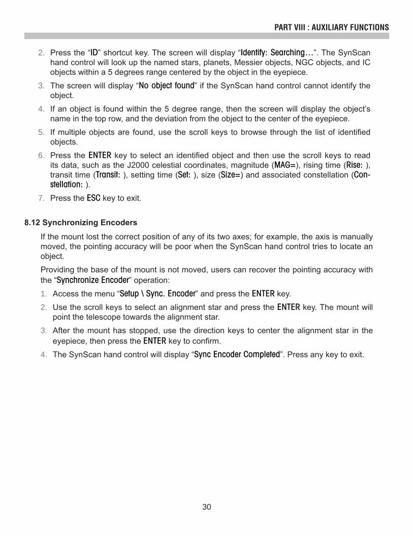
8.12 Synchronizing Encoders
If the mount lost the correct position of any of its two axes; for example, the axis is manually moved, the pointing accuracy will be poor when the SynScan hand control tries to locate an object.
Providing the base of the mount is not moved, users can recover the pointing accuracy with the “Synchronize Encoder” operation:
1. Access the menu “Setup \ Sync. Encoder” and press the ENTER key.
2. Use the scroll keys to select an alignment star and press the ENTER key. The mount will point the telescope towards the alignment star.
3. After the mount has stopped, use the direction keys to center the alignment star in the eyepiece, then press the ENTER key to confirm.
4. The SynScan hand control will display “Sync Encoder Completed”. Press any key to exit.
2. Press the “ID” shortcut key. The screen will display “Identify: Searching…”. The SynScan hand control will look up the named stars, planets, Messier objects, NGC objects, and IC objects within a 5 degrees range centered by the object in the eyepiece.
3. The screen will display “No object found” if the SynScan hand control cannot identify the object.
4. If an object is found within the 5 degree range, then the screen will display the object’s name in the top row, and the deviation from the object to the center of the eyepiece.
5. If multiple objects are found, use the scroll keys to browse through the list of identified objects.
6. Press the ENTER key to select an identified object and then use the scroll keys to read its data, such as the J2000 celestial coordinates, magnitude (MAG=), rising time (Rise: ), transit time (Transit: ), setting time (Set: ), size (Size=) and associated constellation (Con-stellation: ).
7. Press the ESC key to exit.

31
PART IX : CONNECTING TO A COMPUTER9.1 Working with Astronomical Applications
9.2 PC Direct Mode
After the SynScan hand control is initialized, it can communicate with a computer via the RS-232C connection on its multi-purpose port. The computer must have a RS-232C serial port; otherwise, a USB-to-Serial adapter is required. Connect the SynScan hand control and the serial port with the PC-Link cable (the RJ-12 to D-Sub 9 cable) which comes with the tele-scope mount.
The most popular astronomical applications which can work with the SynScan hand control are:
• Planetarium Applications: Users can click on an object on the sky map to command the telescope to point to the object.
• Autoguider Applications: Corrects minor tracking error dynamically for long exposure as-trophotography.
Note: The SynScan hand control cannot work with the above application when it is in the fol-lowing status:• When checking GPS information (Section 12.2).• During the PEC training process.• When working in PC Direct mode (Section 9.2).
PC Direct Mode is a special mode for the SynScan hand control to work with a PC. Under this mode, the SynScan hand control still uses the same hardware connection as described in Section 9.1, but the SynScan hand control becomes a repeater between the PC and the motor controller in the telescope mount. The application running on the PC controls the motor controller directly. Currently, the PC direct mode is mainly used to update the motor controller’s firmware.
• Access the menu “Utility Func. \ PC Direct Mode” and press the ENTER key. The screen will display “PC Direct Mode\Press ESC to exit”.
• Press and hold the ESC key more than 1 second to exit PC Direct Mode.• Users can still use the direction keys to move the telescope mount.

32
PART X : UPDATING FIRMWARE10.1 Hardware Requirements
10.2 Preparation
10.3 Updating Firmware
1. A SynScan hand control with firmware version 3.0 or above.2. A computer running Windows 95 or a later version.3. A RS-232C serial port on the computer, or a USB-to-Serial adaptor.4. The PC-Link cable (D-Sub9 to RJ-12) which comes with the mount.5. A DC 7.5V to 12V DC power supply which can output at least 100 mA current.
1. Create a new folder in the computer (for example, C:\SynScan) to save relevant files.
2. Download the application package “SynScan Firmware Loader” from http://www.skywatch-er.com/ and extract the file “SynScanFirmwareLoader.exe” to the above folder.
3. Download the latest firmware package and extract the “.SSF” file to the above folder.
1. Connect the computer and the SynScan hand control with the PC-Link cable.
2. Press and hold the “0” and “8” keys simultaneously, and then power on the hand control. The hand control will give a beep, and display “SynScan Update” on the screen. Release the “0” and “8” keys.
3. On the computer, run the SynScanFirmwareLoader.exe. An application window is show in Fig 10.3a.
• Use the “Browse” button to load the latest firmware file (“.SSF” file)• Check the “Enforce database update” to enforce updating the hand control’s database.
Clear it to let the application determine whether it is necessary to update the database.
Fig. 10.3a

33
10.4 Troubleshooting
1. If a window pops up and displays the message: “Cannot connect to a SynScan hand control” after clicking the “Update” button or the “H.C. Version” button, close the message window and click the “Update” button or the “H.C. Version” button to try again. If the application dis-plays the message again, check the cable connections and ensure the USB-to-Serial Port adaptor is working.
2. If the firmware update fails, the SynScan Firmware Loader will pop up a window with mes-sage “Firmware update failed. Cycle power to SynScan and try again!”. Close the window and power off the hand control. Then repeat the firmware update process again.
3. If the update process failed in the middle of updating, try to press the SETUP button on the SynScan hand control to use other communication speeds: “Mi” or “Lo.”
4. After the loading starts, the application will display a percentage number at the bottom of the windows to show the progress.
5. Once update is complete, the application will display a green bar with “Update Complete” at the bottom of the window.
PART X : UPDATING FIRMWARE
• Check the “Auto-detect COM port” to let the application detect the proper serial port that will connect to the SynScan hand control. Clear it to manually choose the COM Port and select a serial port from the “COM port” drop-down list.
• Click the “HC Version” button to check the versions of the hardware, firmware, and database.
• Click the “Update” button to start loading the firmware to the SynScan hand control.
• Mi - Medium speed• Lo - Low speed
34
If the mount of the telescope have not been moved after an observing session, the user can park the telescope to keep the alignment data, PAE data and PEC data, and start observing in the next session without redoing the alignment and calibration.
Parking1. Access the menu “UTILITY FUNC\Park Scope” and press the ENTER key.2. The screen will display “Park to…”. Use the scroll keys to choose one from the following
parking position and press the ENTER key.
• Home Position: Park the telescope to the Home Position (Refer to section 2.2.1).• Current Pos.: Park the telescope at the current position.• Customer Pos.: Park at the previous parking position which is used in the previous o
serving session.
» Press “1” key to resume the mount from the parking status. After the regular initializa-tion steps, the SynScan hand control will be ready for full feature operation like the previous observing session.
» Press “2” key to abandon the previous saved parked position and alignment data and start a regular observing session.
11.1 Parking Telescope
PART XI : ADVANCED FUNCTIONS
3. The mount will slew to the parking position (except parking at the current position), and the SynScan hand control will give a long beep when the mount stops. The screen will display “Position saved. Turn off power”.
4. Users may now turn off power to the mount, or press the ESC key to cancel parking.
Resuming• Turn on power to the mount.
• Pass through the initial steps.
• When the screen will display “Start from park pos.? 1) Yes 2)No”,
11.2 Pointing Accuracy Enhancement
The pointing accuracy enhancement (PAE) function enables the telescope mount to obtain enhanced pointing accuracy in specific small areas.
After a 1-star, 2-Star or 3-star alignment, the telescope mount might still have a small pointing error due to many factors, such as the flexure of the telescope, atmospheric refraction or oth-er mechanical issues. The amount of pointing error might vary in different portions of the sky.

35
PART XI : ADVANCED FUNCTIONS
The SynScan hand control divides the sky into 85 small zones, and users can calibrate the pointing error for each of these zones. The next time that the SynScan controller tries to locate an object in the calibrated zone (or a zone nearby), it will automatically apply the re-corded calibration data to compensate the pointing error.
This function is useful for locating faint deep sky objects, and it is also helpful to obtain con-sistent pointing accuracy for a permanent observatory.
Here are the instructions on using the PAE function:1. Perform a 1-star alignment, 2-star alignment, or a 3-star alignment.
2. Choose a celestial object in a zone of interest as reference by referring to a sky map or planetarium software. In general, it is a rather bright star, but users can also use other objects. Use the SynScan hand control to control the mount to point the telescope to the reference object.
3. Use one of the following operations to start the PAE calibration:• Press the “UTILITY” shortcut key, access to sub-menu “PAE\PAE Align”, and then press
the ENTER key.• Press and hold the ESC key for two seconds.
4. The screen will display “Center Object:” in the first row, and display the name of the refer-ence object in the bottom row. (If the last object is launched from a PC, then instead of the name of the reference object, it will display “The last target”.) Now use the direction keys of the hand control to center the object in the telescope’s FOV, and then press ENTER to confirm. Remember to end the centering operation by pressing the Right and Up direction keys together.
5. Repeat Step 2 to 5 for viewing different portions of the sky.
Note:• Whenever the SynScan hand control locates an object, it will automatically check whether
a PAE calibration data is available, and apply the compensation accordingly. No manual intervention is required.
• If multiply PAE calibration is performed in the same zone, the previous calibration data will be overwritten.
• Users can access the menu “UTILITY > PAE > Clear PAE data” to clear all PAE calibration data.
• The PAE calibration data will be automatically cleared after a 1-star alignment, 2-star alignment or 3-star alignment.
36
PART XI : ADVANCED FUNCTIONS
The polar alignment function can help users to polar align an equatorial mount accurately.
Here are the operating instructions:
11.3 Polar Alignment without Polar Scope
1. Complete a 2-star alignment or a 3-star alignment. At the end of the alignment, the Syn-Scan hand control will display the polar alignment error (refer to Section 3.3). Users can use the data to determine whether it is necessary to adjust the polar alignment.
2. Press the “SETUP” shortcut key, and then access to sub-menu “Alignment\Polar Align. >”, press the ENTER key to proceed to the next step.
3. The screen will display “Select a Star”.
4. Use the direction keys to center the reference star in the eyepiece of the telescope after the mount stops slewing. Remember to end the centering operation with Up and Right direction keys. Press the ENTER key to proceed to the next step.
5. The screen will now display the polar alignment error in altitude (Mel=dd’mm’ss”). Users can then use the data to determine whether or not to adjust the altitude of the R.A. axis in the next step. Press the ENTER key to proceed.
6. The mount will slew to a new position. When it stops, the screen will display “Adjust Altitude:”. By using ONLY the altitude control of the mount (do not touch the azimuth control), bring the reference star back to the closest point to the center of the FOV of the telescope’s eyepiece. Remember the reference star’s current position in the eyepiece for later adjustment. Press the ENTER key to confirm the centering operation.
7. The screen will now display the polar alignment error. Users can then use the data to determine whether or not to adjust the azimuth of the mount in the next step. Press the ENTER key again to proceed to the next step.
8. The mount will slew to a new position. When it stops, the screen will display “Adjust Azi-muth:” By using ONLY the azimuth control of the mount (do not touch the altitude control), bring the reference star back to the closest point to the previous position (at the end of Step 6). Press the ENTER key to confirm the centering operation.
9. The screen will display the polar alignment error again, press the ENTER button to end the polar alignment process.
10. Go back to the “Alignment” menu on the SynScan hand control and execute another 2-Star or 3-Star alignment, and then check the polar alignment error data reported at the end of the 2-star alignment or 3-star alignment. Repeat Step 2 to Step 9 until the error is small enough and acceptable. Generally, users can get up to 1 arc-minute polar align-ment accuracy after repeating this polar alignment process 2 or 3 times.
Note:• Users can press the ESC key at any time during the polar alignment process to exit.
• Use the scroll keys to browse through a list of star names and press the ENTER key to pick one as the reference star for polar alignment.
• The mount will start slewing to point the telescope to the reference star.

37
PART XI : ADVANCED FUNCTIONS
1. Using the SNAP port on the telescope mount: Several Sky-Watcher’s equatorial mounts (such as the AZ-EQ6 GT and the EQ8) are equipped with a SNAP port. Users can use a proper shutter release control cable to con-nect this port to the same port on the camera.
2. Using the multi-purpose port on the SynScan hand control: The SynScan hand control uses 2 pins (The SHUTTER and COMMON pins in the dia-gram of Appendix 3) of its multi-purpose port to control the shutter release of a DSLR camera. Users may use a proper shutter release cable to connect the SynScan hand control and a camera.
1. Press the “UTILITY” shortcut key, access to sub-menu “Camera Control \ Configuration” and press the ENTER key.
2. Edit the interval between each exposure (in MM:SS format) and press the ENTER key .
3. Use the scroll keys to browse through a list of 8 groups of parameters. A sample screen-shot is shown below:
The leading number (“1”) is the index number of this group; the “mm:ss” data is the ex-posure time in minutes and seconds; and the ending 3 digits number is the frames to be shot. Press the ENTER key to pick a group and proceed to the next step.
The SynScan hand control can control a DSLR camera to do astrophotography. It can accept 8 groups of “Exposures Time - Frames” parameters, and then controls the camera to take batch exposures without manual intervention.
To use the camera control function, the camera must be equipped with a shutter release con-trol port and can be set to the bulb exposure mode.
11.4 Camera Control
Connecting the Camera
Setup Control Parameters
Select a Group 1. mm:ss X 000
• The initial polar alignment should not be too far off to avoid the polar alignment error in azimuth exceeding the adjustment range of the mount.
• It is necessary to use a reticle eyepiece in the 2-Star alignment, 3-star alignment and polar alignment process.
• Generally, the cone error in a telescope-mount setup might reduce the accuracy of this polar alignment process. Therefore, it is recommended to reduce or eliminate the cone error before the polar alignment process (Refer to APPENDIX 1 : ELIMINATING CONE ERROR ON EQUATORIAL MOUNTS).
• It is recommended that the user verifies the accuracy of the 2-star alignment or 3-star alignment before starting the polar alignment process by locating several objects in dif-ferent areas of the sky. If the pointing accuracy is low, try to use another set of alignment stars for the 2-star or 3-star alignment process.

38
PART XI : ADVANCED FUNCTIONS
• Use the left and right keys to move the cursor and use the numeric keys to fill the dig-its with the cursor. Press the ENTER key to end setting the exposure time.
• Now the screen is changed to set the frames to be shot for this group, as shown be-low. Use the left and right keys to move the cursor and use the numeric keys to fill in the digits with the cursor. Press the ENTER key to end setting the frames.
5. After setting all groups of the parameters, press the ESC key to exit the configuration pro-cess.
4. The first row of the screenshot below indicates the index number of the group being edited. The second row shows the exposure time of this group.
Edit Group#1 Exposure mm:ss
Edit Group#1 Repeats 000
1. Set the camera to bulb exposure mode.
2. Press the “UTILITY” shortcut key, access to the sub-menu “Camera Control \ Shoot”, and press the Enter key.
3. The SynScan hand control will start to take batch exposure and display the progress data on the screen, a sample screenshot is shown below:
• The top row shows the group index and the frames pending. • The bottom row shows the remaining exposure time of the current frame.• At the end of each frame, the SynScan hand control will give a beep and wait for 2
seconds before the next exposure.
Batch Exposure
4. During the batch exposure, users can press the ESC key to suspend the operation. The screen will display “Shoot Suspended. 1) Resume 3) Exit”. Press “1” key to resume batch exposure or press “3” key to exit.
Shoot Suspended 1) Resume 3) Exit
Shooting#1: 003 Release mm:ss
• The SynScan hand control will return to the status of Step 2 for users to choose and edit another group of parameters.
Note: To disable a group, set either the “Exposure” or the “Repeats” parameters to 0.

39
PART XI : ADVANCED FUNCTIONS
Notes:• It is recommended to use a high-power telescope and a reticle eyepiece for the PEC train-
ing. A digital eyepiece with a computer is preferred.• For the equatorial mounts that support PPEC (such as the AZ-EQ6 GT and EQ8 mounts),
an autoguider can be used to replace manual guiding in PEC training process. In such cases, it is recommended to turn on the autoguiding for at least one minute before starting the PEC training process. The total time for the PEC training of these mount can be as long as two cycles of the period error.
Once PEC training is completed, access the menu “Setup\Tracking\PEC+Sidereal” and press the ENTER key to start the PEC replay, that is, start to compensate the period error. Choosing other items in the menu “Setup\Tracking” will turn off the PEC.
PEC Replay
11.5 Periodic Error Correction (PEC) for EQ Mount
1. Polar align the equatorial mount accurately, and then perform a star alignment.
2. Choose a star close to the celestial equator, point the telescope towards it and start the mount tracking. Center the star in the telescope’s eyepiece.
3. Access the menu “UTILITY FUNC\PEC Training” and press the ENTER key, the screen will display “Select Speed: 1)0.125X 2)0.25X”. This is the speed used to adjust the position of the star in the FOV of the telescope when a user presses the Left or Right direction key on the SynScan hand control. Choosing a 0.125X sidereal rate is recommended for a smaller FOV of telescope, and a 0.25X sidereal rate is recommended for a wider FOV of telescope. Press the “1” or “2” key to make a selection and proceed to the next step.
4. The screen will display the elapsed time. Use the Left and Right direction keys to con-trol the mount and keep the star at the same spot in the FOV of the telescope until the SynScan hand control gives a long beep and stops displaying the time. The total time for this training process depends on mount models.
The periodic error correction function applies to an equatorial mount only.
All equatorial mount has periodic tracking error which is not critical for visual observing but might lower the picture quality of long exposure astrophotography. The SynScan hand con-trol has the periodic error correction (PEC) function to improve the tracking performance for astrophotography.
Depending on the model of the equatorial mount, there are two types of PEC. One is soft-ware based PEC (SPEC), which applies to Sky-Watcher’s EQ3/EQ5/HEQ5/EQ6 Pro mount. The other is permanent PEC (PPEC), which applies to Sky-Watcher’s AZ-EQ6 GT mount and EQ8 mount. The SynScan hand control can detect the mount model and choose the corre-sponding PEC algorithm.
The PEC function is a training-replay process.
PEC Training:

40
PART XI : ADVANCED FUNCTIONS
11.6 Calibrating Auto-Home Offset
• Press “1” key to keep the original Home Position Offset. • Press “2” to use the results obtained from the 1-star alignment to calibrate the home
position offset.
1. PEC can only compensate tracking errors on the R.A. axis. Therefore, a precise polar alignment is still required to track minor errors on the Dec. axis.
2. After turning on the PEC replay, it is recommended to wait for at least one cycle time of the period error before taking a picture.
3. To re-use the PEC data on a mount which supports SPEC, users should park the tele-scope before shutting off power (refer to Section 11.1). This limitation does not apply to the mounts which support PPEC.
Some Sky-Watcher’s equatorial mounts (ex. the EQ 8 mount) has the Auto-Home function which can set the mount to a standard home position after turning on the power. The offset of the home position can be calibrated and compensated with the following procedures:1. Polar-align the equatorial mount accurately.2. Turn off the power, and then turn it on again, and then initialize the hand control.3. When SynScan hand control asks “Auto-Home?”, press the “1” key to execute the au-
to-home process.4. Finish the subsequent initialization steps.5. At the end of the initialization, choose 1-star alignment to align the mount.6. At the end of the 1-star alignment, the hand control will ask “Update H.P.O? 1)No 2) Yes”
(The “H.P.O.” means Home Position Offset).
11.7 Setting Cone Error and Non-Perpendicular Error• Cone error (CE) occurs when a telescope’s optical axis is not perpendicular to the equato-
rial mount’s declination axis (or the altitude-azimuth mount’s altitude axis). • Non-perpendicular error (NPE) occurs when the mount’s two axes are not orthogonal. Without proper compensation, both of the above errors could lead to inaccurate pointing when the telescope system tries to locate a celestial object automatically. The value of these errors can be set on the hand control for compensation.1. Access menu “Setup\Alignment\Cone Error“ to display and modify the cone error.
• The cone error compensation will be applied to 1-Star, 2-Star and Brightest-Star align-ments.
• In a 3-Star alignment, SynScan hand control measures the current cone error and over-writes the old cone error value.
• Cone error is quite common in most telescope systems, but and alt-az mount is less sensitive to cone error. Generally, user can set cone error to 0 on a alt-az mount.
2. Access menu “Setup\Alignment\NP Error“ to display and modify non-perpendicular error.
41
PART XI : ADVANCED FUNCTIONS
11.8 Astronomical Time-Lapse PhotographyThe SynScan hand control can coordinate a Skywatcher telescope mount(equitorial or alt-az mount) and a DSLR camera to take series of long exposure photo of the night sky. These series photos can be used to make a time-lapse video. The SynScan hand control accom-plishes this task through the following sequence.1. At an initial position, turn on sidereal tracking of the mount and release the shutter of the
camera at the same time.2. Keep mount tracking and camera shutter opened until the preset exposure time reaches.3. Close the camera shutter and return the mount to the initial position.4. Repeat step 1 to 3 until preset numbers of photos is taken.
Both the “SNAP“ port on a Sky-watcher mount or the multi-purpose port of the SynScan hand control can be used to control the camera with proper cables availiable from Sky-watcher product dealers.
Operation Details:1. Connect the camera’s shutter control port to the mount(or SynScan hand control) with
proper cables. 2. Point the camera to the desired orientation.3. Access the menu “UTILITY\Astro Time-Lapse \ Configuration\Exposure Time” to set the exposure
time of the camera.4. Access the menu “UTILITY\Astro Time-Lapse \ Configuration\Repeat Times” to set the number of
photos which will be taken.5. Access the menu “UTILITY\Astro Time-Lapse \ Configuration\Shoot” to start taking photos.6. The LCD will display remaining photos and remaining time of the ongoing exposure.7. Press ESC key to pause or cancel the shooting.
• Generally, NPE is very small and can be ignored(Set to 0) in most cases unless superior pointing accuracy is required.
Note: If the value of CE or NPE entered in the hand control is not 0, the hand control will give a reminding message “CAUTION: Prev. NPE, CE applied.“ at the end of the alignment routine. User should make sure that the stored CE and NPE parameters are correct for the current system setup; otherwise, these value should be set to 0.

42
PART XII : USING A SYNSCAN GPS MODULE
12.1 Initialization of the Hand control with a SynScan GPS Module
12.2 Checking GPS Information
3. The hand control will then ask the user whether to use the Daylight Saving Time. Use the scroll keys to select between “YES” and “NO” and press the ENTER key to confirm and pro-ceed.
4. The screen will now display “GPS fixing…”. It means that the GPS module is trying to fix to the GPS satellites.
5. After the SynScan GPS module fixes to the satellites, the SynScan hand control will con-tinue the initialization process.
1. Plug the SynScan GPS module into the multi-purpose port (the 6 pins RJ-12 port) located at the bottom center of the SynScan hand control. Place the GPS module on a horizontal surface.
2. Access the menu “Utility Func. \ GPS” in the menu and press the ENTER key.3. The screen will now display “GPS fixing…”. It means that the GPS module is trying to fix to
the GPS satellites.4. After the SynScan GPS module fixes to the satellites, the screen will display “GPS Infor-
mation:”. Use scroll keys to browse through the following information. Press the ESC key to exit.
• Use the left and right direction keys to move the cursor on the screen.• Use the scroll keys to change or switch the sign for the time zone. Use “+” for the time
zones in the Eastern Hemisphere, use “-” for the time zones in the Western Hemi-sphere.
• Use the numeric keys to fill the time zone value in ±hh:mm format.• Press ENTER to confirm and proceed.
• M.O.V: Local magnetic declination• Lat: Local latitude• Lo: Local longitude• Date: Local date• UT: Greenwich Mean Time• LT: Local time
• TimeZone: Local time zone• LST: Local sidereal time• Elevation: Local elevation• Quality: Quality of GPS fixing• Number of SV: Number of GPS satellites in view• # of SV(fix): Number of GPS satellites fixed
The initialization process of the SynScan hand control with a SynScan GPS plug-in differs from a regular one.1. Plug the SynScan GPS module into the multi-purpose port (the 6 pins RJ-12 port) located
at the bottom center of the SynScan hand control. Place the GPS module on a horizontal surface and turn on the power of the mount.
2. If the SynScan hand control detects the connection of a GPS module, it will ask for the local time zone:
Users may purchase a SynScan GPS module to acquire accurate local geographical coordi-nates and local time; it will help improve the accuracy of the mount alignment and the polar alignment.

43
Testing for Cone Error
Eliminating Cone Error
APPENDIX I : ELIMINATING CONE ERROR
• If the pointing accuracy is still good, then the mount system has small or no cone error.• If the pointing accuracy becomes poor, and most of the error is on the R.A. axis (that is,
the object can be brought back to the center of the eyepiece using the left or right di-rection keys), it means that the cone error of the telescope-mount system is quite large.
If the telescope’s optical axis is not perpendicular to the declination axis of the equatorial mount, then there is cone error in the telescope-mount system. The cone error might lower the accuracy of locating an object or the accuracy of the Polar-Alignment process.
1. Perform a precise polar alignment on the equatorial mount, and then perform a two-star alignment. The alignment stars should be located on the same side of the meridian and their declination deviation should be within 10 to 30 degrees.
2. Use the SynScan hand control to locate a few objects on the same side of the meridian as the alignment stars. The pointing accuracy should be quite good.
3. Use the SynScan hand control to locate a few objects on the other side of the meridian as the alignment stars.
1. Rotate the R.A. axis to level the counterweight shaft.2. Center the Polaris in the polar scope.3. Point the telescope to the Polaris, rotate the Dec. axis to bring the Polaris as close as pos-
sible to the center of the finder scope or the telescope’s eyepiece.4. Fine tune the azimuth and latitude of the mount to center the Polaris in the telescope’s
eyepiece.5. Rotate the R.A. axis 180 degrees. (the counterweight shaft should be leveled and pointed
to the other side of the mount). If the Polaris can be put to the center of the eyepiece by rotating the Dec. axis only, it means the cone error is small and no further adjustment is needed; otherwise, continue to the following steps.
6. Rotate the Dec. axis to bring the Polaris as close as possible to the center of the finder scope or the telescope’s eyepiece.
7. Slightly push the eyepiece end of the telescope in a HORIZONTAL direction while looking into the eyepiece, find the direction which will bring the Polaris closer to the center of the eyepiece. In this way, a user can determine the direction in which you should re-position the telescope on the saddle or the mounting bar to reduce the cone error.
8. Use a shim (or other method) on the proper side of the saddle or the mounting bar to raise the telescope. Look into the eyepiece while applying the shim. Reduce the deviation be-tween the Polaris and center of the eyepiece to HALF.
9. Repeat Steps 4 and 5 to check whether the cone error is acceptable, repeat Steps 6, 7 and 8 if necessary.
Tips: • It is recommended to use a reticle eyepiece and align the track of the Dec. movement with
one of the lines of the reticle.• This adjustment can be done in day time by using a distance point object to replace the
Polaris.

44
APPENDIX II : SYNSCAN SELF-DIAGNOSISThe SynScan hand control contains a built-in self-diagnosis program. To run a full test, users should prepare two “Loop-Test Plug” by referring to Appendix 3 and the following instructions:
• Short the pin-5 (RX_TTL) and pin-6 (TX_TTL) of a RJ-45 plug.
• Short the pin-2 (TX_RS232C) and pin-5 (RX_RS232C) of a RJ-12 plug.
Here are the diagnosis steps:
1. Insert the two “Loop-Test Plug” to the corresponding port of the SynScan hand control.
2. Press “2” and “5” simultaneously and power on the hand control.
3. The hand control will give a short beep and display “SynScan B.I.T.” for a short time.
4. The LCD screen will become fully black and then fully clear for a while for the purpose of checking the LCD display.
5. If there is any problem for the RS-232C function on multi-purpose port (the RJ-12 outlet) or no Loop-Test Plug connected to the multi-purpose port, the screen will display “COM1 ERROR”. Press ENTER to continue.
6. If there is any problem on the mount port or no Loop-Test Plug connected to the mount port (the RJ-45 outlet), the screen will display “COM2 ERROR”. Press ENTER to continue.
7. If everything is fine, the testing will go to Step 8; Otherwise, the SynScan hand control will show “EEPROM ERROR” or “Flash ERROR”. Press ENTER to continue in such case.
8. Check keypad and other features:
• The screen will display “Key=” in the top row. If a key is pressed, the name of the key will be displayed, and the hand control also beeps while the key is pressed.
• Power voltage and the temperature will be displayed on the bottom row of the screen.
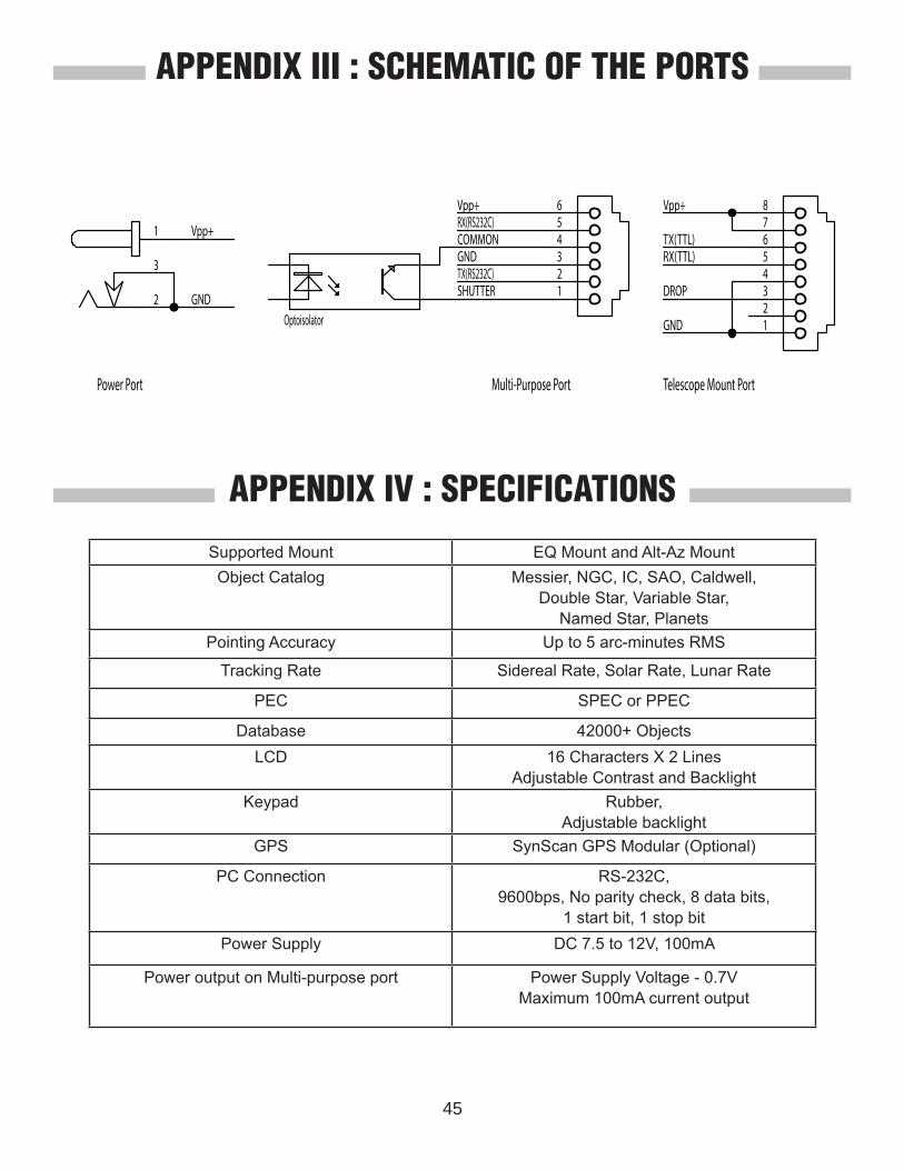
45
Supported Mount EQ Mount and Alt-Az MountObject Catalog Messier, NGC, IC, SAO, Caldwell,
Double Star, Variable Star, Named Star, Planets
Pointing Accuracy Up to 5 arc-minutes RMS
Tracking Rate Sidereal Rate, Solar Rate, Lunar Rate
PEC SPEC or PPEC
Database 42000+ ObjectsLCD 16 Characters X 2 Lines
Adjustable Contrast and BacklightKeypad Rubber,
Adjustable backlightGPS SynScan GPS Modular (Optional)
PC Connection RS-232C,9600bps, No parity check, 8 data bits,
1 start bit, 1 stop bitPower Supply DC 7.5 to 12V, 100mA
Power output on Multi-purpose port Power Supply Voltage - 0.7V Maximum 100mA current output
APPENDIX III : SCHEMATIC OF THE PORTS
APPENDIX IV : SPECIFICATIONS
234
1
5678
Telescope Mount Port
GND
Vpp+
TX(TTL)RX(TTL)
234
1
56
Multi-Purpose Port
GND
Vpp+
Optoisolator
DROP
RX(RS232C)
TX(RS232C)
1
3
2
Power Port
Vpp+
GND
COMMON
SHUTTER
SynScanTM