Instruction Manual, May 2007 - David's Reloading...
15
Instruction Manual, May 2007 Case Preparation Tools & Reloading Accessories illon recision Products, Inc. Accessory Manual, May 2007 5/22/07 8:27 AM Page 1
-
Upload
truongkhanh -
Category
Documents
-
view
221 -
download
3
Transcript of Instruction Manual, May 2007 - David's Reloading...

Instruction Manual, May 2007Case Preparation Tools & Reloading Accessories
illonrecision
Products, Inc.
Accessory Manual, May 2007 5/22/07 8:27 AM Page 1

Case Preparation & AccessoryInstruction Manual
Table of Contents
Page
Case/Media Separators 1
Case Lube, Rapid Polish 290 & Media 2
Rapid Trim 1200B Case Trimmer 3 & 4
SS-600 Super Swager 5 & 6
Pistol & Rifle Case Gages 7 & 8
Kinetic Bullet Puller 9
Eliminator Beam Scale 10
Akro Bins & Utility Boxes 11
Pistol & Rifle Ammo Boxes 12
WARRANTY INFORMATION
All electrical/electronic components in Dillon equipment are coveredby a one year warranty.
LEAD WARNING
Discharging firearms in poorly ventilated areas, cleaning firearms, reload-ing ammunition, handling ammunition or ammunition components may resultin exposure to lead, a substance known to cause birth defects, reproductiveharm, cancer and other serious injury.
Have adequate ventilation at all times. Be sure to wash your hands thor-oughly after exposure.
Accessory Manual, May 2007 5/22/07 8:27 AM Page 3

For expert assistance or to place an order, call (800) 223-4570
Dillon Large & SmallCase/Media Separator
Dillon’s small and large case/media separators.Large Separator, #20675Small Separator, #21045
TO ASSEMBLE: Open the blue separator basket by pulling the springloaded latch(es).
Using the 1-1/4” bolts, fasten the crank handle across the bottom halfof the basket (the half without the latches). Be certain the crank handle isin the down position. (See above photo.) It may be necessary to spreadthe basket slightly to line up the handle bolt holes.
SPECIAL NOTE FOR THE LARGE SEPARATOR ONLY: Using the 5/8”bolts, hang the two steel brackets on the inside of the tub. Be sure thetwo curved fingers on the bracket wrap over the edge of the tub. Washersand nuts must be assembled on the outside of the tub. Place thebasket/handle assembly across the brackets.
TO OPERATE: Be certain the roll pin (on the end of the crank handle)is positioned in the bracket to keep the basket from turning. Then openthe basket.
Pour cases and media directly from the case cleaner into the open bas-ket. Close the basket and secure the latch(es). Move the roll pin out of thebracket so the basket has free motion. Rotate the basket by turning thecrank handle several times. The media is collected in the tub for future useand the basket is now full of clean cases. We suggest transferring the mediato a sealed container to keep it dry for the next cleaning session.
1
Accessory Manual, May 2007 5/22/07 8:27 AM Page 4

For expert assistance or to place an order, call (800) 223-4570
Dillon Case Lube,
Dillon Case Lube: Lay your cases out in a single layer and spray light-ly with one or two passes. After 10 minutes the lubricant distributes itselfaround the cases and you’re ready to load.
Dillon Rapid Polish 290: Add 2-3 capfuls to the media in your tumblerand run. Rapid Polish 290 has a residual value and stays in your tumblingmedia. You’ll use less each time you clean your cases. Rapid Polish 290contains no ammonia, so it won’t weaken brass cases!
DON’T FORGET MEDIA!Crushed walnut hull polishing media – recommended for extremely
dirty or tarnished cases. Leaves a clean, matte finish.
Ground corn cob polishing media – recommended for all aroundcleaning. Leaves a shiny, smooth finish.
2
Dillon Case Lubricant and Rapid Polish 290.Case Lube - 8 oz #13733Case Lube - case 20 bottles #20256Rapid Polish 290 - 8 oz #13804Rapid Polish 290 - case 20 bottles #2025510 Bottles of Each #21375Walnut Media - 15 lb. bag #13287Corn Cob Media - 10 lb. bag #134961 Bag each Corn & Walnut Media #21553
Accessory Manual, May 2007 5/22/07 8:27 AM Page 5
For expert assistance or to place an order, call (800) 223-4570
TO OPERATE: You willneed a case gage to set thesize/trim die properly. (Seepage 10)
For best results you needto clean and lube your brassbefore sizing and trimming.
Install the size/trim die(without the trim motor) into thetoolhead on your reloadingmachine. Screw it down until ittouches the shellplate and thenback it out 1/2 turn. Thesize/trim die is adjustable. Thatmeans that if you screw the diedown all the way, withoutchecking the shoulder lengthfirst, you may push the caseshoulder back further than isdesirable.
Size a case and check it forshoulder length in a case gage.Always wipe the case clean oflube before inserting it into thecase gage. Lube will cause gritand dust to cling to the inner surface and cause the gage to give falsereadings. The base of the sized case should fall between the high and lowsteps on the base of the case gage (see page 10 for further information onreading a case gage). If it does not, reset your die and size a different case.Repeat this process until the case falls between the high and low steps onthe base of the case gage. Once the correct case length is achieved, tight-en the size/trim die lock nut.
You should always have a case in the size/trim die before beginningtrim adjustments. You need to do this to avoid screwing the motor assem-bly down too far causing the carbide cutter to contact the bottom of theport window of the size/trim die. This will cause the carbide cutter to shat-ter, possibly causing injury or damage to the unit. So with a case in the die,thread the trim motor onto the size/trim die until the cutter makes contactwith the case mouth. Then lower the platform and turn the cutter motordown another 1/4 turn. Lock motor jam nut.
Continued…
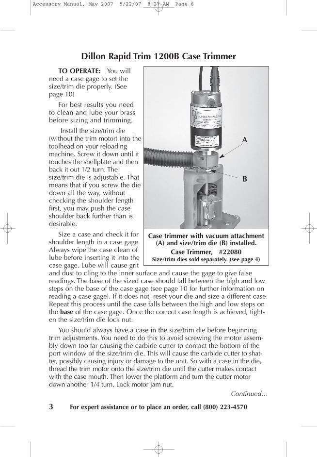
Dillon Rapid Trim 1200B Case Trimmer
Case trimmer with vacuum attachment(A) and size/trim die (B) installed.
Case Trimmer, #22080Size/trim dies sold separately. (see page 4)
A
B
3
Accessory Manual, May 2007 5/22/07 8:27 AM Page 6
Dillon Rapid Trim 1200B Case Trimmer
Connect the power cords and turn themotor on.
Trim a case and check it for overall lengthin a case gage. To check for overall length, setthe case firmly into the case gage and set thegage on a clean, flat surface. The case mouthshould be between the high and low step ofthe case gage (see page 10 for further infor-mation on reading a case gage).
Adjust the motor up or down and repeatthese steps until the right overall length isachieved. Once the right length is reached,lock the motor jam nut. Before turning theunit on, always retighten the motor jam nut.
NOTE: The vacuum assembly clampsaround the lower bell of the trimmer motorassembly. It should surround the chip exhaustport on the trim die. The vacuum attachmentmay need to be modified to fit your vacuumcleaner model.
Now that your cases have beentrimmed to length, you’ll need todecap them and expand the casemouth. To do this properly youneed to make sure that the sizingdie does not contact the shoul-der of the case and change theheadspacing. To prevent thisfrom happening, thread the sizedie down until it makes contactwith the case and then back it up1/2 a turn and lock in place.
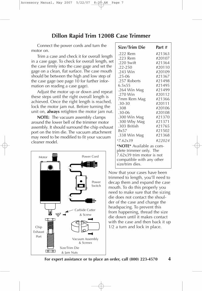
Size/Trim Die Part #.222 Rem #21363.223 Rem #20107.220 Swift #21364.22-250 #20110.243 Win #20109.25-06 #21367.257 Roberts #214986.5x55 #21495.264 Win Mag #21499.270 Win #201127mm Rem Mag #21366.30-30 #20111.308 #20106.30-06 #20108.300 Win Mag #21370.300 Wby Mag #21371.303 British #217658x57 #21502.338 Win Mag #21368*7.62x39 #22024*NOTE* Available as com-plete trimmer only. The7.62x39 trim motor is notcompatible with any othersize/trim dies.
Power Cord
Chip Exhaust
Port
Motor
Power Switch
Vacuum Assembly & Screws
Carbide Cutter& Screw
Size/Trim Die& Jam Nuts
For expert assistance or to place an order, call (800) 223-4570 4
Accessory Manual, May 2007 5/22/07 8:27 AM Page 7

5 For expert assistance or to place an order, call (800) 223-4570
Most military brass has acrimped primer pocket and there-fore requires swaging. The crimpmust be removed prior to reprim-ing and reloading the case.
TO OPERATE: First make sureall of your brass has beendeprimed.
Use the proper diameter caselocator rod. The unit comes withthe .223 rod installed. The largerrods are for .30 cal, .38 and 9mm. For .45 ACP, use the bushing(not pictured) over the .30 caliberrod.
Use the proper swage rod.The smaller primer swage rod isinstalled at the factory. (See page6 for parts identification.)
To change swage rods:Pry off an “E” clip from either side of the eccentric pin. Slide the eccentric pin out and remove the handle/swage rod assembly.Using a pencil or similar object, push out the toggle dowel pin.Put a light coating of grease over the entire surface of the proper size
swage rod and re-assemble. When re-assembling the unit, be sure theeccentric pin is on top of the handle in the eccentric, otherwise you won’tbe able to make a complete stroke.
Now set a case on the locator rod. Screw the locator rod in or out sothat the case goes down without hitting the back-up plate.
Slowly push the handle down and move the case so that the tip of theswage rod enters the primer pocket.
Leave the swage rod in the primer pocket and lock the set screw on theright side of the swager unit. This locks the location of the flat block. The flatblock sets the alignment of the primer pocket with the swage rod. Failure todo this will ruin your case and may damage the swager itself.
Adjustment for the proper amount of swage is done by trial and error.Not enough swage and the primers won’t seat fully. Too much swage willstress the unit, possibly bending the locator rod.
Continued…
Dillon SS-600 Super Swager
SS-600 Super Swager, #20095
Accessory Manual, May 2007 5/22/07 8:27 AM Page 8

Detent Set Screw,Detent Spring,and Detent Ball.
SwagerBody
Swage Rod(Large Rod Pictured)
SwagerHandle
ToggleKnob
EccentricEccentric Pin
E-clips
Flat Block
Toggle Dowel PinBack-up Plate
Flat Block Set ScrewCover and Cover ScrewsCase Locator Rod(Small Rod Pictured)
Lever
Lever Pin
For expert assistance or to place an order, call (800) 223-4570
Dillon SS-600 Super SwageA properly swaged pocketshould have a smooth radius(see photograph B). Set thelocator rod for minimal swageand swage a case. Examine theedge of the primer pocket to besure it is smooth, then seat aprimer in it. Repeat this processuntil enough swage is achieved to seat a primer easily.
NOTE: Re-adjustment of the locator rod may be required when swag-ing brass from different manufacturers or different lots due to different casewebbing.
When changing calibers, the flat block will need to be re-adjusted,.223 has a different case diameter than 9mm, etc. So repeat the steps nec-essary for proper adjustment.
SPECIAL NOTE FOR 38 SUPER BRASS: Whenever it becomes neces-sary to swage 38 super brass that has been hot-loaded, be sure to select acase that is brand new when making adjustments. These cases have asmuch primer pocket radius as you would ever want, so adjust your caselocator rod with a brand new case and then try some fired/deprimedcases.
IMPORTANT: When mounting the Super Swager to your loadingbench, make sure that the handle can extend below the edge of thebench. This is necessary to achieve a complete stroke.
6
Photo “B”: The case on the left shows aproperly swaged primer pocket.
Accessory Manual, May 2007 5/22/07 8:27 AM Page 9

How to use the Case Gage:The way the case gage works is
this: Once you’ve made a prelimi-nary adjustment to your sizing diedrop the sized case all the way intothe case gage, Fig 1. Look at thebase of the case.
If the base of the case is belowthe high step (see “B” Fig 2) andabove the low step (see “A” Fig 2)then the sizing die is properlyadjusted. If the base of the case isabove the high step Fig 3, then youwill need to adjust the sizing diedown by turning it clockwise.
If the base at the case is belowlow step Fig 4, then the sizing dieis adjusted down too far and needsto be backed out by turning itcounter-clockwise (Note: this caseshould be thrown away).
Once the sizing die is properlyadjusted, drop the properly sizedcase back into the case gage andlook at the mouth of the case, Fig5. If the case mouth is below thehigh step (see “C” Fig 5) and abovethe low step (see “D” Fig 5) thenthe case is the proper length andwill not need to be trimmed. If thecase mouth is above the high stepFig 6, then the case mouth needs tobe trimmed in order to reduce theoverall length of the case.
If you find that your cases needto be trimmed, Dillon Precisionoffers two types of case trimmers.
7
Dillon Case Gages
��������������������������������
Figs 72 & 73 Fig 74 Fig 75 Fig 76 Fig 77
��������������������������������
Figs 72 & 73 Fig 74 Fig 75 Fig 76 Fig 77
A B
��������������������������������
Fig 3
A B
Alow step
Bhigh step
For expert assistance or to place an order, call (800) 223-4570
Fig 2
Dhigh step
Clow step
Fig 1
��������������������������������
��������������������������������
��������������������������������
Fig 4
Fig 5
Fig 6
C D
C D
A B
Accessory Manual, May 2007 5/22/07 8:27 AM Page 10

Dillon Case Gages, cont…NOTE: Before
inserting any case intoa case gage, make sureit is wiped clean of anylubricant. Otherwise,the lubricant will accu-mulate inside the casegage and cause it tobecome coated withgrit and dust. This willcause the case gage togive inaccurate read-ings. Always refer to areliable loading manualfor case dimensions.
RIFLE case gages have “steps” on the top and base. If a case is properlytrimmed and the shoulder setting is correct, the case should fall between thehigh and low steps. These two settings are accomplished at different stages ofreloading.
Shoulder setting is done at station one of your loading machine. When acase has a proper shoulder setting it will fall between the high and low stepsat the BASE of the case gage. If it falls below the low step, you need to raiseyour sizing die up in 1/8 turn increments until the proper setting is achieved.If the case is above the high step, you need to lower the sizing die.
Overall length, or OAL, is done while trimming fired rifle cases back downto size. Insert a CLEAN case into the gage and set it on a clean, flat surface. Ifthe case is trimmed properly, the mouth of the case will be between the highand low steps at the TOP of the gage. If the mouth of the case is above thehigh step, you need to turn your trim motor down in small increments untilthe proper OAL is reached. If the rim is below the low step, you need to raisethe trim motor. Refer to trimmer instructions.
PISTOL case gages do not have the stepsmentioned in the rifle gage section. The pistolgage is used to determine overall length andcase diameter. Designed to maximum SAAMIcartridge length and minimum chamber diame-ter. OAL is achieved by seating the bullet to theproper depth at station three of your loadingmachine.
Insert a completed round into the gage and setit on a clean, flat surface. If the bullet extendsfrom the top of the gage, the round is too long. Toseat the bullet deeper into the case, adjust yourseating die down in 1/8 turn increments until theproper OAL is achieved.
.380 ACP #151609 mm #15161.38 Super #15158.38 Special #15159.357 Mag. #15163.40 S&W #1516410 mm #15162.44 Mag. #15165.45 ACP #15166.45 Colt #15167.223 #13254.308 #12867.30-06 #12679
8For expert assistance or to place an order, call (800) 223-4570
Accessory Manual, May 2007 5/22/07 8:27 AM Page 11

For expert assistance or to place an order, call (800) 223-4570
Kinetic Bullet Puller
Kinetic Bullet Puller, #17999
IMPORTANT
For use on CENTERFIRE CARTRIDGES only. Not for use with rimfirecartridges or explosive-projectile ammunition.
Before you begin make sure the FLAT side of the metal chuck assemblysits on the flat surface of the puller body and the cap is threaded on. Alsonote that the rubber strip is crimped to the chuck jaws, it is not a ring.
TO OPERATE: Loosen the cap until the chuck inside of the cap loosensenough to easily insert a round. Insert and rotate the cartridge until thechuck engages the extractor groove or contact is made on a rimmed car-tridge. Now tighten the cap.
Grip the handle mainly with your thumb and forefinger. Easy extractionresults from the handle shaft being PARALLEL to the striking surface AT THEMOMENT OF IMPACT. This also protects the plastic head from breaking.Rap the nose of the bullet puller against a hard, solid surface. If more thanone rap is necessary to extract the bullet, retighten the cap after each rap.
Remove the cap to retrieve the components.
NOTE: To protect the lead tips on soft-point bullets you may wantto place a foam ear plug into the nose of the bullet puller prior tousing the bullet puller.
Nose
Cap Chuck
9
Accessory Manual, May 2007 5/22/07 8:27 AM Page 12

10For expert assistance or to place an order, call (800) 223-4570
TO OPERATE: Be sure that the gold-colored powder pan is set on topof the silver-colored pan support before zeroing the scale.
The scale has three poises: 0 - 500 grains in 10 grain increments; 0 -10 grains in 1 grain increments; 0 - 1 grain in .1 grain increments. Besure that the poises are all set at zero before leveling the beam with thewhite plastic leveler foot.
Make sure that the end loop on the balance beam has not been bent ortwisted. This is the loop that the powder pan hangs from. The loop mustmove freely.
Inspect the copper damper vane to make sure it is not bent. It shouldbe centered in the notch.
Do not use any lubricant on any part of the scale. Keep all surfacesclean and free of corrosion.
Dillon Eliminator Scale
Eliminator Scale, #13480
PoisesCopper Damper Vane End Loop
Leveler Foot
Accessory Manual, May 2007 5/22/07 8:27 AM Page 13

11
Square Deal Cartridge Bin #1375610 Pack Blue Bins #2091324 Pack Blue Bins #2091448 Pack Blue Bins #20952RL550/XL650 Cartridge Bin#1383910 Pack Blue Bins #2091724 Pack Blue Bins #2091848 Pack Blue Bins #20953
RL1050 Cartridge Bin #134846 Pack Blue Bins #2091512 Pack Blue Bins #2091624 Pack Blue Bins #20954SL900 Cartridge Bin #171256 Pack Blue Bins #9704212 Pack Blue Bins #9704324 Pack Blue Bins #20954
Dillon Akro Bins and Utility Boxes
For expert assistance or to place an order, call (800) 223-4570
Akro Bins
Dillon Utility BoxesThese boxes can be used for any
household purpose. They can hold any-thing from fishing tackle to a SquareDeal B conversion.Large Utility Box #17195Five Large Boxes #97067Small Utility Box #13636Five Small Boxes #20925Ten Small Boxes #20926
Accessory Manual, May 2007 5/22/07 8:27 AM Page 14
For expert assistance or to place an order, call (800) 223-4570
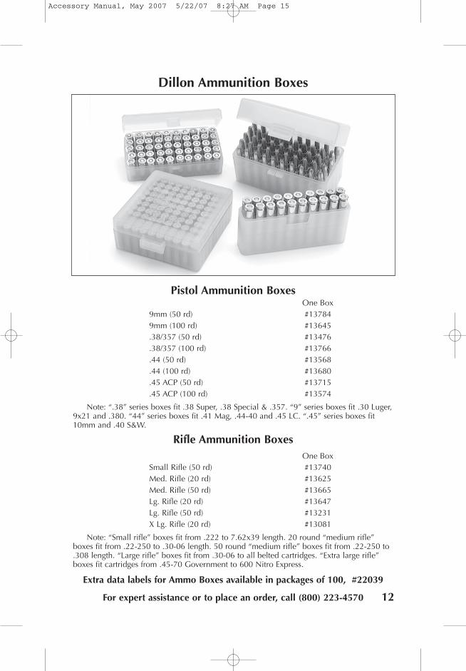
Dillon Ammunition Boxes
Pistol Ammunition BoxesOne Box
9mm (50 rd) #137849mm (100 rd) #13645.38/357 (50 rd) #13476.38/357 (100 rd) #13766.44 (50 rd) #13568.44 (100 rd) #13680.45 ACP (50 rd) #13715.45 ACP (100 rd) #13574
Note: “.38” series boxes fit .38 Super, .38 Special & .357. “9” series boxes fit .30 Luger,9x21 and .380. “44” series boxes fit .41 Mag, .44-40 and .45 LC. “.45” series boxes fit10mm and .40 S&W.
Rifle Ammunition BoxesOne Box
Small Rifle (50 rd) #13740Med. Rifle (20 rd) #13625Med. Rifle (50 rd) #13665Lg. Rifle (20 rd) #13647Lg. Rifle (50 rd) #13231X Lg. Rifle (20 rd) #13081
Note: “Small rifle” boxes fit from .222 to 7.62x39 length. 20 round “medium rifle”boxes fit from .22-250 to .30-06 length. 50 round “medium rifle” boxes fit from .22-250 to.308 length. “Large rifle” boxes fit from .30-06 to all belted cartridges. “Extra large rifle”boxes fit cartridges from .45-70 Government to 600 Nitro Express.
Extra data labels for Ammo Boxes available in packages of 100, #22039
12
Accessory Manual, May 2007 5/22/07 8:27 AM Page 15

For technical assistance or orders:(800) 223-4570
To place an order by stock numbers or to quickly check the status of an order only.
No technical questions please:(800) 762-3845
To order The Blue Press catalog:(800) 762-3844
NOTE: Before sending any item in for repair you must con-tact us for a Return Merchandise Authorization, or RMA num-
ber. This number will help expedite service.
8009 E. Dillon’s WayScottsdale, AZ 85260
(480) 948-8009Fax: (480) 998-2786
illonrecision
Products, Inc.
Manufacturers ofthe World’s FinestLoading Equipment
Accessory Manual, May 2007
Accessory Manual, May 2007 5/22/07 8:27 AM Page 16