Instruction Manual Juki AMS-210E
243
40034836 No.E369-02 ENGINEER’S MANUAL Computer-controlled, Cycle Machine With Input Function AMS-210E Series ®
-
Upload
anonymous-inxlbbu5b -
Category
Documents
-
view
163 -
download
21
description
Instruction Manual Automatik Program Pattrun Juki AMS 210E
Transcript of Instruction Manual Juki AMS-210E

40034836No.E369-02
ENGINEER’S MANUAL
Computer-controlled, Cycle MachineWith Input Function
AMS-210E Series
®

PREFACE
This Engineer’s Manual is written for the technical personnel who are responsible for the service and maintenance
of the machine.
The Instruction Manual for these machines intended for the maintenance personnel and operators at an apparel
factory contains operating instruction in derail. And this manual describes “Standard Adjustment”, “Adjustment
Procedures”, “Results of Improper Adjustment”, and other important information which are not covered in the
Instruction Manual.
It is advisable to use the Input Instruction Manual, relevant Instruction Manual and Parts List together with this
Engineer’s Manual when carrying out the maintenance of these machines.
In addition, for the motor for the sewing machine with thread trimmer, refer to the separate Instruction Manual or
This manual gives the “Standard Adjustment” on the former page under which the most basic adjustment value is
described, and on the latter page “Results if Improper Adjustment” under which stitching errors and troubles
arising from mechanical failures and “Hoe to adjust” are described.

CONTENTS
1. Specifications ........................................................................................................ 1
2. Configuration........................................................................................................... 2(1) Names of main unit .................................................................................................................. 2(2) IP-400 operation panel ............................................................................................................. 3(3) CP-20 operation panel ............................................................................................................. 4
3. Standard adjustment .............................................................................................. 5(1) Main shaft connection/disconnection .................................................................................. 5(2) Removal of main shaft motor and coupling ......................................................................... 7(3) Crank rod connection/disconnection ................................................................................... 9(4) Crank balancer positioning ................................................................................................. 11(5) Adjustment of intermediate presser cam ........................................................................... 13(6) Adjustment of intermediate presser bar............................................................................. 13(7) Intermediate presser variable connection /disconnection ............................................... 15(8) Intermediate presser variable adjustments........................................................................ 17(9) Intermediate presser drivie arm .......................................................................................... 19(10) Lower shaft backlash adjustment and connection/disconnection .................................. 21(11) Oscillator gear positioning .................................................................................................. 21(12) Adjustment of hook oil amount ........................................................................................... 23(13) Shuttle connection / disconnection and oil wick piping ................................................... 23(14) Adjusting the height of the needle bar ............................................................................... 25(15) Hook adjustment................................................................................................................... 27(16) Thread trimmer presser lifter cam connection/disconnection ........................................ 29(17) Thread trimmer and presser origin sensor adjustment ................................................... 29(18) Adjusting the thread trimmer sensor ................................................................................. 31(19) Adjustment of the moving knife and counter knife position ............................................ 33(20) Floating amount of the thread tension disk ...................................................................... 33(21) Second thread tension connection / disconnection ......................................................... 35(22) AT unit connection / disconnection .................................................................................... 37(23) Wiper adjustment ................................................................................................................. 39(24) Adjusting the pre-load of the X-Y table .............................................................................. 41(25) Adjustment of the tension of the X timing belt .................................................................. 43(26) Adjustment to positions of X-motor and Y-motor (Backlash adjustment to gear) ......... 43(27) Adjusting of the presser lower arm (Motor type only) ...................................................... 45(28) Adjustment when the presser plate sheet is replaced (Motor type only) ....................... 45(29) Height of the slider and pasting of the presser plate sheet
(Pneumatic type only) .......................................................................................................... 47(30) Adjusting the speed of the work clamp feet (Pneumatic type only) ................................ 49(31) Making the origin setting gauge ......................................................................................... 51(32) Adjusting the X origin sensor ............................................................................................. 51(33) Adjusting the Y origin sensor ............................................................................................. 53(34) Adjustment of the bobbin winder driving wheel position ................................................ 55(35) Adjusting the bobbin winder amount ................................................................................. 55(36) Adjustment of the shuttle upper spring and lower thread holder position .................... 57(37) Shuttle felt ............................................................................................................................. 57(38) Shape of the shuttle race ring ............................................................................................. 59(39) Adjustment of thread take-up spring ................................................................................. 59(40) Needle thread clamp device connection/disconnection .................................................. 61(41) Adjusting the needle thread clamp sensor ........................................................................ 63(42) Adjusting the needle thread clamp notch .......................................................................... 65
4. Memory switch ...................................................................................................... 67(1) Start and change .................................................................................................................... 67(2) Function list ............................................................................................................................ 69

5. Supplemental remarks of each function number and explanation of each function ............................................................................... 92
(1) Feeding frame operational sequence setup ........................................................................ 92(2) Fixed refuge position setup .................................................................................................. 96(3) Bank function setup ............................................................................................................... 97(4) Port I/O setup ........................................................................................................................ 101(5) Simplified program setup .................................................................................................... 112(6) Version display ..................................................................................................................... 126(7) Keylock setup ....................................................................................................................... 127(8) Communication screens of the maintenance personnel level (Program rewrite) ......... 128(9) Information screen at the maintenance personnel level .................................................. 134(10) Test sewing function ......................................................................................................... 136
6. Test mode ........................................................................................................... 139(1) Start (CP-20) ......................................................................................................................... 139(2) Display output test (CP-20) ................................................................................................. 141(3) Method of confirmation according to each test program No. (CP-20) ............................ 142(4) For IP-400 .............................................................................................................................. 149
7. Printed wiring board and dip switch ................................................................ 165(1) Various printed wiring boards ............................................................................................ 165(2) Dipswitch setup .................................................................................................................... 173
8. Table of exchanging gauge parts according to sewing specifications andneedle size used ................................................................................................ 174
9. Option list ........................................................................................................... 175(1) Method of pedal switch cable set connections ................................................................. 182(2) Method of mechanical valve unit connections .................................................................. 184
10. Maintenance ....................................................................................................... 185(1) Replacing the fuse ............................................................................................................... 185(2) Changing the voltage specification .................................................................................... 186(3) Greasing • lock-tight parts .................................................................................................. 187(4) Parts to which grease • lock-tight is applied ..................................................................... 188(5) Replenishing the designated places with grease ............................................................. 196
11. Error code list .................................................................................................... 198
12. Message list ....................................................................................................... 205
13. Troubles and corrective measures .................................................................. 208(1) Mechanical parts .................................................................................................................. 208(2) Sewing conditions ............................................................................................................... 212(3) Electrical components ......................................................................................................... 220
14. Circuit diagrams ................................................................................................ 228(1) Block diagram A ................................................................................................................. 228(2) Power supply circuit diagram A ........................................................................................ 229(3) Power supply circuit diagram B ........................................................................................ 230(4) Power supply circuit diagram C ........................................................................................ 231(5) Servo motor circuit diagram .............................................................................................. 232(6) Sensor-pedal circuit diagram ............................................................................................ 233(7) MAIN•PANEL board circuit diagram ................................................................................. 234(8) Motor•solenoid circuit diagram ......................................................................................... 235(9) Air system circuit diagram................................................................................................. 236
15.Drawing of the table ........................................................................................... 237

– 1 –
No. Application
AMS-210EHS AMS-210ESS AMS-210EHL AMS-210ESL AMS-210EHL AMS-210ESL AMS-210EHL AMS-210ESL AMS-210EHL AMS-210ESL
Sub-class 1306 1510 2206 2210
1 Sewing area X-Direction (right, left) 130mm; Y-Direction (forward, backward) 60mm X-Direction (right, left) 150mm; Y-Direction (forward, backward) 100mm X-Direction (right, left) 220mm; Y-Direction (forward, backward) 60mm X-Direction (right, left) 220mm; Y-Direction (forward, backward) 100mm
2 Max. sewing speed 2700rpm (when sewing pitch is 3mm or less)
3 Stitch length 0.1 to 12.7mm (Min. resolution : 0.05mm)
4 Feed motion of feeding frame intermittent feed (2-shaft drive by stepping motor)
5 Needle bar stroke 41.2mm
6 Needle S type: DP x 5 # 14, H type: DP x 17 # 18
7 Method to lift feeding frame Pulse motor Air
8 Feeding frame shape Right and left united Right and left separated Right and left united
9 Lift of feeding frame Standard 25mm, Max. 30mm Max. 30mm
10 Intermediate presser stroke Standard 4mm (0 to 10mm)
11 Lift of intermediate presser 20mm
12 Intermediate presser Standard 0 to 3.5mm (Max. 0 to 7.0mm)DOWN position variable
13 Needle thread clamp device H type S type H type S type H type S type H type S type H type S type
14 Needle thread tension Active tension (electronic thread tension control mechanism)
15 Hook 2-fold semi-rotary hook
16 Lubrication Plane part: grease, hook part: minute volume lubrication (tank type)
17 Lubricating oil JUKI NEW Defrix oil (equivalent to ISO VG32) (Lubrication system)
18 Grease 1. Penetration No. 2 lithium grease, 2. Templex N2, 3. Juki Grease A, 4. Juki Grease B (Caution)1.
19 EEP-ROM, Smart mediaMemory of pattern data • EEP-ROM : Max. 200 patterns (Max. 20,000 stitches/pattern)
• Smart media : Max. 999 patterns (Max. 50,000 stitches/pattern)
20 Temporary stop facility Used to stop machine operation during a stitching cycle.
21 Enlarging/Reducing Allows a pattern to be enlarged or reduced on the X axis Y axis independently when sewing a pattern.function Scale : 1% to 400% times (0.1% steps)
22 Enlarging/Reducing Pattern enlargement / reduction can be done by increasing / decreasing either stitch length or the number of stitches.method (Only increase/decrease of stitch length when pattern button is selected and CP-20 is used)
23 Sewing speed limitations 200 to 2,700 rpm (Scale : 100 rpm steps)
Pattern No. selection method24 Pattern selector facility (EEP-ROM : 1 to 200, Smart media : 1 to 999)
(CP-20 is the scroll type.)
25 No. of sheets counter Up/Down method (0 to 9,999) (IP-400 only)
26 Sewing counter Up/Down method (0 to 9,999)(Bobbin thread counter)
27 Memory back-up In case of a power interruption, the pattern being used will automatically be stored in memory.
28 2nd origin setting facility Using jog keys, a 2nd origin (needle position after asewing cycle) can be set in the desired position within the sewing area.The set 2nd origin is also stored in memory. (IP-400 only)
29 Sewing machine motor Servomotor 550W
30 External dimensions 1,200mm (W) x710mm (L) x 1,200mm (H) 1,200mm (W) x770mm (L) x 1,200mm (H) 1,200mm (W) x710mm (L) x 1,200mm (H) 1,200mm (W) x770mm (L) x 1,200mm (H)(Excluding thread stand) (Excluding thread stand) (Excluding thread stand) (Excluding thread stand)
31 Weight (gross weight) Machine head : 69kg, Control box : 16.5kg Machine head : 73kg, Control box : 16.5kg Machine head : 75kg, Control box : 16.5kg Machine head : 77kg, Control box : 16.5kg
32 Power consumption 500VA
33 Working temperature/humidity Temperature: 5-35°C, Humidity: 35-85% (no condensation)
34 Supply voltage/frequency Rated voltage ±10% 50 / 60Hz
35 Air pressure used — Standard: 0.35 to 0.4MPa, Max. 0.55MPa
36 Air consumption — 1.8dm3 /min (ANR)
37 Needle highest position After the completion if sewing, the needle can be brought up to its highest position.
stop facility
1. SpecificationsModel name
Item
(Caution) Grease type, refer to (3) Greasing • lock-tite parts of [10] Maintenance

MEMO

2. Configuration(1) Names of main unit
Machine head
Wiper switch
Temporary stop switch
Feeding frame
Intermediate presser
Thread stand
Operation panel (IP-400 or CP-20)
Power switch
Control box
Foot pedal
Manual pedal (Excluding pneumatic type)
– 2 –
Air regulator
(for pneumatic type only)

(2) IP-400 operation panel
(Front view) (Right side view)
– 3 –
Touch panel • LCD display section
READY key → Changeover of the data input screen and the sewing screen can beperformed.
INFORMATION key → Changeover of the data input screen and the information screen canbe performed.
COMMUNICATION key → Changeover of the data input screen and the communication screencan be performed.
MODE key → Changeover of the data input screen and the mode changeover screenwhich performs various detail settings can be performed.
Smart media card slot (Close the cover for use.)
Connector for RS-232C communication
Variable resistor for color LCD → Screen contrast can be adjusted. Adjust it as you desire.
Connector for external input

Item selection LEDLEDs of the selected items light up.
Needle thread clamp ON/OFF keyThis key selects effective/ineffective of needle threadclamp. When it is effective, needle thread clampdisply LED lights up.
Needle thread clamp display LEDWhen this LED lights up, needle threas clampoperaters.
Pattern registration keyThis key registers the pattern. When this key ispressed, the pattern registered here can sew imme-diately.X/Y scale, sewing position. etc. can be changed andregistered.
(3) CP-20 operation panel
Pattern No. X scale Y scale
Max. speed Sewing Bobbin limitation counter winder
Intermediate Thread tensionpresser height
– 4 –
“Ready” keyThis key changes over the setting state from the panelto the sewing state where the sewing machine actu-ally operates.
Sewing LEDThis LED goes off at the time of setting state andlights up at the time of sewing state. Changeovercan be performed with “Ready” key.
“Reset” keyThis key is used for canceling error or returning theset value to the initial value.
“Mode” keyThis key makes the setting mode of the memoryswitch.
“+ / Feed forward” key and “- / Feed backward”keyThis key is used for changing pattern No. and X/Yscale, and feed forward/feed backward.
“Selection” keyThis key selects the item to be set. Item selectionLED of the selected item and the set value are dis-played.
Data indication LEDThis LED indicates the set values of the selecteditems such as pattern No., X/Y scale, etc.
CP-20

3. Standard adjustment(1) Main shaft connection/disconnection
1. Loosen the set screw securing the main shaft counterbalance , and remove the taper screw .2. Loosen 2 set screws (through the screwdriver hole A), 2 set screws , and 2 set screws .
On this occasion, loosen No. 2 set screw first, and completely remove No. 1 set screw from the flat part of themain shaft .
3. Remove the main shaft motor .Refer to “3.-(2) Removal of the main shaft motor and coupling”.
4. Loosen 2 set screws .On this occasion, be aware that the balancer may rotate due to loosened set screws .
5. Loosen 2 set screws .6. Loosen 2 set screws .
On this occasion, completely remove No. 1 set screw of the set screws from the flat part of the main shaft.
7. Loosen 2 set screws and 2 set screws .8. Pull out the main shaft in the direction of Arrow C.
– 5 –
Screwdriver hole A
No. 1 set screw
No. 2 set screw
No. 2 set screw
No. 2 setscrew
No. 1 set screw
No. 1 set screw
D
F
E
C
Procedures of disassembling
Main shaft taper hole

1. Insert the main shaft into the crank rod , balancer , hand pulley gear A , bobbin winding drivewheel , and main shaft counterbalance in this order, and mount this assembly on the frame.
2. Tighten the taper screw into the taper hole of the main shaft , and tighten the set screw to securethe main shaft counterbalance .
3. Lightly press the main shaft counterbalance in the direction of Arrow D and the middle metal in thedirection of Arrow E, and tighten 2 set screws .(Tighten No. 1 set screw so that it touches the flat part of the main shaft . Then, tighten No. 2 set screw.Same procedure hereafter)
4. Tighten 2 set screws and 2 set screws . (Make sure that No. 1 set screw touches the flat part of themain shaft .)
5. Press the hand pulley in the direction of Arrow F to engage the hand pulley gear A with the hand pulleygear B , and secure them with 2 set screws .
6. Mount the main shaft motor and coupling .Refer to “3.-(2) Removal of main shaft motor and coupling”.
7. Secure the eccentric cam of the intermediate presser with 2 set screws . Refer to “3.-(5) Adjustmentof intermediate presser cam”.
8. Secure the crank rod with 2 set screws . Refer to “3.-(3) Crank rod connection/disconnection”.9. Secure the balancer with 2 set screws . Refer to “3.-(4) Crank balancer positioning”.10. Secure the bobbin winding drive wheel with 2 set screws . Refer to “3.-(34) Adjustment of the bobbin
winder driveing wheel poition”. * Make sure that no torque is applied by rotating the main shaft .
– 6 –
Procedures of assembling
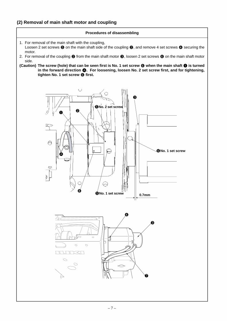
(2) Removal of main shaft motor and coupling
1. For removal of the main shaft with the coupling,Loosen 2 set screws on the main shaft side of the coupling , and remove 4 set screws securing themotor.
2. For removal of the coupling from the main shaft motor , loosen 2 set screws on the main shaft motorside.
(Caution) The screw (hole) that can be seen first is No. 1 set screw when the main shaft is turnedin the forward direction AAAAA . For loosening, loosen No. 2 set screw first, and for tightening,tighten No. 1 set screw first.
No. 1 set screw
No. 1 set screw
0.7mm
A
– 7 –
No. 2 set screw
Procedures of disassembling

1. For mounting the main shaft motor with the coupling,(1) Tighten 4 set screws that securing the motor, and tighten 2 set screws on the main shaft side of the
coupling .(2) The cords of the main shaft motor should be positioned in the lateral direction.
2. For connecting the coupling to the main shaft motor,(1) Provide a clearance of 0.7 mm between the coupling and main shaft motor .(2) Apply No. 1 set screw of the coupling to the flat section of the main shaft motor , the main
shaft and secure it.3. For engaging the coupling,
(1) Position the set screw (No. 1 set screw) on the main shaft motor side between 2 set screws on themain shaft side, and engage the coupling.
– 8 –
Procedures of assembling

(3) Crank rod connection/disconnection
1. Loosen 3 set screws and 2 set screws . On this occasion, loosen No. 2 set screws first, and completelydisengage No. 1 set screws from the flat section of the oscillator shaft .
2. Pull out the oscillator shaft in the direction of Arrow A.3. Remove the main shaft according to “3.-(1) Main shaft connection/disconnection”, and remove the crank
rod unit .
– 9 –
22.1 to 22.6mm
Face B No. 2 set screw
No. 1 set screw
C
A
E
D
Procedures of disassembling
No. 1 set screw
No. 2 set screw

1. Mount the main shaft according to “3.-(1) Main shaft connection/disconnection”, and mount the crank rodunit .
2. Adjust the clearance to 22.1 to 22.6 mm between the under cam of the crank rod unit and Face B(middle metal bearing mounting face) of the frame, and secure the cam with the set screw .(Apply No. 1 set screw to the flat section of the main shaft and tighten it first, then tighten No. 2 set screw.Same procedure hereafter)
3. Pass the oscillator through the oscillator shaft , and mount them on the frame.4. Pass the thrust collar through the oscillator shaft . Lightly press the oscillator shaft in the direction of
arrow C and the thrust collar in the direction of Arrow D, and tighten 2 set screws . Make sure that No.1 set screw touches the flat section of the oscillator shaft .)
5. Secure the oscillator according to “3.-(11) Oscillator gear positioning”.(Caution) 1. Make sure that no torque is applied by rotating the main shaft .
2. When the crank rod unit is connected, disconnected, or positioned, or the oscillator is positioned, be sure to grease two specified positions and the gear section (E) of theoscillator .
3. After positioning the crank rod unit (under cam ), be sure to perform “3.-(11) Oscilla-tor gear positioning”. Wrong positioning of the under cam or oscillator may causefrictional wear or lock-up.
– 10 –
Procedures of assembling

(4) Crank balancer positioning
[Rotating direction]When the needle bar lowers and the clearance between the needle bar connecting and needle bar lowerbushing is 4.6 mm, 2 set screws of the crank balancer becomes horizontal position.
[Axial direction]Bring the main shaft eccentric cam into contact with the crank balancer .
– 11 –
Standard Adjustment
4.6mm
B
A

If the main shaft eccentric cam is not secured, the main shaft eccentriccam should be positioned first.1. Loosen 2 set screws securing the crank balancer .2. Remove 4 set screws , then remove the crank rod cover .3. Turn the main shaft in the forward direction A so that the needle bar
lowers and the clearance between the needle bar connecting and needle bar lower bushing is 4.6 mm.
4. Secure the crank balancer with 2 set screws under the condi-tions that 2 set screws securing the balancer are horizontallypositioned and the balancer is moved in the direction of Arrow B
to make it into contact with the main shaft eccentric cam . Fortightening 2 set screws , tighten them alternately.
– 12 –
Adjustment Procedures Results of Improper Adjustment
o If the mounting angle of the crankbalancer is wrong, vibrationduring sewing will be intensified.
o If the sewing machine is used fora long time under the condition ofwrong securing position, the lifeof main shaft bearing may beshortened.
o If the crank balancer is notmoved in the direction of ArrowB , it may interfere with the sew-
ing machine frame.

(5) Adjustment of intermediate presser cam
– 13 –
(6) Adjustment of intermediate presser bar
13.5
mm
Standard Adjustment
Standard Adjustment
Align
Align

1. Align the edge of the intermediate presser cam with the center ofthe engraved point on the main shaft , align the engraved line onthe intermediate presser cam with the engraved point on the mainshaft , and tighten the set screw .
o Stitch skipping and poor tensestitch may occur.
– 14 –
1. Adjust the thrusting distance of the intermediate presser bar to13.5 mm, and tighten the set screw after ensuring that the needlepasses through the center of the intermediate pressure.
(Caution) Be aware that the tightening pressure of the set screwshould be from 2.16 to 2.75 N•m (22 to 28 kgf•cm).
o An excessive thrusting distance ofthe intermediate presser bar may damage the intermediatepresser spring or cause poorpresser lifting.
o Excessive tightening pressuremay deform the intermediatepressure bar or intermediatepresser bar connect ing resulting in malfunction.
Adjustment Procedures Results of Improper Adjustment
Adjustment Procedures Results of Improper Adjustment

A
27.0
mm
Right above
45°
B
E
0.5m
m
C
H
D
4.4mmF
Fig J
(7) Intermediate presser variable connection/disconnection
– 15 –
Procedures of disassembling
No. 1 set screw
No. 1 setscrew
No. 1 setscrew
1. Remove the presser adjusting screw . Then, remove the intermediate presser spring and the guide shaft.2. Remove the intermediate presser auxiliary spring .3. Remove the step screws , , and .4. Remove the step screw .5. Remove the step screw , and then the intermediate presser variable plate and the variable plate
spacer .6. Remove the step screw , and then the intermediate presser variable link .
(At that time, insert a hexagonal wrench through the arm screw hole A and apply it to the setscrew as ameans of turn stop for the intermediate presser variable arm .)
7. Loosen two each of the setscrews , , and .At that time, the second screw should be loosened first. The first screw of the setscrew should be removed,completely separate from the flat part of the intermediate presser variable shaft .
8. After the intermediate presser variable arm and the intermediate presser variable shaft have beenpulled out in the direction of the Arrow B, loosen the setscrew and pull out the intermediate presservariable shaft from the intermediate presser variable arm .At that time, both of the setscrews should be separated completely from the flat parts (2 positions) of theintermediate presser variable shaft .
9. Loosen the two setscrews and remove the intermediate presser coupling , the intermediate pressermotor mounting plate , and the intermediate presser motor .
10. Loosen two each of the setscrews , , and .At that time, the second screws of the setscrews and should be loosened first. The first screw of thesetscrew should be removed, completely separate from the flat part of the intermediate presser lifting shaft
.11. Remove the E ring and pull out the intermediate presser lifting shaft in the direction of the Arrow C.
193.8mm
G

– 16 –
Procedures of assembling
1. Fix the intermediate presser variable shaft to the intermediate presser variable arm by means of thetwo setscrews so that the length of the shaft section becomes 193.8mm.(Both setscrews should be adjusted level to the intermediate presser variable shaft .)
2. Insert the washer , thrust bearing , thrust collar , and the drive bevel gear in the intermediatepresser variable shaft in this order, and mount this assembly on the frame.
3. Pressing the intermediate presser variable arm in the direction of the Arrow E, secure a proper thrust bypressing the thrust collar in the direction of the Arrow D and tighten the two setscrews . (Tighten thefirst screw first so that it is fixed level to the intermediate presser variable shaft . Then, tighten the secondscrew. To be done in the same manner hereafter.)
(Caution) If there is rattle in the variable shaft of the intermediate presser in the forward and back-ward directions, this can be a cause of intermediate presser step-out. Be careful when you tryto fix the thrust collar .
4. Adjust the distance to 4.4mm between the thrust collar and the drive bevel gear . Tighten the firstscrew of the setscrew .(Tentatively tightened till the completion of intermediate presser sensor adjustments)
5. Fix the intermediate presser motor to the intermediate presser motor mounting plate and mount theintermediate presser coupling on the motor shaft. Since then, press the intermediate presser motorassembly in the direction of the Arrow F and tentatively fix it to the frame by means of the two setscrews .Adjust the positioning of the intermediate presser motor assembly where the intermediate presser coupling
) can be turned without any resistance, and tighten the two setscrews .6. Insert the sensor slit , intermediate presser lifting cam , thrust collar , and the wave washer in the
intermediate presser lifting shaft in this order, and pass this assembly through the frame. Mount the Ering on the intermediate presser lifting shaft .
7. Pressing the intermediate presser lifting shaft in the direction of the Arrow C, press the thrust collar inthe direction of the Arrow G and tighten the two setscrews .
8. Fix the intermediate presser lifting cam by means of the two setscrews so that the clearance becomes0.5mm between both end planes of the intermediate presser lifting cam and the intermediate presserlifting link .
9. Turn the intermediate presser variable shaft and the intermediate presser lifting shaft so that thetrailing bevel gear and the drive bevel gear are positioned as shown in Fig. J. Since then, fix them bymeans of the two setscrews while the trailing bevel gear is pressed in the direction of the Arrow G (inorder to reduce the backlash to zero).
10. Press the sensor slit in the direction of the Arrow C and turn the setscrew so that its H comes in thesection toward the setscrew of the intermediate presser lifting cam . Then, fix H of the setscrew tentatively.
11. According to adjustments of intermediate presser variable as described in 3-(8), make adjustments of inter-mediate presser variable and fasten the setscrews of the drive bevel gear and the sensor slit .
12. Using the step screw , mount the intermediate presser variable link on the intermediate presser vari-able arm .
13. Using the step screw , mount the intermediate presser variable plate and the variable plate spacer .14. Mount the step screws , , and .15. Using the step screw , mount the intermediate presser variable link on the intermediate presser vari-
able plate .16. Mount the intermediate presser auxiliary spring .17. Mount the intermediate presser spring and the guide shaft from above the frame. Then, mount the
presser adjusting screw .(27.0mm from the upper plane of the arm to that of the presser adjusting screw )

(8) Intermediate presser variable adjustments
– 17 –
Standard Adjustment
C
A B
Start the Test Mode I10 (IP-400) or CP-8 (CP-20) and press twice after the completion of origin retrieval.At that time, there shall be coincidence between the center of the arm’s left-side hole C and the second screw
of the intermediate presser variable arm .
D

– 18 –
Adjustment Procedures Results of Improper Adjustment
1. Start the Test Mode I10 (IP-400) or CP-8 (CP-20).2. Tread on the start pedal for origin retrieval, and make adjustments by
turning the sensor slit so that the lines combining the center of theintermediate presser lifting shaft , the standard hole of the interme-diate presser lifting cam , and the center of the cam follower become almost a straight line.
3. Press of the panel three times. Loosen the first screw of thedrive bevel gear of the intermediate presser variable shaft .Take out the drive bevel gear from the flat part of the intermediatepresser variable shaft and move it in the direction of the Arrow A.
4. Using the [+] key or the [–] key, turn the intermediate presser variableshaft until the second screw of the intermediate presser vari-able arm settles in the center of the arm’s left-side hole C. (Inserta hexagonal wrench to adjust positioning so that the arm comes inthe center of backlash deflection.)
5. Turn the intermediate presser lifting shaft so that the second screw of the intermediate presser lifting cam comes just above. Press
the drive bevel gear of the intermediate presser variable shaft in the direction of the Arrow B to fix it.
6. After the completion of second origin retrieval, press of thepanel twice to secure the [timing adjustment position]. In this case,confirm that the second screw of the intermediate presser vari-able arm is positioned in the center of the arm’s left-side hole C orbelow it. (If the screw seems to have been positioned above the cen-ter, return to Step 4 and repeat the above-mentioned adjustments.)
7. If the second screw of the intermediate presser variable arm isnot positioned in the center (or lower), loosen the setscrew of thesensor slit and turn this sensor slit in the direction of the ArrowA for fine adjustments.
8. Make origin retrieval and confirm that the the cam follower is lo-cated in the parallel section of the intermediate presser lifting cam
. When the condition has been found normal, fasten the setscrew of the drive bevel gear and the setscrew of the sensor slit
regularly.(Caution) For the prevention of the sensor from destruction,
make origin retrieval after confirming that the slit of thesensor slit is positioned in the center of the sensor
.
o There will be a displacementbetween the variable value of theintermediate presser lowerposition and the panel setupvalue.
o If there is no cam follower inthe parallel section of the interme-diate presser lifting cam at thetime of origin retrieval, steppingout may occur in the intermediatepresser motor, thus causing de-fective stitches, generation ofsound from the face plate section,and destruction of parts.
o If adjustments of backlash are in-sufficient for the drive bevel gear
, stepping out may occur in theintermediate presser motor, thuscausing defective stitches, gen-eration of sound from the faceplate section, and destruction ofparts. .

(9) Intermediate presser drive arm
– 19 –
Close contact
Intermediate presser bar
Ap
pro
x 3.
6mm
Standard Adjustment
* Refer to Instruction Manual, 4-7. Intermediate presser height.

1. Turn ON the power supply and set the height of the intermediatepresser to 0mm. Turn OFF the power supply in the state that theintermediate presser has been lowered.
2. Loosen the intermediate presser stroke adjusting screw .3. Turn the pulley and move the needle bar to the lower dead point.
When the intermediate presser is lifted and the intermediate presserstroke adjusting screw is moved to the right or left, confirm thatthe intermediate presser adjusting arm is positioned not to movevertically and that the intermediate presser positioning link keepsa close contact with the arm. In this state, tighten the setscrew ofthe intermediate presser drive arm.(The clearance is approximately 3.6mm between the intermediatepresser needle bar connection and the intermediate presser bar metal
.)4. After the setscrew has been tightened, confirm that there is no
backlash in the intermediate presser adjusting arm in the forwardand backward directions.
5. Finally, make adjustments of the intermediate presser stroke.(Refer to Instruction Manual III. MAINTENANCE OF SAWING MA-CHINE, 1-4. Adjusting the vertical stroke of the intermediate presser.)
o If there is no clearance, there willbe interference between theintermediate presser bar metal and the intermediate presserneedle bar connection duringsewing machine operation, andthis will generate abnormal soundas a result.
o If there is too much clearance,there will be interference betweenthe intermediate presser adjust-ing arm and the arm duringsewing machine operation, thusgenerating abnormal sound as aresult.
o If there is too much or too lessclearance, the lower dead-pointheight of the intermediate presser
may be changed as a result ofintermediate presser stroke ad-justments.
– 20 –
Adjustment Procedures Results of Improper Adjustment

(10) Lower shaft backlash adjustment and connection/disconnection
1. Size of lower shaft backlash is 0.1mm at the tip of the driver . The shaft is required to rotate smoothly.2. Define the stop position of the lower shaft so that the set screw settles almost in the center of the flat
section of the lower shaft .
– 21 –
(11) Oscillator gear positioning
1. When the oscillator is lightly swung by a finger in the direction of the arrow, the oscillator is fixed in thecenter position of swinging.
No. 1 screw
No. 2 screw
No. 1 screw
A
Standard Adjustment
Standard Adjustment
0.1mm or less
Face A
C

1. Lower shaft backlash1) Loosen the two set screws .2) Turn the lower shaft rear metal in the direction of the arrow and adjust
the backlash, keeping the metal to contact closely with Face A.Size of backlash is 0.1mm at the tip of the driver . The shaft isrequired to rotate smoothly.
3) Tighten the two set screws .
(Caution) When eliminate the backlash, the direction of rotationshould always be kept in the direction of the arrow.
2. Lower shaft connection/disconnection1) Loosen the two set screws .2) The lower shaft can be taken out if it is pulled in the direction C
of the arrow.3) When mounting the lower shaft , insert it in the lower shaft rear
metal and the lower shaft gear . Apply one of the set screws to the flat section of the lower shaft and tighten it approxi-
mately in the center. Tighten the remaining set screw .
* Connection and disconnection of the lower shaft become easy ifthe above-mentioned backlash has been relieved in advance. In thiscase, backlash adjustment must be done after the lower shaft hasbeen installed.
o If the backlash is excessive, thehook noise will be increased.
o If backlash is too small, the lowershaft gear or the oscillator will give rise to frictional wear. Inaddition, this can be a cause ofcrank rod lock-up.
o If the front or rear position of thelower shaft rear metal is dis-placed at the time of backlashadjustment, this can also be acause of the lock-up of oscillator
or the crank rod.
– 22 –
1. Loosen the two set screws and increase the backlash of the lowershaft gear .
(Caution) 1. If the lower shaft gear has insufficient backlash,the oscillator does not swing correctly. In such acase, refer to [(10) Lower shaft backlash adjustmentand connection/disconnection] and provide a suffi-cient backlash.
2. The three set screws should have been loosened in advance. Inthis case, the second screw of the set screws should be loosenedfirst. Then, the first one can be loosened.
3. Lightly swing the whole body of the oscillator with a finger in thedirection of the arrow. Decide the positioning of the oscillator sothat it stays in the center of swinging.
4. Loosen the three set screws and then fix them so that the oscilla-tor is not displaced from the center of swinging.(Tighten the first screw first so that it comes in contact flatly with theoscillator shaft . Then, tighten the second one.)
5. Make backlash adjustment for the lower shaft gear , according to[(10) Lower shaft backlash adjustment and connection/ disconnec-tion].
(Cautions) 1. In the case of disassembly and adjustment, grease-up treatment is always needed for the specifiedplaces (2 positions) and the gear area A of the oscil-lator .
2. When the crank rod (under-cam) is removed, actionsfor under-cam positioning must be taken, without fail.Refer to [(3) Crank rod connection/ disconnection].
o If the position for fixing theoscillator is inadequate, thiscan also be a cause of thefrictional wear or lock-up of theoscillator pin, crank rod lid, under-cam, and the crank rod.
Adjustment Procedures Results of Improper Adjustment
Adjustment Procedures Results of Improper Adjustment

B
AE
D
C
(12) Adjustment of hook oil amount
– 23 –
(13) Shuttle connection / disconnection and oil wick piping
1. Loosen the three set screws .2. Cut the harness bands .3. Remove the set screw and pull the oil tank in the direction of the arrow A.4. Pull Part B upwards of the two lubrication pipes and . Take them out of the oil tank .5. Release the clamp of the oil drain pipe .6. Loosen the set screw and take out the driver .7. Loosen the set screw .8. Remove the set screw and pull out the shuttle race adjust shaft
.9. Pull the shuttle in the direction of the arrow C and take it out.
Standard Adjustment
Procedures of disassembling

1. Loosen the set screw and remove it.
2. When the adjusting screw is tightened, the quantity of oil can beregulated for the lubrication pipe left .
3. After adjustments, tighten the set screw to fix it.
(Cautions) 1. In the state of standard shipping, the hook lubrica-tion reducer is positioned so that it is lightly tight-ened and then return-loosened by 4 turns.
2. When reducing the oil amount, the screw should notbe tightened up fully. Tighten the hook lubricationreducer and then return it by two turns. In thisposition, wait for half a day to see how it goes. Toomuch reduction can be a cause of hook wear.
o If the amount of hook lubricant isreduced too much, this can be acause of frictional wear of thehook race plane or lock-up.
– 24 –
1. Pass the two lubrication pipes and and the oil drain pipe through the frame, and mount the shuttle.
2. Pass the lubrication pipe along the upper side of the oil drain pipe . Hold the lubrication pipe with thepipe holder and fix it with the set screw .At that time, make sure not to let the lubrication pipe and the oil drain pipe come in contact with thethread cutter connector rod and the lower shaft.
3. Fix the lubrication pipe to the bed by means of the harness band .4. Fix the two lubrication pipes and with the cord clamps and the set screws .
At that time, make sure not to permit the lubrication pipes and to come in contact with the needle threadclamp connector link.
5. Insert the two lubrication pipes and in the oil tank and fix this oil tank to the frame with the setscrews .
6. Fix the needle thread clamp sensor cord and the oil drain pipe with the cord clamp .At that time, pass the oil drain pipe through the head holes in two positions D and E.
7. Insert the oil drain pipe in the oil reservoir .8. Fix the shuttle and mount the driver with the set screw . Refer to [(15) Hook adjustment].
* Harness bands : Part No. EA9500B0100
Adjustment Procedures Results of Improper Adjustment
Procedures of assembling

: Marker line for DP x 5
: Marker line for DP x 17(with needle count higher than #22)
: Marker line for DP x 17(with needle count lower than #22)
(14) Adjusting the height of the needle bar
– 25 –
Standard Adjustment

* Turn ON the power once, and turn OFF the power again aftermaking the intermediate presser in the lowered state.
1. Bring the needle bar down to the lowest position, loosen the needlebar connection screw and align the upper engraved line on theneedle bar with the bottom end of the needle bar lower bushing .
2. Change the adjusting position according to needle sizes.
(Caution) Be sure that torque is even after adjustment.
– 26 –
Adjustment Procedures Results of Improper Adjustment

(15) Hook adjustment
When a DP x 5needle is used
DP x 17 needle(of which needle
count is lowerthan #22) is used.
: Marker line for DP x 5 needle
: Marker line for DP x 17 needle(with needle count higher than #22)
: Marker line for DP x 17 needle(with needle count lower than #22)
– 27 –
DP x 17 needle(of which needlecount is higher
than #22) is used.
0mm
0mm
Standard Adjustment
0.05 to 0.1mm
7.5mm
b
A
0.5mm
D
C

* Turn ON the power once, and turn OFF the power again aftermaking the intermediate presser in the lowered state.
1. Turn hand wheel by hand to ascend the needle bar .Adjust so that lower marker line on the ascending needle bar alignswith the bottom end of the needle bar bushing lower .
2. Loosen setscrew in the driver. Drawing bobbin case opening loverhook toward you, open it to the right and left until bobbin caseopening lover comes off.
(Caution) At this time be careful not to let inner hook come offand fall.
3. Refer to 5. below and make tentative adjustments of timing for the
inner hook .
4. Turn the pulley by hand and make adjustments for the needle loca-
tion block of the driver by bending it in the direction of Arrow A so
that the clearance b attains 0mm to 0.5mm between the needle tip
and the lowest end of the needle location block of the driver when
the needle tip of the inner hook is protruded by 0.5mm from the
right end of the needle .5. Make an adjustment so that the blade point of the inner hook is
aligned with the center of the needle , and that the clearance be-tween the front end of the driver and the needle is 0 mm be-cause the front end of the driver receives the needle to preventneedle bending. Then, tighten the set screw securing the driver.
6. Make adjustments so that the clearance (C) in the revolving direction
attains 0.3mm to 0.6mm between the inner hook and the driver
by bending the inner hook holder block (reverse side of the needle
location block) of the driver in the direction of the arrow (D).
(Caution) Make sure not to damage the shuttle race plane while
making adjustment of the driver .
7. Loosen the set screw securing the shuttle , and adjust the front-rear position of the shuttle by rotating the shuttle adjusting shaft so that the clearance between the needle and the blade point ofthe inner hook becomes 0.05 to 0.1 mm.
8. After adjusting the front-rear position of the shuttle , set the clear-ance between the needle and the shuttle to 7.5 mm by adjust-ing the rotating direction, and tighten the set screw securing theshuttle.
– 28 –
Adjustment Procedures Results of Improper Adjustment

(16) Thread trimmer presser lifter cam connection/disconnection
1. Loosen 2 set screws securing the presser lifter and thread trimmer cam (hereafter called “cam”) .
2. Loosen the two set screws and remove the sensor slit .
3. Remove the four set screws and take out the presser lifting motor in the direction of the arrow. In somecases, the bearing and the motor shaft seem to be tightly coupled. Pull out the motor shaft in the directionof the arrow straightforward in order not to hurt the bearing .At that time, the cam may come down. Handle it with care, not to damage it.
(17) Thread trimmer and presser origin sensor adjustment
When origin retrieval (at start switch on) is conducted in the test mode I07 (IP-400) or CP-6 (CP-20), thestandard holes of the sewing machine frame ( A and B ) are aligned with the standard hole C of the threadtrimmer and presser lifter cam .
– 29 –
A
B
B
C
E
D
A
Standard Adjustment
Procedures of disassembling
Flat section

1. Apply a proper amount of grease (Juki Grease A) to the grooved cam block of the cam , the peripheral camblock, and the rollers of the presser bar lifter link and the thread trimmer link . Refer to “10.-(4) Parts towhich grease • lock-tight is applied o TENSION RELEASE & THREAD TRIMMER MECHANISMCOMPONENTS.”
2. While the cam is being inserted in the shaft of the presser lifting motor , mount the assembly on thesewing machine frame and tighten the four set screws . The insertion of the cam should be done gently inorder not to hurt the bearing .
3. Clearance B toward the presser bar lifter link and Clearance A toward the thread trimmer link should beequally distributed. For this purpose, adjust the position of the cam and fix it with the use of the two setscrews . (Apply the screws to the flat section at both ends of the shaft.)* If it is difficult to examine Clearance B, Clearance A should be adjusted to 0.5mm ~ 0.7mm during assembly.
4. Mount the sensor slit with the two set screws so that the end plane of the motor shaft can approxi-mately coincide with that of the sensor slit . (Join the flat section for installation.)* Confirm that the slit plate of the sensor slit does not interfere with the presser bar lifter sensor.
5. Refer to “3.-(17) Thread trimmer and presser origin sensor adjustment” and make sensor adjustments.
1. Start the test mode I07 (IP-400) or CP-6 (CP-20).2. Tread on the pedal for the retrieval of the thread trimmer and presser
bar lifter (cam) origin.3. Make sure that the standard holes ( A and B ) of the thread trimming
motor stand are aligned with the standard hole C of the thread trim-mer and presser lifter cam using a bar .
4. If the standard hole C of the thread trimmer and presser lifter cam is too high ( E direction), loosen the set screw and move the sen-sor mounting plate upward ( E direction) and secure it.If the standard hole C of the thread trimmer and presser lifter cam
is too low ( D direction), loosen the set screw and move thesensor mounting plate downward ( D direction) and secure it.After securing the sensor mounting plate , conduct origin retrievalby pressing the pedal to make sure that the standard holes are aligned.
5. Repeat the above steps 2 to 4 until the coincidence is confirmed.(Caution) Tighten the set screw after confirming that there is no
interference between the sensor slit plate and the sen-sor.
o If the standard holes are notaligned, the thread trimmingtiming error occurs and defectivethread trimming and unthreadingat the beginning of sewing maybe caused.
– 30 –
Adjustment Procedures Results of Improper Adjustment
Procedures of assembling

(18) Adjusting the thread trimmer sensor
After completion of origin retrieval (at start switch on) in the test mode I07 (IP-400) or CP-6 (CP-20), press the+ key 6 to 8 times, and the thread trimmer sensor is turned off (IP-400: The contents on the operationpanel change from “ “ to “ “, CP-20: The display of 10th digit on the operation panel changes from“1” to “0”.)
– 31 –
CP-20
B
A
C
Standard Adjustment
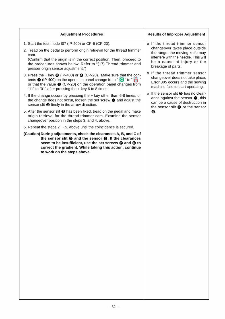
1. Start the test mode I07 (IP-400) or CP-6 (CP-20).
2. Tread on the pedal to perform origin retrieval for the thread trimmercam.(Confirm that the origin is in the correct position. Then, proceed tothe procedures shown below. Refer to “(17) Thread trimmer andpresser origin sensor adjustment.”)
3. Press the + key (IP-400) or (CP-20). Make sure that the con-tents (IP-400) on the operation panel change from “ “ to “ “or that the value (CP-20) on the operation panel changes from“11” to “01” after pressing the + key 6 to 8 times.
4. If the change occurs by pressing the + key other than 6-8 times, orthe change does not occur, loosen the set screw and adjust thesensor slit finely in the arrow direction.
5. After the sensor slit has been fixed, tread on the pedal and makeorigin retrieval for the thread trimmer cam. Examine the sensorchangeover position in the steps 3. and 4. above.
6. Repeat the steps 2. ~ 5. above until the coincidence is secured.
(Caution) During adjustments, check the clearances A, B, and C ofthe sensor slit and the sensor . If the clearancesseem to be insufficient, use the set screws and tocorrect the gradient. While taking this action, continueto work on the steps above.
– 32 –
Adjustment Procedures Results of Improper Adjustment
o If the thread trimmer sensorchangeover takes place outsidethe range, the moving knife mayinterfere with the needle. This willbe a cause of injury or thebreakage of parts.
o If the thread trimmer sensorchangeover does not take place,Error 305 occurs and the sewingmachine fails to start operating.
o If the sensor slit has no clear-ance against the sensor , thiscan be a cause of destruction inthe sensor slit or the sensor
.

(19) Adjustment of the moving knife and counter knife position
Counter knife position : The clearance between the counter knife and the needle hole guide is 1.0mm.Moving knife position : Before thread trimmer operation (standby state), the distance from the throat plate
front end to the tip of the thread cutter lever (small) is 18.5mm.However, there shall be a proper clearance toward the moving knife tip during needlethread clamp and feed forward.
– 33 –
(20) Floating amount of the thread tension disk
When the sewing machine power supply is turned off (AT solenoid is OFF), the gap between AT threadtension disk is 0.6 ~ 1mm.
Close contact
Standard Adjustment
Standard Adjustment
4 mm or less
AB
0.6 to 1mm
There shall be aclearance
18.5mm
18.5mm
1.0mm
1. Counter knife positionLoosen the counter knife set screw to adjust the position.
2. Moving knife positionLoosen the screw to adjust the position.
o If the clearance is less than1.0mm, thread may be cut by thecounter knife blade when thethread is pulled with the movingknife . In this case, upper andlower threads are cut into shortpieces.
o If the clearance is more than1.0mm, the residual thread lengthafter thread cutting operation be-comes longer beneath the work.
– 34 –
1. Turn off the power supply and look for any close contact between theAT solenoid and the thrust collar .
2. Loosen the three set screws and remove the thread tension cap.
3. Hold the tension releasing pin adjust collar not to let it rotate, andloosen the nut .
4. Turn the tension releasing pin adjust collar and adjust the gapbetween the thread tension disk . (Adjustment of thread tensiondisc floating)
5. Hold the tension releasing pin adjust collar and tighten the nut .Mount the thread tension cap by means of the set screw .
6. Turn on the power supply and set up the thread tension. Confirm thatthe thread tension disk are closed.
(Caution) When the tension releasing pin adjusting collar isrotated, the thread section should not be engaged withthe incomplete thread section of the thread tension re-leasing pin . (The thrusting distance of the thread ten-sion releasing pin should be 4 mm or less from thetension releasing pin adjusting collar .)* If the amount of disc floating cannot be adjusted prop-
erly under the condition that the thrusting distance is4 mm or less, loosen the set screw and adjust theAT link unit (front) in the right-left direction.Refer to “(22) AT unit connection/disconnection”.
o If the amount of disc floating is tooless, the residual thread lengthcan be changed or shortenedwhen the thread is thick.
o If the amount of disc floating is toomuch, the thread tension discs cannot close completely and nor-mal thread tension may fail to bechosen. This can be a cause ofimperfect sewing.
o If the thread section of the tensionreleasing pin adjusting collar is engaged with the incompletethread section of the thread ten-sion releasing pin , the threadtension releasing pin may bedamaged.
Adjustment Procedures Results of Improper Adjustment
Adjustment Procedures Results of Improper Adjustment

(21) Second thread tension connection / disconnection
1. Loosen the set screw .
2. Remove three setscrews and take out the thread tension cap .
3. Remove the nut and the tension releasing pin adjusting collar . Then take out the thread tension discpressing plate and three thread tension disc return springs .
4. Pull out the second thread tension to remove it. (Arrow A )
5. For reassembly, follow the steps of 4. to 1. above.
– 35 –
Procedures of disassembling
A

1. When mounting the second thread tension , confirm in advance that the pin block of the AT link unit(front) is exactly settling in the hole of the thread tension pressing pin . If you try to mount the secondthread tension forcedly with the pin area left disengaged, this may result in breakage in the thread tensionpressing pin or malfunction.
2. After the completion of mounting, make adjustments of (20) Floating amount of the thread tension disk and(39) Adjustment of thread take-up spring; 1) Stroke adjustments.
– 36 –
Procedures of assembling

(22) AT unit connection / disconnection
1. Remove the set screw of the AT link unit (front) and take out the second thread tension . ((21) Referto “Second thread tension connection / disconnection.”)
2. Draw out the cotter pin from the pin block (H type) or (S type) of the AT link unit (rear) . Be carefulnot to drop the washer at that time.
3. Lift the AT joint block of the AT unit upward to remove the block from the pin block (H type ) or (Stype) of the AT link unit (rear) .
4. Draw out the AT link unit (front) from the plane side (in the direction of the arrow E ) and remove it.
5. Remove the two set screws and take out the AT solenoid unit .
6. For reassembly, follow the steps of 5. to 1. above.
– 37 –
E
Procedures of disassembling
F
Close contact

1. For incorporating the AT solenoid unit into the system, run the solenoid cable from the rear of the ATsolenoid unit to the rear end of the machine arm.
2. The center-to-center distance between the AT joints of the AT connector rod is 299 mm for S type and301 mm for H type.When the AT joints are disassembled or assembled, make sure that the center-to-center distance iscorrect, and that the front and rear of the AT joints are parallel. Failure to observe this may cause ATmalfunction resulting in incorrect thread tension.(When the AT joint is turned 4 times, the feed move amount comes to attain 2mm.)
3. For the pin block of the AT link unit (rear) , use the pin block for H type and the pin block for S type.The wrong pin position may cause AT malfunction resulting in incorrect thread tension.
4. After completion of all assembly work, make sure that the thrust collar closely contacts with the AT sole-noid unit . If there is a clearance between them, loosen 2 set screws and move the AT solenoid unit to the rear (Arrow F ) and secure it again.* If the above-mentioned center-to-center distance is great between the AT joints , the clearance will be
opened wider.
– 38 –
Close contact
S type: 299mm, H type: 301mm
Secure parallelism between plane and plane.
Procedures of assembling

(23) Wiper adjustment
(Caution) The intermediate presser supplied as standard accessory is available up to 5 mmmaterial thickness.However, the intermediate presser can not be used for the 3 mm material thicknessor more since the wiper can not pass the space between the tip of needle and theintermediate presser.Turn OFF the wiper switch in case of 3 mm material thickness or more.
A
– 39 –
Throat plate top surfaceHeight ofIntermediatePresser
1mm
10mm15° to 20°
V letter
1. When lowering the intermediate presser at the stop position after thread trimming (needle height fromthe top surface of throat plate is 17.7 mm.) and pressing wiper link section A , adjust the clearancebetween the center of needle and the inside of V letter of the wiper to 10 mm.
2. Press wiper link section A on the way and when the wiper has come to the underside of needle, adjustthe clearance to 1 mm.
3. The opening angle of the top end of the wiper is 15° to 20°.
Center of needle
Standard Adjustment
Wiper shaft cap

1. Turn OFF the power after stopping the thread trimming, or turn ONthe threading switch and lower the intermediate presser .
(Caution) As for the height of needle when adjusting the wiper, set the height when the sewing machine stopped af-
ter trimming the thread actually.2. Push wiper link section A and move the top end of the wiper to
the under side of the needle.3. In the state of the above item 2. , loosen setscrew and adjust the
clearance between the wiper and the tip of the needle should be (1mm) and the opening angle should be (15° To 20°). Then tightensetscrew .
4. Push wiper link section A to the last and loosen setscrew .5. In the state of the above item 4. , adjust the longitudinal (10 mm) and
lateral positions of the wiper . Then tighten setscrew .
o If the clearance between the wiper and needle is too small, the
wiper comes in contact with theneedle due to uneven stopposition of the main shaft, causingneedle breakage.
o If the clearance between the wiperand needle is excessive,
the wiper comes in contact withthe intermediate presser andthe wiper will damage the inter-mediate presser . Also, the in-termediate presser can not goup.
o If a clearance of 10 mm betweenthe inside of V letter of the wiper
and the center of needle ismistakenly set, the wiper fails tospread the thread.
o Similarly, If the center of needledoes not align with the V letter ofthe wiper , the wiper fails tospread the thread.
o If the opening angle of the wiper is excessive, thread sweeping
failure will occur.
– 40 –
Adjustment Procedures Results of Improper Adjustment

(24) Adjusting the pre-load of the X-Y table
– 41 –
When removing the X-Y table assy from the sewing machine, re-adjustment of the pre-load is necessary forthe X axis only.
Standard Adjustment
9.8 to 39.2N
Bed
1. Hold down the X fixed race (rear) in the direction of the arrow totighten 4 set screws .
2. Loosen 4 set screws .3. Hold down the X fixed race (front) in the direction of the arrow to
tighten 4 set screws . * Then, adjust the retainer compensatingtorque between 9.8 to 39.2 N (1 to 4 kgf) on both right and left sides.
4. Tighten 4 set screws .* Retainer compensating torque: This is a load necessary to move the
race table after the retainer has come in contact with the Xstopper .This torque should be measured when the belt is slack before pulsemotor installation.
– 42 –
Adjustment Procedures Results of Improper Adjustment
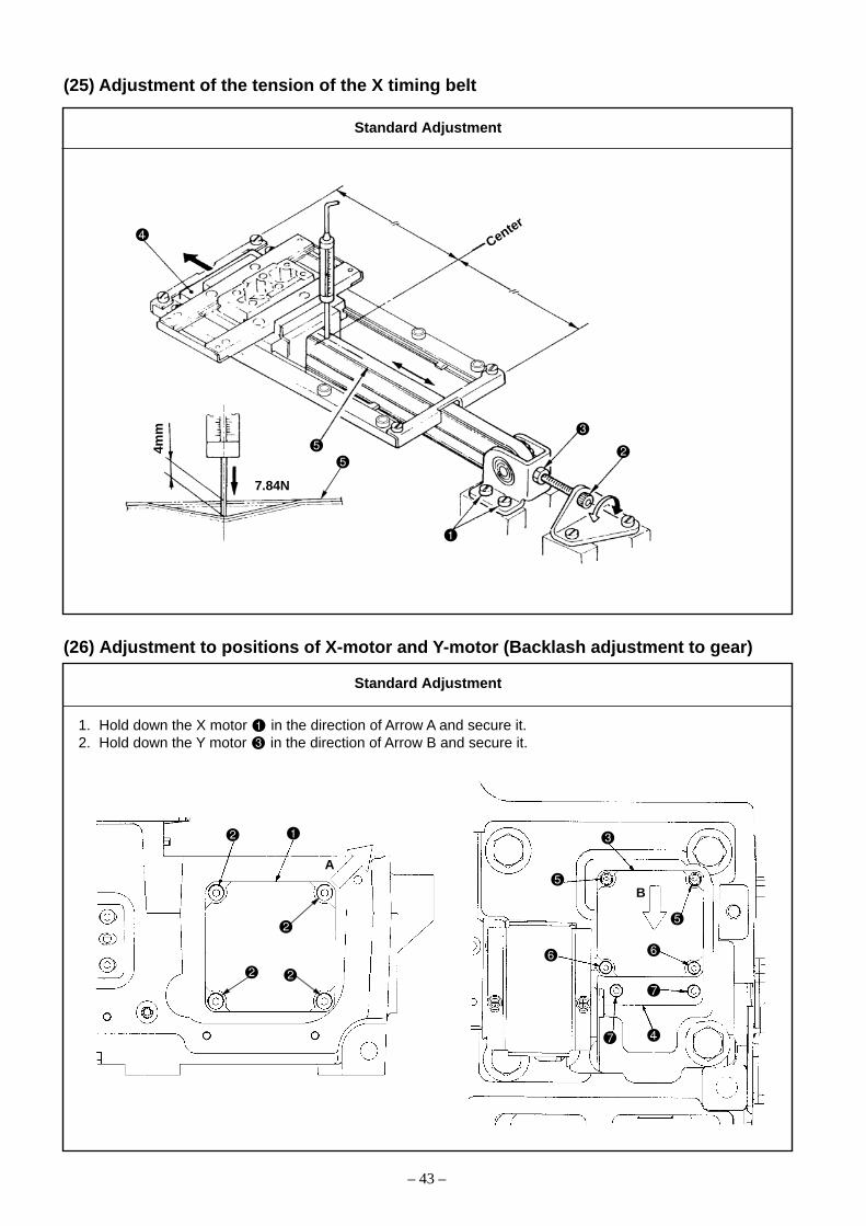
(25) Adjustment of the tension of the X timing belt
– 43 –
Center
7.84N
4mm
(26) Adjustment to positions of X-motor and Y-motor (Backlash adjustment to gear)
Standard Adjustment
Standard Adjustment
1. Hold down the X motor in the direction of Arrow A and secure it.2. Hold down the Y motor in the direction of Arrow B and secure it.
A
B

1. Move the race table to the left end (in the direction of the arrow).2. Tighten the adjusting screw and fix the nut so that the load
point makes a warp of 4mm when a load of 7.84N (800gf) measuredby a spring balance is applied to the timing belt .
3. Tighten the set screw and check the amount of deflection again.
– 44 –
1. Loosen 4 set screws securing the X motor .2. Hold down the X motor in the direction of Arrow A and tighten 4 set
screws to secure the X motor .3. Loosen 2 set screws , 2 set screws , all of which secure the Y
motor , and 2 set screws securing the Y motor mounting plate.
4. Hold down the Y motor in the direction of Arrow B and tighten 2 setscrews that are positioned upper. Then, tighten 2 set screws that are positioned lower and 2 set screws securing the Y motormounting plate .
o If the X motor or Y motor is helddown inadequately, feeding gearbacklash is increased and needlelocat ion accuracy may bereduced. In addition, feeding errormay be caused resulting in needlebreakage, and other problems.
o If the pushing is excessive, theload of the feed will become large,causing the failure of the feed.
Adjustment Procedures Results of Improper Adjustment
Adjustment Procedures Results of Improper Adjustment
o If the tension is excessive, it willcause timing belt breakage.
o If the tension is too low, it willcause failure of the feed.
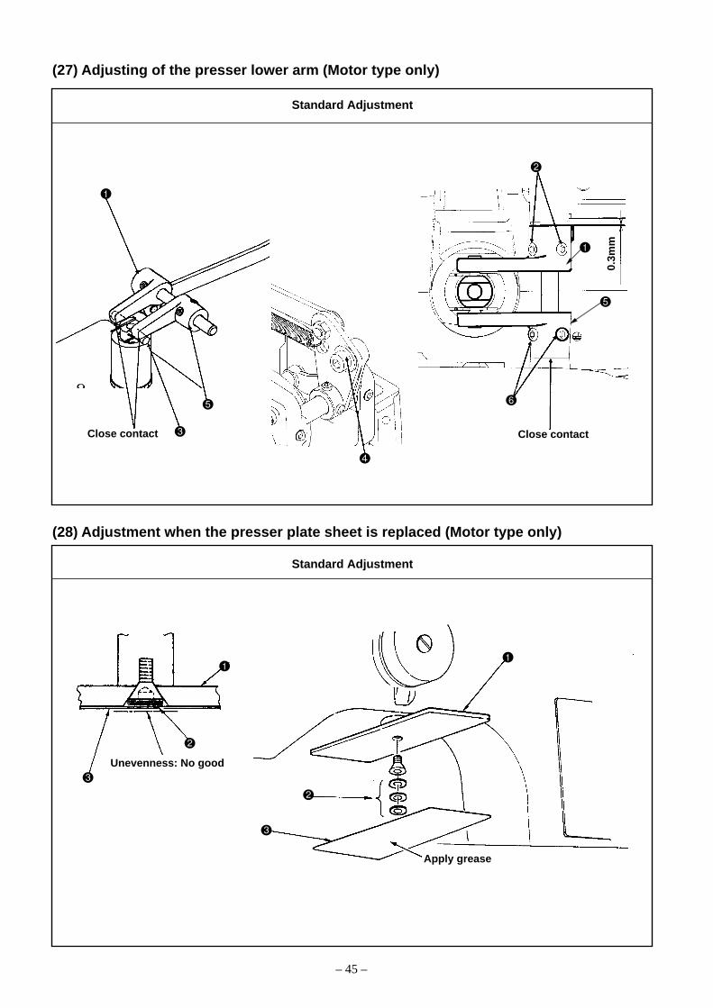
(27) Adjusting of the presser lower arm (Motor type only)
– 45 –
(28) Adjustment when the presser plate sheet is replaced (Motor type only)
Apply grease
Unevenness: No good
Standard Adjustment
Standard Adjustment
Close contact
0.3m
m
Close contact

1. Secure the presser lower arm A so that the clearance between theholding arm and machine arm becomes 0.3 mm with 2 set screws
.2. Use the adjusting screw to make sure that the presser lower arm
A closely contacts with the holding pin under the condition ofthe presser lifted.
3. Make the angle between the presser lower arm B and pressingpin the same as the angle between the presser lower arm A and pressing pin , and keep the machine arm to contact closelywith the presser lower arm B , and tighten the two set screws .
o If the angle of the presser lowerarm A and B is not equal, itwill cause loosening the arm asm.screws or the breakage.
o If the clearance is too small be-tween the presser lower arm A and the arm, this can be a causeof maloperation during pushingdown.
– 46 –
1. Put an appropriate number of the spacers into the presser plate to make the presser plate sheet even.
2. In regard to the application of grease, refer to “PRESSER PLATE &MANUAL PRESSER MECHANISM COMPONENTS” described in10.-(4) Parts to which grease•lock-tight is applied.
o The step difference will causemalfunction of the feed.
Adjustment Procedures Results of Improper Adjustment
Adjustment Procedures Results of Improper Adjustment

(29) Height of the slider and pasting of the presser plate sheet (Pneumatic type only)
– 47 –
1. Follow the dimensions in the drawing below for pasting the presser plate sheet on the presser plate .Apply grease after pasting the sheet.
2. Bring the upper end of the slider into close contact with the presser plate .
Rear side of the sewing machine
Standard Adjustment
2mm 2mm
21m
m2mm 2mm
14m
mRear side of the sewing machine
Presser heightadjusting screw
1306, 2206
1510, 2210

1. Remove 4 set screws to remove the presser plate , and replacethe old presser plate sheet with new one.
2. After mounting the presser plate , adjust the height of the slider with 4 set screws . To position the height, lightly press the slider
to the presser plate when the presser goes up.
o If the position where the presserplate sheet was pasted iswrong, abrasion of relatedcomponents or peeling of thepresser plate sheet may occurresulting in a feed error due todirect contact between the slider
and presser plate .o Wrong slider height may cause
a feed error.
– 48 –
Adjustment Procedures Results of Improper Adjustment

(30) Adjusting the speed of the work clamp feet (Pneumatic type only)
– 49 –
1. Adjust the knob 1 and the knob 2 of the speed controller mounted on the solenoid valve and makeadjustments as described below.• Presser lifting (tube label: 1-A, 2-A) and presser lowering (tube label: 1-B, 2-B).• Loosen the knob 2 and turn the knob 1 once fully to the right in order to make 3 turns to the left.
Since then, tighten the knob 2 .
Standard Adjustment

1. Adjust the speed referring to Standard Adjustment.2. To increase the speed of lowering/raising the work clamp foot, turn
the knob 1 counterclockwise.3. To decrease the speed, turn the knob 1 clockwise.
o When the work clamp foot comesdown, the noise is big.
o The work clamp foot fails to rise.
– 50 –
Adjustment Procedures Results of Improper Adjustment

(31) Making the origin setting gauge
(32) Adjusting the X origin sensor
When the feed is in the mechanical origin, align the tip of the needle with the lateral position of the engraved dotof the origin.
Hole ø4 forpositioning pin
Tap M4 for setscrew
16 mm
36 mm
43.5
mm
63.5
mm
A
B
D
C
– 51 –
Standard Adjustment
Standard Adjustment
87.5
mm
107.
5 m
m
Origin marking for 1316 , 2206
Origin marking for 1510 , 2210

1. Make an origin setting gauge as shown in the figure, and attach itto the work clamp foot .
1. Start the test mode I06 (IP-400), or CP-2 (CP-20).2. When the star pedal is depressed, the feed moves to the mechanical
origin and stops.3. Lower the needle and check the right and left displacement based on
the engraved marking of the origin.4. When the engraved marking of the origin is found to be displaced in
Direction A from the needle tip, loosen the two set screws andadjust the sensor mounting plate in Direction C. After adjustments,tighten the two set screws .
5. When the engraved marking of the origin is found to be displaced inDirection B from the needle tip, loosen the two set screws andadjust the sensor mounting plate in Direction D. After adjustments,tighten the two set screws .
(Caution) After the adjustment, make sure that the slit plate doesnot interfere with the sensor .
– 52 –
Adjustment Procedures Results of Improper Adjustment
Adjustment Procedures Results of Improper Adjustment

(33) Adjusting the Y origin sensor
When the feed is in the mechanical origin, align the tip of the needle with the longitudinal position of theengraved dot of the origin.
– 53 –
Standard Adjustment
A
B Main motor side (rear)
Operator side (front)
C
D

1. Start the test mode I06 (IP-400) or CP-2 (CP-20).2. When the pedal is trodden on, the feed moves to the mechanical
origin and then stops.3. Lower the needle and check the front-rear displacement from the
engraved marking of the origin.4. When the engraved marking of the origin is found to be displaced in
Direction A from the needle tip, adjust the sensor mounting plate in Direction C. (Loosen the set screws and fix the set screws after adjustments.)
5. When the engraved marking of the origin is found to be displaced inDirection B from the needle tip, adjust the sensor mounting plate in Direction D. (Loosen the set screws and fix the set screws after adjustments.)
– 54 –
Adjustment Procedures Results of Improper Adjustment
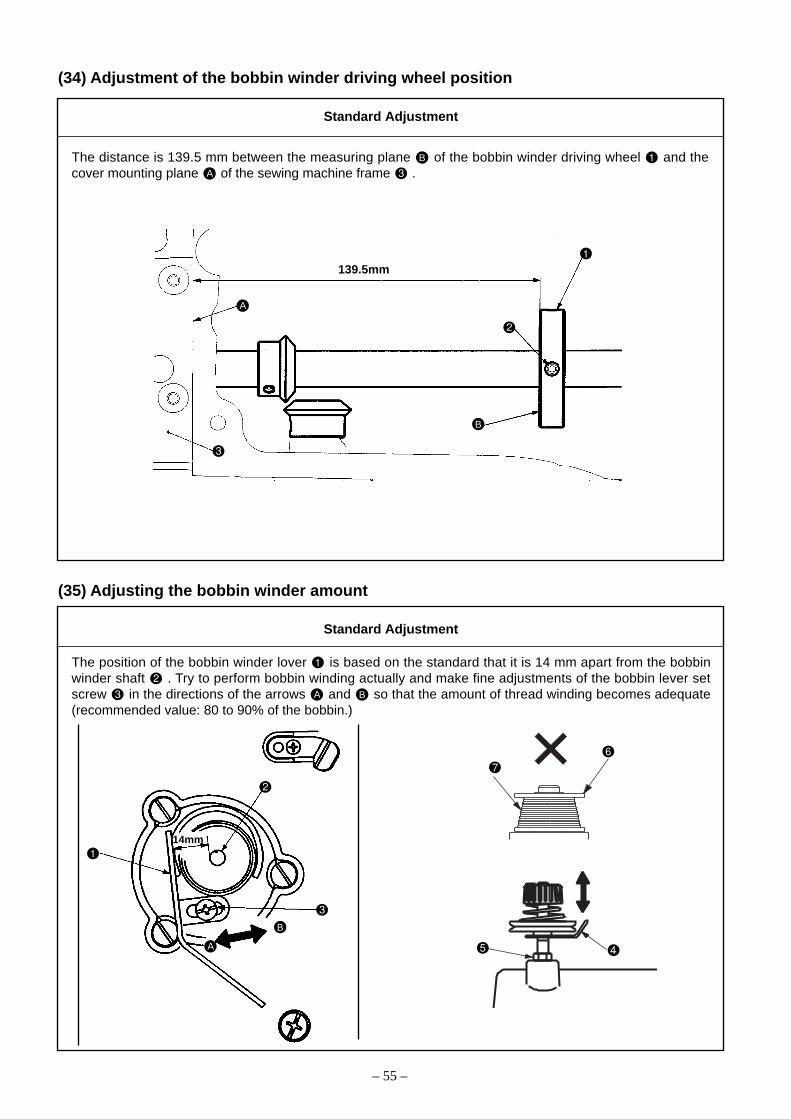
(34) Adjustment of the bobbin winder driving wheel position
The distance is 139.5 mm between the measuring plane B of the bobbin winder driving wheel and thecover mounting plane A of the sewing machine frame .
(35) Adjusting the bobbin winder amount
The position of the bobbin winder lover is based on the standard that it is 14 mm apart from the bobbinwinder shaft . Try to perform bobbin winding actually and make fine adjustments of the bobbin lever setscrew in the directions of the arrows A and B so that the amount of thread winding becomes adequate(recommended value: 80 to 90% of the bobbin.)
– 55 –
Standard Adjustment
Standard Adjustment
B
A
14mm
B
A
139.5mm

1. Loosen the two set screws to adjust the position (139.5mm) of thebobbin winder driving wheel and fix it with the two set screws .
o If the distance of 139.5mm isinsufficient, rubber ring wear mayoccur in the bobbin winder unit.In addition, the bearing life maybe reduced in the bobbin winderunit.
o If the distance of 139.5mm is ex-cessive, normal thread windingmay fail. In addition, this will alsocause rubber ring slippage in thebobbin winder unit and give riseto wear.
1. Loosen the set screw of the bobbin winder lever and adjust thedistance to 14mm between the bobbin winder lever and the bob-bin winder shaft . After that, tighten the set screw of the bobbinwinder lever.
2. Start the sewing machine and wind the thread at the bobbin winder.Confirm the amount of winding.1) If the amount of winding seems to be too much, adjust the bobbin
winder lever in the direction of the arrow B .2) If the amount of winding seems to be too less, adjust the bobbin
winder lever in the direction of the arrow A .
3. If the winding state of the thread around the bobbin winder seems to be uneven, loosen the nut and adjust the height of thethread tension control .(Example) If the amount of the wound thread is less on the upper
side of the bobbin winder as illustrated, adjust thethread tension control upwards.
o If too much thread is wound(thread protruded from the bobbinwinder ), the thread willcome in contact with the inside ofthe bobbin case and this can bea cause of sewing deficiency.
o If the amount of thread winding isuneven at top and bottom of thebobbin winder , stitch perfora-tion may become irregular.
– 56 –
Adjustment Procedures Results of Improper Adjustment
Adjustment Procedures Results of Improper Adjustment

(36) Adjustment of the shuttle upper spring and lower thread holder position
1. Shuttle upper spring : In regard to the right and left positioning, secure coincidence between thecenter of the needle and that of the groove width C. For the front-rearpositioning, join the needle rear end and the corner A block.
2. Lower thread holder : The amount of overlapping with the shuttle upper spring should be ad-justed so that the thread of Vinylon #8 can pass smoothly when it is pulledin the direction of the arrow E. After the best positioning has been se-cured, fasten the two set screws .
(Caution) If Part BBBBB and FFFFF is damaged, this is the cause of thread breakage, hangnail of thread, stainon thread, etc. Therefore, this part should be polished by the use of a buff or the like. Inparticular, the rear side should be handled with care.
(37) Shuttle felt
• Two pieces of the shuttle felt are inserted in the holes of the shuttle race . Confirm that the shuttle felts are not overloaded when the inner hook is set and turned along the shuttle race .
• Shuttle packing has been inserted in the hole of the shuttle race .
– 57 –
Standard Adjustment
Standard Adjustment
A
B
F
E
C
D
Shuttle

1. Remove the work feed bar, feed plate, and the throat plate. Adjustthe positioning of shuttle upper spring with the set screws (2pcs.).
2. Using the set screw , adjust the amount of overlapping D for the
lower thread holder and the shuttle upper spring .
(Caution) The right and left positions can also change during (15)hook adjustments. Position adjustment for the shuttleupper spring should be done after the completion ofstandard hook adjustment, without fail.
o If there is a front and reardisplacement or a right and leftdisplacement, needle threadbiting may occur into the hook.Too much motion to the rear sidewill cause the moving knife to failto hook the needle thread.
o Too much motion to the rear sidewill cause the moving knife to failto hook the needle thread.
o Too much motion to the left sidewill cause the moving knife to failto hook the bobbin thread.
1. If the shuttle felt seems to be protruded or it has been replacedwith a new one, push it in by means of tweezers or the like.
(Caution) Do not push it in excessively. Align the height and theplane of the shuttle race .
2. Confirm that the shuttle packing has been mounted assuredly.
o If the shuttle felt is protruded,this will be turned into a rotary loadof the inner hook, causing asewing error.
o If the shuttle felt is missing orpushed in too much, this will re-sult in hook lubrication deficiency,causing hook overheating andwear.
o If the shuttle packing has beenmissing, the shuttle felt andothers may be lost, and this canbe a cause of shuttle heating andwear.
– 58 –
Adjustment Procedures Results of Improper Adjustment
Adjustment Procedures Results of Improper Adjustment

(38) Shape of the shuttle race ring
If wear seems to be too much around the pointed tip of the inner hook, release the shuttle race ring andconfirm that the dimensions of the hatched area on the rear side are 0.3 x 8mm.
(39) Adjustment of thread take-up spring
8mm
Dim
ensi
on
A
0.3m
m
Stroke : The movable distance of the needle thread when the needle thread is pulled in the direction A untilthe thread take-up spring stops. 12 to 15 mm for S type, 12 to 18 mm for H type.
Tension : Adjust the thread take-up spring tension in accordance with the thread tension. (Actually sew amaterial and adjust the thread take-up spring tension to an appropriate value.)
– 59 –
Standard Adjustment
Standard Adjustment
A
B
When thread knotsare made.
12 t
o 1
5mm
C
Increase
Decrease

1. If the dimensions of 0.3 x 8mm are not secured, retouching is re-quired with the aid of an oil stone.
1) Stroke adjustmentLoosen the set screw , and turn the thread tension assembly .Turning it clockwise increases the movable distance and thread draw-ing amount.
2) Adjustment of thread take-up spring tensionTurn the thread tension post using a thin driver with the set screw
tightened to adjust the thread take-up spring tension. Turningit clockwise increases the thread take-up spring tension, and turnit counterclockwise decreases the tension.
(Caution) Set the stroke of the thread take-up spring shorterfor thin threads with thread number #50 or higher.
o If the stroke of the thread take-upspring is larger than the specifiedvalue:Length of remaining needlethread is shortened, causing theneedle thread to slip off the needleat the sewing start.
o If the stroke of the thread take-upspring is smaller than the speci-fied value:Needle thread breakage will oc-cur at the time of thread trimmingwhen using a thin thread.
(Caution)If the thread take-up spring interferes with the L-shapedthread guide , the thread take-up spring may fail to return tothe initial position before threadtrimming, and the length of re-maining needle thread may beshort. If such a trouble occurs,bend the section CCCCC of the threadtake-up spring to widen theclearance BBBBB .
– 60 –
Adjustment Procedures Results of Improper Adjustment
Adjustment Procedures Results of Improper Adjustment
Part No. Name of part Remarks
0.8 14103253 Shuttle race ring A Optional
1.3 14103352 Shuttle race ring B Standard
1.7 14103659 Shuttle race ring C Optional
1.9 B1817210DAD Shuttle race ring D Optional
Dimension A(mm)

(40) Needle thread clamp device connection/disconnection
1. Remove the hinge screw .* If the hinge screw cannot be seen from the open part of the needle thread clamp device , try to
move the needle thread clamp connector link by hand in the direction of A or B.
2. Remove the four set screws of the needle thread clamp base and take out the needle thread clampdevice .
Open part
AB
– 61 –
Procedures of disassembling

1. Push the needle thread clamp device in the direction of A and fix it with the four set screws . Tighten thehinge screw .
2. Turn on the power supply and press the key twice so that the needle thread clamp support platecomplete is positioned at the far advanced end.Confirm that the distance between the needle thread clamp support plate complete and the needle is3.3 to 3.7mm and 1.7 to 2.3mm, respectively.
3. If the distance seems to be inadequate, loosen the four set screws and move the needle thread clampdevice for adjustment.
(Caution) For the prevention of injury, the distance should be checked only if the sewing LED is unlit.(Press the key twice after the power supply has been turned on.)
4. After the completion of the above-mentioned reassembly, make adjustments according to “(41) Adjusting theneedle thread clamp sensor.”
1.7
to 2
.3m
m
3.3 to 3.7mm
– 62 –
Procedures of assembling

(41) Adjusting the needle thread clamp sensor
When the needle thread clamp support plate complete is withdrawn by 3 to 4 pulses from the needle threadclamp position (Caution 1., 2.) the clearance A toward the needle thread clamp becomes 0.
(Caution) 1. The needle thread clamp position is known as the position returned by one step from themost advanced position when the key is pressed after the origin retrieval by the TestMode I08 (IP-400) or CP-7 (CP-20).
2. According to the thread clamp specifications, the memory switch U69 may change.S Type →→→→→ 0H Type → → → → → 1
– 63 –
Standard Adjustment
C B
A
3 to 4mm
1.7
to 2
.3m
m

In the first place, confirm that the setting value of the memory switchU69 is [0] for S Type and [1] for H Type. Since then, make theadjustments as specified below.
1. Start the Test Mode I08 (IP-400) or CP-7 (CP-20).
2. Tread on the pedal for needle thread clamp origin retrieval.
3. Press the key twice and set the needle thread clamp supportplate complete in the needle thread clamp position.
4. Confirm that the clearance A becomes 0 between the needle threadclamp and the needle thread clamp support plate complete when the [–] key is pressed 3 to 4 times (for 3 to 4 pulses), and thatboth the needle thread clamp and the needle thread clamp sup-port plate complete move together when the [–] key is pressedagain.
5. If the clearance A becomes 0 with 5 or more pulses, loosen the setscrew and fix the sensor mounting plate after moving it in thedirection B.If the clearance A becomes 0 with less than 3 pulses, loosen the setscrew and fix the sensor mounting plate after moving it in thedirection C.After the sensor mounting plate has been fixed, check the above-mentioned steps 2. to 4.
6. Using 3 to 4 pulses, repeat the steps 2. to 5. above until the clear-ance A becomes 0.
7. Tread on the pedal for needle thread clamp origin retrieval anddefine the most advanced position by pressing the key once.
8. Confirm that the distances between the needle thread clamp supportplate complete and the needle are kept at 3 to 4mm and 1.7 to2.3mm, respectively.
9. If the distance is found to be inadequate, adjust the position towardthe needle according to (40) Needle thread clamp device connec-tion/disconnection. Since then, make the above-mentioned sensoradjustments again.
o If there are too many pulses useduntil the clearance A becomes 0,this can be a cause of unthreadingat the beginning of sewing.
o If the number of pulses is too smalluntil the clearance A becomes 0,the resistance toward the needlethread becomes large and thiscan be a cause of thread break-age at the beginning of sewing.
o If the distance is improper be-tween the needle thread clampsupport plate complete and theneedle , this will give rise to in-terference between the needlethread clamp and the needle
.
– 64 –
Adjustment Procedures Results of Improper Adjustment

(42) Adjusting the needle thread clamp notch
1. Needle thread clamp notch R position
• When the needle thread clamp link complete is pressed in Direction A, and Part B of the needle threadclamp support plate complete and the needle thread clamp begins to open, the distance betweenthe needle thread clamp and the needle thread clamp base becomes 21mm for S Type and 16.5mmfor H type.
– 65 –
Standard Adjustment
2. Needle thread clamp notch F position• When the needle thread clamp link complete is pressed in Direction C, and Part B of the needle thread
clamp support plate complete and the needle thread clamp begins to open, the distance betweenthe needle thread clamp and the needle thread clamp base becomes 23mm for S Type and 21mmfor H Type.
A
B
D
Contact
21mm
C
B E
Contact
23mm
A
B
D
Contact
16.5mm
C
B E
Contact
21mm
S Type H Type
S Type H Type

1. Needle thread clamp notch R adjustment
1) Loosen the two set screws .2) Press the needle thread clamp link complete in Direction A so that
the distance between the needle thread clamp and the needlethread clamp base becomes 21mm for S Type and 16.5mm for HType.Move the needle thread clamp notch R (S Type) or the needlethread clamp notch RH (H Type) in Direction D, lightly press ittoward the needle thread clamp cam plate , and tighten the twosetscrews .
2. Needle thread clamp notch F adjustment
1) Loosen the two set screws .2) Press the needle thread clamp link complete in Direction C so that
the distance between the needle thread clamp and the needlethread clamp base becomes 23mm for S Type and 21mm for HType. Move the needle thread clamp notch F (S Type) or theneedle thread clamp notch FH (H Type) in Direction E, lightly pressit toward the needle thread clamp cam plate , and tighten the twosetscrews .
o If the distance is too long betweenthe needle thread clamp andthe needle thread clamp base ,the needle thread release timingbecomes earlier and this can bea cause of unthreading at thebeginning of sewing.
o If the distance is too short be-tween the needle thread clamp and the needle thread clamp base
, the needle thread release tim-ing is delayed and this can be acause of needle thread end re-maining on the rear side of thematerial.
o If the distance is too long betweenthe needle thread clamp andthe needle thread clamp base ,the needle thread release timingbecomes earlier and this can bea cause of needle thread end re-maining on the rear side of thematerial or jamming of needlethread into the needle threadclamp .
o If the distance is too short be-tween the needle thread clamp and the needle thread clamp base
, the needle thread clamp tim-ing is delayed and this can be acause of failure in needle threadclamping.
o Adjustments should conform tothe adjustment values accordingto the needle thread clamp speci-fications (S Type or H Type). Oth-erwise, this can be a cause of fail-ure in needle thread clamping op-eration.
– 66 –
Adjustment Procedures Results of Improper Adjustment

– 67 –
(1) Start and change
To change the memory switch (level 2):The sewing machine operation can be changed bychanging the setting of the memory switch.
1. For IP-400:(1) To call up the screen showing the memory switch
data (level 2) list:Hold down the switch for approx. 6 seconds,and the page change button (A) appears at thetop of the screen. Press the page change button tocall up the next page, and the memory switch (level2) button (B) appears. Press the memory switch(level 2) button to call up the screen that shows thelist of memory switch data (level 2).
(2) To select the memory switch button to bechanged:Select the data item (D) to be changed using the upand down scroll buttons (C).
(3) To change memory switch data (level 2):Memory switch data (level 2) has 2 types of dataitems: one is where a value is changed, and the otheris where a pictograph is selected. The data itemswhere a value is changed are colored pink and num-bered such as and the value can be changedwith + and – buttons shown on the screen. Thedata items where a pictograph is selected are col-ored blue and numbered such as and picto-graphs shown on the screen where data items arechanged are selectable.Refer to “4.-(2) Function list” for further informationabout memory switch data (level 2).
A
B
D C
4. Memory switch

– 68 –
2. For CP-20:1. Press the key when the sewing LED is off to
activate the user setting mode (Level 1)of the memoryswitch.Hold down the key for 6 seconds to activate theservice setting mode (Level 2) of the memory switch.(Caution) A 3-second and a 6-second buzzers
sound when the key is held down. The3-second buzzer informs users of ac-tivation of the test mode.
2. Change the memory switch number with the and keys.
3. Press the key when the memory switch numberto be changed appears. On this occasion, the sew-ing LED is turned on.
4. Change the contents of the memory switch with the and keys.
5. The factory settings can be restored with the key.
6. Press the key to register the changes. Thesewing LED is turned off and the screen returns tothe one where the memory switch number is selected.
7. Press the key to end the memory switch settingmode and to return to the regular mode.
Upper 3 figures indicate amemory switch number.
Lower 2 figures indicatesetting contents.

– 69 –
(2) Function listLevel 1 (Refer to the instruction manual for changing procedure.)
No. Item Setting range
Initial value
SS/HS SL/HL SL/HL SL/HL SL/HL1306 1306 1510 2206 2210
SS/HS1306FU05
SL/HL1306FU05
SL/HL1510FU05
SL/HL2206FU05
SL/HL2210FU05
1 Maximum sewing speed 200 to 2700rpm 100rpm 2700
2 Sewing speed of 1st stitch 200 to 1500rpm 100rpm 1500In case of with thread clamp
3 Sewing speed of 2nd stitch 200 to 2700rpm 100rpm 2700In case of with thread clamp
4 Sewing speed of 3rd stitch 200 to 2700rpm 100rpm 2700In case of with thread clamp
5 Sewing speed of 4th stitch 200 to 2700rpm 100rpm 2700In case of with thread clamp
6 Sewing speed of 5th stitch 200 to 2700rpm 100rpm 2700In case of with thread clamp
7 Thread tension of 1st stitch 0 to 200 1 200In case of with thread clamp
8 Thread tension setting at the time 0 to 200 1 0of thread trimming
9 Thread tension changeover timing –6 to 4 1 (4°) 0at the time of thread trimming
10 Sewing speed of 1st stitch 200 to 1500rpm 100rpm 200In case of without thread clamp
11 Sewing speed of 2nd stitch 200 to 2700rpm 100rpm 600In case of without thread clamp
12 Sewing speed of 3rd stitch 200 to 2700rpm 100rpm 1000In case of without thread clamp
13 Sewing speed of 4th stitch 200 too2700rpm 100rpm 1500In case of without thread clamp
14 Sewing speed of 5th stitch 200 to 2700rpm 100rpm 2000In case of without thread clamp
Smallestchange-able unit

– 70 –
No. Item Setting range
Initial value
SS/HS SL/HL SL/HL SL/HL SL/HL1306 1306 1510 2206 2210
15 Thread tension of 1st stitch 0 to 200 1 0In case of without thread clamp
16 Thread tension changeover timing –5 to 2 1 –5at the sewing startIn case of without thread clamp
0: Normal
17 Operation panel key lock mode 1: X enlarging/ – 0(CP-20 only) Y enlarging/speed-
Item skip
0: Sewing up18 Counter motion selection counter – 0
(CP-20 only) 1: Bobbin threadDown counter
19 Height of presser at the time of 50 to 90 1 702-step stroke
0: Without buzzersound
20 Buzzer sound can be prohibited 1: Panel operating – 2sound
2: Panel operatingsound + error
21 Number of stitches of thread clamp 1 to 7 (stitches) 1 2release is set
22 Clamping timing of thread clamp can –10 to 0 1 (4°) 0be delayed
23 Thread clamp control can be 0: Normalprohibited – 0
1: Prohibition
Smallestchange-able unit
SS/HS1306FU05
SL/HL1306FU05
SL/HL1510FU05
SL/HL2206FU05
SL/HL2210FU05

– 71 –
No. Item Setting range
Initial value
SS/HS SL/HL SL/HL SL/HL SL/HL1306 1306 1510 2206 2210
24 Feed motion timing is selected -8 to 16 (4o in steps 1 (4°) 3Set the timing in “–” direction when of, 140 to 44°)stitch is not well-tightened.
0: Presser goes upafter moving at startof sewing
25 State of the presser after end of 1: Presser goes up – 0sewing is selected immediately afterend
of sewing
2: Presser goes up bypedal operation aftermoving at start of sewing
26 Presser lifting motion at the end 0: With presser upof sewing can be set – 0
1: Wuthout presser up
27 Origin retrieval can be performed 0: Without originevery time after end of sewing retrieval – 0(other than cycle sewing)
1: With origin retrieval
28 Origin retrieval in cycle sewing can 0: Without originbe set retrieval
1: Every time 1 – 0pattern is finished
2: Every time 1cycle is finished
29 Start of presser when sewingmachine stops by temporary stop 0: Presser rise – 0command can be selected
1: Presser rise withpresser switch
Smallestchange-able unit
SS/HS1306FU05
SL/HL1306FU05
SL/HL1510FU05
SL/HL2206FU05
SL/HL2210FU05

– 72 –
No. Item Setting range
Initial value
SS/HS SL/HL SL/HL SL/HL SL/HL1306 1306 1510 2206 2210
0: Up position
30 Needle stop position is set – 01: Upper deadpoint
31 Thread trimming can be prohibited 0: Normal – 0
1: Thread trimmingprohibited
32 Route of return to origin by return to 0: Disabled – 0 1origin button can be selected
1: Pattern datareverse tracing
2: Origin retrieval →sewing start position
33 Bobbin winding speed can be set 800 to 2000rpm 100rpm 1600
34 Motion method of wiper can be 0: Disabledselected – 1
1: Enabled
35 Unit of sewing shape size change 0: % input – 0can be selectedFunction for IP-400 only
36 Thread tension output time when 0 to 20 (1sec) 1sec 0needle thread tension setting can (0: No threadbe set tension output)
37 Bend position of thread clamp is 0: S type 1 S type: 0/H type: 1selected 1: H type thin thread
(#50 to #8)2: H type intermediate3: H type thick threas(#5 to #2)
Smallestchange-able unit
SS/HS1306FU05
SL/HL1306FU05
SL/HL1510FU05
SL/HL2206FU05
SL/HL2210FU05
1: Actual size input

– 73 –
No. Item Setting range
Initial value
SS/HS SL/HL SL/HL SL/HL SL/HL1306 1306 1510 2206 2210
Thread clamp and thread clamp 0: Standard (front)38 position selection – 0
1: Rear
0: Disabled
39 Thread breakage detection selection – 1
1: Enabled
40 Number of invalid stitches at the start 0 to 15 stitches 1 8of sewing of thread breakage detection
41 Number of invalid stitches during 0 to 15stitches 1 3sewing of thread breakage detection
(For motor-driven frame)0: 1 step1: 2-step stroke(move downward to theowest point with presser SW)2: 2-step stroke(start to move down-ward to the lowestpoint with start SW)3: 2-step stroke (Withpresser SW1: mid-point,lowermost position, rise)4-99: 1 step(For pneumatic frame)0: Integrated type frame
42 Feeding frame control/pedal 1: Right-left separate 1 0 1 0 2open-close type frame, no preference
between right and left2: Right-left separatetype frame, order: right → left3: Right-left separatetype frame, order: left → right4: Integrated type stroke5: Right-left separatetype left stroke, no preferencebetween right and left6: Right-left separatetype left stroke,order: right → left7: Right-left separatetype left stroke,order: left → right8-99: Integratedtype frame
Smallestchange-able unit
SS/HS1306FU05
SL/HL1306FU05
SL/HL1510FU05
SL/HL2206FU05
SL/HL2210FU05

– 74 –
No. Item Setting range
Initial value
SS/HS SL/HL SL/HL SL/HL SL/HL1306 1306 1510 2206 2210
(For motor-driven frame)0: 1 step1: 2-step stroke(move downwardto the lowest pointwith presser SW)2: 2-step stroke(start to move down-ward to the lowestpoint with start SW)3-99: 1 step(For pneumatic frame)0: Integrated type frame1: Right-left separate typeframe, no preferencebetween right and left
43 Feeding frame control: 2: Right-left separate 1 0 1 0 2midway stop time open/close type frame, order: right →left
3: Right-left separatetype frame, order: left → right4: Integrated typeframe stroke5: Right-left separatetype left stroke, nopreference betweenright and left6: Right-left separatetype left stroke, order: right → left7: Right-left separatetype left stroke,order: left → right8-99: Integrated type frame
0: Without44 Pedal SW 1 with/without latch – 1
1: With
0: Without45 Pedal SW 2 with/without latch – 1
1: With
0: Without46 Pedal SW 3 with/without latch – 1
1: With
Smallestchange-able unit
SS/HS1306FU05
SL/HL1306FU05
SL/HL1510FU05
SL/HL2206FU05
SL/HL2210FU05
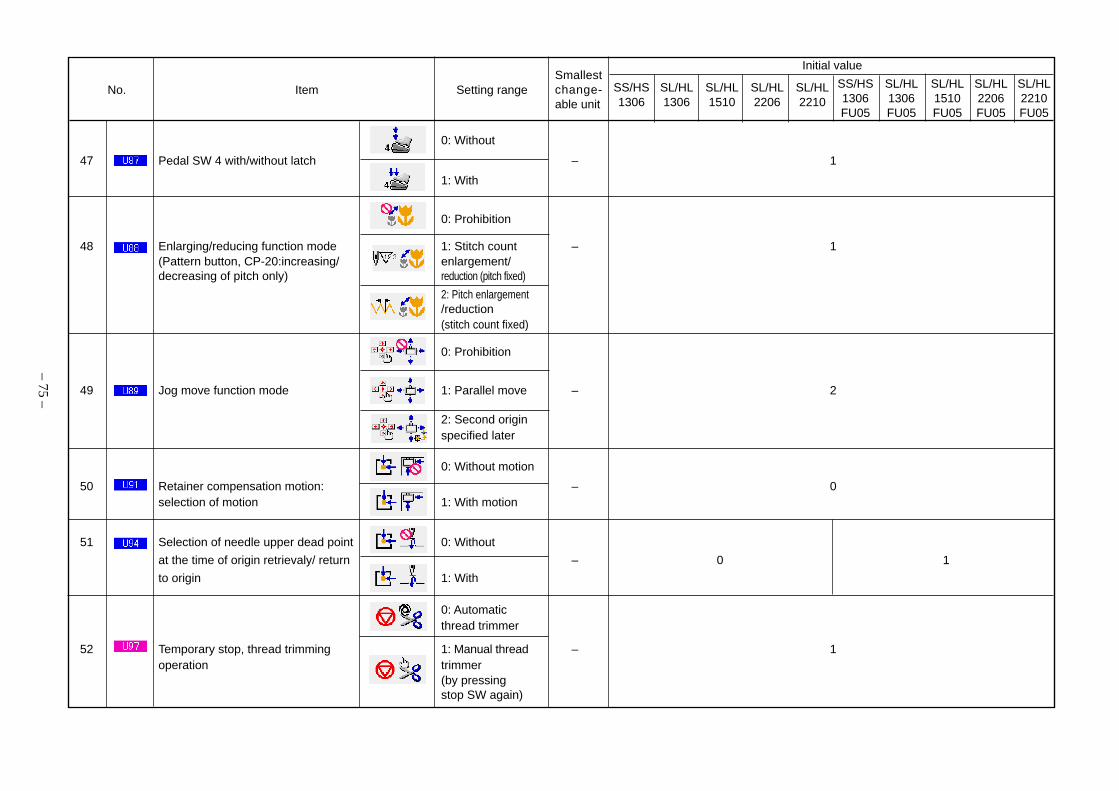
– 75 –
No. Item Setting range
Initial value
SS/HS SL/HL SL/HL SL/HL SL/HL1306 1306 1510 2206 2210
0: Without
47 Pedal SW 4 with/without latch – 1
1: With
0: Prohibition
48 Enlarging/reducing function mode 1: Stitch count – 1(Pattern button, CP-20:increasing/ enlargement/decreasing of pitch only) reduction (pitch fixed)
2: Pitch enlargement/reduction(stitch count fixed)
0: Prohibition
49 Jog move function mode 1: Parallel move – 2
2: Second originspecified later
0: Without motion
50 Retainer compensation motion: – 0selection of motion 1: With motion
51 Selection of needle upper dead point 0: Without
at the time of origin retrievaly/ return – 0 1
to origin 1: With
0: Automaticthread trimmer
52 Temporary stop, thread trimming 1: Manual thread – 1operation trimmer
(by pressingstop SW again)
Smallestchange-able unit
SS/HS1306FU05
SL/HL1306FU05
SL/HL1510FU05
SL/HL2206FU05
SL/HL2210FU05

– 76 –
No. Item Setting range
Initial value
SS/HS SL/HL SL/HL SL/HL SL/HL1306 1306 1510 2206 2210
0: 2700rpm/3.0mm
53 Main motor X/Y feed synchronized
control, speed/pitch 1: 2200rpm/3.0mm – 0
2: 1800rpm/3.0mm
3: 1400rpm/3.0mm
0: Disabled(lowering fixed)
54 Intermediate presser with/without 1: Enabled – 1control (lowering with sewing
data during operation)
2: Enabled(lowering during feedingfront and feeding back)
0: Immediatelybefore sewing
55 Intermediate presser lowering machine headtiming activation – 0
1: Synchronizationwith last feeding frame
0: Above intermediate56 Intermedia presser : wiper sweeping presser
position 1: Above intermediate – 0 (side-sweeping wiper wearing) presser (intermediate
presser lowest position)
2: Below intermediatepresser
0: without
57 With/without air pressure detection – 0 1
1: with
Smallestchange-able unit
SS/HS1306FU05
SL/HL1306FU05
SL/HL1510FU05
SL/HL2206FU05
SL/HL2210FU05

– 77 –
No. Item Setting range
Initial value
SS/HS SL/HL SL/HL SL/HL SL/HL1306 1306 1510 2206 2210
58 Intermediate presser down position 0 to 7.0mm 0.1 3.5settingRefer to Instruction Manual,“I-4-7. Intermediate presser height”.
0: Without
59 With/without needle cooler control – 1
1: With
60 Greas-up error Counted by 1 stitchClearing of number of stitches of Only “clear” is – –
grease-up is performed available.
1: Japanese
61 Language selection 2: English 1 1
3: Chinese
Smallestchange-able unit
SS/HS1306FU05
SL/HL1306FU05
SL/HL1510FU05
SL/HL2206FU05
SL/HL2210FU05

– 78 –
No. Item Setting range
Initial value
SS/HS SL/HL SL/HL SL/HL SL/HL1306 1306 1510 2206 2210
1 Motor presser presser lowering drive speed 100 to 1500pps 10pps 1500
2 Motor presser presser rising drive speed 100 to 3000pps 10pps 3000
3 Thread trimming drive speed (+ presser rising) 100 to 1500pps 10pps 1000
0: Ineffective
1: Effective – 1
4 Temporary stop input selection 2: Thread trimmingwith temporary stopswitch or start withstart pedal aftertemporary stop
0: 400rpm
5 Thread trimming speed – 1
1: 800rpm
0: Ineffective
6 Selection of thread trimming jump – 1
feed control 1: Effective
7 Needle hole guide diameter at 1.6 to 4.0mm 0.2mm S tyoe: 1.6/H type: 2.0controlling thread trimming jump feed
Thread trimmer control prohibition 0: Normal operation
8 selection – 0
1: Prohibited to use
9 Output time of magnet wiper on 10 to 500ms 10ms 50
10 Delayed time of magnet wiper off 10 to 500ms 10ms 80
• Level 2
Smallestchange-able unit
SS/HS1306FU05
SL/HL1306FU05
SL/HL1510FU05
SL/HL2206FU05
SL/HL2210FU05

– 79 –
No. Item Setting range
Initial value
SS/HS SL/HL SL/HL SL/HL SL/HL1306 1306 1510 2206 2210
11 Wiper output timing select at upper 0: Up position
dead point stop – 0
1: Upper dead point
12 Moving limit range in +X direction 0 to 819mm 1 +66 +76 +111 +111 +66 +76 +111 +111
13 Moving limit range in –X direction -819 to 0mm 1 –66 –76 –111 –111 –66 –76 –111 –111
14 Moving limit range in +Y direction 0 to 819mm 1 +31 +51 +31 +51 +31 +51 +31 +51
15 Moving limit range in –Y direction –819 to 0mm 1 –31 –51 –31 –51 –31 –51 –31 –51
16 Selection of automatic 0: Ineffective
preparation at power on – 0
1: Effective
17 Selection of needle bar stop 0: Ineffective
holding mode – 1
1: Effective
18 Thread tension output while 0: No output (withwiper output is active thread trimming – 0
tension kept)
1: Maximum output
19 Selection between motor presser 0: Motor presser
and pneumatic presser – 0 1 0 1
1: Pneumatic presser
20 Pneumatic presser lowering delayed time 0 to 1000ms 10ms 100
(Disabled with motor presser selected)
21 Control of feeding frame/ 0-99: Full open, 1 0
automatic opening and closing full holding
Smallestchange-able unit
SS/HS1306FU05
SL/HL1306FU05
SL/HL1510FU05
SL/HL2206FU05
SL/HL2210FU05

– 80 –
No. Item Setting range
Initial value
SS/HS SL/HL SL/HL SL/HL SL/HL1306 1306 1510 2206 2210
Feeding frame control and 0: Full open
closure at sewing end
22 (enabled only if lift of work 1: Stroke position – 0
clamp foot is selected at sewing
end (=1)) 2 to 99: Full open
0: Nonuse
23 Selection of the fixed refuge position – 0
1: Use
24 Origin retrieval under normal 0: Standard
conditions/origin reset route
selection 1: Inversion – 0
2: Y-axis → X-axis
3: X-axis → Y-axis
0: Standard
1: Inversion
25 Origin retrieval at mealing/ – 0
origin reset route selection 2: Y-axis → X-axis
3: X-axis → Y-axis
26 Thread trimming timing -2 to 2 1 0
Constant reading of pattern in 0: Disabled (backup
27 Smart Media data enabled) – 0
1: Enabled
Smallestchange-able unit
SS/HS1306FU05
SL/HL1306FU05
SL/HL1510FU05
SL/HL2206FU05
SL/HL2210FU05

– 81 –
No. Item Setting range
Initial value
SS/HS SL/HL SL/HL SL/HL SL/HL1306 1306 1510 2206 2210
28 Jump command/top position rest time 0 to 100ms 10ms 20
29 Input command/timeout period 0 to 10000ms 100ms 0
(0: No timeout)
0: Ineffective
30 End command/stop control – 0
1: Effective
31 Main motor XY feed synchronizing 0: Standard
control/extension – 0
1: Extension unit
32 Intermediate presser lowering speed 100 to 3000pps 10pps 3000
33 Intermediate presser rising speed 100 to 3000pps 10pps 3000
0: Without
34 Material end detection control Y/N – 1
1: With
0: Without
35 Inversion device control Y/N – 1
1: With
36 Automatic inversion device Y-axis 0 to 100.0mm 0.1mm 17.0
37 XY inching control/first step time 100 to10000ms 10ms 400
38 XY inching control/second step time 100 to 10000ms 10ms 1200
39 XY inching control/max. speed 100 to 2000pps 10pps 1000
Smallestchange-able unit
SS/HS1306FU05
SL/HL1306FU05
SL/HL1510FU05
SL/HL2206FU05
SL/HL2210FU05

– 82 –
No. Item Setting range
Initial value
SS/HS SL/HL SL/HL SL/HL SL/HL1306 1306 1510 2206 2210
40 Fixed move-aside position, X-axis -800.0 to 800.0mm 0.1mm 0
41 Fixed move-aside position, Y-axis -800.0 to 800.0mm 0.1mm 0
42 XY feed move speed/origin. origin → sewing start 100 to 10000pps 10pps 10000
43 XY feed speed/sewing end point → sewing 100 to 10000pps 10pps 10000
start point/at work clamp foot closed
44 XY feed speed/sewing end point → sewing 100 to 10000pps 10pps 2000
start point/at work clamp foot opened
45 XY feed moving speed/forward/backward 100 to 10000pps 10pps 2000
46 XY feed moving speed/return-to-origin 100 to 10000pps 10pps 2000
47 XY feed speed/retainer compensation 100 to 10000pps 10pps 2000
48 XY feed moving speed/at origin retrieval 100 to 10000pps 10pps 2000
49 XY feed moving speed/direction dependence, 100 to 10000pps 10pps 10000
first region (X-axis neighborhood)
50 XY feed moving speed/direction dependence, 100 to 10000pps 10pps 10000
second region (Y-axis neighborhood)
51 XY feed moving speed/direction dependence, 100 to 10000pps 10pps 10000
third region (45° neighborhood)
0: None
1: 2 patterns recognition
52 Bank connection selected terminal count 2: 4 patterns recognition – 0
3: 8 patterns recognition
4: 16 patterns recognition
Smallestchange-able unit
SS/HS1306FU05
SL/HL1306FU05
SL/HL1510FU05
SL/HL2206FU05
SL/HL2210FU05

– 83 –
No. Item Setting range
Initial value
SS/HS SL/HL SL/HL SL/HL SL/HL1306 1306 1510 2206 2210
0: Without
53 Presser lifting at temporary stop error Y/N – 1 0
1: With
54 Prohibition selection of machine head 0: Normal
safety switch – 0
1: Prohibition
55 Model classification 0 to 19 1 0/1 2/3 4/5 6/7 8/9 10/11 12/13 14/15 16/17 18/19
No. 300 to 401 items are applicable only to the simplified panel. For IP-400, the port setting screen is available for input.
56 300 Input terminal 1 assignment 0 to 199 1 0
0: LOW
57 301 Input terminal 1 active – 0
1: HIGH
58 302 Input terminal 2 assignment 0 to 199 1 0
0: LOW
59 303 Input terminal 2 active – 0
1: HIGH
60 304 Input terminal 3 assignment 0 to 199 1 0
0: LOW
61 305 Input terminal 3 active – 0
1: HIGH
62 306 Input terminal 4 assignment 0 to 199 1 0
0: LOW
63 307 Input terminal 4 active – 01: HIGH
Smallestchange-able unit
SS/HS1306FU05
SL/HL1306FU05
SL/HL1510FU05
SL/HL2206FU05
SL/HL2210FU05

– 84 –
No. Item Setting range
Initial value
SS/HS SL/HL SL/HL SL/HL SL/HL1306 1306 1510 2206 2210
64 308 Input terminal 5 assignment 0 to 199 1 0
0: LOW65 309 Input terminal 5 active – 0
1: HIGH
66 310 Input terminal 6 assignment 0 to 199 1 0
0: LOW67 311 Input terminal 6 active – 0
1: HIGH
68 312 Input terminal 7 assignment 0 to 199 1 0
0: LOW69 313 Input terminal 7 active – 0
1: HIGH
70 314 Input terminal 8 assignment 0 to 199 1 0
0: LOW71 315 Input terminal 8 active – 0
1: HIGH
72 316 Input terminal 9 assignment 0 to 199 1 0
0: LOW73 317 Input terminal 9 active – 0
1: HIGH
74 318 Input terminal 10 assignment 0 to 199 1 0
0: LOW75 319 Input terminal 10 active – 0
1: HIGH
Smallestchange-able unit
SS/HS1306FU05
SL/HL1306FU05
SL/HL1510FU05
SL/HL2206FU05
SL/HL2210FU05

– 85 –
No. Item Setting range
Initial value
SS/HS SL/HL SL/HL SL/HL SL/HL1306 1306 1510 2206 2210
76 320 Input terminal 11 assignment 0 to 199 1 0
0: LOW77 321 Input terminal 11 active – 0
1: HIGH
78 322 Input terminal 12 assignment 0 to 199 1 0
0: LOW79 323 Input terminal 12 active – 0
1: HIGH
80 324 Input terminal 13 assignment 0 to 199 1 0
0: LOW81 325 Input terminal 13 active – 0
1: HIGH
82 326 Input terminal 14 assignment 0 to 199 1 0
0: LOW83 327 Input terminal 14 active – 0
1: HIGH
84 328 Input terminal 15 assignment 0 to 199 1 0
0: LOW85 329 Input terminal 15 active – 0
1: HIGH
86 330 Input terminal 16 assignment 0 to 199 1 0
0: LOW87 331 Input terminal 16 active – 0
1: HIGH
Smallestchange-able unit
SS/HS1306FU05
SL/HL1306FU05
SL/HL1510FU05
SL/HL2206FU05
SL/HL2210FU05

– 86 –
No. Item Setting range
Initial value
SS/HS SL/HL SL/HL SL/HL SL/HL1306 1306 1510 2206 2210
88 332 Output terminal 1 assignment 0 to 199 1 1
0: LOW89 333 Output terminal 1 active – 0
1: HIGH
90 334 Output terminal 2 assignment 0 to 199 1 2
0: LOW91 335 Output terminal 2 active – 0
1: HIGH
92 336 Output terminal 3 assignment 0 to 199 1 4
0: LOW93 337 Output terminal 3 active – 0
1: HIGH
94 338 Output terminal 4 assignment 0 to 199 1 7
0: LOW95 339 Output terminal 4 active – 0
1: HIGH
96 340 Output terminal 5 assignment 0 to 199 1 9
0: LOW97 341 Output terminal 5 active – 0
1: HIGH
98 342 Output terminal 6 assignment 0 to 199 1 0
0: LOW99 343 Output terminal 6 active – 0
1: HIGH
Smallestchange-able unit
SS/HS1306FU05
SL/HL1306FU05
SL/HL1510FU05
SL/HL2206FU05
SL/HL2210FU05

– 87 –
No. Item Setting range
Initial value
SS/HS SL/HL SL/HL SL/HL SL/HL1306 1306 1510 2206 2210
100 344 Output terminal 7 assignment 0 to 199 1 0
0: LOW101 345 Output terminal 7 active – 0
1: HIGH
102 346 Output terminal 8 assignment 0 to 199 1 0
0: LOW103 347 Output terminal 8 active – 0
1: HIGH
104 348 Output terminal 9 assignment 0 to 199 1 0
0: LOW105 349 Output terminal 9 active – 0
1: HIGH
106 350 Output terminal 10 assignment 0 to 199 1 0
0: LOW107 351 Output terminal 10 active – 0
1: HIGH
108 352 Output terminal 11 assignment 0 to 199 1 0
0: LOW109 353 Output terminal 11 active – 0
1: HIGH
110 354 Output terminal 12 assignment 0 to 199 1 0
0: LOW111 355 Output terminal 12 active – 0
1: HIGH
Smallestchange-able unit
SS/HS1306FU05
SL/HL1306FU05
SL/HL1510FU05
SL/HL2206FU05
SL/HL2210FU05

– 88 –
No. Item Setting range
Initial value
SS/HS SL/HL SL/HL SL/HL SL/HL1306 1306 1510 2206 2210
112 356 Output terminal 13 assignment 0 to 199 1 0
0: LOW113 357 Output terminal 13 active – 0
1: HIGH
114 358 Output terminal 14 assignment 0 to 199 1 0
0: LOW115 359 Output terminal 14 active – 0
1: HIGH
116 360 Output terminal 15 assignment 0 to 199 1 0
0: LOW117 361 Output terminal 15 active – 0
1: HIGH
118 362 Output terminal 16 assignment 0 to 199 1 0
0: LOW119 363 Output terminal 16 active – 0
1: HIGH
120 364 Virtual I/O terminal 1 assignment 0 to 199 1 0
0: Input121 365 Virtual I/O terminal 1 I/O selection – 0
1: Output
122 366 Virtual I/O terminal 2 assignment 0 to 199 1 0
0: Input123 367 Virtual I/O terminal 2 I/O selection – 0
1: Output
Smallestchange-able unit
SS/HS1306FU05
SL/HL1306FU05
SL/HL1510FU05
SL/HL2206FU05
SL/HL2210FU05

– 89 –
No. Item Setting range
Initial value
SS/HS SL/HL SL/HL SL/HL SL/HL1306 1306 1510 2206 2210
124 368 Virtual I/O terminal 3 assignment 0 to 199 1 0
0: Input125 369 Virtual I/O terminal 3 I/O selection – 0
1: Output
126 370 Virtual I/O terminal 4 assignment 0 to 199 1 0
0: Input127 371 Virtual I/O terminal 4 I/O selection – 0
1: Output
128 372 Virtual I/O terminal 5 assignment 0 to 199 1 0
0: Input129 373 Virtual I/O terminal 5 I/O selection – 0
1: Output
130 374 Virtual I/O terminal 6 assignment 0 to 199 1 0
0: Input131 375 Virtual I/O terminal 6 I/O selection – 0
1: Output
132 376 Virtual I/O terminal 7 assignment 0 to 199 1 0
0: Input133 377 Virtual I/O terminal 7 I/O selection – 0
1: Output
134 378 Virtual I/O terminal 8 assignment 0 to 199 1 0
0: Input135 379 Virtual I/O terminal 8 I/O selection – 0
1: Output
Smallestchange-able unit
SS/HS1306FU05
SL/HL1306FU05
SL/HL1510FU05
SL/HL2206FU05
SL/HL2210FU05

– 90 –
No. Item Setting range
Initial value
SS/HS SL/HL SL/HL SL/HL SL/HL1306 1306 1510 2206 2210
136 380 Virtual I/O terminal 9 assignment 0 to 199 1 0
0: Input137 381 Virtual I/O terminal 9 I/O selection – 0
1: Output
138 382 Virtual I/O terminal 10 assignment 0 to 199 1 0
0: Input139 383 Virtual I/O terminal 10 I/O selection – 0
1: Output
140 384 Virtual I/O terminal 11 assignment 0 to 199 1 0
0: Input141 385 Virtual I/O terminal 11 I/O selection – 0
1: Output
142 386 Virtual I/O terminal 12 assignment 0 to 199 1 0
0: Input143 387 Virtual I/O terminal 12 I/O selection – 0
1: Output
144 388 Virtual I/O terminal 13 assignment 0 to 199 1 0
0: Input145 389 Virtual I/O terminal 13 I/O selection – 0
1: Output
146 390 Virtual I/O terminal 14 assignment 0 to 199 1 0
0: Input147 391 Virtual I/O terminal 14 I/O selection – 0
1: Output
Smallestchange-able unit
SS/HS1306FU05
SL/HL1306FU05
SL/HL1510FU05
SL/HL2206FU05
SL/HL2210FU05

– 91 –
No. Item Setting range
Initial value
SS/HS SL/HL SL/HL SL/HL SL/HL1306 1306 1510 2206 2210
SS/HS1306FU05
SL/HL1306FU05
SL/HL1510FU05
SL/HL2206FU05
SL/HL2210FU05
148 392 Virtual I/O terminal 15 assignment 0 to 199 1 0
0: Input149 393 Virtual I/O terminal 15 I/O selection – 0
1: Output
150 394 Virtual I/O terminal 16 assignment 0 to 199 1 0
0: Input151 395 Virtual I/O terminal 16 I/O selection – 0
1: Output
0: LOW152 396 Pedal SW1 active – 0
1: HIGH
0: LOW153 397 Pedal SW2 active – 0
1: HIGH
0: LOW154 398 Pedal SW3 active – 0
1: HIGH
0: LOW155 399 Pedal SW4 active – 0
1: HIGH
0: LOW156 400 Start SW active – 0
1: HIGH
0: LOW157 401 Temporary stop SW active – 1
1: HIGH
Smallestchange-able unit

– 92 –
5. Supplemental remarks of each function number and explanation ofeach function
(1) Feeding frame operational sequence setupFor the AMS-210E, it is possible to change the method of feeding frame and pedal operation by means of a memoryswitch.1. Presser driving type setup
Using the memory switch K74, it is possible to set up the feeding frame of the pulsemotor driving type and the air driving type.
Setup Contents Explanation
Pulse motor driving AMS210ESS/EHS-1306
CP20: 0
Air driving AMS210ESL/EHL-1306/1510/2206/2210
CP20: 1
2. Feeding frame driving way setupBy changing the memory switches K80 and K83, it is possible to set up feeding frame and pedal operation.
(1) Automatic lowering or liftingThe memory switch K80 is used to set up the operational sequence of the feedingframe, irrespective of pedal operation at the time of READY key ON, feeding framelifting with a temporary stop command in the pattern data, presser lowering key ON,and so on.
Setup Contents Explanation
0 to 99 All lowering, all lifting All lowering, all lifting only
(2) Feeding frame ON/OFF operational sequence by ordinary pedal operationUsing the memory switch U81, it is possible to set up the operational sequence of thefeeding frame by ordinary pedal operation.In regard to the setup items, refer to the [(5) List of feeding frame and pedal setup].
(3) Feeding frame ON/OFF operational sequence by a temporary stop commandUsing the memory switch U82, it is possible to set up the operational sequence of thefeeding frame by pedal operation while the feeding frame is lifted by a temporary stopcommand in the pattern data.In regard to the setup items, refer to the [(5) List of feeding frame and pedal setup].
(4) Feeding frame lifting at the end of sewingUsing the memory switch K83, it is possible to set up the feeding frame lifting positionin the returning phase from the end of sewing position (end of pattern data) to the startof sewing position.
Setup Contents Explanation
0 Lifting position The feeding frame is lifted to the top.
1 2-step stroke position The feeding frame is lifted to the intermediate position
2 to 99 Lifting position The feeding frame is lifted to the top.
(Caution) This function is enabled with the memory switch U37 when feeding framelifting has been set up at the end of sewing.

Setup Contents Preference Explanation
0 United clamp – Lowered to the bottom by Pedal 1.
United clamp, Lowered to the intermediate position by Pedal 1 (right).2-step stroke Lowered to the bottom by Pedal 2 (left).
United clamp, Lowered to the intermediate position by Pedal 1.2-step stroke Lowered to the bottom by the start pedal to start sewing.
United clamp Lowered to the mid-point position by the first action of2-step stroke the presser pedal 1.
Lowered to the bottom position by the second action.Raised by the third action.
4 to 99 United clamp – Lowered to the bottom by Pedal 1.
– 93 –
[(5) List of feeding frame and pedal setup]
For pulse motor driving
1 –
2 –
For air driving
Setup Contents Preference Explanation
0 United clamp – Lowered to the bottom by Pedal 1.
Right/left separation Lowering enabled The right feeding frame is lowered to the bottom by1 clamp from the right or left Pedal 1 (right).The left feeding frame is lowered to the
bottom by Pedal 2 (left).
Right/left separation Lowered from the The right feeding frame is lowered to the bottom byclamp right. Pedal 1 (right), then the left feeding frame is lowered
2 to the bottom by Pedal 2 (left). The left feeding frameis not lowered unless the right feeding frame has beenlowered.
Right/left separation Lowered from the The left feeding frame is lowered to the bottom byclamp left. Pedal 2 (left), then the right feeding frame is lowered
3 to the bottom by Pedal 1 (right). The right feeding frameis not lowered unless the left feeding frame has beenlowered.
United clamp, The feeding frame is lowered to the intermediate4 2-step stroke – position by Pedal 2 (left), then lowered to the bottom
by Pedal 3 (left treading-on).
Right/left separation Lowering enabled The right feeding frame is lowered to the bottom byclamp, from the right or left Pedal 1 (right), then the left feeding frame is lowered
5 left 2-step stroke to the intermediate position by Pedal 2 (left intermedi-ate). The left feeding frame is lowered to the bottom byPedal 3 (left treading-on).
Right/left separation Lowered from the The right feeding frame is lowered to the bottom byclamp, left 2-step right. Pedal 1 (right), then the left feeding frame is lowered
6 stroke to the intermediate position by Pedal 2 (left intermediate). The left feeding frame is lowered to the bottom byPedal 3 (left treading-on). The left feeding frame is notlowered unless the right feeding frame has been lowered.
Right/left separation Lowered from the The left feeding frame is lowered to the intermediateclamp, left 2-step left. position by Pedal 2 (left intermediate), then lowered
7 stroke to the bottom by Pedal 3 (left treading-on). Since then,the right feeding frame is lowered to the bottom byPedal 1 (right). The right feeding frame is not loweredunless the left feeding frame has been lowered.
8 to 99 United clamp – Lowered to the bottom by Pedal 1.
3 –

– 94 –
3. Feeding frame lifting setup at the end of sewingUsing the memory switch U37, it is possible to set up the timing for feeding frame liftingat the end of sewing.
Setup Contents Explanation
After the start of The feeding frame is lifted after the movementsewing reset from the end of sewing to the start of sewing.
CP20: 0
Before the start of The feeding frame is lifted at the end of sewing.sewing reset The movement is forwarded from the end of
sewing to the start of sewing with the feedingCP20: 1 frame left lifted.
Pedal operation after the The feeding frame is lifted by the pedalstart of sewing reset after the movement from the end of sewing
to the start of sewing.CP20: 2
4. Feeding frame lifting setup at the time of temporary stopUsing the memory switch U41, it is possible to set up the timing for feeding frame liftingwhen it has been set up with a temporary stop command in the pattern data.
Setup Contents Explanation
Lifting The feeding frame is lifted immediatelywith the temporary stop command.
CP20: 0
Lifted by pedal operation with the temporaryPedal operation stop command. Sewing is started by the start
pedal with the feeding frame left lowered.CP20: 1
5. Feeding frame lifting prohibition setupUsing the memory switch U38, it is possible to make setting up with the feeding framekept lowered at all times.
Setup Contents Explanation
Pedal operation It is possible to lift or lower the feedingframe by pedal operation.
CP20: 0
The feeding frame is kept lowered evenAlways lowered after origin retrieval and moving at the
sewing start. Lifting and lowering of the feedingCP20: 1 frame by pedal operation are also disabled.

6. Presser pedal setupUsing the memory switches U84 ~ U87 below, it is possible to set up the method ofpedal operation.U84 : Used to set up the method of pedal operation for Pedal 1.
(Standard pedal, PK47 right)U85 : Used to set up the method of pedal operation for Pedal 2.
(PK47 left intermediate)U86 : Used to set up the method of pedal operation for Pedal 3.
(PK47 left treading-on)U87 : Used to set up the method of pedal operation for Pedal 4.
(Not used)
Setup Contents Explanation
The feeding frame is lowered only if thepedal is trodden on. It is lifted when the
Non-latch pedal is released.CP20: 0
The feeding frame is lowered when thepedal is trodden on once. It is left loweredven when the pedal is released. It is lifted
Latch when the pedal is trodden on secondly.CP20: 1
– 95 –
~

– 96 –
(2) Fixed refuge position setupIrrespective of the second origin in the pattern data, a memory switch is available to set up the second origin(fixed refuge position) that is common to each pattern.When the use of the fixed refuge position has been set up with the memory switch K90, the fixed refuge positionbecomes enabled, which has been set up with the fixed refuge position Coordinate X of Memory Switch K117and the fixed refuge position Coordinate Y of Memory Switch K118. In this state, the feeding frame can be readyin the same position even though any pattern is used for sewing.
1. Selection of the fixed refuge positionUsing the memory switch K90, it is possible to set up the fixed refuge position.
Setup Contents Explanation
Fixed refuge position The fixed refuge position is not used.disabled
CP20: 0
Fixed refuge position The fixed refuge position is used.enabled
CP20: 1
2. Fixed refuge position coordinates setupUsing the memory switch K117, it is possible to set up the fixed refuge position Coordi-nate X.
Setup Contents Explanation
Coordinate X Coordinate X of the Coordinate X of the fixed refuge position isfixed refuge position set up within the feeding frame in the unit of
0.1mm.
Using the memory switch K118, it is possible to set up the fixed refuge position Coordi-nate Y.
Setup Contents Explanation
Coordinate Y Coordinate Y of the Coordinate Y of the fixed refuge position isfixed refuge position set up within the feeding frame in the unit of
0.1mm.
(Caution) Coordinate X is (+) when the needle position is right of the origin.It is (-) when the needle position is left of the origin.Coordinate Y is (+) when the needle position is behind the origin.It is (-) when the needle position is in front of the origin.
Needleposition

– 97 –
(3) Bank function setupThe bank function means a function of sewing effected through changeover to a pattern by an external signal,which is registered in multiple pattern buttons in cases of cassette discrimination and others.For sewing by the bank function, an external signal input is entered before the feeding frame is lowered at thetime of pedal treading-on. According to the input condition, a maximum of 16 patterns can be used for changeover.When the bank function is used, the fixed refuge position preset in regard to “5.-(2) Fixed escape positionsetting” is automatically enabled.The reason is that the feeding frame in ordinary operation is made ready at the start of sewing (or the secondorigin). This function is always possible if there is only one sewing pattern. In the case of the bank function,however, the next sewing pattern is not always coinciding with the previous sewing pattern (or the secondorigin) at the start of sewing. Therefore, it is necessary to use this refuge position function to secure the samestandby position for the feeding frame.
1. It is not always necessary to set up the memory switch K90 because the fixed refuge position mode is automati-cally secured for the bank function.
2. The fixed refuge position, defined by the fixed refuge position Coordinate X of Memory Switch K117 and the fixedrefuge position Coordinate Y of Memory Switch K118, is regarded as the standby position of the feeding framefor the bank function.In standard setting, the feeding frame stops at the origin because the conditions are set at X:0 and Y:0. Anarbitrary position can be set up with the memory switches K117 and K118.
The bank functions and the input terminals can be set up with the following memory switches:(1) Bank function setup
The memory switch K130 is used to set up the number of banks (quantity of input terminals).
Setup Contents Explanation
Bank disabled The bank function is not used.
CP20: 0
No. of banks 2 Two patterns are set for the number of banks.One Input Terminal 0 is used.
CP20: 1
No. of banks 4 Four patterns are set for the number of banks.Two Input Terminal 0 to 1 are used.
CP20: 2
No. of banks 8 Eight patterns are set for the number of banks.Three Input Terminal 0 to 2 are used.
CP20: 3
No. of banks 16 Sixteen patterns are set for the number of banks.Four Input Terminal 0 to 3 are used.
CP20: 4

– 98 –
(2) External input terminal setup
The input terminal numbers to be used for the bank function are set up.
1. IP-400
1) Bank function setup screen displayWhen the number of bank connection selectterminals is preset for the memory switch data (Level2), the bank function button (A) is displayed onthe mode changeover screen. When this button ispressed, the bank function setup screen is displayed.
2) Registration of the direct pattern numberWhen the direct pattern number registration button
(C) is pressed for a setting input terminal num-ber (B), the direct pattern number selection screen isdisplayed. However, the selectable direct pattern num-bers are limited only for the individual sewing. Thedirect pattern number to be registered for the inputterminal is selected as indicated by (D).
3) Bank function setupThe bank function can be set up through changeoveroperation of the bank function setup button (E).
: Bank function turned ON
: Bank function turned OFF
A
E
B
C
D
K130

– 99 –
When the bank function setup screen is closed andthe data input screen is displayed, a pictograph (F)for indicating the ON status is displayed if the bank
function is turned ON.
When the key is pressed, the bank modescreen is displayed.
When the presser is lowered, the direct pattern sew-ing screen is displayed and sewing can be carriedout.For the direct patterns to be displayed on the sew-ing screen, the pattern numbers are automaticallychanged over if there is coincidence of an input with
the relevant input terminal.
F
F

3 2 1 0 3 2 1 0 3 2 1 0 3 2 1 0
H H H H Bank No. 1 H L H H Bank No. 5 L H H H Bank No. 9 L L H H Bank No. 13
H H H L Bank No. 2 H L H L Bank No. 6 L H H L Bank No. 10 L L H L Bank No. 14
H H L H Bank No. 3 H L L H Bank No. 7 L H L H Bank No. 11 L L L H Bank No. 15
H H L L Bank No. 4 H L L L Bank No. 8 L H L L Bank No. 12 L L L L Bank No. 16
2. CP-20The bank input terminals 0 to 3 (input Nos. 3 to 6) are assigned to arbitrary input terminals of the memoryswitches Nos. 300 ~ 331.
1) When the key is continuously pressed for 6 seconds in the state that thesewing LED is unlit, the service setup mode is assumed for the memory switchesand the bank mode is set up.→ In regard to the method of memory switch setup, refer to the section of memory
switch data change of the Instraction Manual.
2) Using the and keys, select the bank mode and press the key.The sewing Led is then lit up.
3) Make and key setting for bank mode ON or OFF. Press the key.
4) Register the direct pattern number for the input terminal. Input terminal changeoveris possible with the key. The direct pattern number can be selected with the and keys.
5) Press the key to register the contents of setup. The sewing LED is unlit andthe status of memory number selection is recovered.
6) Press the key to close the memory switch setup mode. The normal status isthen recovered.
– 100 –
The upper 2digits denotethe input ter-minal num-ber.
The lower 3 dig-its denote thepattern number.
Bank number Bank number Bank number Bank number
Relationship between bank input terminals and bank numbers
Input terminal Input terminal Input terminal Input terminal
H: High, L: Low (when bank input active = Low)

– 101 –
(4) Port I/O setupThis sewing machine is provided with the machine control functions that are enabled only by the machine main bodythrough the generation of signal outputs to the outside and the reception of signal inputs from the outside, withoutthe intervention by any appropriative I/O unit and other devices.By making connections with proper external sequencers (programmable controllers) or using the simplified se-quencer functions that are available at the main body, the machine is possible to be modified into a mechanicalsystem of various annex units.
1. Input terminal setup
Input No. Contents Explanation0 Nil No input
For the actuator1 Void2 Detection of material end Detection of material end is enabled with the first Mark 1 command of the pattern data.
sensor When the input terminal becomes active, the section to the second Mark 1 command is skipped.3 Bank input 0 Input terminal 0 when the bank function is selected4 Bank input 1 Input terminal 1 when the bank function is selected5 Bank input 2 Input terminal 2 when the bank function is selected6 Bank input 3 Input terminal 3 when the bank function is selected
For pattern data inputs33 External input 0 Sewing is suspended until the input terminal becomes active with the External Input 0 com-
mand of the pattern data.34 External input 1 Sewing is suspended until the input terminal becomes active with the External Input 1 com-
mand of the pattern data.35 External input 2 Sewing is suspended until the input terminal becomes active with the External Input 2 com-
mand of the pattern data.36 External input 3 Sewing is suspended until the input terminal becomes active with the External Input 3 com-
mand of the pattern data.37 External input 4 Sewing is suspended until the input terminal becomes active with the External Input 4 com-
mand of the pattern data.38 External input 5 Sewing is suspended until the input terminal becomes active with the External Input 5 com-
mand of the pattern data.39 External input 6 Sewing is suspended until the input terminal becomes active with the External Input 6 com-
mand of the pattern data.40 External input 7 Sewing is suspended until the input terminal becomes active with the External Input 7 com-
mand of the pattern data.41 External input 8 Sewing is suspended until the input terminal becomes active with the External Input 8 com-
mand of the pattern data.42 External input 9 Sewing is suspended until the input terminal becomes active with the External Input 9 com-
mand of the pattern data.43 External input 10 Sewing is suspended until the input terminal becomes active with the External Input 10 com-
mand of the pattern data.44 External input 11 Sewing is suspended until the input terminal becomes active with the External Input 11 com-
mand of the pattern data.45 External input 12 Sewing is suspended until the input terminal becomes active with the External Input 12 com-
mand of the pattern data.46 External input 13 Sewing is suspended until the input terminal becomes active with the External Input 13 com-
mand of the pattern data.47 External input 14 Sewing is suspended until the input terminal becomes active with the External Input 14 com-
mand of the pattern data.48 External input 15 Sewing is suspended until the input terminal becomes active with the External Input 15 com-
mand of the pattern data.Operation prohibit / weight request
49 Presser SW input prohibited Entry of presser switch 1 to 4 inputs is prohibited in active phase.50 Start SW input prohibited Entry of start switch inputs is prohibited in active phase.51 Sewing start wait Start of sewing start switch operation is waited in active phase. Sewing is started in non-
active phase. This signal is disregarded in the middle of sewing.52 XY motor start wait Start of XY motor driving is waited in active phase. The XY motor driving is started in non-
active phase. This signal is disregarded in the middle of XY motor driving.53 Sewing machine start wait Start of sewing machine head rotation is waited in active phase. Intermediate presser lower-
ing and sewing machine head rotation are started in non-active phase. Upper position resetis not included. This signal is disregarded in the middle of sewing machine head driving.
54 Sewing machine stop wait Operation is suspended after the stoppage of sewing machine head rotation and wiper andintermediate presser lifting operation in active phase. Subsequent operation is started innon-active phase. Upper position reset is not included. This signal is disregarded in the middleof sewing machine head driving.
55 Feeding frame vertical motion Total lifting and lowering of the feeding frame is suspended in active phase. Total lifting andwait lowering of the feeding frame is performed in non-active phase. Feeding frame lifting and
lowering are not included at the time of presser pedal operation.

– 102 –
2. Output terminal setup
Output No. Contents Explanation
0 Nil No output
For the actuator
1 Feeding frame 1 Feeding frame right lifting
2 Feeding frame 2 Feeding frame left lifting
3 Feeding frame 3 (Feeding frame right 2-stage stroke)
4 Feeding frame 4 Feeding frame left 2-stage stroke
5 (Intermediate presser) (Signal output)
6 Void
7 Reverse shaft Reverse shaft setting side
8 Third thread tension Third thread tension closed
9 Needle cooler Needle cooler air output
For pattern data outputs
33 External output 0 Reverse signal output with the External Output 0 command of the pattern data
34 External output 1 Reverse signal output with the External Output 1 command of the pattern data
35 External output 2 Reverse signal output with the External Output 2 command of the pattern data
36 External output 3 Reverse signal output with the External Output 3 command of the pattern data
37 External output 4 Reverse signal output with the External Output 4 command of the pattern data
38 External output 5 Reverse signal output with the External Output 5 command of the pattern data
39 External output 6 Reverse signal output with the External Output 6 command of the pattern data
40 External output 7 Reverse signal output with the External Output 7 command of the pattern data
41 External output 8 Reverse signal output with the External Output 8 command of the pattern data
42 External output 9 Reverse signal output with the External Output 9 command of the pattern data
43 External output 10 Reverse signal output with the External Output 10 command of the pattern data
44 External output 11 Reverse signal output with the External Output 11 command of the pattern data
45 External output 12 Reverse signal output with the External Output 12 command of the pattern data
46 External output 13 Reverse signal output with the External Output 13 command of the pattern data
47 External output 14 Reverse signal output with the External Output 14 command of the pattern data
48 External output 15 Reverse signal output with the External Output 15 command of the pattern data
Status of sewing machine head
49 Needle upper position Upper stop position 40 to 62° (Always ON shortly after Power ON)
50 Needle lower position (Internal signal) 80 to 123° (Always OFF shortly after Power ON)
51 Needle upper dead point position Reverse rotation needle lifting position 5 to 30° (Always OFF shortly after Power ON)
52 Needle lower dead point position Lower stop position 209 to 239° (Always OFF shortly after Power ON)
53 Thread trimming signal During thread trimming stop (not used) ON beneath the needle shortly before stoppage →
OFF at +70ms above the needle
54 During rotation In the middle of sewing machine driving ON at the start of rotation → OFF at +120ms above
the needle
55 Sewing machine brake signal During sewing machine stop ON beneath the needle shortly before stoppage →
OFF at +120ms above the needle
56 Void
Status of sewing machine unit
57 Status of setup In the setup condition
58 Status of READY operation Ready key → Origin retrieval → Moving to the sewing start point and thereafter
59 READY status In the ready condition
60 Sewing status From the start of sewing to the feeding frame lifting after moving to the sewing start point.
Feed forward included.
61 During sewing From the start of sewing to the end of pattern data. Jump feed included.
62 Sewing machine in driving In the middle of sewing machine head driving during sewing. Bobbin and needle lifting reset
not included.
63 Resetting to the sewing start point From the end of pattern data to the reset of the sewing start point.
64 Sewing being stopped on the way Stopped with a midway stop command of the pattern data.
65 Stop with sewing error display Error display being presented because of error stop during sewing.
66 Temporary stop of sewing Error stop during sewing or temporary stop after the promotion of stitching due to pattern
check, etc.
67 XY feeding operation Jump feed during sewing, pattern check, feed forward/return motion, and others.
68 Origin reset Origin reset key → Reset to the sewing start point
69 Presser lowering status Presser lowering key → Presser lowering status

– 103 –
Output No. Contents Explanation
70 Bobbin status Bobbin key → Bobbin status
71 Main unit input status Main unit input key → Main unit input status
72 Pattern check status Pattern check, thread tension / intermediate presser height command setup
73 Last mode status Last mode status (Sewing machine revolutions / output / XY / presser thread cutter / thread
clamp / intermediate presser test mode)
74 Presser SW input effective When the presser switch input is effective
75 Start SW input effective When the start switch input is effective
76 Temporary stop SW turned OFF Temporary stop switch error (E050) being displayed (E050). OFF by reset.
77 Thread breakage error OFF Thread breakage error (E052) being displayed. OFF by reset.
78 Air pressure being lowered Air pressure low error (E031) being displayed. OFF by reset.
79 Other errors being present Errors other than 76 to 78 being displayed. OFF by reset.
80 Sewing counter carryover Sewing counter carryover being displayed. OFF by counter reset.
81 Sheet counter carryover Sheet counter carryover being displayed. OFF by counter reset.
For the trigger
97 READY operation start When the READY key is accepted. ON for 100ms.
98 READY operation end After moving to (READY key →) sewing start point. ON for 100ms.
99 Sewing start When the Start switch is accepted. (Normal / Midway stop / Temporary stop). ON for 100ms.
100 Before sewing start point reset Before sewing start point reset (after pattern data end). ON for 100ms. Origin reset not
included.
101 After sewing start point reset After sewing start point reset (before feeding frame lifting). ON for 100ms. Origin reset in-
cluded.
102 Before sewing machine start Before sewing machine head driving (before feeding frame lowering). ON for 100ms.
103 After sewing machine stop After sewing machine head stop (after wiper and before feeding lifting). ON for 100ms.
104 Before jump feed start Jump feed operation / Feed forward / Return operation. ON for 100ms.
105 Before origin reset start When the origin reset key is accepted. ON for 100ms.
106 Before total presser lowering At the time of total presser lowering (Ready, threading, bobbin, etc.). ON for 100ms.
107 Before total presser lifting At the time of total presser lifting (Ready, threading, bobbin, etc.). ON for 100ms.

– 104 –
[Normal Status Diagram of the Port I/O]
Presser SW ON Start SW ON
READY SW ON
Start SW ONPresser SW ON
57: Setting condition
58: Ready operation state
59: Ready state
60: Sewing state
61: Sewing forwarded
62: Sewing machine driving
63: Sewing start point reset
67: Jump feed
74: Presser SW input effective
75: Start SW input effective
O G A D
O: Origin
G: Second origin
A B
C: Midway stop
D
B C G G
97: Ready operation start
98: Ready operation end
99: Sewing start
100: Before sewing start point reset
101: After sewing start point reset
102: Sewing machine start
103: Sewing machine stop
104: XY feed start
106: Total presser lowering
107: Total presser lifting
64: Midway stop
C
66: Sewing temporary stop
65: Sewing error display stop
105: Origin reset start
68: Origin reset
69: Presser lowering state
70: Bobbin state
71: Main unit input state
72: Shape check state
73: Check program state
76: Temporary stop SW stopped
78: Air pressure lowering stop
79: Stop on account of another error
77: Thread breakage error stop
80: Sewing counter carryover
81: Sheet counter carryover
51: Sewing start wait
52: XY driving wait
53: Sewing machine start wait
54: Sewing machine stop wait
55: Feeding frame lift/lower wait
50: Start SW input prohibited
49: Presser SW input prohibited

– 105 –
[Error Status Diagram of the Port I/O]
Sheet counter carryover
Temporary stop SW ON
Feed return SW ON
Thread breakage error
Air pressure lowering error
Origin reset SW ON
Reset SW ON
Temporary stop SW ON
Start SW ON Start SW ONStart SW ON
Reset SW ON Reset SW ON Reset SW ON
Presser SW ON
Sewing counter carryover
Sewing counter clear
Sheet counter clear
Start SW ONStart SW ON
Presser SW ON
Thread breakage SW ON
60: Sewing state
61: Sewing forwarded
62: Sewing machine driving
63: Sewing start point reset
67: Jump feed
74: Presser SW input effective
75: Start SW input effective
99: Sewing start
100: Before sewing start point reset
101: After sewing start point reset
102: Sewing machine start
103: Sewing machine stop
104: XY feed start
106: Total presser lowering
107: Total presser lifting
64: Midway stop
66: Sewing temporary stop
65: Sewing error display stop
68: Origin reset
105: Origin reset start
76: Temporary stop SW stopped
78: Air pressure lowering stop
79: Stop on account of another error
77: Thread breakage error stop
59: Ready state
80: Sewing counter carryover
81: Sheet counter carryover
57: Setting condition
58: Ready operation state
69: Presser lowering state
70: Bobbin state
71: Main unit input state
72: Shape check state
73: Check program state
97: Ready operation start
98: Ready operation end
52: Sewing start wait
52: XY driving wait
53: Sewing machine start wait
54: Sewing machine stop wait
55: Feeding frame lift/lower wait
50: Start SW input prohibited
49: Presser SW input prohibited

– 106 –
[Miscellaneous Status Diagram of the Port I/O]
Presser lowering SW ON
Ready SW ON
Presser lowering SW OFF
Shape check SW ON
Feed forward SW ON
Shape check SW OFF
Origin reset SW ON
Test sewing SW → Test sewing Ready SW ON
Presser SW ON
Ready SW ON
Bobbin SW ON
Start SW ON
Start SW ON
Presser SW ON Start SW ON
Main unit input SW ON Main unit input SW OFF
Test sewing SW OFF 57: Setting condition
58: Ready operation state
59: Ready state
60: Sewing state
9: Presser lowering state
70: Bobbin state
71: Main unit input state
74: Presser SW input effective
75: Start SW input effective
97: Ready operation start
98: Ready operation end
99: Sewing start
100: Before sewing start point reset
101: After sewing start point reset
102: Sewing machine start
103: Sewing machine stop
104: XY feed start
106: Total presser lowering
107: Total presser lifting
72: Shape check state
73: Check program state
105: Origin reset start
67: Jump feed
68: Origin reset
76: Temporary stop SW stopped
78: Air pressure lowering stop
79: Stop on account of another error
77: Thread breakage error stop
80: Sewing counter carryover
81: Sheet counter carryover
61: Sewing forwarded
62: Sewing machine driving
63: Sewing start point reset
64: Midway stop
66: Sewing temporary stop
65: Sewing error display stop
Bobbin SW OFF
Presser SW ON
Presser SW ON
51: Sewing start wait
52: XY driving wait
53: Sewing machine start wait
54: Sewing machine stop wait
55: Feeding frame lift/lower wait
50: Start SW input prohibited
49: Presser SW input prohibited

– 107 –
[Sewing Machine Driving Status Diagram of the Port I/O]
[Check Program Status Diagram of the Port I/O]
50ms
120ms
120ms
49: Needle upper position
50: Needle lower position
51: Needle upper dead point position
52: Needle lower dead point position
53: Thread trimming signal
54: During rotation
55: Sewing machine brake
102: Sewing machine start
103: Sewing machine stop
Intermediate presser lowering
20ms
Intermediate presser lifting Wiper driving
Output check program SW ON
Intermediate presser check program SW
Start SW ON
Ready SW ON
Reset SW ON
Presser thread trimming check program SW ON Needle thread clamp check program SW ON
XY check program SW ON57: Setting condition
74: Presser SW input effective
75: Start SW input effective
102: Sewing machine start
103: Sewing machine stop
104: Jump feed start
106: Total presser lowering
107: Total presser lifting
73: Check program state
51: Sewing start wait
52: XY driving wait
53: Sewing machine start wait
54: Sewing machine stop wait
55: Feeding frame lift/lower wait
50: Start SW input prohibited
49: Presser SW input prohibited
Start SW ON Start SW ON
Sewing machine check program SW ON

– 108 –
3. Setup procedures
(1) IP-400
1) Display of the port I/O screen
When the switch is continuously pressed for
about 6 seconds and the page changeover button
is pressed, the port I/O setup button (A) is
displayed. When this button is pressed, the port I/O
setup screen is displayed.
2) Selection of the port I/O screen
For port I/O setup, four I/O setup screens are avail-
able. A required function number can be set on a
relevant screen.
B : Output number setting
C : Input number setting
D : Virtual I/O number setting
E : Switch operation prohibition setting
Setup screen changeover is possible with the right
and left scroll buttons (F) located on the
top of each screen.
B
G
F
A
C D
E
L

– 109 –
3) Port I/O setup
To make output number setting, input number set-
ting, and virtual I/O number setting, the setup button
(G) is pressed to enter an input of the setting
function number (H) in the selected terminal through
the ten key (I). The signal type is selected from High
(J) and Low (K). In the case of virtual I/O number
setting, it is selected from output and input .
To make switch operation setting, the setup button
(L) is pressed to select the signal type from High
(M) and Low (N).
E
L
J
KH
I
(2) CP-20
It is possible to make setting with the memory switches (Level 2) No. 300 to 401.
In regard to the method of input entry, refer to 4. Memory Switches, (2) Function list , • Level 2 (Simplified panel).
N
M
B
G
F

4. Input for sequence
– 110 –
CN80, CN81, and CN82 are not integrated at shipment.To use those connectors, mount those first.CN80: HK01650009B (ELCO: 00 8263 0912 00 002)CN81: HK01650008B (ELCO: 00 8263 0812 00 002)CN82: HK01650012B (ELCO: 00 8263 1212 00 002)
Cord sidePin: HK016540000 (ELCO: 60 8263 0513 00 808)8P housing: HK01651008B (ELCO: 60 8263 3088 15 002)9P housing: HK01651009B (ELCO: 60 8263 3098 15 002)12P housing: HK01651012B (ELCO: 60 8263 3128 15 002)
Use CN79 and CN81 for switch input.Use CN80 and CN82 for sensor or switch input.
CN79 +5V
1
2
3
4
5
6
7
8
9
10
3.3K+5V
3.3K
01
GND
02
GND
03
GND
04
GND
05
GND
1
2
3
4
5
6
7
8
09
GND
10
GND
11GND
12
GND
CN82 +5V
3
21
4
5
6
7
8
9
10
11
12
3.3K
+5V
13
GND
+5V
14
GND
+5V
15
GND
+5V
16
GND
CN80 CN81+5V
1
2
4
56
78
9
3.3K
+5V
063GND
+5V 07
GND
+5V
08GND
I
I
I
I
I
I
I
I
I
I
I
I
I
I
I
I

– 111 –
5. Output for sequence
CN83 and CN78 are not integrated at shipment.To use those connectors, mount those first.CN83: HK01650011A (ELCO: 00 8263 1112 00 001)CN78: HK01650012A (ELCO: 00 8263 1212 00 001)
Cord sidePin: HK016540000 (ELCO: 60 8263 0513 00 808)11P housing: HK01651011A (ELCO: 60 8263 3118 15 001)12P housing: HK01651012A (ELCO: 60 8263 3128 15 001)
It is recommended to use the drive transistor with 0.5 A or less even though the rated current is 0.8 A.Make sure that the total current is equal or less than 1 A.
CN84
+24V
+24V
01
+24V
06+24V
11
+24V
12
+24V
13
+24V
14
+24V
15
+24V
16
+24V
07
+24V
08
+24V
09+24V
10
+24V
Ic=0.8A
+24V
Ic=0.8A
+24V
Ic=0.8A
02
+24V
03
+24V
04
+24V
05
CN83 CN78
12
34
56
12
34
56
12
34
56
78
9
10
1112
78
910
7
8
9
1011
O
O
O
O
O
O O
O
O
O
O
O
O
O
O
O

(5) Simplified program setupThis machine is provided with the simplified program functions, which can make the programming of various addi-tional devices (stacker, unit, etc.) according to sewing machine operation. In conjunction with the port I/O outputfunctions, modification into such additional devices can be carried out in the main unit of the sewing machine.
1. Specifications(1) Operation by a maximum of five programs is possible.(2) Inputs of a maximum of 99 steps can be entered per program.(3) Interactive operation is possible among the five programs.
2. Setting itemsThe simplified program specifies the following five items per step.
No. Setting item Contents
1 Command The method of step execution is displayed.
2 Output information Contents of multiple outputs are set up for High and Low of the respective 16 output
terminals and 16 virtual I/O ports.
3 Input information Multiple input conditions are set up for High and Low of the respective 16 output termi-
nals, 16 input terminals, 16 virtual I/O ports, and 6 operation switches.
4 Parameter 1 Skip destination step No. or program No. is set up.
5 Parameter 2 The input conditions of delay time, No. of stitches, No. of repetition times, etc. are set
up.
The virtual I/O port is provided for an interface to be used for sewing machine control and simplified program control.In the case of port I/O setup, either an input or output is set up as seen from the sewing machine control side.(Caution) The virtual I/O port is an internal signal of the sewing machine. It cannot be brought out directly
to the outside.
3. Control operationAt the start of simplified program execution, operation is sequentially carried out starting from Step No. = 1, at theintervals of 1ms for each step.At the beginning of step execution, the con-tents of output information setup are gen-erated. Operation is suspended (with theexecution step No.) until the setup condi-tions for the input information or Param-eter 2 have been established. When theseconditions are established, operation is for-warded to the next step No. or the skipdestination step No. defined by Parameter1. Such a sequential operation is repeatedtill the completion command.
(Caution)In the simplified program control, the I/O terminals and others are directly con-trolled based on the output and inputinformation, irrespective of the result ofport I/O setup.In particular, the output data are imme-diately generated at the beginning ofstep execution for the output terminalsand virtual I/O ports. In regard to I/Omismatching and synchronization forsewing machine control, therefore, pro-grams have to be established carefullyon the side of simplified program.
– 112 –
o01 o02
o15o16
v01v02
v15v16
Input terminal
Output terminal
Virtual I/O port
i01i02
i15i16
Output information
Input information
Simplified program control
Sewing machine control
Actuator drivingExternal pattern output
Status output
Actuator sensorExternal pattern input
Operation wait input
Presser SW, etc.psw1
psw4 ssw esw
Switch input
→→
→→

– 113 –
4. Operational Procedures
(1) Simplified program selection screen display
When the key is continuously pressed for 3
seconds, the simplified program button (A) is
displayed on the mode changeover screen. When
this button is pressed, the simplified program selec-
tion screen is displayed.
A
(2) Simplified program effective / ineffective
The simplified program comes in five patterns. In the
initial state, all the patterns are set at OFF. When the
simplified program setup button (B) is used, each
program can be made effective or ineffective.
: Simplified program effective
: Simplified program ineffective
(3) Simplified program editing
Simplified program No. and the registered num-
ber of steps are displayed on the program
editing button (C). When this button is pressed,
the simplified program editing screen is displayed,
which corresponds to the simplified program editing
button.
C B
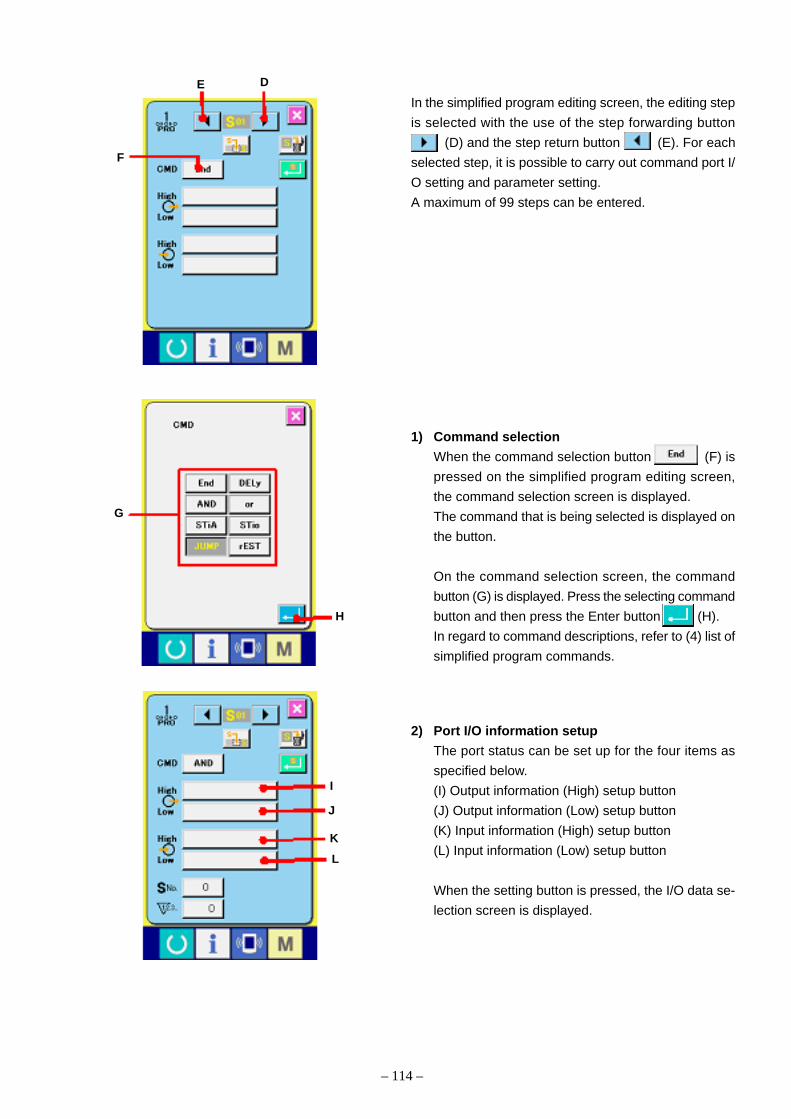
– 114 –
In the simplified program editing screen, the editing step
is selected with the use of the step forwarding button
(D) and the step return button (E). For each
selected step, it is possible to carry out command port I/
O setting and parameter setting.
A maximum of 99 steps can be entered.
DE
F
G
H
I
J
K
L
1) Command selection
When the command selection button (F) is
pressed on the simplified program editing screen,
the command selection screen is displayed.
The command that is being selected is displayed on
the button.
On the command selection screen, the command
button (G) is displayed. Press the selecting command
button and then press the Enter button (H).
In regard to command descriptions, refer to (4) list of
simplified program commands.
2) Port I/O information setup
The port status can be set up for the four items as
specified below.
(I) Output information (High) setup button
(J) Output information (Low) setup button
(K) Input information (High) setup button
(L) Input information (Low) setup button
When the setting button is pressed, the I/O data se-
lection screen is displayed.

– 115 –
On the port setup screen, current setting items are dis-
played at the top left of the screen.
: Output information (High) setup screen
: Output information (Low) setup screen
: Input information (High) setup screen
: Input information (Low) setup screen
Using the page turning buttons (M, L), the
displayed port type can be changed.
The port comes in the four types as specified below.
: Output port No.
: Input port No.
: Virtual I/O port No.
etc.: Presser SW 1 to 4, Start SW, Temporary stop
SW
The port No. button is displayed on the screen. Press
the button that corresponds to current setting.
The selection status button is displayed in gray.
After selection, press the Enter button (O).
M L
O
For output setting, press the output button (P) to
obtain the item for which the displayed step has been
set up. Therefore, this item can be examined.P

– 116 –
3) Parameter input
Corresponding to the selected command, the param-
eter input button is displayed.
When the parameter input button (Q) is pressed, the
parameter input screen is displayed.
Enter a numerical input through the ten key (R) and
press the Enter button (S).
In regard to the parameters that correspond to the
commands, refer to (4) list of simplified program com-
mands.
Q
R
S
T
U
4) Step insertion
It is possible to insert a step before the displayed
step.
When the step insertion button (T) is pressed,
the command selection screen is displayed.
Select the command that is required to be inserted,
and press the Enter button (U). Then, the
required step is inserted.

– 117 –
5) Step deletion
It is possible to delete the step that has been dis-
played.
When the step deletion button (V) is pressed,
the deletion check screen is displayed. When the
Enter button (W) is pressed, the displayed step
is deleted and the step standing behind is shifted
forward.
6) Checking the status of the simplified program in
the sewing screen
The simplified program button (A) is displayed
in the sewing screen if this simplified program is avail-
able. The simplified program select screen is pre-
sented and the effective simplified program button
(B) is displayed.
Select the simplified program number the status of
which is being checked, and press the ENTER but-
ton (C).
The simplified program confirmation screen is pre-
sented and the present step number and the status
of I/O are displayed.
The port number without I/O confirmation is displayed
in gray (D).
W
V
A
B
C
D

– 118 –
5. To use the simplified program with CP-20
(1) Simplified program ON/OFF
1) When the power supply is turned on with the key kept pressed, the unit is started in simplified program
mode.
2) When the key is pressed, the simplified program number and the ON/OFF status are displayed.
Using the , key, it is possible to select the simplified program number.
~
Using the key, ON/OFF changeover is possible.
⇔
Upon the completion of modification, turn off the power supply.
(2) Write/read of the simplified program data with the smart media
1) When the power supply is turned on with the key kept pressed, the unit is started in simplified program
mode.
2) When the key is pressed, write/read of the simplified program data becomes possible with the smart
media.
P1
P2

– 119 –
3) Select data Write or Read with the key.
: Reading : Writing
4) Using the , key, it is possible to select the file number.
1. For data reading
It is possible to select only the file number registered in the smart media.
~
2. For data writing
It is possible to select only the file number that is not registered in the smart media.
~
5) When the key is pressed, reading or writing is started. During data reading or writing, the File No. is
indicated in blinking mode. When the Power OFF is indicated, data writing is finished. Ordinary operation is
recovered when the power supply is turned on again.

– 120 –
(4) List of Simplified Program CommandsNo. Function code Command Output information Input information Parameter 1 Setting range Parameter 2 Setting range Remarks
1 End Complete Effective Ineffective Ineffective – Ineffective – Program execution is finished.
2 DELy Delay Effective Ineffective Ineffective – Delay time 0 to 9999ms Moving to the next step after the lapse of a delay time.
3 And Branch with AND condition Effective Effective Skip destination 1 to 99 steps Delay time 0: Input waiting till the Moving to the next step when all conditions specifiedNo. condition established by input setting are satisfactory (AND input).
1 to 9999ms Jumping to the step preset by skip destination No.after the lapse of a delay time as a result of failurein establishing the input conditions.
4 or Branch with OR condition Effective Effective Skip destination 1 to 99 steps Delay time 0: Input waiting till the Moving to the next step when either condition specifiedNo. condition established by input setting is satisfactory (OR input).
1 to 9999ms umping to the step preset by skip destination No.after the lapse of a delay time as a result of failurein establishing the input conditions.
5 STiA Branch with AND condition Effective Effective Skip destination 1 to 99 steps Number of 0 to 9999 stitches Moving to the next step after the lapse of the pre-for No. of stitches No. stitches set number of stitches. Jumping to the step specified
by the skip destination No. within the range of thepreset number of stitches when all conditions specifiedby input setting are satisfactory (AND input).
6 STio Branch with OR condition Effective Effective Skip destination 1 to 99 steps Number of 0 to 9999 stitches Moving to the next step after the lapse of the presetfor No. of stitches No. stitches number of stitches. Jumping to the step specified
by the skip destination No. within the range of thepreset number of stitches when either conditionspecified by input setting is satisfactory (OR input).
7 JUMP Jump repetition counter Effective Ineffective Skip destination 1 to 99 steps Repetition 0: Infinite Repeated in the range of skip destination steps specifiedNo. counting 1 to 9999 times by Jump till repetition counter carryover.
value Infinite loop is performed when setting is made at 0.Moving to the next step after repetition counter carryover.(Caution) Do not perform nest input of this command.
8 rEST Program reset Effective Ineffective Program No. 1 to 5 programs Ineffective – In the case of the step initialization of the specifiedprogram number, the specified program steps areforcedly returned to the initial steps.
Input information setup range Contents
o01H to o16H High output of external output terminals 01 to 16
v01H to v16H High output of virtual I/O ports 01 to 16
o01L to o16L Low output of external output terminals 01 to 16
v01L to v16L Low output of virtual I/O ports 01 to 16
Input information setup range Contents
o01H to o16H High status input of external output terminals 01 to 16
i01H to i16H High status input of external input terminals 01 to 16
v01H to v16H High status input of virtual I/O ports 01 to 16
p1H to p4H,sH,eH High status input of presser SW1 to 4 (p), Start SW (s), Temporary stop SW (e)
o01L to o16L Low status input of external output terminals 01 to 16
i01L to i16L Low status input of external input terminals 01 to 16
v01L to v16L Low status input of virtual I/O ports 01 to 16
p1L to p4L,sL,eL Low status input of presser SW1 to 4 (p), Start SW (s), Temporary stop SW (e)

– 121 –
Terminal Contents Remarksoutput
o01 1: Feeding frame right Standard
o02 2: Feeding frame left Standard
o03 4: Feeding frame Standard
2-step stroke
o04 7: Inverting shaft Standard
o05 9: Needle cooler Standard
o06 (Stacker material open) Simplified program output
o07 (Stacker material clamp) Simplified program output
o08 (Stacker material payout) Simplified program output
(5) Program sample
1) Simplified stacker program 1his is an example of program establishment intended to make material stacking, to be
done simultaneously with feeding frame lifting after the completion of sewing.
[Port I/O Setup]
Terminal Contents Remarksoutput
i01
i02
i03
i04
i05
i06
i07
i08
Virtual I/O I/O Contents Remarks
v01 Output 101: After sewing start point reset
v02
v03
v04
v05
v06
v07
v08
(Caution) For the descriptions in the parentheses ( ) of o06 ~ o08 above, the terminals directly generate outputs with the aid of the simplified program. Port I/O setting isdisabled.
[Simplified Program Setup]
End,DELy, o01H to o16H o01L to o16L Delay time: Unit of 1msAnd,or, o01H to o16H o01L to o16L i01H to i16H i01L to i16L Pn. Program No. Number of stitches: Unit of 1 stitch
STiA,Stio, v01H to v16H v01L to v16L v01H to v16H v01L to v16L Sn, Step NoJUMP,Rest p1H to p4H,sH,eH p1L to p4L,sL,eL
d. Delay timec. Number of stitchesr. Repetition counter
Step
No. Command Output information High Output information Low Input information High Input information Low Parameter 1 Parameter 2 Remarks
1 And v01L d.0 Waiting till sewing start point reset
2 DELy o06L,o07L d.200 Stacker material open / material clamp ON. 200ms delay.
3 DELy o08L d.400 Stacker material payout ON. 400ms delay.
4 DELy o06H,o08H d.300 Stacker material open / material payout OFF. 300ms delay.
5 JUMP o07H Sn.1 r.0 Stacker material clamp OFF. To Step 1.
6 End
After sewing start point reset
Stacker material open
Stacker material clamp
Stacker material payout
200ms 400ms 300ms

– 122 –
2) Stacker program 2This is an example of program establishment intended to make material stacking, to be done after the material cloth has been clamped before feeding frame liftingat the time of the completion of sewing.
Terminal output Contents Remarks
o01 1: Feeding frame right Standard
o02 2: Feeding frame left Standard
o03 4: Feeding frame 2-stage stroke Standard
o04 7: Reverse shaft Standard
o05 9: Needle cooler Standard
o06 (Stacker move) Simplified program output
o07 (Stacker material clamp) Simplified program output
o08 (Stacker material stack) Simplified program output
[Port I/O Setup]
Terminal input Contents Remarks
i01
i02
i03
i04
i05
i06 (Stacker movement sensor) Simplified program input
i07 (Stacker material clamp sensor) Simplified program input
i08
Virtual I/O I/O Contents Remarks
v01 Output 61: Sewing forwarded
v02 Output 102: Sewing machine started
v03 Output 100: Before sewing start point reset
v04 Output 101: After sewing start point reset
v05 Output 105: Before origin reset
v06 Input 55: Feeding frame lift/lower wait
v07
v08
(Caution) For the descriptions in the parentheses ( ) of o06 ~ o08 and i06 ~ i07 above, the terminals directly generate outputs with the aid of the simplified program. Port I/Osetting is disabled.
Sewing forwardedSewing machine started
Before sewing start point reset
After sewing start point reset
Before origin reset
Feeding frame lift/lower wait
Stacker movement
Stacker material clamp
Stacker material stacking
Normal operation When sewing interrupted
100ms
500ms
300ms
Stacker movement sensor
Stacker material clamp sensor

– 123 –
[Simplified Program Setup]
End,DELy, o01H to o16H o01L to o16L Delay time: Unit of 1msAnd,or, o01H to o16H o01L to o16L i01H to i16H i01L to i16L Pn. Program No. Number of stitches: Unit of 1 stitch
STiA,Stio, v01H to v16H v01L to v16L v01H to v16H v01L to v16L Sn, Step NoJUMP,Rest p1H to p4H,sH,eH p1L to p4L,sL,eL
d. Delay timec. Number of stitchesr. Repetition counter
Step
No. Command Output information High Output information Low Input information High Input information Low Parameter 1 Parameter 2 Remarks
1 And v01L , v02L d.0 Waiting till sewing machine start.
2 or o06L, v03L, v05L d.0 Stacker movement ON. Waiting till sewing start point
reset or origin reset.
3 And v03L Sn.11 d.1 To Step 11 if there is no sewing start point reset.
4 And v06L v04L d.0 Feeding frame lifting wait ON. Waiting till sewing start
point reset.
5 And i06 d.0 Waiting till stacker movement sensor ON.
6 And o07L i07 d.0 Stacker material clamp ON. Waiting till stacker mate-
rial clamp sensor ON.
7 DELy v06H d.100 Feeding frame lifting wait ON. 100ms delay.
8 DELy o06H d.500 Stacker movement OFF. 500ms delay.
9 DELy o08L d.300 Stacker material stacking ON. 300ms delay.
10 JUMP o07H, o08H Sn.1 r.0 Stacker material clamp / material stacking OFF.
11 JUMP o06H Sn.1 r.0 Stacker movement OFF. To Step 1.
12 End

– 124 –
Terminal Contents Remarks
output
o01
o02
o03
o04
o05
o06
o07
o08
o09
o10
o11
o12
o13
o14
o15
o16
(6) Port I/O setup sheetTerminal Contents Remarks
input
i01
i02
i03
i04
i05
i06
i07
i08
i09
i10
i11
i12
i13
i14
i15
i16
Virtual I/O I/O Contents Remarks
v01
v02
v03
v04
v05
v06
v07
v08
v09
v10
v11
v12
v13
v14
v15
v16

– 125 –
End,DELy, o01H to o16H o01L to o16L Delay time: Unit of 1msAnd,or, o01H to o16H o01L to o16L i01H to i16H i01L to i16L Pn. Program No. Number of stitches: Unit of 1 stitch
STiA,Stio, v01H to v16H v01L to v16L v01H to v16H v01L to v16L Sn, Step NoJUMP,Rest p1H to p4H,sH,eH p1L to p4L,sL,eL
d. Delay timec. Number of stitchesr. Repetition counter
Step
No. Co. Command Output information High Output information Low Input information High Input information Low Parameter 1 Parameter 2 Remarks
1
2
3
4
5
6
7
8
9
0
1
2
3
4
5
6
7
8
9
0
(7) Simplified program setup sheet

– 126 –
(6) Version display
1. To display the version information screen:Hold down the key for 3 seconds to call up theversion information button, (A) on the screen.Press this button to display the version informationscreen.
The version information screen shows the versioninformation of your sewing machine.
B: Panel program versionC: Main program versionD: Main shaft program version
Pressing the cancel button, (E) closes the ver-sion information screen and calls up the mode screen.
2. To display the detail screen:Press the detail screen button, (F) to call up thepanel program detail screen.
G: ModuleH: RVLI: Checksum
Pressing the cancel button, (J) closes the detailscreen and calls up the version information screen.Pressing the key closes the detail screen andcalls up the data input screen which you have se-lected.
A
B
C
D
E
F
J
I
G H
* The check program allows you to see version information on the simplified panel.

– 127 –
(7) Keylock setup
1. To call up the keylock screen:
Hold down the key for 3 seconds to call up the
keylock button, (A) on the screen. Press this
button to display the keylock setting screen.
The current status appears on the keylock button.
: Keylock is inactivated.
: Keylock is activated.
2. To select keylock and activate it:
Select the keylock activation button, (B) on the
keylock setting screen and press . Then, the
keylock setting screen closes and keylock becomes
activated.
3. After closing the mode screen and calling up the
data input screen:
After closing the mode screen and calling up the data
input screen, PICT C indicating that keylock is acti-
vated appears on the right of the pattern number.
Only available buttons appear when keylock is acti-
vated.
* Memory switch No. 17 allows you to activate keylock
on the simplified panel.
B
C
C
A

– 128 –
(8) Communication screens of the maintenance personnel level (Program rewrite)
The data types allowed to be handled in the communication screens can differ according to the ordinarily usedlevels and the specific levels that are used by the maintenance personnel.
1. Types of data that can be handledIn addition to the four ordinary data types, the five more data types can be used for the maintenance personnellevel. Each data type is as specified below.
Data name Pict Extension Contents of data
Adjustment data Model name +00XXX.MSW Data of the memory switches 1 and 2
Example) AMS00001.MSW
All sewing machine data Model name +00XXX.MSP All data maintained by the sewing machine
Example) AMS00001.MSP
Panel program data IP + RVL (6 digits).HED Program data and display data of the panel
IP + RVL (6 digits).PXX
IM + RVL (6 digits).IXX
Main program data MA + RVL (6 digits).PRG Main program data
Servo program data MT + RVL (6 digits).PRG Servo program data
XXX: File No.

2. Reading/Writing of adjustment data and all sew-
ing machine data (For the IP-400)
(1) Display of the communication screen of the main-
tenance personnel level
When the key (A) is continuously pressed for 3seconds, the top left image is turned into the orangecolor (B) and a communication screen of the mainte-nance personnel level is displayed. (C) is pressed in a communication screen ofthe maintenance personnel level, the data selectionscreen is displayed.In this state, it becomes possible to select the ad-
justing data and all sewing machine data.
3. Program rewriting (For the IP-400)
(1) Selection of the data type
When the data classification button (C) is
pressed in a communication screen of the mainte-
nance personnel level, the data selection screen is
displayed.
In this state, select the panel program data (D).
(2) Selection of a file
When the file selection button (E) is pressed in
a communication screen, the file selection screen is
displayed.
Press the file retrieval button (F) to select the
download program (G), and press the button.
– 129 –
B
C
A
D
E
FG

– 130 –
(3) Program rewrite start
When the start of communication button (H) is
pressed, program rewriting is started.
(Caution) Never turn off the power or open/shut the
smart media cover during the work. Oth-
erwise, the main body can be destroyed.
H
When the ending screen is displayed, the replacement
work for the application software has been completed.
If any data writing error screen should be displayed, im-
mediately turn off the power supply and check the [check-
ing items] specified below. Then, take the setup actions
again.
[Checking items]
1) Did you open the smart media cover in the middle of
data communication from the smart media card.
2) Data of the smart media card are incorrect, or there
is no data file.
3) The contact point of the smart media card is contami-
nated, or suffering from poor contact.
Data deleting screen Data writing screen
Ending screen
Data writing error screen

– 131 –
4. Reading/Writing of the adjustment data and all sewing machine data in the smart media (For the CP-20)
(1) When the power is turned on with the key kept pressed, the adjustment data mode is started. When the
adjustment data mode is started, the pattern number LED is lit up.
When the power is turned on with the key kept pressed, the all sewing machine data mode is started. When
the all sewing machine data mode is started, the X scale LED is lit up.
: Adjustment data mode : All sewing machine data mode
(2) Select data reading or writing with the key
: Reading : Writing
(3) Select the fine number with the and keys.
1) For reading
Selection is made possible only for the file number that is registered in the smart media.
to
2) For writing
Selection is made possible only for the file number that is not registered in the smart media.
to
(4) When the key is pressed, reading or writing of each data block is started. In the middle of data reading or
writing, the file number is displayed in the blinking mode. When Power OFF is displayed, reading or writing has
been completed.
(5) When the power supply is turned on again, normal operation is recovered.

– 132 –
5. Program rewriting (For the CP-20)
(1) When the power is turned on with the key kept pressed, the rewriting mode of the simplified panel program
is started. When the rewriting mode of the simplified panel program is started, the Y scale LED is lit up.
When the power is turned on with the key kept pressed, the rewriting mode of the main program is started.
When the rewriting mode of the main program is started, the max. number of rotation LED is lit up.
When the power is turned on with the key kept pressed, the rewriting mode of the servo program is started.
When the rewriting mode of the servo program is started, the tension LED is lit up.
: Panel program : Main program : Servo program
(2) Using the key, select the program file for the panel, which is kept in the smart media. In regard to the file
display, the key can be used for changeover between the RVL display and the model code display.
: RVL display : Model code display
For RVL display, five digits of R (1 digit), V (2 digits), and L (2 digits) are displayed.
The non-display portion (RVL + α) can be displayed with the use of the and keys.
Example) RVL 01-03-02
For model code display, the five continued characters from the head are displayed.
The model code of the non-display portion can be displayed with the use of the and keys.
Example) AMS-210E
(3) When the key is pressed, writing of the simplified panel program is started. When Power OFF is displayed,
writing has been completed.
When the power supply is turned on again, normal operation is recovered.

– 133 –
6. Use of smart media other than those packed together
When the contents of the smart media card packed together are going to be copied on another smart media card,
the smart media card of the copying destination should be formatted with IP400. Since then, the following directory
configuration should be established with a personal computer.
Information about the method of smart media card formatting is obtainable from the Instruction Manual, [2-25. How
to Use the Communication Functions].
Route directory [PROG] [AMS210E] MTxxxxxx.prg (Servo program)
MAxxxxxx.prg (Main program)
[IPxxxxxx] (IP-400 program)
IPxxxxxx.hed
IPxxxxxx.p01
IMxxxxxx.i01
IMxxxxxx.i10
IMxxxxxx.i11
IMxxxxxx.i12
IMxxxxxx.i13
IMxxxxxx.i21
IMxxxxxx.i22
IMxxxxxx.i23
NPxxxxxx.prg (CP-20 program)
[ ] = Folder
xxxxxx = RVL code (6 digits)

– 134 –
(9) Information screen at the maintenance personnel level
1. Error history
(1) To display the information screen at the mainte-
nance personnel level:
Hold down the information key, (A) for approx. 3
seconds in the switch sheet section on the data in-
put screen to call up the information screen at the
maintenance personnel level. On the information
screen at the maintenance personnel level, the color
of PICT at the upper left changes from blue to or-
ange, and there are 5 buttons.
(2) To call up the error history screen:
Press the error history button, (B) on the infor-
mation screen to call up the error history screen.
The error history screen shows the error history of
your sewing machine.
C: Chronological recording number
D: Error code
E: Cumulative energizing time during error (hour)
Pressing the cancel button, (G) closes the error
history screen and calls up the information screen.
(3) To display details:
For detailed information about errors, press the er-
ror button, (F) that you would like to
see to call up the error detail screen.
PICT (H) in response to error codes appears on the
error detail screen.
→ Refer to the “11. ERROR CODE LIST”.
B
D
H
A
C
G
E
F

– 135 –
2. Cumulative operating information
(1) To call up the information screen at the mainte-
nance personnel level:
Hold down the information key , i for approx. 3
seconds in the switch sheet section on the data in-
put screen to call up the information screen at the
maintenance personnel level. On the information
screen at the maintenance personnel level, the color
of PICT at the upper left changes from blue to or-
ange, and there are 5 buttons.
(2) To display cumulative operating information:
Press the cumulative operating information button,
(A) on the information screen to call up the cu-
mulative operating information screen.
The following 4 items are indicated on the cumula-
tive operating information screen.
B: Cumulative operating time (hour)
C: Cumulative thread trimming count
D: Cumulative energizing time (hour)
E: Cumulative stitch count (x1000 stitches)
Pressing the cancel button, (F) closes the cumu-
lative operating information screen and calls up the
information screen.
F
A
C
E
B
D

– 136 –
(10) Test sewing functionConnecting your PC to the sewing machine allows you to perform test sewing based on data created with PM-1
(sewing data creating and editing software).
IP400IP400
P M - 1P M - 1
Connect your PC and transmit data to the sewing machine after creating it with PM-1, and IP-400 automaticallyshows the test sewing screen when the data input screen is called up. Refer to the help screen or the like for howto operate PM-1.
Data transmission
1. To perform test sewing:
(1) Reception of data for test sewing from PM-1When data (vector type) for test sewing is transmit-ted from PM-1, the screen shown at right appears,and a needle positioning drawing of transmitted dataappears in the center of the screen.The color of the needle positioning drawing changesdepending on thread tension. If the stitch count oftransmitted data is too large, a needle positioningdrawing does not appear.
(2) Edit of vector parameterThe following 3 items are configurable on data trans-mitted from PM-1.
A: Thread tensionB: X-axial enlargement/reduction ratio or actual valueC: Y-axial enlargement/reduction ratio or actual value
* The memory switch, U64, provides selection betweenan enlargement/reduction ratio and an actual value.
A
B C

(6) Confirmation of data registrationPress the enter button (H) to close the regis-tration screen, and registration is completed.
(5) Data registration to user patternTo register test sewing data to the sewing machine,press the registration button (F) shown on thetest sewing screen to call up the registration screen.Enter the user pattern number to which the test sew-ing data is registered with the numeric keypad (G).
– 137 –
(3) Modification to dataPress the button, A, B, or C to be changed to call upthe numeric keypad. Enter a new value and pressthe enter button (D).
E
F
D
H
G
(4) Test sewingPress the ready-to-go switch (E) to call up thetest sewing screen. Test sewing is ready.
(7) data entry screenAfter data registration, the data entry screen auto-matically appears.
A
B C
D
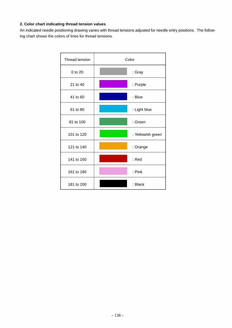
– 138 –
2. Color chart indicating thread tension values
An indicated needle positioning drawing varies with thread tensions adjusted for needle entry positions. The follow-
ing chart shows the colors of lines for thread tensions.
Thread tension Color
0 to 20 : Gray
21 to 40 : Purple
41 to 60 : Blue
61 to 80 : Light blue
81 to 100 : Green
101 to 120 : Yellowish green
121 to 140 : Orange
141 to 160 : Red
161 to 180 : Pink
181 to 200 : Black

– 139 –
6. Test mode(1) Start (CP-20)
When the check program is started, maintenance and inspection can be carried out.
1) Check program start
1. When the key is continuously pressed for 3 seconds in the state that thesewing LED is unlit, a buzzer sound is heard and the user setup mode is assumedfor the memory switch. In this state, ìcheck program startî can be selected.(Caution) The check program cannot be selected unless this key is continu-
ously pressed for 3 seconds.
2. Change the memory switch number with the and keys to select thecheck program.
3. Press the key to move to the check program. Start the display output test.Refer to the next page in regard to the contents of the display output test.
4. Press the key to complete the display output test. Move to the selection ofanother test function.
5. Select the check program number with the and keys.
Check program number Check program Contents
Input signal check The status of the switch and sensor inputs is displayed
at LED.
XY motor / origin sensor The status of inching operation of the X/Y motor,
check operation of origin retrieval, and the X/Y origin sensors
is displayed.
Continuous operation After the conditions of continuous operation have been
et up, the operational mode moves to the continuous
operation mode.
Main motor rpm check The sewing machine is started at the preset rpm level
nd the measured rpm number is displayed.

– 140 –
Check program number Check program Contents
Output check The wiper and air outputs are generated.
Presser, thread cutter motor/ The status of inching operation of the presser and
origin sensor check thread trimmer motor, operation of origin retrieval, and
he presser origin / presser sensors is displayed.
Needle thread clamp motor/ The status of inching operation of the needle thread
origin sensor check clamp motor, operation of origin retrieval, and the needle
thread clamp origin and needle thread clamp sensors is
displayed.
Intermediate presser The status of inching operation of the intermediate
adjustment presser motor, operation of origin retrieval, and the
intermediate presser origin sensors is displayed.
Software version display The software versions of the MAIN and SDC boards
are displayed.
6. Press the key to define the check program number.
7. When the key is pressed for each check program, the current check program is completed and the statusof 5. is recovered.Once the continuous operation mode is started, it cannot be canceled. To complete it, however, it is necessary toturn the power supply OFF.

– 141 –
(2) Display output test (CP-20)
After the movement to a check program, the display output test is started.
The following LEDs are lit at the intervals of one second.

P 5
P 1 P 2 P 3 P 4 P 5
Pattern X enlarge Y enlarge Speed Counter Bobbin Threading Thread tension Ready Thread clamp
LED LED LED LED LED LED LED LED LED LED
1
Key Key Key Key Key Key
2
Key Key Key Key Key Key
3 DIPSW2 DIPSW2 DIPSW2 DIPSW2 Start SW Presser Presser Presser Presser
-1 -2 -3 -4 1SW 2SW 3SW 4SW
4 AUDET ADDET DDET UDET TG PDET SDET Head fall Air pressure X motor origin
Sensor Sensor Sensor Sensor Sensor Sensor Sensor SW SW Sensor
5 Y motor Presser motor Thread clamp Intermediate Presser Thread External External External External
origin origin motor presser motor motor clamp motor input 1 input 2 input 3 input 4
sensor sensor origin sensor origin sensor sensor sensor
6 External External External External External External External External External External
input 5 input 6 input 7 input 8 input 9 input 10 input 11 input 12 input 13 input 14
7 External External
input 15 input 16
8
(3) Method of confirmation according to each test program No. (CP-20)
– 142 –
1) CP-1 (Input signal check)
It is possible to check the input status of the operation panel keys, pedal switches, and various sensors.
Display of input No.
The input number is updated by +1 each time the
and keys are pressed simultaneously.
Display of the input status with the item selection LEDON/OFFRefer to the table below in regard to the contents of dis-play.
Contents of Display for each Input No.
DIPSW2 is a dip switch located on the MAIN board.
TemporarystopSW

P 1 P 2 P 3 P 4 P 5
– 143 –
2) CP-2 (XY motor / origin sensor check)
The status of inching operation of the X/Y motor, operation of origin retrieval, and the X/Y origin sensors is
displayed.
1. In the first place, press the key to carry out needle thread clamping and origin retrieval for the presser and
thread trimmer motor. The presser assumes the lowering condition.
After the completion of preparation, the sewing LED is lit.
2. Operation
3) CP-3 (Continuous operation)After the conditions of continuous operation have been set, the opera-tional mode moves to the continuous operation mode.To cancel the continuous operation mode, it is necessary to turn thepower supply OFF.
1. Rest time setting
Press the and keys to set up the rest time.
Setting is possible within the range of 0 to 9900ms in the unit of 100ms.
(Initial value 2000ms)
After the completion of setting, press the key.
2. Setting for the presence of origin retrieval at the end of sewing
Press the and keys to set up the presence of origin retrieval
at the end of sewing.
A0: Ineffective (Initial value)
A1: Every 100 sewing cycles
A2: Every sewing cycle
Using the Start SW, origin retrieval of the X/Y motors is effected for both shafts.
According to the status of the selected X/Y origin sen-
sor, “0” or “1” is displayed. The key is pressed to
make changeover.
Using the and keys, drive the selected X/Y
motor in the direction of +/– by 0.1mm each time.
(Caution) Since the circular interpolation system is
used, any motor not selected is also driven.
The selection status of the X motor (X origin sensor) or
the Y motor (Y origin sensor) is displayed. The key
is pressed to make changeover.
X enlargement/reduction scale rate LED lit: X motor (X
origin sensor)
Using the key, the selection status of the X motor
(X origin sensor) or the Y motor (Y origin sensor) is
changed over.

– 144 –
3. Presser lifting, Lowering frequency vertical times setup
Press the and keys to set up the presser vertical times.
B0: Ineffective (Initial value)
B1 ~ B10: 1 to 10 times
After setting, press the key. The ordinary display is recovered.
4. Continuous operation
After the completion of setting, regular operation like pattern number setup and others should be carried out.
At the end of sewing, origin retrieval of each motor is carried out for the X/Y / presser and thread trimmer /
needle thread clamp if “origin retrieval effective” has been selected as per 2. Then, automatic sewing is
restarted after the lapse of the rest time preset as per 1. above.
To stop continuous operation, the start switch should be turned ON during the rest time. [E 50] is displayed
and the machine is stopped.

P1 P2 P3 P4 P5
– 145 –
4) CP-4 (Main motor rpm check)Set up the rpm number of the sewing machine, drive only the main motor of the sewing machine at the presetrpm level, and display the measured rpm number.
1. READY operationIn the first place, press the key for the origin retrieval of the needle thread clamp and the presser and threadtrimmer motor. After operation for preparation, the sewing LED is lit.
2. Operation
When the key is pressed, the sewing machine is
actuated at the preset rpm level.
If the rpm number is changed in the middle of sewing
machine operation, the speed can be changed by press-
ing the key.
When the key is pressed, the sewing machine
stops.
The preset rpm number or the actually measured rpm
number is displayed. Changeover is possible by press-
ing the key.
Using the and keys, the rpm number can be
preset within the range of 400 to 2700 rpm. This setting
is possible even in the middle of sewing machine opera-
tion.
The speed LED is unlit while the preset rpm number is
displayed, and is lit while the measured number is dis-
played. Changeover can be made by pressing the
key.
With the key, the speed display can be changed
over between the preset and the measured rpm num-
ber.

P 5
P 1 P 2 P 3 P 4 P 5
P 1 P 2 P 3 P 4 P 5
5) CP-5 (Output check)
1. Operation
– 146 –
6) CP-6 (Presser and thread trimmer motor / origin sensor check)
The status of inching operation of the presser and thread trimmer motor, operation of origin retrieval, and the
presser origin and thread trimmer sensors is displayed.
1. READY operation
In the first place, press the key for the origin retrieval of the needle thread clamp.
After operation for preparation, the sewing LED is lit.
2. Operation
The key is used to drive the presser and thread
trimmer motor to each preset position.
1Presser lifting position
2Presser lowering position (lowering position during
pedal operation)
3Thread trimmer position
4Presser lowering position (lowering position after
thread trimming)
When the key is pressed while the key is
kept pressed, the motor is driven reversely.
According to the status of the thread trimmer sensor, “0” or “1” is displayed.
The checking items can be changed with the and
keys.
In regard to the items, refer to the section of IP-400 output
check.
An output is generated while the key is pressed.
According to the status of the presser origin sensor, “0” or “1” is displayed.
Using the and keys, the presser and thread
trimmer motor can be driven by one pulse in the +/– di-
rection.
The START Switch is used for the origin retrieval of the presser and thread trimmer motor.

P 1 P 2 P 3 P 4 P 5
P 1 P 2 P 3 P 4 P 5
– 147 –
7) CP-7 (Needle thread clamp motor / origin sensor check)
The status of inching operation of the needle thread clamp motor, operation of origin retrieval, and the thread
clamp origin and needle thread clamp sensors is displayed.
1. Operation
8) CP-8 (Intermediate presser adjustment)
The status of inching operation of the intermediate presser motor, operation of origin retrieval, and the thread
clamp origin and intermediate presser origin sensor is displayed.
1. Operation
The key is used to drive the needle thread clamp
motor to each preset position.
1Standby position (front side)
2Needle thread bending position
3Needle thread clamp position
4Refuge position (rear side)
According to the status of the needle thread clamp sensor, “0” or “1” is dis-
played.
Using the and keys, the needle thread clamp
motor can be driven by one pulse in the +/– direction.
According to the status of the thread clamp origin sensor, “0” or “1” is dis-
played.
The key is used to drive the needle thread clamp
motor to each preset position.
1Lower position at the height of 7mm during lowering
2Timing adjustment position
3Lower position at the height of 0mm during lowering
4Intermediate presser bar adjustment position
Using the and keys, the needle thread clamp
motor can be driven by one pulse in the +/– direction.
According to the status of the intermediate presser origin sensor, “0” or “1” is
displayed.
The START Switch is used for the origin retrieval of the needle thread clamp motor.
The START Switch is used for the origin retrieval of the intermediate presser motor.

– 148 –
9) CP-9 (Software version display)
The software versions of the PANEL Board, the MAIN Board, and the SDC Board are displayed.Each version is expressed in a format of RR, VV, LL-xx. xx is used to indicate the specifications for special
orders, etc. Therefore, it is not indicated usually.
1. Operation
P 1 P 2 P 3 P 4 P 5
According to the item selection LED, the RVL display(RR, VV, LL-xx) for the PANEL Board, the MAIN Board,and the SDC Board, and also the model code display ispresented. The and keys can be used for thescroll display.
Example) RVL 01.03.02
Example) AMS-210E
The key is used for the cyclic display of the PANELBoard, the MAIN Board, and the SDC Board.
: Panel program
: Main program
: Servo program
The key is used for the cyclic display of the RVLdisplay and the model code display.
When the LED is unlit: RVL display
When the LED is lit: Model code display

– 149 –
(4) For IP-400
1) Display of the check program screen
When the key is continuously pressed for 3
seconds, the check program (A) is displayed on
the screen. When this button is depressed, the check
program screen is displayed.
The check program comes in the ten items as specified
below.
Touch panel correction screen
→ The touch panel and button display positions are
corrected.
LCD check
→ Presence of any dot missing is checked for the liq-
uid crystal display.
Input signal check
→ The status of switches and sensor inputs is dis-
played.
Main motor rpm check
→ When the sewing machine is started at the preset
rpm level, the measured rpm value is displayed.
Output check
→ Wiper and air output check is carried out.
XY motor / origin sensor check
→ The status of inching operation of the X/Y motor,
operation of origin retrieval, and the X/Y origin sen-
sor is displayed.
A
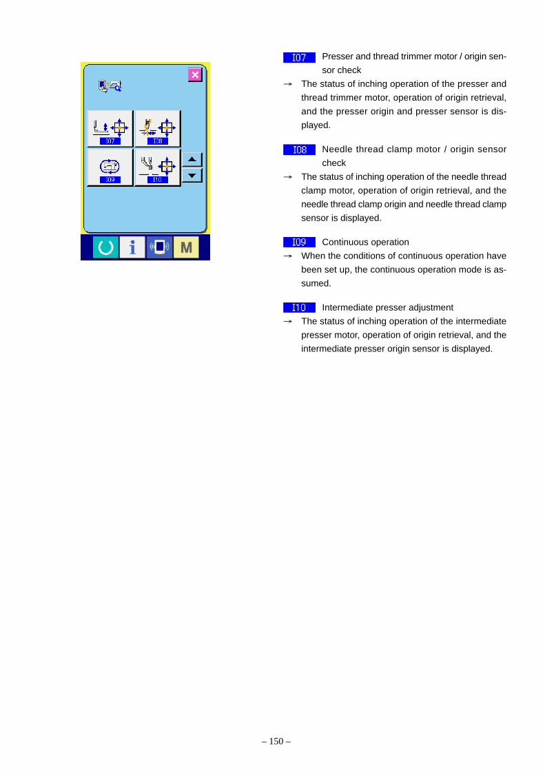
– 150 –
Presser and thread trimmer motor / origin sen-
sor check
→ The status of inching operation of the presser and
thread trimmer motor, operation of origin retrieval,
and the presser origin and presser sensor is dis-
played.
Needle thread clamp motor / origin sensor
check
→ The status of inching operation of the needle thread
clamp motor, operation of origin retrieval, and the
needle thread clamp origin and needle thread clamp
sensor is displayed.
Continuous operation
→ When the conditions of continuous operation have
been set up, the continuous operation mode is as-
sumed.
Intermediate presser adjustment
→ The status of inching operation of the intermediate
presser motor, operation of origin retrieval, and the
intermediate presser origin sensor is displayed.

– 151 –
2) Touch panel correction
1. Display of the touch panel correction screen
When the touch panel correction button (A) of
the check program screen is pressed, the touch panel
correction screen is displayed.
2. Pressing the bottom left position
Press the red circle (C) located at the bottom left
of the screen. To complete correction, press the can-
cel button (B).
3. Pressing the bottom right position
Press the red circle (D) located at the bottom
right of the screen. To complete correction, press the
cancel button (B).
B
D
B
A
C

– 152 –
4. Pressing the top left position
Press the red circle (E) located at the top left of
the screen. To complete correction, press the cancel
button (B).
5. Pressing the top right position
Press the red circle (F) located at the top left of
the screen. To complete correction, press the cancel
button (B).
6. Data saving
When all the four points have been pressed, the cor-
rection data are saved. At that time, the Power OFF
Prohibition screen is displayed.
The power supply must not be turned off while the
above-mentioned screen is displayed.
If the power supply is carelessly turned off, no cor-
rection data are saved.
After data saving, the check program screen is auto-
matically displayed.
E
B
F
B

– 153 –
3) LCD check
1. Display of the LCD check screen
When the LCD check button (A) is pressed on
the check program screen, the LCD check screen is
displayed.
2. Confirmation of LCD dot missing
The LCD check screen is displayed only in one color.
In this state, the LCD should be checked to freedom
from dot missing.
After this confirmation, press a proper position on
the screen. The LCD check screen is closed and the
check program screen is displayed.
A

– 154 –
4) Method of input signal check
1. Display of the input signal check screen
When the input signal check button (A) is
pressed on the check program screen, the sensor
check screen is displayed.
2. Input signal check
In the input signal check screen, the input condi-
tions of various sensors can be confirmed.
For each sensor, the input status is displayed as
indicated by B.
The ON/OFF conditions are displayed as shown
below.
: ON condition
: OFF condition
Using the UP-DOWN buttons (C), display
the sensor that has been confirmed.
A
B
C

– 155 –
The sensors provide the following 43 types of conditions:
No. Pictograph Contents of sensor No. Pictograph Contents of sensor
DIPSW2-1 SDET sensor
DIPSW2-2 Head fall SW
DIPSW2-3 Air pressure SW
DIPSW2-4 Thread breakage sensor SW
Start SW (Pedal) X motor origin sensor
Presser 1 SW (Pedal) Y motor origin sensor
Presser 2 SW (Pedal) Presser motor origin sensor
Presser 3 SW (Pedal) Needle thread clamp motor
origin sensor
Presser 4 SW (Pedal) Intermediate presser motor
origin sensor
Temporary stop SW Presser motor sensor
AUDET sensor Needle thread clamp motor
sensor
ADDET sensor External input 1
DDET sensor External input 2
UDET sensor External input 3
TG sensor External input 4
PDET sensor External input 5
The DIPSW2 is the DIPSW located on the MAIN Board.

– 156 –
No. Pictograph Contents of sensor No. Pictograph Contents of sensor
External input 6 External input 12
External input 7 External input 13
External input 8 External input 14
External input 9 External input 15
External input 10 External input 16
External input 11

– 157 –
5) Main motor rpm check
1. Display of the main motor rpm check screen
When the main motor rpm check button (A) is
pressed on the check program screen, the main
motor rpm check screen is displayed.
2. Main motor operation and measured rpm value
check
Using the –/+ buttons (B, C), the rpm
number can be set up. When the button (D) is
pressed, the sewing machine is operated at the pre-
set speed. At that time, the measured rpm value is
displayed at (E). When the SET button (F)
is pressed, the sewing machine is stopped.
A
B C
E
F
D

– 158 –
6) Method of output check
1. Display of the output check screen
When the output check button (A) is pressed on
the check program screen, the output check screen
is displayed.
2. Output check
The output check screen can be used for the output
check of each position. Try to press the output check
button (B). While this button is pressed, the ON-sta-
tus output is kept generated.
A
B

– 159 –
No. Pictograph Contents No. Pictograph Contents
Wiper Air output 9
Air output 1 Air output 10
Air output 2 Air output 11
Air output 3 Air output 12
Air output 4 Air output 13
Air output 5 Air output 14
Air output 6 Air output 15
Air output 7 Air output 16
Air output 8
The output check display provides the following 17 types of positions:

– 160 –
7) Method of XY motor / origin sensor check
1. Display of the XY motor / origin sensor check
screen
When the XY motor / origin sensor check button
(A) is pressed on the check program screen,
the XY motor / origin sensor check screen is dis-
played.
2. XY motor / origin sensor check
According to the status of the X/Y origin sensor, the
ON/OFF condition of the sensor is displayed in the
position of B.
When the Arrow-Mark button (C) is pressed,
the X/Y motor can be driven by 0.05mm in the +/–
direction.
(Caution) 1. Using the Start SW, origin retrieval of
the X/Y motors is effected for both
shafts.
A
B
C

– 161 –
8) Method of presser and thread trimmer motor /
origin sensor check
1. Display of the presser and thread trimmer mo-
tor / origin sensor check screen
When the presser and thread trimmer motor / origin
sensor check button (A) is pressed on the
check program screen, the presser and thread trim-
mer motor / origin sensor check screen is displayed.
2. Presser and thread trimmer motor / origin sen-
sor check
According to the status of the thread trimmer sensor,
the ON/OFF condition of the thread trimmer sensor
is displayed in the position of B.
According to the status of the presser origin sensor,
the ON/OFF condition of the presser origin sensor is
displayed in the position of C.
Using the [+] and [–] keys (D, E), the
presser / thread trimmer motor can be driven by one
pulse.
When the fixed position moving button (F) is
pressed, the presser / thread trimmer motor is driven
to any of the following fixed positions. A pictograph
indicating this position is displayed in gray.
G : Presser lifting position
H : Presser lowering position (lowering position
during pedal operation)
I : Thread trimmer position
J : Presser lowering position (lowering position
after thread trimming)
When the reverse rotation button (K) is pressed,
driving is conducted in reverse direction. Using the
Start SW, origin retrieval of the presser / thread trim-
mer motor is effected.
(Caution) The Start Switch becomes effective after
the completion of origin retrieval for the
presser / thread trimmer motor.
A
B
C
H
I
D E
G
J
K
F

– 162 –
9) Method of needle thread clamp motor / origin sen-
sor check
1. Display of the needle thread clamp motor / origin
sensor check screen is displayed.
When the needle thread clamp motor / origin sensor
check button (A) is pressed on the check
program screen, the needle thread clamp motor /
origin sensor check screen is displayed.
2. Needle thread clamp motor / origin sensor check
According to the status of the needle thread clamp
sensor, the ON/OFF condition of the needle thread
clamp origin sensor is displayed in the position of C.
According to the status of the needle thread clamp
origin sensor, the ON/OFF condition of the needle
thread clamp sensor is displayed in the position of
B.
Using the [+] and [–] buttons (D, E), the
needle thread clamp motor can be driven by one
pulse.
When the fixed position moving button (F) is
pressed, the needle thread clamp motor is driven to
any of the following fixed positions. A pictograph in-
dicating this position is reversed and displayed.
G : Standby position (front side)
H : Needle thread bending position
I : Needle thread clamp position
J : Refuge position (rear side)
Using the Start SW, origin retrieval of the needle
thread clamp motor is effected.
(Caution) The Start Switch becomes effective after
the completion of origin retrieval for the
needle thread clamp motor.
A
B
C
H
I
G
J
F
D E

– 163 –
10) Method of continuous operation
1. Display of the continuous operation screen
When the continuous operation button (A) is
pressed on the check program screen, the continu-
ous operation screen is displayed.
2. Continuous operation
In the continuous operation screen, the continuous
operation mode is set up.
B : Intervals of operation (rest time)
C : Origin retrieval at the end of sewing
0 : No
1 : Every 100 runs
2 : Every time
D : Presser lifting, lowering (frequency)
When the READY key is turned ON, continuous
operation is started.
If the READY key is turned ON again in the middle of
continuous operation, continuous operation is
stopped.
A
B
C
D

– 164 –
11) Method of intermediate presser motor / origin
sensor check
1. Display of the intermediate presser motor / ori-
gin sensor check screen
When the intermediate presser motor / origin sensor
check button (A) is pressed on the check
program screen, the intermediate presser motor /
origin sensor check screen is displayed.
2. Intermediate presser motor / origin sensor check
According to the status of the intermediate presser
origin sensor, the ON/OFF condition of the interme-
diate presser origin sensor is displayed in the posi-
tion of B.
Using the [+] and [–] buttons (C, D), the
intermediate presser motor can be driven by one
pulse.
When the fixed position moving button (E) is
pressed, the intermediate presser motor is driven to
any of the following fixed positions. A pictograph in-
dicating this position is reversed and displayed.
F : Lower position at the height of 7mm during
lowering
G : Timing adjustment position
H : Lower position at the height of 0mm during
lowering
I : Intermediate presser bar adjustment position
The START Switch is used for the origin retrieval of
the intermediate presser motor.
A
B
C
H
I
G
F
D
E

– 165 –
1
CN1 : Power input ← Power switch
CN3: Momentary interruption detection signal → MAIN board
CN2 : Power output → MAIN board
Voltage changeover
Connected to 100V sidefor 100V~120V or to 200V side for 200V~240V.
In the signal-phase mode, the power supply is connected toPins 4-5. In the 3-phase mode,the power supply is connectedto Pins 4-5-6.
7. Printed wiring board and dip switch(1) Various printed wiring boards
1) FLT-T board Single-phase 100V~120V3-phase 200V~240V
Pulse generation is carried out for thepurposes of power supply rectification,noise reduction, and the detection of amomentary interruption

– 166 –
2) FLT-S board Single-phase 200V~240V
Pulse generation is carried out for the purposes of power supply rectification, noise reduction, and the detectionof a momentary interruption
C10
C9
4
CN1: Power input ← Power switch
CN3: Momentary interruption detection signal → MAIN board
CN2 : Power output → MAIN board
Since single-phase speci f icat ions are adopted, the power supply is connected to Pins 4-5.

– 167 –
3) SDC board
The power supply is generated and error check is carried out. Main shaft control is effected, receiving the commands from the MAIN board.
LED4: For powersupply check
LED3: For operation and error check
CN18: For IPM temperature sensor
CN10: 24V for the FAN
F1: 15ATime lag fuseFor +48V
F2: 3.15ATime lag fuseFor +33V
F3: 2AFast-blow type fuseFor +24V
F4: 4AFuse fixed to theboardFor +48V sourceprimary
F5: 4AFuse fixed to theboardFor +33V sourceprimary
CN11: Power connector → MAIN board+5V, +12V, +24V, +33V, +48V
DIPSW 2-1: For writing-off2-2: For mode setting-off2-3: For mode setting-off2-4: For mode setting-off
DIPSW 1-1: For testing-off1-2: For testing-off1-3: For testing-off1-4: Penetration force-off
CN17: For power supply ← FLT board
CN16: For Main shaft motor power →Main shaft motor CN15: For MAIN communication
→ MAIN board
CN14: For Main shaft encoder → Main shaft motor
CN13: For momentary interruption detection ← FLT board

– 168 –
4) LED3 for SDC board error check
No. of LED3 flashes Error description Display of operation panel Remarks
Turn on Nil Dimly turn on in ordinary state
1 Main shaft motor lock E007 Failure in revolving for 2 seconds
2 Error in phase Z E303 Failure in phase Z detection
About 1.5 turns
3 Error in phases A and B E730 Failure in phases A and B detection
About 0.5 turns
4 Motor position sensor error E731 Logical error in U, V, W
5 IPM error E901 Error output generation from IPM
6 Undervoltage E813 Source voltage -20% or more
7 Motor reverse rotation E733 Irregular motor revolutions
8 Overvoltage E811 Source voltage +20% or more
9 Power interruption Display disabled Power interruption of 40ms or more
10 Not used
11 +85V power system error E903 SDC board fuse F1 blow-off
12 +33V power system error E904 SDC board fuse F2 blow-off
13 Overheasting E905 Radiator panel of SDC boaed heated
at 85°C or higher
14 Not used
15 Communication erroe E916 Failure in comminication with the
MAIN board

– 169 –
5) MAIN boardThe board controls pulse motors, active tension, wipers, etc. for 5-axis separately and memory switch and other functions totally.
CN34: Operation panelIP-400/CP-20
CN80, CN81, CN82: Switch input (option) (not integrated)
CN78, CN83: Pneumatic output (option) (not integrated)
CN38: For INT circuit board (machine head)
LD1: For operation display ON to Model communication : lights up
CN74: Feeding frame/thread trimmer pulse motor (White)
CN32: For the SDC circuit board
CN79: Optional switch input (Red)
CN73: Y-axis pulse motor (White)
CN72: Intermediate presser pulse motor (Blue)
CN84: Pneumatic output (Black)
CN52: For pneumatic switch (White)
CN51: Foot switch (White)
CN47: Wiper (White)
CN75: Thread clamp pulse motor (White)
CN40: For analog pedal (not integrated)
CN71: X feed pulse motor (Red)
CN39: Active tension (Yellow)
CN31: Power ← SDC circuit board +5V, +12V, +24V, +33V, +48V
DIPSW 3-1: For writing-off 3-2: For writing-off 3-3: For writing-off 3-4: Not connected-off
DIPSW 2-1: Not used-off 2-2: Not used-off 2-3: Not used-off 2-4: For EE-PROM clearing-off

– 170 –
6) INT boardThe board relays head sensor signals and transmits head model information to the MAIN board.
CN65: Thread clamp origin, thread clamp position (Yellow)
CN71: For FAN (not integrated)
CN70: Intermediate presser origin (White)
CN68: Thread trimming detection (White)
CN69: Temporary stop (Black)
CN64: Presser lifter origin sensor (Black)
CN63: Y feed origin sensor (Yellow)
CN62: X feed origin sensor (Red)
CN66: Thread trimmer position (Red)
CN67: Safety switch (Red)

– 171 –
7) CP-20 Panel Board
The Panel board accommodates the display LEDs, switch buzzer, etc. together with the Smart Media sockets.
7-segment LED
LED
Switch Smart Media slot
CN100: Connector for main unit connection
Buzzer
SW13: Switch for the Smart MediaThe Smart Media is not identified unless this switch is turned ON.
DIPSW1-1: For program writing-off 1-2: For program writing-off

– 172 –
8) IP-400 Panel Board
The Panel board is provided with the color LCD driver circuit, backlight power supply, CPU memories, etc., intended to support input and production control.
DIPSW1-1: For program writing-off 1-2: For program writing-off 1-3: For program writing-off 1-4: Not connected-off
CN105: Connector for LCD panel connection
CN109: Connector for touch panel connection
CN100: Connector for main unit connection
CN101: Switch connector for production control
CN108: Connector for backlight connection
CN102: Connector for personal computer connection The D-sub 9P cross-cable is used.
LD1: Status display LEDKept blinking during CPU operation.
Buzzer
Backlight power supply
Backup batteries
Socket for the Smart Media
Switch for the Smart Media (Rear SW2) The Smart Media is not identified unless this switch is turned ON.

– 173 –
ON
1234
SW3
ON
1234
SW2
(2) Dipswitch setup1. The penetration force is increased when “4” of
Dipswitch SW1 is turned ON on the SDC board.
2. If the penetration force is insufficient for thick materi-als, this switch should be turned ON.
3. All other dipswitches should be turned OFF.
(Caution) Dipswitch changeover should be done af-ter the power supply has been turned off.
4. All dipswitches on the MAIN board are turned OFF.
SDC board
MAIN board
SW
1S
W1

– 174 –
8. Table of exchanging gauge parts according to sewing specificationsand needle size used
In accordance with the sewing condition, exchange the gauges referring to the following table.
S type when Knit. H type when When thickdelivered. foundation delivered needle like MR
#11 to #14 garment #16 to #20 #21 to #22 #23 to #26 type is used.
Needle hole guide
B242621000F
ø3.0
B242621000A B242621000C B242621000B B242621000D B242621000G
ø1.6 ø1.6 ø2.0 ø2.4 ø3.0
(For knit) (With counter bore)
Shuttle race ring
14103352 14103659 B1817210DAD
Needle guard 1.3 mm Needle guard Needle guard
1.7 mm 1.9 mm
Shuttle
40014964 40014965
Intermediate
presser
40023632 B1601210D0B B1601210D0C
ø2.2 ø2.7 ø3.5
Tension controller
No.2 asm.
40010508 40029411
Thread trimmer
lever (small) asm.
B24152800A0
Needle bar
thread guide
40026883 40026884
2-hole One hole
Sewing spec.and needle
size usedGauge

– 175 –
9. Option list
Name of parts Type Part No Size (mm)
1. needle hole guide Needle hole guide (A) for light- B242621000A øA=1.6weight materialNeedle hole guide (B) for medium- B242621000B øA=2.0weight materialNeedle hole guide (C) for knitwear B242621000C øA=1.6Needle hole guide (D) for heavy- B242621000D øA=2.4weight materialNeedle hole guide (F) for heavy- B242621000F øA=3.0weight materialNeedle hole guide (G) for heavy- B242621000G øA=3.0weight material (With counter bore)Needle hole guide (H) for heavy- B242621000H øA=3.0 (Eccentric)weight materialNeedle hole guide (H) (Counterme-asures against stitch skipping)Move the needle hole to have aneccentricity of 0.5mm behind thecenter in order to make the clearancenarrower in front of the needle andwider behind it so that a loop can beestablished easily.
2. Work clamp blank for Rubber sheet for work clamp B2591220000 A x B x t preventing slipping 250 x 200 x1.5
Sponge sheet for work clamp B2564215000 A x B x t300 x 200 x 1.5
Work clamp material (A) B2587220000 A x B x t380 x 240 x 1
Work clamp material (B) B2588220000 A x B x t380 x 240 x 1.5
3. Feed plate blank for Feed plate blank with knurl B2556210D0A r1 xr2 x t processing 168 x 131 x 1.2
Feed plate blank without knurl B2556210D0B r1 xr2 x t168 x 131 x 1.2
4. Intermediate presser Intermediate presser (A) 40023632 øA x øB x rx L2.2 x 3.6 x 6 x 29.5
Intermediate presser (B) B1601210D0BA øA x øB x rx L2.7 x 4.1 x 6 x 29.5
Intermediate presser (C) B1601210D0CA øA x øB x rx L3.5 x 5.5 x 6 x 29.5
Intermediate presser (E) B1601210D0E øA x øB x rx L1.6 x 2.6 x 6 x 29.5
Intermediate presser (F) B1601210D0FA øA x øB x rx L2.2 x 3.6 x 9 x 29.5
øA
t
AB
r1
r2
t
r1
r2
t
r
øB
L
øA

– 176 –
Name of parts Type Part No Size (mm)
5. Feed plate blank Sheet A for work clamp (Velboren) B259522000A A x B x t (Velboren) 1,000 x 675 x 1
Sheet B for work clamp B259522000B A x B x t(Velboren) 1,000 x 675 x 3
Sheet C for work clamp B259522000C A x B x t(Velboren) 1,000 x 675 x 2
Plastic feed plate inner plate GMU12038000 A x B x t140.8 x 72.5 x1
Aluminum feed plate inner plate GMU12037000 A x B x t140.6 x 72.5 x 1
6. Cassette holder Cassette holder installing base B2593210DA0
Cassette holder assy B2594210DA0
7. Feeding frame blank Plastic blank B2557210DA0
Aluminum blank GMU120350A0
BA
t
B
A t
BA

– 177 –
Name of parts Type Part No Size (mm)
8. Blank for processing Separated type right blank of outer 40035609 A x B x tframe with knurl 97 x 81.5 x 4
Separated type outer frame blank 40035608 A x B x twithout knurl 97 x 81.5 x 4(Left and right are common.)
Separated type left blank of outer 40035610 A x B x tframe with knurl 97 x 81.5 x 4
Presser blank of outer frame with 40035606 A x B x tknurl 97 x 164 x 4
Presser blank of outer frame without 40035607 A x B x tknurl 97 x 164 x 4
9. Shuttle race ring compl.A 14103253 A=0.8B (Standard) 14103352 A=1.3C 14103659 A=1.7D B1817210DAD A=1.9
B
A
t
B
A
t
B
A
t
A

– 178 –
Name of parts Type Part No Size (mm)
10. Compressor unit CU-01
11. Economy type presser milling MU-12 unit
12. Inverting clamp unit (Caution) For the head of S type, it FU-05is necessary to provide 40036596for the AMS-210E air setseparately.
13. One-touch clamp device For S type B2585210DB0
For L type B2586210DB0
14. Inverting intermediate presser Metal B43172100X0 A x B x t blank 135 x 58 x 3.2
Plastic 162371T3 A x B x t100 x 50 x4
B
At

– 179 –
Name of parts Type Part No Size (mm)
15. Inverting intermediate presser Without bearing D431421WJ0B A x B installing base 5 x 24
D430121XB00 A x B7 x 20
D431421WZ00 A x B7 x 24
D431421WK00 A x B8 x 24
D431421YF00 A x B10 x 20
D4314210000 A x B10 x 24
Installing baseB4314210A00
BearingSB304000200
WasherB4328210000
16. Wiper
Side-sweeping wiper assy 40035867
Side-sweeping wiper repeater cable 40036668assy
B
A

– 180 –
Name of parts Type Part No Size (mm)
17. Pedal switch
3-step pedal (PK47) GPK470010AB
Relay cable for 3-step pedal 40033875
2-step pedal (PK78) 40033831
18. Needle cooler (Caution) For the head of S type, it 40035692is necessary to providefor the AMS-210E air setseparately.
19. AMS-210E air set To be exclusively used for Type S 40035693

– 181 –
Name of parts Type Part No Size (mm)
20. Pedal SW cable set This is a kit intended to change (40040138) (Set Item No.)the tandem pedal (PK78) into the3-switch pedal.
Switch assembly 40040130 For further details,refer to [(1) Methodof pedal switch cableset connections].
Micro switch plate 11102308
Micro switch setscrew SL4031691SC 2 pcs.
21. Mechanical valve unit This unit is not applicable to the (40042352) (Unit Item No.)machine head of Specification S.
For further details,refer to [(2) Method ofmechanical valve unitconnections] and[23. Pedal system]of the parts list

– 182 –
(1) Method of pedal switch cable set connections1. Parts
Pedal switch cable set (Item No.: 40040138)
No. Item name Item No. Quantity
Presser micro switch plate 11102308 1
Micro switch setscrew SL4031691SC 2
Switch assembly ∗ 1
Limit switch HA001900000 (1)
Heat contraction tube ø5 (15mm) E8760452G00 (2)
Heat contraction tube ø 5 (30mm) E8760452G00 (1)
Cable clip band EA9500B0200 (4)
Cord bushing M1013110000 (1)
Cabtyre cable 2-core (1830mm) HW500140000 (1)
Pin terminal female HK03464000A (2)
o The item number of the ∗ switch assembly in the above table is 40040130.
o For more details of the pedal switch cable set in the above table, refer to [3. Switch assembly] and [6. Switch
mounting position diagram].
2. Switch mounting position
For more details, refer to [6. Switch mounting position diagram].
3. Switch assembly (Item No.: 40040130)
4. Memory switch modification
Level 1 change
No. Before change After change
U81 0 1
U82 0 1
U85 1 0
(White)
SW DConnector pin No. 30mm
Black
CN88-7(Black)
CN88-2(White)

6. Switch mounting position diagram.
– 183 –
(Caution) The micro switch shall be mounted in parallel to the upper planeof the pedal.(The switch is fixed in the ON state.)
CN88Connector
Connector pinNo. 2
Connector pinNo. 7
Black : No. 7
White : No. 2
5. Operation control items
o The moving switch does not function unless the right pedal is trodden first.
o For more details, refer to [6. Switch mounting position diagram].

– 184 –
(2) Method of mechanical valve unit connections
1. Remove once two setscrews , two washers (small)
, two spring washers and two washers (large)
attached to mechanical valve unit . Refer to the
figure, and install 2-pedal (PK78) type into hole A
of mechanical valve unit .
2. Connect the air tubes , which come from the
machine head, to the Y-type joint , respectively.
o Air tube with label of “1A, 2A”
→ Y-type joint connected with the label of “3”
of mechanical valve unit
o Air tube with label of “1B, 2B”
→ Y-type joint connected with the label of “4”
of mechanical valve unit
3. Install the air tube coming from mechanical valve unit
“7” to A , and that from “8” to B respectively.
Attach two accessory stop plugs and the cords com-
ing from the control box to the connectors CN1, CN2,
respectively.
4. Connect solenoid valve asm. and the regulator
using long air tube supplied as accessories.
(Caution) When the cable sage, fix it to the table us-
ing the staple supplied with the machine
as accessories.
A
Stop plugStop plugConnectorCN2
ConnectorCN1
AB

– 185 –
10. Maintenance(1) Replacing the fuse
The machine uses the following three fuses: (SDCBoard)
For pulse motor power supply protection
15A(time-lag fuse)
For solenoid and pulse motor power supply pro-
tection
3.15A (time-lag fuse)
For control power supply protection
2A (fast-blow type fuse)

– 186 –
(2) Changing the voltage specificationIt is adaptable to the voltage of single phase 100V to 120V/3-phase 200V to 240V by changing the voltage changeoverconnector mounted on FLT-T p.c.b.(Caution) When the changing procedure is wrong, the control box will be broken. So, be very careful.
Changing procedure of the changeover connector1. Turn OFF the power source with the power switch
after confirming that the sewing machine has stopped.2. Draw out the power cord from the power plug socket
after confirming that the power switch is turned OFF.Then wait for five minutes or more.
3. Remove the front cover.4. Remove four screws fixing the rear cover of the con-
trol box and slowly open the rear cover.
A. In case of using with 3-phase 200V to 240V• Changing the changeover connector
Connect to 200V the 100/200V changeover connec-tor of FLT-T p.c.b. located on the side of the BoxSide of the control box.
• Connect the crimp style terminal of AC input cord tothe power plug as shown in the figure.
B. In case of using with single phase 100V to 120V• Changing the changeover connector
Connect to 100V the 100/200V changeover connec-tor of FLT-T p.c.b. located on the side of the BoxSide of the control box.
• Connect the crimp style terminal of AC input cord tothe power plug as shown in the figure.
(Caution) Securely perform the insulation treatmentto the red terminal which is not used withinsulation tape or the like. (When the in-sulation is insufficient, there is a dangerof electric shock or leakage current.)
C. In case of using with single phase 200V to 240V• Changing the changeover connector
Connect to 200V the 100/200V changeover connec-tor of FLT-T p.c.b. located on the side of the BoxSide of the control box.
• Connect the crimp style terminal of AC input cord tothe power plug as shown in the figure.
(Caution) Securely perform the insulation treatmentto the red terminal which is not used withinsulation tape or the like. (When the in-sulation is insufficient, there is a dangerof electric shock or leakage current.)
5. Check that the change has been performed withoutfail before closing the rear cover.
6. Be careful that the cord is not pinched between therear cover and the control box main unit.Close the rear cover while pressing the lower side ofrear cover, and tighten four screws.
GREEN/YELLOW
(Plug side)
WHITE
BLACK
RED
WHITE
BLACK
RED
GREEN/YELLOW
A
GREEN/YELLOW
(Plug side)
GREEN/YELLOW
C
WHITE
BLACK
RED
WHITEBLACK
RED
GREEN/YELLOW
(Plug side)
WHITE
BLACK
RED
WHITE
BLACK
RED
GREEN/YELLOW
B

– 187 –
(3) Greasing • lock-tight parts1. When the parts for greasing and grease sealing-in are disassembled and the operational frequency seems to be
higher than usual around these parts, grease should be replenished once every two years.2. Recommendable grease
This sewing machine uses four types of grease as specified below. The recommendable brands of grease arelisted in (4) Parts to which grease•lock-tight is applied. According to this information, replenish the most appli-cable grease to these parts.* Use 11111 Lithium Type consistency No. 2 for the parts where “Grease” is simply specified in (4) Parts to
which grease•lock-tight is applied.
1 Penetration No. 2 lithium grease
This type of grease is used in general sliding parts.
Maker name Brand name
Esso: Listan 2, Beacon 2
Shell: Albania
Nippon Oil Co., Ltd.: Multinok 2, Epinok 2
Kyodo Oil Co., Ltd.: Lisonix 2
Idemitsu Petrochemical Co., Ltd.: Coronex 2
2 Templex N2 (Grease D) •••• Used for the feeding gear block.
10g tube JUKI Part No.: 13525506
3 JUKI Grease A •••• Used for high-speed sliding parts and their peripheral parts.
10g tube JUKI Part No.: 40006323
500g (IE-22) JUKI Part No.: 23640204
4 JUKI Grease B •••• Used, in particular, for the specific areas with highly loaded parts. Important: thisgrease must be replenished at the specified intervals of period, according to “(5) Grease-up proceduresfor the specified position.”
10g tube JUKI Part No.: 40013640
3. Method of greasing
If no grease pump is available, fill a plastic oilcan with grease. Otherwise, an injector without a needle can beconveniently used.
4. MiscellaneousAn injector to be used exclusively for coating / JUKI Part No. : GDS01007000
5. Application of Lock TightApply Lock Tight 241 to section with the asterisk .∗

– 188 –
(4) Parts to which grease • lock-tight is appliedo MAIN SHAFT & NEEDLE BAR COMPONENTS
A : JUKI Grease A
B : JUKI Grease B
C : Grease
A
A
A
AA
A
A
B
C
C B B
B
B

– 189 –
o PRESSER MECHANISM & PRESSER VARIABLE COMPONENTS (1)
B
B
B
B
B
BB
B
B
B B
B
B
B
B
B
BBB
B
B
B
B
BB
B
B
B
B
B
B
A
B
A
B : JUKI Grease B
: Lock-tight 241
B
∗
∗
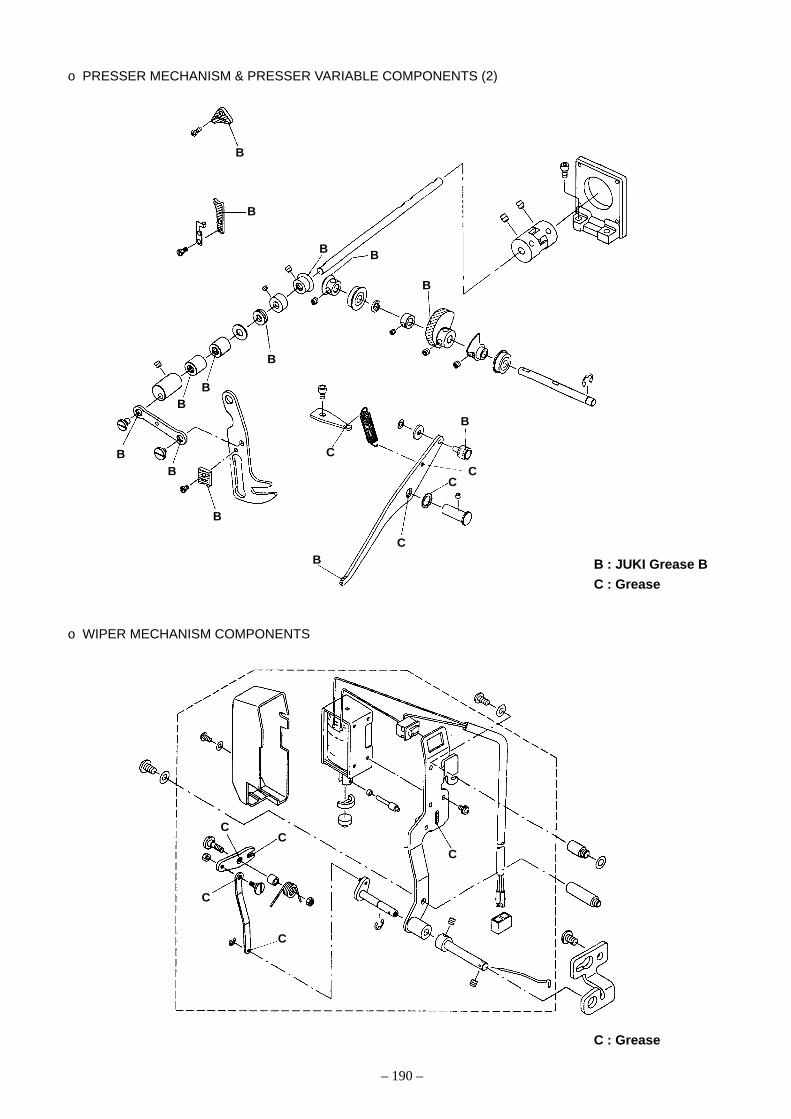
– 190 –
o PRESSER MECHANISM & PRESSER VARIABLE COMPONENTS (2)
o WIPER MECHANISM COMPONENTS
B
B
B B
B
BB
B
BB
B
C
B
C
CB
C
CC
C
C
C
C : Grease
B : JUKI Grease B
C : Grease

– 191 –
o PRESSER PLATE & MANUAL PRESSER MECHANISM COMPONENTS
o TENSION RELESASE & THREAD TENSION COMPONENTS
A
A
C
B
B
C
A
CC
B
BB
B
B
B
C
C
C
B
C
C
C
C
C
C
A : JUKI Grease A
B : JUKI Grease B
C : Grease
C : Grease

– 192 –
o SHUTTLE DRIVER SHAFT COMPONENTS
o FRAME & MISCELLANEOUS COVER COMPONENTS (2)
A
A
A
A
A
A : JUKI Grease A
A : JUKI Grease A

– 193 –
o TENSION RELEASE & THREAD TRIMMER MECHANISM COMPONENTS
o THREAD CLAMP COMPONENTS
A
A
A
A
C
CC
C
C
C
C C
C
A : JUKI Grease A
C : Grease
C : Grease
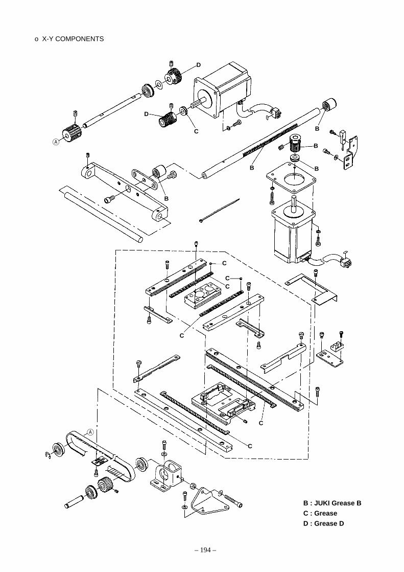
– 194 –
o X-Y COMPONENTS
D
D
C
A
B
B
B
B
B
C
CC
C
C
C
A
B : JUKI Grease B
C : Grease
D : Grease D

– 195 –
o CLOTH FEED MECHANISM COMPONENTS (FOR AMS-210EHS, ESS)
o CLOTH FEED MECHANISM COMPONENTS (FOR AMS-210EHL, ESL)
C
C
C
C
C
BC
CC
CC
C
C
CC
B
C
C
C
C
B : JUKI Grease B
C : Grease
B : JUKI Grease B
C : Grease

– 196 –
(5) Replenishing the designated places with grease* Perform grease supplement when the errors below are displayed or once a year (either one which is
earlier). After performing grease supplement, call memory switch No. 245 and set the value to ì0îwith the reset key.
When the sewing machine has been used for a certain number or times of sewing, error code No. E220 isdisplayed on the operation panel at the time of turning ON the power. This display informs the operator of thetime of replenishing the designated places with grease. Be sure to replenish the places with the grease below.Then call the memory switch No. 245 and set it to ì0î with the RESET key.Even after the display of the error No. E220, when the RESET key is pressed, the error is released, and thesewing machine can be continuously used. Afterwards, however, the error No. E220 is displayed every timethe power is turned ON.In addition, when the sewing machine is used further for a certain period of time after the display of error No.E220, the error No. E221 is displayed and the sewing machine fails to operate since the error cannot bereleased even when the RESET key is pressed.When the error No. E221 is displayed, be sure to replenish the designated places below with grease.Then start up the memory switch and set No. 245 to “0” with the RESET key.
(Caution) 1. After replenishing the places with grease, the error No. E220 or No. E221 is displayedagain unless the memory switch No. 245 is changed to “0”.
2. Use grease tube (JUKI grease B Part No. : 40013640) supplied as accessories to replen-ish the designated places below with grease. If grease other than the designated one isreplenished, damage of components will be caused.
1. Open the upside cover and remove the JUKIgrease B .
2. Remove rubber cap located on the side of eccen-tric cam . Then replenish there with JUKI greaseB .
1) Replenishing the eccentric cam section with grease
WARNING:Turn OFF the power before starting the work so as to prevent accidents caused by abrupt startof the sewing machine.

– 197 –
1. Tilt the machine head and remove the grease cover.
2. Fill joint supplied as an accessory with JUKIGrease B.
3. Remove setscrew in oscillator gear and screwin joint into the screw hole.
4. Screw in screw supplied as accessories to thejoint and replenish there with JUKI grease B.
5. Securely tighten setscrew which has been re-moved after replenishing with the grease.
2) Replenishing the oscillator pin section with grease
1. Open the face plate cover.2. Supplement JUKI grease B to the felt section (3
places) and the hinge screws around them.
3) Grease supplement to the face plate section
1. At the same time, apply JUKI grease B to the rearfaces of X guide shaft and presser plate .
4) Grease supplement to X guide shaft bearing

– 198 –
11. Error code listError code Pict Description of error How to recover Place of recovery
E001 Data is initializes Turn OFF(EEPROM of MAIN CPU) the power
E007 Main shaft motor-lock Turn OFFWhen large needle resistance sewing product is sewn the power
E008 Head connector abnormality Turn OFFMemory of machine head cannot be read. the power
E010 Pattern No. error Possible to PreviousPattern No. which is backed up is not registered to re-enter after screendata ROM,or setting of reading inoperative is reset.performed.
E011 External media not inserted Possible to PreviousExternal media is not inserted. re-enter after screen
reset.
E012 Read error Possible to PreviousData read from external media cannot be performed. re-start after screen
reset.
E013 Write error Possible to PreviousData write from external media cannot be performed. re-start after screen
reset.
E014 Write protect Possible to PreviousExternal media is in the write prohibition state re-start after screen
reset.
E015 Format error Possible to PreviousFormat cannot be performed. re-start after screen
reset.
E016 External media capacity over Possible to PreviousCapacity of external media is short. re-start after screen
reset.

– 199 –
Error code Pict Description of error How to recover Place of recovery
E017 EEP-ROM capacity over Possible to PreviousWhen the mounted EEP-ROM is different in type. re-start after screen
reset.
E018 Type of EEP-ROM is different. PreviousWhen the mounted EEP-ROM is different in type. screen
E019 File size over Possible to PreviousPattern data size over re-start after screen
reset.
E022 File No. error Possible to PreviousThere is no designated file in the server or external re-start after screenmedia. reset.
E024 Pattern data size over Possible to Data inputWhen sewing cannot be performed since the size re-start after screenof downloaded sewing data is too large. reset.
E027 Read error Possible to PreviousData read from server cannot be performed. re-start after screen
reset.
E028 Write error Possible to PreviousData write to the server cannot be performed. re-start after screen
reset.
E029 Smart media slot release error Possible to PreviousLid of smart media slot is open. re-start after screen
reset.
E030 Needle bar upper position failure Turn hand Data inputTurn hand pulley to bring needle bar to its UP pulley to screenposition bring needle
bar to its UPposition.
E031 Air pressure drop Possible to Data inputWhen the air pressure is lowered. re-start after screen
reset.

– 200 –
Error code Pict Description of error How to recover Place of recovery
E032 File interchanging error Possible to Data inputFile cannot be read. re-start after screen
reset.
E040 Sewing area over Possible to SewingWhen the sewing area is exceeded re-start after screen
reset.
E042 Operation cannot be performed. Possible to Previousre-start after screenreset.
E043 Enlarging error Possible to Data inputSewing pitch exceeds Max. pitch. re-start after screen
reset.
E045 Pattern data error Possible to Data inputThese pattern data are not applicable. re-start after screen
reset.
E050 Stop switch Possible to StepWhen stop switch is pressed during machine re-start after screenrunning. reset.
E052 Thread breakage detection error Possible to StepWhen thread breakage is detected. re-start after screen
reset.
E061 Memory switch data error Turn OFFMemory switch data is broken or revision is old. the power.
E063 Head discrimination error Turn OFFHead discrimination and the kind of control box the power.are different.
E220 Grease-up warning Possible to Data inputAt the time of operation of 100 million stitches re-start after screen→ Refer to “10.-(5) Replenishing the designated reset.places with grease”.
E221 Grease-up error Possible to Data inputAt he time of operation of 120 million stitches re-start after screenThe sewing machine is put in the sewing-impossible status. reset.It is possible to clear with memory switch .→ Refer to “10.-(5) Replenishing the designatedplaces with grease”.

– 201 –
Error code Pict Description of error How to recover Place of recovery
E302 Confirmation of tilt of machine head Possible to PreviousWhen tilt of machine head sensor is OFF. re-start after screen
reset.
E303 Phase Z detection error Turn OFFDetection of the upper dead point is impossible for the power.the sewing machine.
E305 Thread trimmer knife position error Turn OFF Data inputThe thread trimmer knife is not in the regular position. the power. screen
E306 Thread clamp position error Turn OFFThread clamp unit is not in the regular position. the power
E307 External input command time out error Possible to Data inputInput is not performed for a fixed period of time with re-start after screenthe external input command of vector data. reset.
E308 Time-out error of wait terminal Turn OFFThere is no input to wait terminal for a certain period the powerof time.
E431 Outer presser is rising. Possible to Previousre-start after screenreset.
E432 Proper operation has not been performed. Possible to Previousre-start after screenreset.
E433 Number of stitches has exceeded the limit. Possible to Previousre-start after screenreset.
E434 Hadware error has occurred. Possible to Previousre-start after screenreset.
E437 Function cannot be selected. Possible to Previousre-start after screenreset.

– 202 –
Error code Pict Description of error How to recover Place of recovery
E438 Execution cannot be performed. Possible to Previousre-start after screenreset.
E441 Back-up data does not exist. Possible to Previousre-start after screenreset.
E703 Panel is connected to the machine other than Possible to Commnunicationsupposed. (Machine type error) rewrite program screenWhen machine type code of system is improper in after pressingcase of initial communication. down
communicationswitch.
E704 Inconsistency of system version Possible to CommnunicationWhen version of system software is improper in rewrite program screencase of initial communication. down
communicationswitch.
E730 Main shaft motor encoder defectiveness or Turn OFFphase-out the powerWhen encoder of sewing machine motor isabnormal.
E731 Main motor hole sensor defectiveness or Turn OFFposition sensor defectiveness the power.When hole sensor or position sensor of sewingmachine is defective.
E733 Reverse rotation of main shaft motor Turn OFFWhen sewing machine motor rotates in reverse the power.direction.
E802 Power instantaneous cut detection Turn OFFWhen input power is instantaneously OFF. the power.
E811 Over voltage Turn OFF
When input power is more than the specified value. the power.
E813 Low voltage Turn OFFWhen input voltage is 150V or less. the power.
E901 Abnormality of main shaft motor IPM Turn OFFWhen IPM of servo control p.c.b. is abnormal. the power.

– 203 –
Error code Pict Description of error How to recover Place of recovery
E903 Abnormality of stepping motor power Turn OFFWhen stepping motor power of servo control p.c.b. the power.fluctuates ±15% or more.
E904 Abnormality of solenoid power Turn OFFWhen solenoid power of servo control p.c.b. the power.fluctuates ±15% or more.
E905 Heat sink temperature for SERVO CONTROL p.c.b. Turn OFFfabnormality the power.Turn ON the power again after taking overheat timeof SERVO CONTROL p.c.b.
E907 X feed motor origin retrieval error Turn OFFWhen origin sensor signal is not inputted at the time the power.of origin retrieval motion.
E908 Y-feed motor origin retrieval error Turn OFFWhen origin sensor signal is not inputted at the the power.time of origin retrieval motion.
E910 Presser motor origin retrieval error Turn OFFWhen origin sensor signal is not inputted at the the power.time of origin retrieval motion.
E913 Thread clamp origin retrieval error Turn OFFWhen origin sensor signal is not inputted at the time the power. of origin retrieval motion.
E914 Feed defective error Turn OFFTiming lag between feed and main shaft occurs. the power.
E915 Abnormality of communication between Turn OFFoperation panel and main CPU the power.When abnormality occurs in data communication.
E916 Abnormality of communication between main Turn OFFCPU and main shaft CPU the power.When abnormality occurs in data communication.
E917 Failure of communication between operation Possible topanel and personal computer re-start afterWhen abnormality occurs in data communication. reset.

– 204 –
Error code Pict Description of error How to recover Place of recovery
E918 MAIN board overheat Turn OFFOverheat of MAIN board the power.Turn ON the power again after taking time.
E925 Intermediate presser motor origin retrieval error Turn OFFOrigin sensor of intermediate presser motor does not the power.change at the time of origin retrieval.
E943 MAIN EEP-ROM trouble Turn OFFWhen data writing to EEP-ROM cannot be the power.performed.
E946 Defective EEP-ROM writing of HEAD RELAY board Turn OFFWhen data writing to EEP-ROM cannot be performed. the power.
E948 F-ROM abnormality Turn OFFWhen erase or writing of program cannot be the power.performed at the time of downloading program.

– 205 –
12. Message list
Message No. Display Display message Description
M520 Erase confirmation of User’s pattern
Erase is performed. OK?
M521 Erase confirmation of pattern button
Erase is performed. OK?
M522 Erase confirmation cycle pattern
Erase is performed. OK?
M523 Erase confirmation of backup data
Pattern data is not stored in memory.
Erase is OK?
M528 Overwriting confirmation of users’
pattern
Overwriting is performed. OK?
M529 Overwriting confirmation of smart
media
Overwriting is performed. OK?
M530 Overwriting confirmation of vector
data of panel/M3 data/sewing
standard format data/simplified
program data
Overwriting is performed. OK?
M531 Overwriting confirmation of vector
data of smart media/M3 data/
sewingstandard format data/
simplified program data
Overwriting is performed. OK?

– 206 –
Message No. Display Display message Description
M532 Overwriting confirmation of vector
data on personal computer/M3
data/sewingstandard format data/
simplified program data
Overwriting is performed. OK?
M534 Overwriting confirmation of
adjustment data of smart media
and all machine data
Overwriting is performed. OK?
M535 Overwriting confirmation of
adjustment data on personal
computer and all machine data
Overwriting is performed. OK?
M537 Delection confirmation of thread
tension command
Delecting is performed. OK?
M538 Delection confirmation of
intermediate presser increase/
decrease value
Delecting is performed. OK?
M542 Format confirmation
Formatting is performed. OK?
M544 Data corresponding to panel does
not exist.
Data does not exist.
M545 Data corresponding to smart
media does not exist.
Data does not exist.

Message No. Display Display message Description
M546 Data corresponding to personal
computer does not exist.
Data does not exist.
M547 Overwriting prohibition on pattern
data
Overwriting cannot be performed
since data exists.
M548 Overwriting prohibition on smart
media data
Overwriting cannot be performed
since data exists.
M549 Overwriting prohibition on data on
personal computer
Overwriting cannot be performed
since data exists.
M550 Backup data information on main
body input
There is back-up data of body input.
M653 During formatting
Formatting is performed.
M669 During data reading
Data is being read.
M670 During data writing
Data is being written.
M671 During data converting
Data is being converted.
– 207 –

– 208 –
1.Sewing machine locked 1-1)Large needle compared with Replace the needle hole guide.the hole diameter of the needlehole guide
2.Deformation in sewn patterns 2-1) X timing belt tension is Adjust the X timing belt tension.maladjusted.
2-2)Backlash of the X feed motor Adjust the position of X feed motor.gear is maladjusted.
2-3)Backlash of the Y feed motor Adjust the position of Y feed motor.gear is maladjusted.
2-4)Traveling torque in X direction 4-A) Pressure of the X-Y table is Adjust the pressure of the X-Y table.or Y direction is excessive. too high.
4-B) Height or horizontality is Adjust the height or the horizontality of the needleinadequate for the needle bar bar auxiliary cover.auxiliary cover.
2-5)Pressing pressure is too low. 5-A)Regulator is maladjusted. Adjust the regulator.(Air specification)
5-B) Supply air pressure is too low. Adjust the supply air pressure.
3.There is no coincidence between 3-1) Inadequate adjustment of the Adjust the position of X origin sensor. the input origin and the sewing origin. X origin sensor
3-2) Inadequate adjustment of the Adjust the position of Y origin sensor.Y origin sensor
4 Feeding action does not stop even 4-1) Inadequate adjustment of the Adjust the position of X origin sensor.after exceeding the sewing range. X origin sensor
4-2) Inadequate adjustment of the Adjust the position of Y origin sensor.Y origin sensor
5.The amount of lifting is small for the 5-1) Inadequate adjustment of the Adjust the height of the presser.outer frame of the cloth presser. height of the presser
Trouble Cause (1) Cause (2) Check and corrective measures
13. Troubles and corrective measures(1) Mechanical parts

– 209 –
6.The outer frame of the cloth presser 6-1)The thread trimmer cam Decide the position of the thread trimmer cam screwcannot be lifted or lowered. screw is loose. and fix it.
(Motor specification only)
6-2)Presser pulse motor malfunction 2-A) The presser pulse motor is Replace the presser pulse motor.(motor specifications only) out of order.
2-B) Connection of presser pulse Check the connector connections.motor is improper.
6-3)Defective board 3-A) The board is out of order. Replace the board.
3-B) Connector connections are Check the connector connections.improper.
6-4)There are inadequate fitting Examine the positions for greasing.conditions among the work feedbar, the link, and the face plate. The sewing material is not pressed completely by the
outer frame as a whole.
6-5)Supply air pressure is too low. Adjust the supply air pressure.(Air specification only)
6-6) Inadequate adjustment of the Adjust the regulator.regulator (air specifications only)
6-7)Solenoid valve malfunction Reolace the solenoid valve.(air specifications only
6-8) Inadequate adjustment of the Adjust the speed controller.speed controller(air specifications only)
7.The intermediate presser does not 7-1)There are some inadequate Check for the inadequate fitting and rattling conditionsrise after sewing. fitting conditions in the intermedi in the link mechanism.
ate presser link mechanism. Examine the positions for greasing.
7-2) Intermediate presser variable Adjust the intermediate presser variable.is maladjusted.
7-3) Intermediate presser pulse 3-A) Intermediate presser pulse Replace the intermediate presser pulse motor.motor malfunction motor is out of order.
3-B) Connection of intermediate Check the connector connections.presser pulse motor isimproper.
7-4)Defective board 4-A) The board is out of order. Replace the board.
4-B) Connector connections are Check the connector connections.improper.
Trouble Cause (1) Cause (2) Check and corrective measures

– 210 –
8.The intermediate presser does not 8-1)There are some inadequate Check for the inadequate fitting and rattling conditionswork during sewing. fitting conditions in the inter- in the link mechanism.
mediate presser link mechanism. Examine the positions for greasing.
8-2) Intermediate presser variable Intermediate presser variable adjustments.is maladjusted.
8-3) Intermediate presser pulse 3-A) Intermediate presser pulse Replace the intermediate presser pulse motor.motor malfunction motor is out of order.
3-B) Connection of intermediate Check the connector connections.presser pulse motor is improper.
8-4)Defective board 4-A) The board is out of order. Replace the board.
4-B) Connector connections are Check the connector connections.improper.
8-5)The intermediate presser Adjust the intermediate presser variable stroke.stroke has decreased to 0mm.
9.Unusual sound is generated from 9-1)The clearance is too much Adjust the clearance between the inner hook and thethe face section. between the inner hook and driver.
the driver.
9-2)The intermediate presser bar Adjust the intermediate presser adjusting arm.connection comes in contactwith the lower metal of theintermediate presser needle bar.
9-3)The intermediate presser comes 3-A) Inadequate adjustment of the Adjust the height of the intermediate presser.in contact with the throat plate. height of the intermediate presser
9-4)The intermediate presser comes Adjust the presser.in contact with the cloth presser.
9-5) Intermediate presser variable Intermediate presser variable adjustments.is maladjusted.
9-6) Intermediate presser pulse 6-A) Intermediate presser pulse Replace the intermediate presser pulse motor.motor malfunction motor is out of order.
6-B) Connection of intermediate Check the connector connections.presser pulse motor is improper.
9-7)Defective board 7-A) The board is out of order. Replace the board.
7-B) Connector connections are Check the connector connections.improper.
Trouble Cause (1) Cause (2) Check and corrective measures

– 211 –
10. Even when the sewing machine is 10-1) The needle thread is not Pass the needle thread.started, it goes to stop soon. hooked.
10-2) Position of the thread breakage Adjust the position of the thread breakage detectingdetecting plate is wrong. plate.
11. Even though the needle thread is 11-1) Position of the thread Adjust the position of the thread breakage detectingbroken, the sewing machine does breakage detecting plate is plate.not stop. wrong.
12. Wiper cannot spread a thread 12-1) Interference between wiper 1-A) Wiper mounting position is Adjust the wiper position.and needle inadequate.
12-2) Interference between wiper 2-A) Inadequate adjustment of the Adjust the height of the intermediate presser.and intermediate presser height of the intermediate
presser
2-B) Wiper mounting position is Adjust the wiper position.inadequate.
12-3) There is no clearance between 3-A) The cloth thickness permitting Use the lower wipe-out sequence.the needle and intermediate the use of a wiper is exceeded.presser to pass the wiper.
12-4) The wiper does not move 4-A) The wiper switch is turned Turn the wiper switch ON.after thread trimming. OFF.
13. Severe vibration 13-1) Position of the crank balancer Define the correct crank balancer position.is wrong.
Trouble Cause (1) Cause (2) Check and corrective measures

– 212 –
1. Thread comes off at the start of 1-1) Stitch skipping at the start of 1-A) Too much clearance between Set the clearance at 0.05 to 0.1mm between the needle and the hook. sewing sewing needle and hook.
Set up “soft start” at the beginning of sewing.
1-B) Penetration registance of the Use a thinner needle. (Lower the needle count to bethread against the cloth is small. used.)
1-2) Length of thread remaining 2-A) Tension controller No. 1 provides Properly adjust the tension controller No. 1.at the needle is not sufficient. an excessive tension.
2-B) Floating of the AT thread Adjust the amount of AT thread tension floating.tension disc is insufficient.
2-C)Stroke of the thread take-up Adjust the stroke of the thread take-up spring.spring is excessive.
2-D)The thread take-up spring Adjust the thread take-up spring tension.tension is insufficient.
2-E) Level difference between the Adjust the height of the counter knife.needle hole guide and thecounter knife is excessively high.
2-F) Needle thread tension is high Adjust the needle thread tension.and the thread is excessivelystretched.
2-G)Thread spreading section of Polish the thread spreading section of the movingthe moving knife has scratches. knife with buff or replace the knife.
1-3)Length of bobbin thread re- 3-A) Level difference between the Adjust the height of the counter knife.maining is not sufficient. needle hole guide and the (Otherwise, widen the gap.)
counter knife is excessively high.
3-B) Lower face of the needle hole Polish the needle hole guide with a buff or replace it.guide has scratches.
3-C)Thread spreading section of the Polish the thread spreading section of the movingmoving knife has scratches. knife with buff or replace the knife.
3-D)Shuttle upper spring has Polish the shuttle upper race with a buff or replacescratches. it.
3-E) The bobbin thread tension is Adjust the bobbin thread tension.excessive.
3-F) The bobbin or bobbin case Polish it with a buff or replace it.has scratches.
Trouble Cause (1) Cause (2) Check and corrective measures
(2) Sewing conditions
To the next page

– 213 –
1-4)Material to be sewn is not Remove the slack of the material to be sewn.properly stretched.
1-5)Unstable needle thread clamp 5-A) Thread tends to be extended Increase the needle thread clamp needle number toor sliding efficiency is worse. 3~4 stitches.
Lower the speed of the first stitch. (600 ~ 1000rpm)
5-B) Pitch of the first stitch is too small. Lower the needle thread tension of the first stitch.
Increase the pitch of the first stitch.
1-6)Threading the needle bar Refer to the item “Threading the needle bar threadthread guide is wrong. Guide”.
1-7)Bobbin runs idle and the bobbin Use a stronger idling prevention spring.thread is drawn out.
7-A) Initial positioning of the mov- Adjust the initial position of the moving knife.ing knife is inadequate.
2. Needle breakage 2-1) Inadequate clearance between Adjust the clearance between needle and shuttle driver.the shuttle driver and theneedle
2-2) Inadequate clearance between Adjust the clearance between the needle and thethe needle and the inner hook. inner hook.
2-3) Feed timing is defective 3-A) Too late feed timing for cloth Change the feed timing by the use of the memory switch.thickness
2-4)Needle coming in contact Adjust the moving knife position.with the moving knife
2-5)Needle coming in contact Adjust the wiper position.with the wiper
2-6)Needle is bent 6-A) The needle thread tension is Adjust the tension to a proper level.too high.
2-7) Needle is too thin. Change the needle No. to the suitable one to the material.
2-8) Interference between work Adjust the work clamp foot (feed bracket) position.clamp foot and needle
From the previous page
Trouble Cause (1) Cause (2) Check and corrective measures

– 214 –
3. Stitch Skipping 3-1)Too much clearance between Adjust the clearance between needle and inner hook.the needle and the inner hook.
3-2) Inadequate timing adjustment Adjust timing for the needle and the inner hook.for the needle and the inner hook.
3-3) Inadequate clearance between Adjust the clearance between needle and shuttle driver.the shuttle driver and the needle
3-4)Material to be sewn is not 4-A) Too much clearance between Adjust the work clamp foot height.properly stretched. the work clamp foot and
sewing object Remove the slackness of the sewing object.
3-5)Needle is bent or blunt. Replace the needle.
3-6)Loop of the needle thread Attach the needle with the long groove orienting slightlyfalls down. to the right. (Approximately 20°)
6-A) Feed timing is too fast. Change the feed timing by the use of the memory switch.
4. Needle thread breakage 4-1)Stratches on the inner hook 1-A) Scratches on section A After polishing the blade point of the inner hook with(Contact of the inner hook with oilstone, polish it with polishing powder. Properly adjustthe needle) the clearance between the needle and the inner hook.
1-B) Scratches on section B After polishing the blade point of the inner hook, polish it(Scratches occur when the with polishing powder.needle is bent or broken.)
1-C)Scratches on section C After polishing the blade point of the inner hook, polish it(Needle scratches the inner hook with polishing powder.when removing the inner hook.)
1-D)Scratches on section D After polishing the blade point of the inner hook, polish itwith polishing powder.
4-2)Thread enters into the shuttle. 2-A) Position of the shuttle upper Properly adjust the position of the shuttle upperspring is wrong. spring.
2-B) Blade point section A of the Replace the inner hook.shuttle is round.
2-C)Position of the shuttle is wrong. Properly adjust the position od the shuttle.
2-D)Needle thread tension is too low. Properly adjust the needle thread tension.
Trouble Cause (1) Cause (2) Check and corrective measures
A
To the next page To the next page
A
BC
D

– 215 –
2-E) Thread take-up spring tension Adjust the thread take-up spring.is too low.
2-F) Length of the remaining Properly adjust the tension controller No. 1.needle thread is too long.
2-G)The specified inner hook and Use the specified parts.shuttle driver are not used.
4-3) Scratches on the shuttle driver. Remove the scratches and polish with buff, or replacethe shuttle driver.
4-4)Clearance between the shuttle Properly adjust the clearance between the shuttledriver and the inner hook is too small. driver and the inner hook.
4-5)Scratches on the needle hole Remove the scratches and polish with buff, or replaceguide. the needle hole guide.
4-6)Finish of the needle hole is rough. Replace the needle.
4-7)Thread take-up spring is 7-A) Stroke of the thread take-up Properly adjust the thread take-up spring.maladjusted. spring is too large.
7-B) Thread take-up spring tension Properly adjust the thread take-up spring.is too high.
4-8)Rotation of the inner hook is 8-A) Race face of the shuttle is Remove the inner hook and remove the thread waste.defective. clogged with thread waste.
8-B) Oil amount is insufficient. Supply oil to the shuttle components.
4-9)Needle thread clamp device 9-A) Needle thread length is Adjust the needle thread length and turn the needleOFF inadequate. thread clamp device ON.
4-10) Chemical fiber thread is Use of silicone oil melted with heat from the
needle. Use of needle coated with fluoro carbon resin
Trouble Cause (1) Cause (2) Check and corrective measures
From the previous page From the previous page

– 216 –
5. Thread breakage at the time of 5-1)Thread release timing is 1-A) Floating of the AT thread tension Adjust the amount of AT thread tension floating. thread trimming. defective. disk is insufficient.
5-2)Thread spreading section of the Paying attention to the blade section, polish withmoving knife has scratches. polishing powder.
5-3)Shuttle upper spring has Remove the scratches.scratches.
5-4)Level difference between the 4-A) Thread is cut before trimming Properly adjust the position of counter knife.needle hole guide and the with the blade section of thecounter knife is too high. moving knife.
5-5)Clearance between the needle 5-A) Thread is cut before trimming Properly adjust the position of counter knife.hole guide and the counter with the blade section of theknife is too small. moving knife.
5-6)Lower face of the needle hole 6-A) Thread is cut with the needle Remove the scratches and polish with buff, or replaceguide has scratches. hole guide. the needle hole guide.
5-7)Thread spreading timing of Adjust initial positions of the presser origin sensor,the moving knife is defective. thread trimmer, and the moving knife.
5-8)Thread take-up spring tension Adjust the thread take-up spring.is too low.
5-9)Scratched bobbin thread Eliminate the scratch.holder
Trouble Cause (1) Cause (2) Check and corrective measures

– 217 –
6. Defective thread trimming 6-1) Sharpness of the knife is 1-A) Abrasion of moving and Replace the moving and counter knives.difective counter knives.
1-B) Engagement of the moving Properly adjust the heigh and position of the movingand counter knives is defective. and counter knives.
1-C)Parallel of the blade section Properly adjust the parallel of the blade section ofof counter knife is defective. counter knife.
1-D)Attaching position of the Properly adjust the attaching position of counter knife.counter knife is defective.
6-2)Double cutting for the needle 2-A) There is a burr on thread spreading Paying attention to the blade section, polish withthread. (Thread waste remains section A of the moving knife. polishing power, or replace the moving knife.inside the cylinder arm cap.) The shape of the thread
trimmed becomes andthread waste remains.
2-B) Shuttle upper spring has scratches. Remove the scratches.(The shape of the thread trimmedbecomes and thread wasteremains.)
6-3)Moving knife does not spread 3-A) Initial position of the moving Adjust the initial position of the moving knife.threads. knife is maladjusted.
3-B) Thread trimmer cam position Adjust the thread trimmer cam position.is inadequate.
3-C)Position of the shuttle upper Adjust the position of shuttle upper spring .spring is defective.
6-4)Stitch skipping at the final stitch 4-A) Timing of the needle to the Adjust the timing and the clearance.inner hook and the clearancebetween them are defective.
4-B) Work clamp foot big. Let the biginning of stitch come closer to the presserby moving the pattern.
4-C)Loop of the needle thread Attach the needle with the long groove orientingfalls down. slightly to the right (approximately 20°)
6-5)Bobbin thread cannot be cut. 5-A) Bobbin thread tension is low. Streng then the bobbin thread tension.
5-B) Needle hole size of the needle Replace the needle hole guide with a new one havinghole guide is large. a smaller hole diameter.
Trouble Cause (1) Cause (2) Check and corrective measures
A
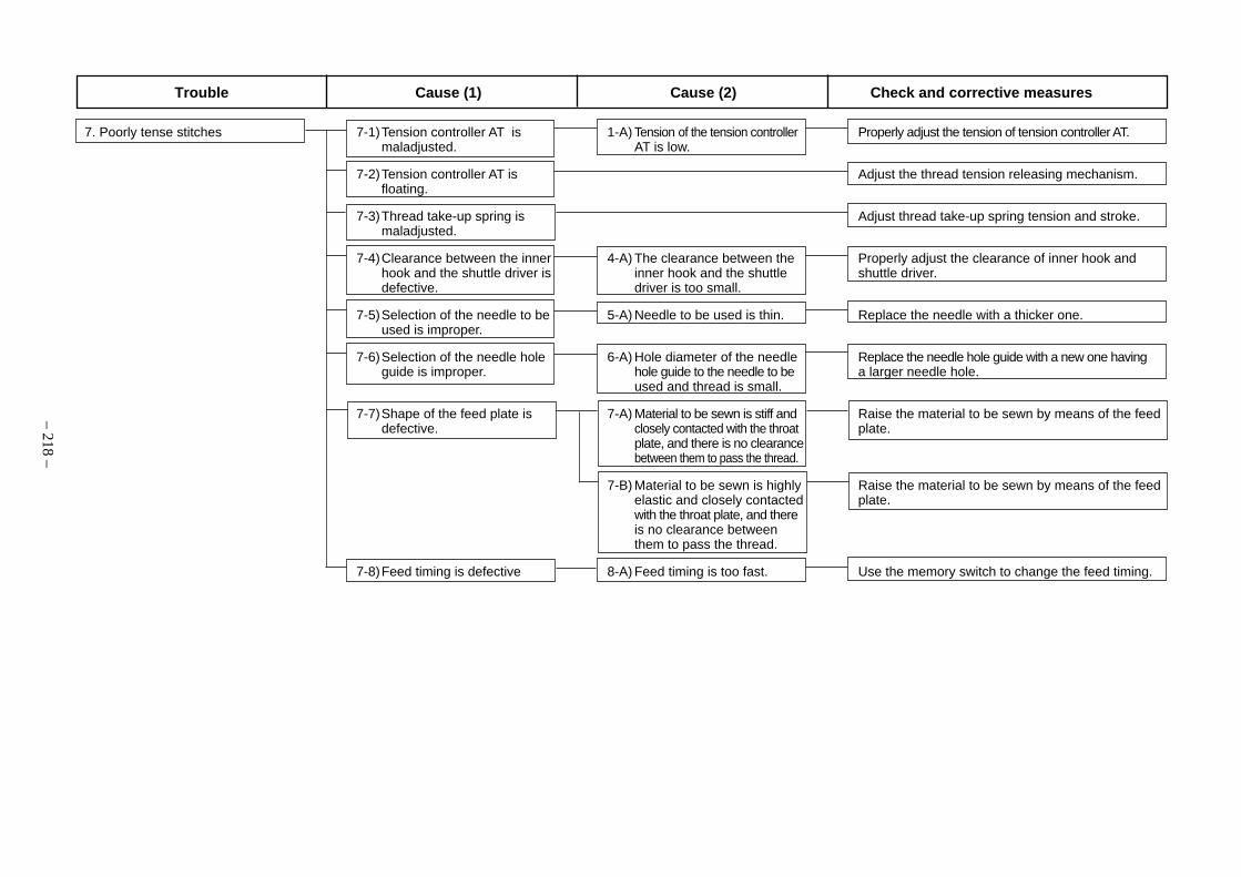
– 218 –
7. Poorly tense stitches 7-1)Tension controller AT is 1-A) Tension of the tension controller Properly adjust the tension of tension controller AT.maladjusted. AT is low.
7-2)Tension controller AT is Adjust the thread tension releasing mechanism.floating.
7-3)Thread take-up spring is Adjust thread take-up spring tension and stroke.maladjusted.
7-4)Clearance between the inner 4-A) The clearance between the Properly adjust the clearance of inner hook andhook and the shuttle driver is inner hook and the shuttle shuttle driver.defective. driver is too small.
7-5)Selection of the needle to be 5-A) Needle to be used is thin. Replace the needle with a thicker one.used is improper.
7-6)Selection of the needle hole 6-A) Hole diameter of the needle Replace the needle hole guide with a new one havingguide is improper. hole guide to the needle to be a larger needle hole.
used and thread is small.
7-7)Shape of the feed plate is 7-A) Material to be sewn is stiff and Raise the material to be sewn by means of the feeddefective. closely contacted with the throat plate.
plate, and there is no clearancebetween them to pass the thread.
7-B) Material to be sewn is highly Raise the material to be sewn by means of the feedelastic and closely contacted plate.with the throat plate, and thereis no clearance betweenthem to pass the thread.
7-8)Feed timing is defective 8-A) Feed timing is too fast. Use the memory switch to change the feed timing.
Trouble Cause (1) Cause (2) Check and corrective measures

– 219 –
8. Defective stitches with the synthetic 8-1)Thread breakage due to heat 1-A) The sewing speed is too fast. Slow down the maximum speed. thread
1-B) The needle used is too thick. Use a thin needle or a super needle for the syntheticthread.
Use silicon.
Use a needle cooler.
8-2)Thread makes burrs. 2-A) Thread path is defective. Polish the thread path of each component with polishing powder.
2-B) Finish of the needle hole is defective. Replace the needle.
2-C)Loop of the needle thread falls down. Move the machine arm thread guide A to the left.
8-3)Thread floating occurs at the 3-A) Penetration registance of the Use a thinner needle. (Lower the number of needle to be used.)sewing start. thread against the cloth is too
small. Needle thread clamp device ON.
8-4)Stitch skipping due to the heat. 4-A) Sewing speed is too fast. Change the maximum speed (electrical components.)
4-B) Needle is too thin. Use a thicker needle. (Raise the number of needle to be used.)
4-C)Loop of the needle thread falls down. Attach the needle with the long groove orienting slightlyto the right (approximately 20°).
8-5)Uneven stitch tightness due 5-A) Sewing speed is too fast. Reduce the speed by means of the speed variable resistor.to the stretch of thread.
5-B) Tension of the tension controller Decrease the tension of tension controller AT.AT is excessive.
9. Thread chips generated in the 9-1)Long needle thread at the 1-A) The thread trimmer is used Needle thread clamp device OFF shuttle beginning of stitches for cutting.
Adjust the needle thread length to 32 ~ 36mm
Increase the sewing length to more than 10mm.
Trouble Cause (1) Cause (2) Check and corrective measures

– 220 –
1. No display at the operation panel. 1-1)DC power (+5 V, +24V) is not 1-A) AC power is not supplied. Examine if a power supply is available at the powersupplied. switch.
1-B) The FLT board has no power Check whether an AC voltage is available betweensupply. Pins 4-5 of CN1 in the FLT board. If no voltage is found,
check the connections around the power switch or thepower plug.
1-C)The SDC board has no power Check the connection of CN1 of SDC board.supply. (The power supply isis available so long as LED4 Check the connection between CN17 of the SDC board of the SDC board is lit.) and CN2 of the FLT board.
Confirm that the inrush protection resistor is normal inthe FLT board.FLT-T board R2, R3FLT-S board R1
1-D)The MAIN board has no power Check the CN31 power supply of the MAIN board.supply. 1, 2: +48V
3: +24V4: +5V5: +33V6, 7, 8: GNDCheck the output voltage in the SDC board unit.Check if there is shortcircuiting in the 5V powersystem for the MAIN board.
1-E) The operation panel has no Check if there is shortcircuiting in the +5V powerpower supply. system for the operation panel.
Check the connection between CN34 of the MAINboard and the panel.
1-2)Detection of a momentary 2-A) No momentary interruption Check the connection between CN3 of the FLT boardinterruption in the SDC board sensor signal input is entered and CN13 of the SDC board.LED3 on SDC board: in the SDC board.Flashing 9 times
2-B) No AC voltage is available When a sewing machine for 3-phase specificationsbetween Pins 4-5 of CN1 in is used in a 1-phase system, connect the powerthe FLT board. (In case of supply to black and white of the power cord led fromFLT-T board) the box.
Trouble Cause (1) Cause (2) Check and corrective measures
(3) Electrical components (Refer to “13.-(1) Block diagram A” as well.)

– 221 –
2.Key malfunction on the operation 2-1) IP-400 : There is no signal 1-A) Connector connection defective Check the connection between the touch panel andpanel from the touch panel. CN109 of the Panel board.It does not function so effectively.
1-B) The switch position of the Start the Check Program 1_01 and readjust the switchtouch panel is displaced. position.
1-C)Touch panel fault Replacement of the LCD assembly (40034529)
2-2)CP-20: The Panel CPU does 2-A) The circuit is out of order. Replace the PANEL board (40031471).not accept the key.
3.Error E007 3-1)The main shaft motor of the 1-A) No power is fed to the motor. Check the connection of CN16 of SDC board.Machine lock sewing machine cannot rotate.LED3 on SDC board: Flashing 1 times
1-B) The mechanism is locked. Turn it by hand in the state that the power supplyis turned OFF. Confirm whether the upper shaft islocked. If there is any abnormality, remove it.
1-C)The driver circuit is out of order. Replace the SDC board.
1-D)The motor is out of order. Measure the resistance of the motor winding. If thereis any abnormality, replace the motor.
4.Error E029 4-1)The switch signal is not received. 1-A) The slot OPEN-OFF switch Check the cover to examine whether the switch pinSmart media slot open error is not pressed. can be pressed.
If there is any abnormality, replace the cover.
Confirm the switch pin whether it is normal.If there is any abnormality, replace the board.
5.Error E030 5-1) It cannot stop in upper position. 1-A) The servo lock is not effective. Turn it by hand in the state that the power supply isNeedle bar upper position turned OFF. Confirm if there are large variations indisplacement the load.
Replace the SDC board.
6.Error E031 6-1)The air sensor switch is not 1-A) Air pressure variation or drop Check the air pressure and the air source.Air pressure drop turned ON.
Check the pressure setup value of the air sensor(0.34MPa)
1-B) Switch defective Check the air switch by means of a circuit tester.
Connector check MAIN board CN52
Trouble Cause (1) Cause (2) Check and corrective measures

– 222 –
7. Error E050 7-1)The switch contact point is 1-A) Connector connection defective Check CN69 of INT board.Temporary stop switch open.
1-B) Switch defective or disconnection Confirm the condition of the switch by using the tester.(Normal closure)
8. Error E220 8-1)The number of stitches saved 1-A) 100 million stitches have After grease supplement, clear the memory with theGrease up alarm in the INT board has exceeded been exceeded. memory switch U245.
100 million stitches.
9. Error E221 9-1)The number of stitches saved 1-A) 120 million stitches have After grease supplement, clear the memory with theGrease up error in the INT board has exceeded been exceeded. memory switch U245.
120 million stitches.
10. Error E302 10-1)Detector switch contact open 1-A) Connector contact is defective. Check CN67 of INT board.Head tilt error
1-B) Disconnection Check it by means of a circuit tester.Replace the switch.
1-C)Switch is defective. Check it by means of a circuit tester.Replace the switch.
1-D)Switch fails to properly work. Check the switch mounting conditions.
11. Error E303 11-1)Phase Z signal (upper shaft 1-A) The encoder cord is broken Confirm whether each signal is delivered to CN14Upper shaft motor Phase Z motor) is not received. or the motor encoder circuit of the SDC board.sensor error is out of order. CN14_9: Phase ZLED3 on SDC board: CN14_2: GNDFlashing 2 times Replace the motor if there is no signal change as a
result of manual turning.
1-B) The detector circuit is out of Replace the SDC board.order.
12. Error E305 12-1)Presser lifter/thread trimmer 1-A) The cam phase of the mechanical Check the operation with the check program I_07.Thread trimmer knife position pulse motor fails to properly block is not in good order.error work.
1-B) The driver circuit is out of order. Replace the MAIN board.
1-C)Motor defective Measure the resistance of the motor winding by meansof a circuit tester.
12-2)The sensor is not turned 2-A) Sensor defective/Mounting Check the sensor with the check program I_03.ON. inadequate
2-B) Disconnection of connector Check CN66 of INT board.
Trouble Cause (1) Cause (2) Check and corrective measures

– 223 –
13.Error E306 13-1)Needle thread clamp pulse 1-A) There is a certain obstacle in Check the mechanical block to see if there is any Needle thread clamp position error motor fails to properly work. the mechanical block. position with a heavy load or any section caught
by something.
1-B) The driver circuit is out of order. Replace the MAIN board.
1-C)Motor defective Measure the resistance of the motor winding by meansof a circuit tester.
13-2)The sensor is not turned ON. 2-A) Sensor defective Check the sensor with the check program I_03.
2-B) Disconnection of connector Check CN66 of INT board.
2-C)Sensor mounting inadequate Check the operation with the check program I_08.
14. Error E730 14-1)Main shaft motor: No signal 1-A) The motor is out of order. Confirm whether each signal is delivered to CN14 ofMain shaft motor encoder error A entry in Phase A and Phase B. the SDC board.LED3 on SDC board: Flashing CN14_6: Phase A3 times CN14_7: Phase B
CN14_2: GNDReplace the motor if there is no signal change as aresult of manual turning.
1-B) The signal input circuit is out Replace the SDC board.of order.
15. Error E731 15-1)Main shaft motor: No signal 1-A) The motor is out of order. Confirm whether each signal is delivered to CN14 ofMain shaft motor encoder error B entry in Phase U, Phase V, the SDC board.LED3 on SDC board: Flashing and Phase W. CN14_3: Phase U4 times CN14_4: Phase V
CN14_5: Phase WCN14_2: GNDReplace the motor if there is no signal change as aresult of manual turning.
1-B) The signal input circuit is out Replace the SDC board.of order.
16. Error E733 16-1)The main shaft motor is 1-A) Motor revolutions are unstable. Check whether coupling for connection of main shaftMain shaft motor reverse turn reversing. and motor is loose.errorLED3 on SDC board: Flashing7 times Replace the motor.
17. Error E811 17-1)Power source voltage is 1-A) There are variations or unusual Check the AC input power line.Overvoltage error beyond 280 V AC. rise in the AC input power line.LED3 on SDC board: Flashing8 times
Trouble Cause (1) Cause (2) Check and corrective measures

– 224 –
18.Error E813 18-1)The source voltage is 160V 1-A) There are variations or unusual Check the AC input power line.Low voltage error AC or below. drop in the AC input power line.LED3 on SDC board: Flashing6 times 1-B) A 100V input is entered where Check the preset voltage for the FLT-T board.
the FLT-T board has been setfor 200V.
19.Error E901 19-1)Error output generation from 1-A) IPM control voltage drop Replace the SDC board.IPM Error IPM in the SDC boardLED3 on SDC board: Flashing 1-B) IPM overcurrent is detected. Replace the SDC board.5 times
Replace the main shaft motor.
20.Error E903 20-1)No +48V power output of 1-A) Blown-out of the F1 fuse of Check if there is shortcircuiting in the +48V powerPulse motor power source error the SDC board available the SDC board. system for the MAIN board.LED3 on SDC board: Flashing Replace the MAIN board.11 times
1-B) Blown-out of the F4 fuse of Replace the SDC board.the SDC board.
21.Error E904 21-1)No +33V power output of 1-A) Blown-out of the F2 fuse of Check if there is shortcircuiting in the +33V powerAbnormal solenoid power the SDC board available the SDC board. system for the MAIN board.LED3 on SDC board: Flashing Replace the MAIN board.12 times
1-B) Blown-out of the F5 fuse of Replace the SDC board.the SDC board.
22.Error E905 22-1)Heat sink temperature for 1-A) Cooling is not effective. Check for any clogging at the suction port or examineThermal error in SDC board power supply has exceeded the conditions in the fan, etc.LED3 on SDC board: Flashing 85°C.13 times
22-2)Temperature of main shaft 2-A) Cooling is not effective. Check for any clogging at the suction port or examineIPM has exceeded 90°C. the conditions in the fan, etc.
2-B) Sensor connection defective Check CN18 of SDC board.
2-C)The main shaft motor is out Measure the resistance of the upper shaft motor winding.of order. Replace the motor.
Trouble Cause (1) Cause (2) Check and corrective measures

– 225 –
23. Error E907 23-1)Irregular motor rotations 1-A) There are irregularities in the Check the mechanism and look for the section thatX feed motor origin retrieval error mechanism, such as is particularly overloaded, that is any holdup or
overloading, etc. whether screws are loose.
1-B) Motor leads are broken. Check the resistance of the motor winding.The motor is out of order. Replace the motor, as required.
1-C)The driver circuit is out of order. Replace the MAIN board.
23-2)No sensor signal entry 2-A) The sensor is out of order or Check the sensor with the test program I_03 or I_06.broken.
2-B) Connector connection defective Check CN62 of INT board.
2-C)Input circuit is out of order. Replace the MAIN board.
24. Error E908 24-1)Irregular motor rotations 1-A) There are irregularities in the Check the mechanism and look for the section thatY feed motor origin retrieval error mechanism, such as is particularly overloaded, that is any holdup or
overloading, etc. whether screws are loose.
1-B) Motor leads are broken. Check the resistance of the motor winding.The motor is out of order. Replace the motor, as required.
1-C)The driver circuit is out of order. Replace the MAIN board.
24-2)No sensor signal entry 2-A) The sensor is out of order or Check the sensor with the test program I_03 or I_06.broken.
2-B) Connector connection defective Check CN63 of INT board.
2-C)Input circuit is out of order. Replace the MAIN board.
25. Error E910 25-1)Irregular motor rotations 1-A) There are irregularities in the Check the mechanism and look for the section thatPresser motor origin retrival error mechanism, such as is particularly overloaded, that is any holdup or
overloading, etc. whether screws are loose.
1-B) Motor leads are broken. Check the resistance of the motor winding.The motor is out of order. Replace the motor, as required.
1-C)The driver circuit is out of order. Replace the MAIN board.
25-2)No sensor signal entry 2-A) The sensor is out of order or Test program I_03 or I_07broken.
2-B) Connector connection defective Check CN64 of INT board.
2-C)Input circuit is out of order. Replace the MAIN board.
Trouble Cause (1) Cause (2) Check and corrective measures

– 226 –
26. Error E913 26-1)Irregular motor rotations 1-A) There are irregularities in the Check the mechanism and look for the section thatNeedle thread clamp origin mechanism, such as is particularly overloaded, that is any holdup orretrieval error overloading, etc. whether screws are loose.
1-B) Motor leads are broken. Check the resistance of the motor winding.The motor is out of order. Replace the motor, as required.
1-C)The driver circuit is out of order. Replace the MAIN board.
26-2)No sensor signal entry 2-A) The sensor is out of order or Check the sensor with the test program I_03 or I_08.broken.
2-B) Connector connection defective Check CN65 of INT board.
2-C)Input circuit is out of order. Replace the MAIN board.
27. Error E914 27-1)Irregular main shaft motor 1-A) Motor revolutions are unstable. Check whether coupling for connection of main shaftFeed trouble error rotations and motor is loose.
28. Error E915 28-1)Data cannot be received 1-A) MAIN board fails to work. All the dip switches of the MAIN board shall be setCommunication error between from the MAIN board. at OFF.the PANEL and MAIN boards LED1on MAIN board: Flashing 1 times 1-B) Board defective Replace the MAIN board or PANEL board.
29. Error E916 29-1)Data cannot be received 1-A) MAIN board fails to work. All the dip switches of the MAIN board shall be setCommunication error between from the SDC board. at OFF.the SDC and MAIN boardsLED3 on SDC board: Flashing 1-B) SDC board fails to work. All the dip switches (SW2) of the SDC board shall be15 times be set at OFF.
1-C)Board defective Replace the MAIN board or SDC board.
30. Error E918 30-1)The heat sink for the power 1-A) Cooling is not effective. Check for any clogging at the suction port orMAIN board overheat supply has exceeded 85°C. examine the conditions in the fan, etc.
Trouble Cause (1) Cause (2) Check and corrective measures
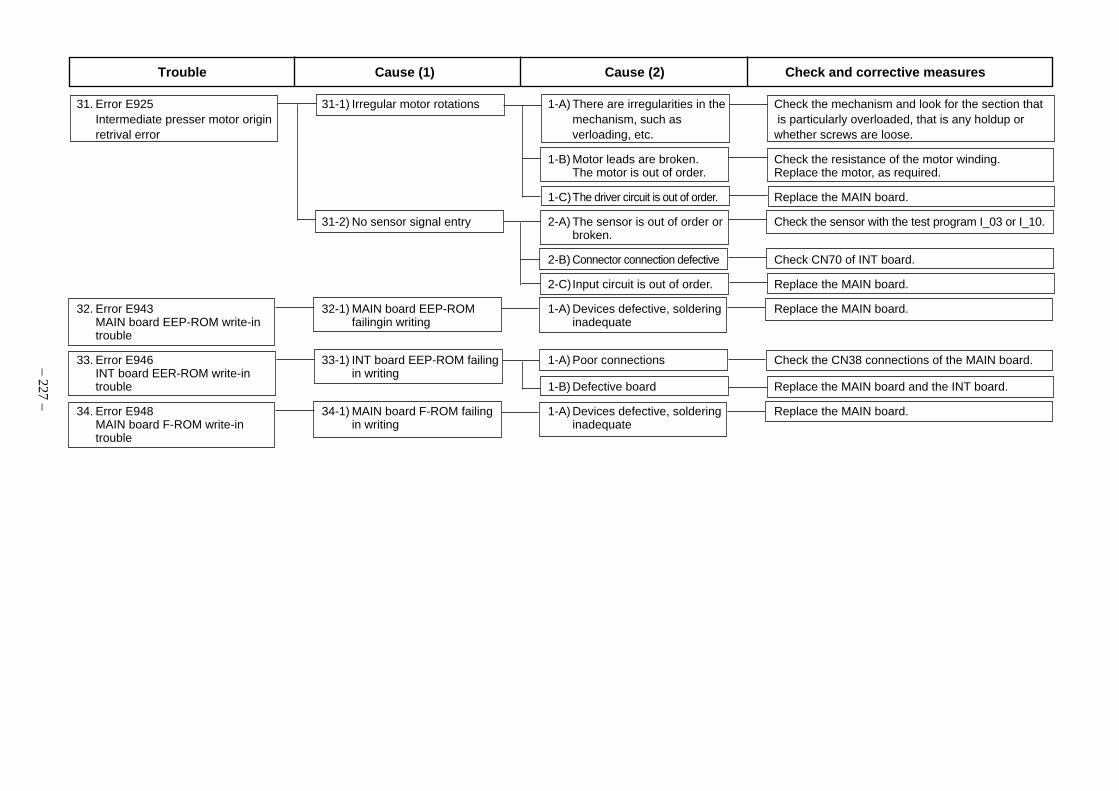
– 227 –
31. Error E925 31-1) Irregular motor rotations 1-A) There are irregularities in the Check the mechanism and look for the section thatIntermediate presser motor origin mechanism, such as is particularly overloaded, that is any holdup orretrival error verloading, etc. whether screws are loose.
1-B) Motor leads are broken. Check the resistance of the motor winding.The motor is out of order. Replace the motor, as required.
1-C)The driver circuit is out of order. Replace the MAIN board.
31-2) No sensor signal entry 2-A) The sensor is out of order or Check the sensor with the test program I_03 or I_10.broken.
2-B) Connector connection defective Check CN70 of INT board.
2-C)Input circuit is out of order. Replace the MAIN board.
32. Error E943 32-1) MAIN board EEP-ROM 1-A) Devices defective, soldering Replace the MAIN board.MAIN board EEP-ROM write-in failingin writing inadequatetrouble
33. Error E946 33-1) INT board EEP-ROM failing 1-A) Poor connections Check the CN38 connections of the MAIN board.INT board EER-ROM write-in in writingtrouble 1-B) Defective board Replace the MAIN board and the INT board.
34. Error E948 34-1) MAIN board F-ROM failing 1-A) Devices defective, soldering Replace the MAIN board.MAIN board F-ROM write-in in writing inadequatetrouble
Trouble Cause (1) Cause (2) Check and corrective measures
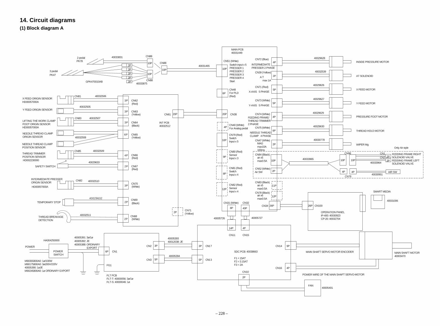
14. Circuit diagrams(1) Block diagram A
– 228 –
CN61 CN38
CN34CN32
CN11 CN15
CN14
CN16
CN17
CN13
CN2
CN3
CN1
20P 20P
2P
5P
5P
4P
6P
2P
26P8P 40P
6P
3P
5P
3P
5P
4P
9P
14P 4P
SDC PCB: 40038663
F1 = 15ATF2 = 3.15ATF3 = 2AFG1
CN81
CN10026P
2P
CN10
FAN
4P
4P
11P
12P
9P
8P
10P
12P
CN72 (Blue)
INTERMEDIATE PRESSER 2 PHASE
MAIN PCB40031449
CN51 (White)CN88
CN88
CN88
Switch input x 5PRESSER 1PRESSER 2PRESSER 3PRESSER 4Start
CN39 (Yellow)
X-AXIS 5 PHASE
Y-AXIS 5 PHASE
FEEDING FRAME/THREAD TRIMMER 2 PHASE
NEEDLE THREAD CLAMP 4 PHASE
A T max 1A
CN71 (Red)
CN73 (White)
CN74 (White)
CN75 (White)
CN47 (White)MAGmax10A100ms
CN84 (Black)air x5max0.5A
CN52 (White)Air SW
CN83 (Black)air x5max0.5A
air x6max0.5A
CN78 (Black)
CN62(Red)
(Red)
(Black)
(Yellow)
(Yellow)
CN63
CN64
CN65
CN66
(Red)
(White)
(White)
(Black)
CN67
6P
3P
3P
3P
4P
2P
HD00057000A
HD002230000
INT PCB40032512
CN85
CN82
CN83
3PHD00057000A
2P
2P
CN70
CN68
CN69
2P 4P
10P 10P 10P
CN98
2P
4P
CN78
AIR SW
2PCN1
CN22P
10P
10P
10P
2 pedalPK78
10P
2P
2P
2P
2P
2P
3 pedal
X FEED ORIGIN SENSOR
Y FEED ORIGIN SENSOR
NEEDLE THREAD CLAMPORIGIN SENSOR
NEEDLE THREAD CLAMPPOSITION SENSOR
THREAD TRIMMER POSITION SENSOR
SAFETY SWITCH
TEMPORARY STOP
THREAD BREAKAGEDETECTION
INTERMEDIATE PRESSER ORIGIN SENSOR
POWER
POWER SWITCH
HD00057000A
LIFTING THE WORK CLAMP FOOT ORIGIN SENSOR
PK47
CN48For PLD(Red)
CN40 (White)For Analog pedal
CN79 (Red)SwitchInput x 5
CN80 (Red)SensorInput x 3
CN82 (Red)
CN31 (White)
CN71(Yellow)
SensorInput x 4
CN81 (Red)SwitchInput x 4
6P
GPK470010AB
40031006
FLT PCBFLT-T: 40000056: 3ø/1øFLT-S: 40000046: 1ø
40005401
OPERATION PANELIP-400: 40030923CP-20: 40032704
MAIN SHAFT SERVO MOTOR ENCODER
POWER WIRE OF THE MAIN SHAFT SERVO-MOTOR
SMART MEDIA
MAIN SHAFT MOTOR40003470
WIPER Mg
THREAD HOLD MOTOR
Y FEED MOTOR
X FEED MOTOR
AT SOLENOID
INSIDE PRESSURE MOTOR
PRESSURE FOOT MOTOR
Only Air style
FEDDING FRAME RIGHT SOLENOID VALVEFEDDING FRAME LEFTSOLENOID VALVE
4000539340012038: JE
40005394
40005391: 3ø/1ø
M90355800A0: 1ø/100WM90175800A0: 3ø200V/220V40005390: 1øJEM90245800A0: 1ø ORDINARY EXPORT
40005392: JE40005388: ORDINARY EXPORT
HA004250000
40032511
40029632
40032510
40032509
40032508
40032507
40032505
40032506
40030778
40029630
40029629
40029627
40029626
40032539
40029628
40031465
40033831
40030951
4003396440029633
40005726 40005727
40033875
40033965

(2) Power supply circuit diagram A
– 229 –
POWER SWITCH
Green
Black
White
Red
FLT-T BOARD200V CONNECTIONS
SDC BOARD MAIN BOARD
Green
Black
White
Red
White
White
Yellow
Red
Orange
Black
Black
Black
Red
White
Black
Brown
White
Yellow

(3) Power supply circuit diagram B
– 230 –
POWER SWITCH
Green/Yellow
Gray
Gray
FLT-T BOARD100V CONNECTIONS
SDC BOARD MAIN BOARD
Green
Black
White
Red
White
White
Yellow
Red
Orange
Black
Black
Black
Red
White
Black
Brown
White
Yellow

(4) Power supply circuit diagram C
– 231 –
POWER SWITCH
Green/Yellow
Brown
Light Blue
FLT-S BOARD SDC BOARD MAIN BOARD
Green/Yellow
Brown
Light Blue
White
White
Yellow
Red
Orange
Black
Black
Black
Red
White
Black
Brown
White
Yellow

(5) Servo motor circuit diagram
– 232 –
ENCODER
SDC BOARD AC SERVO MOTOR
Black
Red
White
Green + Yellow
White (Drain line)
Black
Orange
Blue
Purple
Light Blue
Pink
Red
Yellow

(6) Sensor-pedal circuit diagram
– 233 –
INT BOARD
MAIN BOARD
Red
White
Black
X feed origin sensor
Y feed origin sensor
Lifting the work clampfoot origin sensor
Needle thread clamporigin sensor
Needle thread clampposition sensor
Thread trimmer positionsensor
Safety switch
Brown
Black
Blue
(Red)
Red
White
Black
Brown
Black
Blue
Brown
Black
Blue
Red
White
Black
Black
White
Red
White
Black
White
Black
Black (White)
(Black)
(White)
(Red)
(Red)
(Yellow)
(Black)
(Yellow)
(White)
Intermediate presserorigin sensor
TEMPORARY STOP
Thread breakagedetection

(7) MAIN•PANEL board circuit diagram
– 234 –
PANEL BOARDMAIN BOARD

(8) Motor•solenoid circuit diagram
– 235 –
MAIN BOARD
Red
Orange
Yellow
Blue
Black
X feed motor
Red
Orange
Yellow
Blue
Black
AT solenoid
White
Black
Wiper solenoid
(White)
(Yellow)
(White)
(Red)
Orange
Blue
Red
Yellow
(White)
Orange
Blue
Red
Yellow
(Blue)
Yellow
Red
Blue
Orange
White
Black
(White)
Y feed motor
Thread trimmer lifting the work clamp foot motor
Needle thread clamp motor
Intermediate presser motor
Black
White

(9) Air system circuit diagram
– 236 –
A Feeding frame cylinder (left)
B Feeding frame cylinder (right)
C Inverting cylinder
D Speed controller
E Solenoid valve
F ø 4 Air tube
G Manifold
H Filter regulator
I Regulator
J One-touch joint plug
One-touch joint socket
K Air cock
L ø 6 Air tube
Hose elbow
Hose nipple
Elbow union
T type tee
Plug
Barrel nipple
Pneumatic source
CN1
1-A 1-B
CN2
2-A 2-B
FU-05 (Option)
FU-05 (Option)
A B
C
F
I
D
E
G
JK
F
GL
H

15. Drawing of the table
PART No. : 40030949
40
R2 (all pe-
riphery)
– 237–
Z-Z (2pcs.)Control box mounting hole
Mor
e th
an 4
0
Top of table
17 drill
Draw stopper mounting position(1 position on rear side)
4 x 8 drill
9 drill, 20 depth Counterboredepth 17
30 drill, 51 depth Counterboredepth 16
R2 (all
pe-
riphe
ry)
Leg mounting hole(Rear side: 2 positions, drilldepth 10)

®
MARKETING & SALES H.Q.8-2-1, KOKURYO-CHO,CHOFU-SHI, TOKYO 182-8655, JAPANPHONE : (81)3-3480-2357 • 2358FAX : (81)3-3430-4909 • 4914
Copyright © 2006 JUKI CORPORATION.
All rights reserved throughout the world.
Please do not hesitate to contact our distributors or agents in your area for further information when necessary.* The description covered in this engineer's manual is subject to change for improvement of the
commodity without notice.06 · 01 Printed in Japan (E)
This manual uses environment-friendly soyink.
The environmental management system to promote and conduct1the technological and technical research, the development and
design of the products in which the environmental impact is consid-ered,
2the conservation of the energy and resources, and the recycling, inthe research, development, design, distribution, sale and mainte-nance service of the industrial sewing machines, household sew-ing machines and industrial-use robots, etc. and in the sale andmaintenance service of data entry system and in the purchase, dis-tribution and sale of the household commodities including thehealthcare products.