INSTRUCTION MANUAL - Grainger Industrial Supply - … and RK1240C Crimping Tools Greenlee / A...
12
INSTRUCTION MANUAL RK1240 and RK1240C 12-ton, Single-acting, Die-type Crimping Tools 99926989 © 2011 Greenlee Textron Inc. IM 1337 REV 7 9/11 Read and understand all of the instructions and safety information in this manual before operating or servicing this tool. Register this product at www.greenlee.com Serial Codes GAB and ADL
Transcript of INSTRUCTION MANUAL - Grainger Industrial Supply - … and RK1240C Crimping Tools Greenlee / A...

INSTRUCTION MANUAL
RK1240 and RK1240C 12-ton, Single-acting,
Die-type Crimping Tools
99926989 © 2011 Greenlee Textron Inc. IM 1337 REV 7 9/11
Read and understand all of the instructions and safety information in this manual before operating or servicing this tool.
Register this product at www.greenlee.com
Serial Codes GAB and ADL
RK1240 and RK1240C Crimping Tools
Greenlee / A Textron Company 4455 Boeing Dr. • Rockford, IL 61109-2988 USA • 815-397-70702
Description
The Greenlee RK1240 12-ton, Single-acting, Die-type Crimping Tool is intended to crimp splicing sleeves and termination lugs using industry standard dies. The single-acting ram requires hydraulic pressure to advance, and uses an internal spring to return.
The RK1240C has a PVC-covered crimping head.
These crimping tools require an external 700 bar (10,000 psi) hydraulic power source, such as Greenlee 975, 976-22, 980, and 980-22. They may also be powered using a hydraulic intensifier capable of developing 700 bar (10,000 psi), such as the Greenlee Utility Dynapress®.
Optional accessories include the following hydraulic hoses with one male and one female coupler:
• 90558509 3 m (10') Conductive
• 90558517 3 m (10') Non-Conductive
• 90558522 7.6 m (25') Non-Conductive
Safety
Safety is essential in the use and maintenance of Greenlee tools and equipment. This instruction manual and any markings on the tool provide information for avoiding hazards and unsafe practices related to the use of this tool. Observe all of the safety information provided.
Purpose of this Manual
This manual is intended to familiarize all personnel with the safe operation and maintenance procedures for the following Greenlee tools:
• RK1240 — Serial Code GAB
• RK1240C — Serial Code ADL
Keep this manual available to all personnel.
Replacement manuals are available upon request at no charge at www.greenlee.com.
All specifications are nominal and may change as design improvements occur. Greenlee Textron Inc. shall not be liable for damages resulting from misapplication or misuse of its products.
Dynapress is a registered trademark of Greenlee Textron Inc.
Loctite is a registered trademark of the Loctite Corporation.
KEEP THIS MANUAL
Table of Contents
Description .................................................................... 2
Safety ........................................................................... 2
Purpose of this Manual ................................................ 2
Important Safety Information ....................................3–4
Identification ................................................................. 5
Specifications ............................................................... 5
Setup ............................................................................ 6
Operation ...................................................................... 7
Die Selection ................................................................. 8
Connector Selection ...................................................... 8
Maintenance ................................................................. 9
Periodic Relief Valve Check .......................................... 9
Assembly ..................................................................... 10
Illustration and Parts List .......................................11–12
RK1240 and RK1240C Crimping Tools
Greenlee / A Textron Company 4455 Boeing Dr. • Rockford, IL 61109-2988 USA • 815-397-70703
IMPORTANT SAFETY INFORMATION
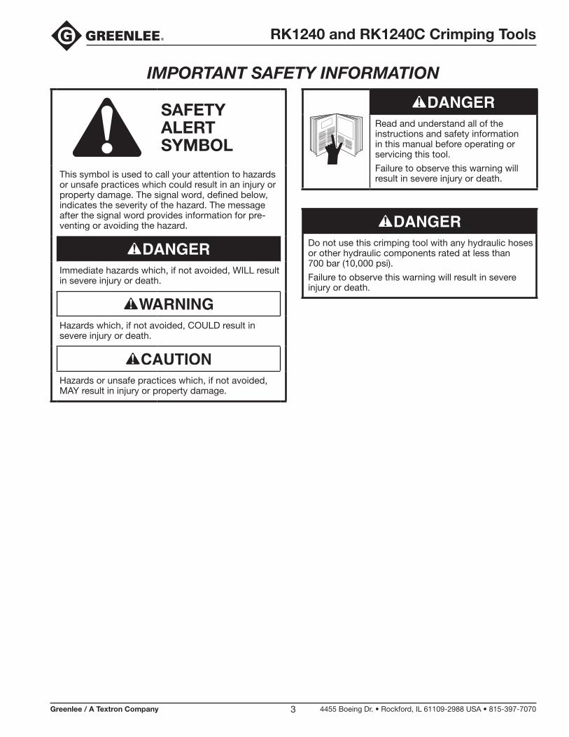
SAFETY ALERT SYMBOL
This symbol is used to call your attention to hazards or unsafe practices which could result in an injury or property damage. The signal word, defined below, indicates the severity of the hazard. The message after the signal word provides information for pre-venting or avoiding the hazard.
Immediate hazards which, if not avoided, WILL result in severe injury or death.
Hazards which, if not avoided, COULD result in severe injury or death.
Hazards or unsafe practices which, if not avoided, MAY result in injury or property damage.
Read and understand all of the instructions and safety information in this manual before operating or servicing this tool.
Failure to observe this warning will result in severe injury or death.
Do not use this crimping tool with any hydraulic hoses or other hydraulic components rated at less than 700 bar (10,000 psi).
Failure to observe this warning will result in severe injury or death.
RK1240 and RK1240C Crimping Tools
Greenlee / A Textron Company 4455 Boeing Dr. • Rockford, IL 61109-2988 USA • 815-397-70704
IMPORTANT SAFETY INFORMATION
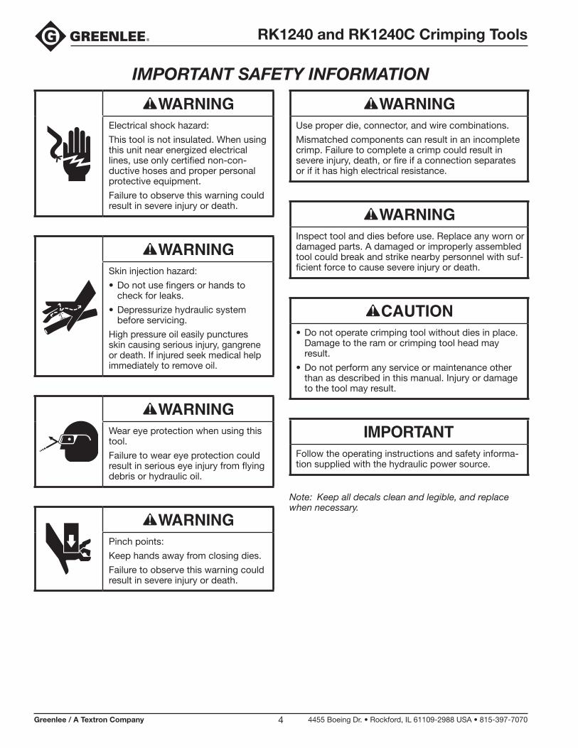
Electrical shock hazard:
This tool is not insulated. When using this unit near energized electrical lines, use only certified non-con-ductive hoses and proper personal protective equipment.
Failure to observe this warning could result in severe injury or death.
Skin injection hazard:
• Do not use fingers or hands to check for leaks.
• Depressurize hydraulic system before servicing.
High pressure oil easily punctures skin causing serious injury, gangrene or death. If injured seek medical help immediately to remove oil.
Wear eye protection when using this tool.
Failure to wear eye protection could result in serious eye injury from flying debris or hydraulic oil.
Pinch points:
Keep hands away from closing dies.
Failure to observe this warning could result in severe injury or death.
Use proper die, connector, and wire combinations.
Mismatched components can result in an incomplete crimp. Failure to complete a crimp could result in severe injury, death, or fire if a connection separates or if it has high electrical resistance.
Inspect tool and dies before use. Replace any worn or damaged parts. A damaged or improperly assembled tool could break and strike nearby personnel with suf-ficient force to cause severe injury or death.
• Do not operate crimping tool without dies in place. Damage to the ram or crimping tool head may result.
• Do not perform any service or maintenance other than as described in this manual. Injury or damage to the tool may result.
Follow the operating instructions and safety informa-tion supplied with the hydraulic power source.
Note: Keep all decals clean and legible, and replace when necessary.
RK1240 and RK1240C Crimping Tools
Greenlee / A Textron Company 4455 Boeing Dr. • Rockford, IL 61109-2988 USA • 815-397-70705
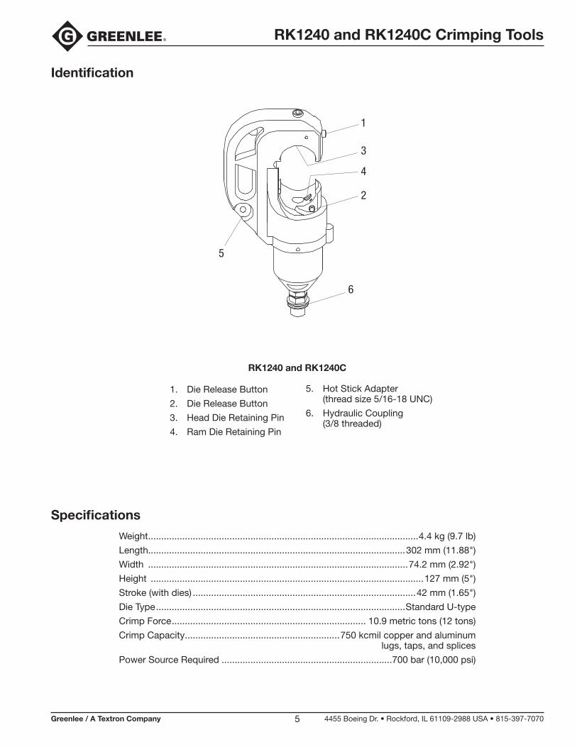
Identification
Specifications
Weight .......................................................................................................4.4 kg (9.7 lb)
Length..................................................................................................302 mm (11.88")
Width ...................................................................................................74.2 mm (2.92")
Height ........................................................................................................127 mm (5")
Stroke (with dies) .....................................................................................42 mm (1.65")
Die Type ...............................................................................................Standard U-type
Crimp Force .......................................................................... 10.9 metric tons (12 tons)
Crimp Capacity ...........................................................750 kcmil copper and aluminum lugs, taps, and splices
Power Source Required .................................................................700 bar (10,000 psi)
RK1240 and RK1240C
1. Die Release Button
2. Die Release Button
3. Head Die Retaining Pin
4. Ram Die Retaining Pin
5. Hot Stick Adapter (thread size 5/16-18 UNC)
6. Hydraulic Coupling (3/8 threaded)
1
2
3
4
6
5
RK1240 and RK1240C Crimping Tools
Greenlee / A Textron Company 4455 Boeing Dr. • Rockford, IL 61109-2988 USA • 815-397-70706
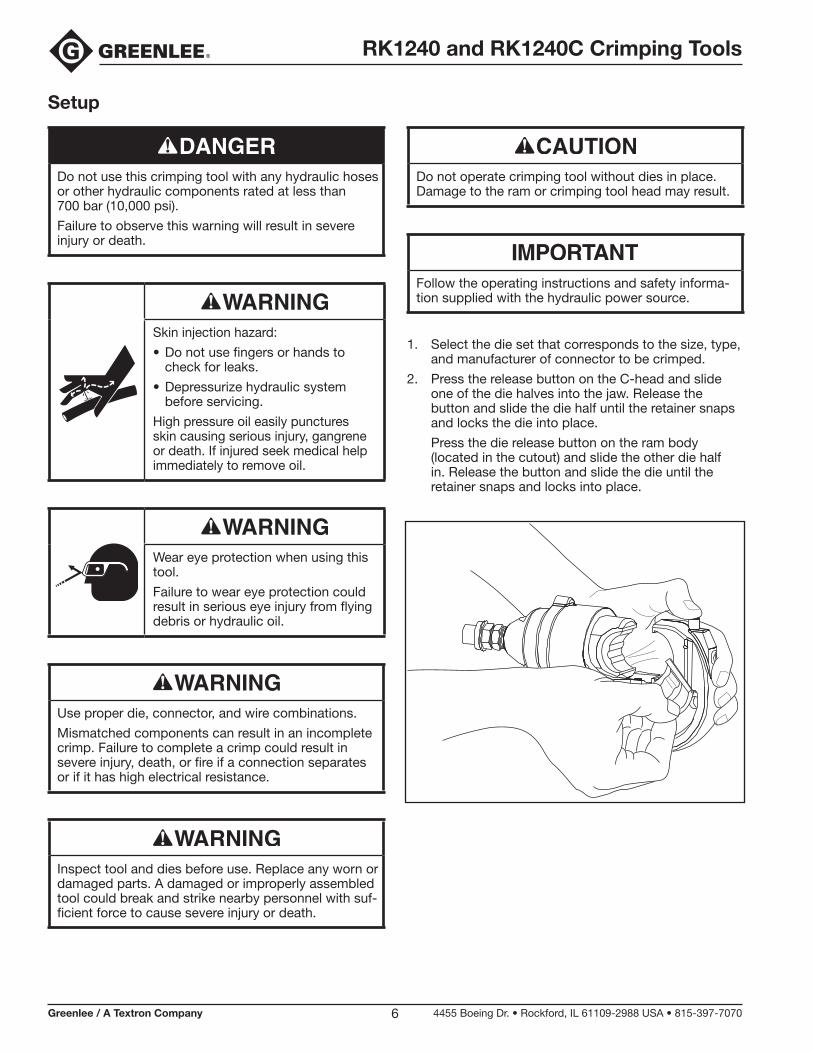
Setup
Do not use this crimping tool with any hydraulic hoses or other hydraulic components rated at less than 700 bar (10,000 psi).
Failure to observe this warning will result in severe injury or death.
Skin injection hazard:
• Do not use fingers or hands to check for leaks.
• Depressurize hydraulic system before servicing.
High pressure oil easily punctures skin causing serious injury, gangrene or death. If injured seek medical help immediately to remove oil.
Wear eye protection when using this tool.
Failure to wear eye protection could result in serious eye injury from flying debris or hydraulic oil.
Use proper die, connector, and wire combinations.
Mismatched components can result in an incomplete crimp. Failure to complete a crimp could result in severe injury, death, or fire if a connection separates or if it has high electrical resistance.
Inspect tool and dies before use. Replace any worn or damaged parts. A damaged or improperly assembled tool could break and strike nearby personnel with suf-ficient force to cause severe injury or death.
Do not operate crimping tool without dies in place. Damage to the ram or crimping tool head may result.
Follow the operating instructions and safety informa-tion supplied with the hydraulic power source.
1. Select the die set that corresponds to the size, type, and manufacturer of connector to be crimped.
2. Press the release button on the C-head and slide one of the die halves into the jaw. Release the button and slide the die half until the retainer snaps and locks the die into place.
Press the die release button on the ram body (located in the cutout) and slide the other die half in. Release the button and slide the die until the retainer snaps and locks into place.

RK1240 and RK1240C Crimping Tools
Greenlee / A Textron Company 4455 Boeing Dr. • Rockford, IL 61109-2988 USA • 815-397-70707
Operation
Electrical shock hazard:
This tool is not insulated. When using this unit near energized electrical lines, use only certified non-con-ductive hoses and proper personal protective equipment.
Failure to observe this warning could result in severe injury or death.
Pinch points:
Keep hands away from closing dies.
Failure to observe this warning could result in severe injury or death.
Note: When using KC12-type dies, complete the number of crimps listed on the “Connector Selection” chart in this manual. For other dies, complete the number of crimps specified by the manufacturer.
1. Prepare the cable by stripping off the appropriate amount of insulation.
2. Select a connector that corresponds to the conduc-tor and the application.
3. Insert the conductor into the connector. Position the connector as shown.
4. Activate the hydraulic power source until the ram has advanced and the crimp is completed.
Note: To assure a complete crimp, verify that the power source has reached 700 bar (10,000 psi). Refer to the “Periodic Relief Valve Check” in this manual.
5. Stop the power source and allow the ram to retract.

RK1240 and RK1240C Crimping Tools
Greenlee / A Textron Company 4455 Boeing Dr. • Rockford, IL 61109-2988 USA • 815-397-70708
Die SelectionRefer to “Connector Selection” for brand names and model numbers of appropriate lugs as well as crimping instructions.
Crimps made with this tool and KC12-type or KA12-type dies are cUL and UL classified when used with the appropriate conductor and connectors listed below.
Dies for Copper ConnectorsCatalog Number
UPC Number
CableSize Color Code No. of
CrimpsKC12-8 10996 8 AWG Red 1
KC12-6 10997 6 AWG Blue 1
KC12-4 10998 4 AWG Gray 1
KC12-2 10999 2 AWG Brown 1
KC12-1 11003 1 AWG Green 1
KC12-1/0 11004 1/0 AWG Pink 1
KC12-2/0 11007 2/0 AWG Black 1
KC12-3/0 11010 3/0 AWG Orange 1
KC12-4/0 11011 4/0 AWG Purple 1
KC12-250 11012 250 kcmil Yellow 1
KC12-300 11013 300 kcmil White 2
KC12-350 11014 350 kcmil Red 2
KC12-400 11015 400 kcmil Blue 2
KC12-500 11016 500 kcmil Brown 2
KC12-600 11018 600 kcmil Green 2
KC12-750 11020 750 kcmil Black 2
Dies for Aluminum ConnectorsCatalog Number
UPC Number
CableSize Color Code No. of
CrimpsKA12-8 22084 8 AWG Blue 1
KA12-6 22085 6 AWG Gray 1
KA12-4 22086 4 AWG Green 1
KA12-2 22087 2 AWG Pink 1
KA12-1 22088 1 AWG Gold 1
KA12-1/0 22089 1/0 AWG Tan 1
KA12-2/0 22090 2/0 AWG Olive 2
KA12-3/0 22121 3/0 AWG Ruby 2
KA12-4/0 22122 4/0 AWG White 2
KA12-250 22123 250 kcmil Red 2
KA12-300 22124 300 kcmil Blue 2
KA12-350 22125 350 kcmil Brown 2
KA12-400 22126 400 kcmil Green 3
KA12-500 22127 500 kcmil Pink 3
KA12-600 22128 600 kcmil Black 3
KA12-750 22129 750 kcmil Yellow 3
Connector SelectionTool Range: 8 AWG to 750 kcmilWhen used with KC12-type dies, this tool is cUL and UL classified for use with the following connector brands:
Short
Long
Short
Long
BARRELTYPE
8 AWG to250 kcmil:
1 crimp
300 to750 kcmil:2 crimps
NUMBEROF CRIMPS*
VHSS
VHS
VHCS
VHCL
ANDERSON
CSP
CU
CTL-2/CTL
CTL-L/LCN
BLACKBURN®
YS-L
YS
YA-2LN/YA-L/YA-2L;YA/YA-L-TC/
YA-L-2TC
YA/YAZYA-2N/YA-2TC
YAZ-2N/YAZ-2TC
BURNDY
CT
CTL
CSWCRA/CRB
CRC
CLN, CLWCRA-L/CRB-L
CRA-2/CRB-2LCRC-2L
ILSCO
SCSSSCS
SCLSCH
LCASLCALCD
LCAN
LCBLCC
PANDUIT
54504 to54523-TB
54804 to54823
54104 to54123-TB;54204 to54223
54930BE to54923BE;
54850BE to54880BE
T&B
BCU
BBCU
BLU
BBLU
PENN-UNION
CONNECTORTYPE
CopperSplices
CopperLugs
When used with KA12-type dies, this tool is cUL and UL classified for use with the following connector brands:
8 to1/0 AWG:1 crimp
2/0 AWG to350 kcmil:2 crimps
400 to750 kcmil:3 crimps
NUMBEROF CRIMPS*ANDERSON
VACS
VACL
BLACKBURN®
ASP
ATL
BURNDY
YS-A
YA-AYA-ATN
ILSCO
AS
ACL/ACN2ACL/2ACN
PANDUIT
SA
LAALAB
T&B
60501 to60578
60101 to60176;
60230 to60278
PENN-UNION
PIK
BLUA
CONNECTORTYPE
Dual-ratedAluminum
Splices
Dual-ratedAluminum
Lugs
95R7
* Use the number of crimps listed in this column instead of the number provided with the connector.

RK1240 and RK1240C Crimping Tools
Greenlee / A Textron Company 4455 Boeing Dr. • Rockford, IL 61109-2988 USA • 815-397-70709
Maintenance
• Keep the tool clean. Use the tool with care to keep dirt and grit out of the hydraulic system. Contamination is the most common cause of failure for hydraulic tools.
• Store the tool in its original case with the ram fully retracted.
• Occasionally lubricate the die release button assemblies. A molybdenum disulfide grease is recommended.
• Inspect the hydraulic hoses periodically.
• Periodically verify that the power source reaches 700 bar (10,000 psi). Refer to the “Periodic Relief Valve Check” in this manual.
Periodic Relief Valve Check
Skin injection hazard:
• Do not use fingers or hands to check for leaks.
• Depressurize hydraulic system before servicing.
High pressure oil easily punctures skin causing serious injury, gangrene or death. If injured seek medical help immediately to remove oil.
Wear eye protection when using this tool.
Failure to wear eye protection could result in serious eye injury from flying debris or hydraulic oil.
Pinch points:
Keep hands away from closing dies.
Failure to observe this warning could result in severe injury or death.
Inspect tool and dies before use. Replace any worn or damaged parts. A damaged or improperly assembled tool could break and strike nearby personnel with suf-ficient force to cause severe injury or death.
• Do not operate crimping tool without dies in place. Damage to the ram or crimping tool head may result.
• Do not perform any service or maintenance other than as described in this manual. Injury or damage to the tool may result.
Periodically verify that your hydraulic power source is supplying between 9600 and 10,400 psi (662 and 717 bar).
Use a test-quality pressure gauge on the supply line from the hydraulic power source.
1. Refer to the instructions supplied with the pressure gauge.
2. Stop the flow of hydraulic oil from the power source.
3. Connect the pressure gauge to the supply line of the power source.
4. Install the set of test dies into the crimping tool.
5. Activate the power source until the ram has advanced and the power source reaches relief pressure. The pressure gauge should read between 9600 psi and 10,400 psi (662 bar and 717 bar) .
6. Release the pressure by stopping flow from your power source. The ram will retract.
If crimp pressures are low, the hydraulic power source relief valve may need adjustment.
Relief valve adjustments must be performed accord-ing to the instructions provided with the hydraulic power source.

RK1240 and RK1240C Crimping Tools
Greenlee / A Textron Company 4455 Boeing Dr. • Rockford, IL 61109-2988 USA • 815-397-707010
Step 4. Installing the Ram
Assembly (refer to the Illustration)
1. Lubricate the Die Retainer (4) and Die Release Button (2) with a Molybdenum Disulfide grease. Assemble them into the C-head and install Drive Pin (3). Add two drops of Loctite® 242® Threadlocker to Screw (6), install Spring (5) from the top of the C-head and retain with Screw (6). Adjust the Screw (6) so that the Die Retainer (4) is flush with the head when the Die Release Button (2) is pressed.
2. Inspect the external surface of the ram and the inside surface of the cylinder for nicks, gouges or other imperfections. Replace the ram or cylinder if necessary.
3. Assemble Spring (11), Die Retaining Pin (10) and Die Release Button (12) to the Ram (15). Retain with the Roll Pin (9).
4. Tilt and slide the ram (15) through the opening in the C-head (1). Align the T-shaped protrusion on the ram with the T-shaped groove in the C-head and assemble the ram to the head (see below).
5. Slide the Washer (16) and Wiper (17) onto the Ram (15) as far as they will go. Place the U-cup Seal (21) on the Ram.
6. Assemble the Extension Spring (19) to the two Spring Retainers (18,20).
7. Thread the Spring Retainer (20) into the base of the Cylinder (23), use a 5mm Allen wrench to tighten the spring retainer.
8. Lubricate the O-ring (22) and Backup Ring (21) and threads on the cylinder and C-head.
9. Slide the ram assembly down the C-head and assemble into the cylinder (23) far enough for full O-ring and Backup ring engagement.
10. Slip the cylinder into the base of the C-head and start threading them together. Continue to thread the cylinder into the C-head until the cylinder con-tacts the C-head.
11. Lock the C-head in place with the Set Screw (7) .
12. Install Nylon Washer (14) and 8mm Screw (13) through the ram and tighten securely.
13. Use Pipe Sealer and assemble the 3/8" NPT Pipe (24) to the 3/8 Coupler (25). Assemble to the cylinder.
RK1240 and RK1240C Crimping Tools
Greenlee / A Textron Company 4455 Boeing Dr. • Rockford, IL 61109-2988 USA • 815-397-707011
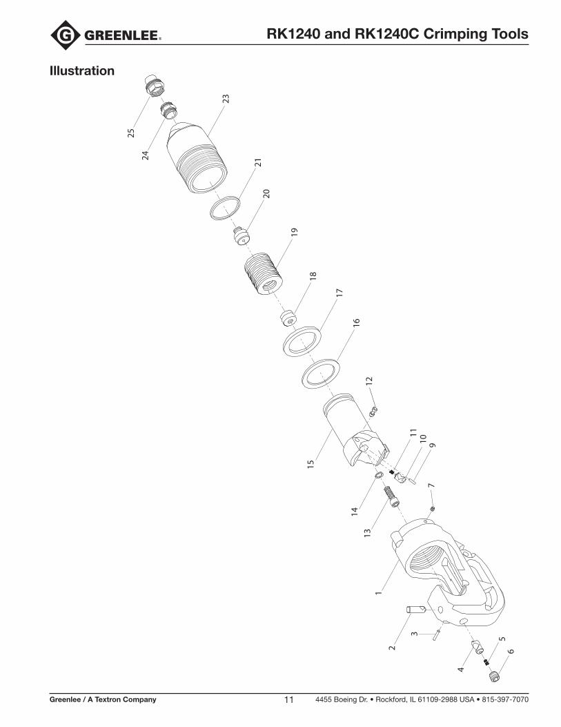
Illustration
653
21
1314
7910
11
12
15
16
17
18
19
2021
23
24
25
4
RK1240 and RK1240C Crimping Tools
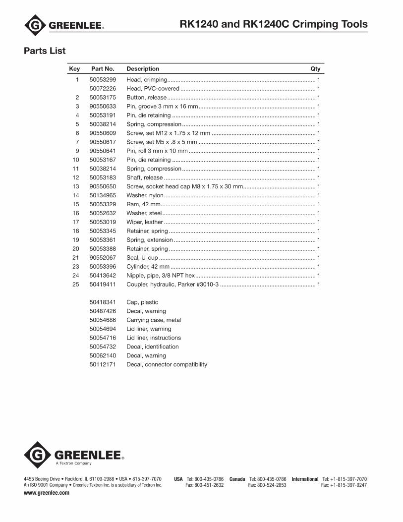
Parts List
Key Part No. Description Qty
1 50053299 Head, crimping .......................................................................................... 1
50072226 Head, PVC-covered .................................................................................. 1
2 50053175 Button, release .......................................................................................... 1
3 90550633 Pin, groove 3 mm x 16 mm ....................................................................... 1
4 50053191 Pin, die retaining ....................................................................................... 1
5 50038214 Spring, compression ................................................................................. 1
6 90550609 Screw, set M12 x 1.75 x 12 mm ............................................................... 1
7 90550617 Screw, set M5 x .8 x 5 mm ....................................................................... 1
9 90550641 Pin, roll 3 mm x 10 mm ............................................................................. 1
10 50053167 Pin, die retaining ....................................................................................... 1
11 50038214 Spring, compression ................................................................................. 1
12 50053183 Shaft, release ............................................................................................ 1
13 90550650 Screw, socket head cap M8 x 1.75 x 30 mm ............................................ 1
14 50134965 Washer, nylon ............................................................................................ 1
15 50053329 Ram, 42 mm .............................................................................................. 1
16 50052632 Washer, steel ............................................................................................. 1
17 50053019 Wiper, leather ............................................................................................ 1
18 50053345 Retainer, spring ......................................................................................... 1
19 50053361 Spring, extension ...................................................................................... 1
20 50053388 Retainer, spring ......................................................................................... 1
21 90552067 Seal, U-cup ............................................................................................... 1
23 50053396 Cylinder, 42 mm ........................................................................................ 1
24 50413642 Nipple, pipe, 3/8 NPT hex ......................................................................... 1
25 50419411 Coupler, hydraulic, Parker #3010-3 .......................................................... 1
50418341 Cap, plastic
50487426 Decal, warning
50054686 Carrying case, metal
50054694 Lid liner, warning
50054716 Lid liner, instructions
50054732 Decal, identification
50062140 Decal, warning
50112171 Decal, connector compatibility
4455 Boeing Drive • Rockford, IL 61109-2988 • USA • 815-397-7070An ISO 9001 Company • Greenlee Textron Inc. is a subsidiary of Textron Inc.
USA Tel: 800-435-0786 Fax: 800-451-2632
Canada Tel: 800-435-0786 Fax: 800-524-2853
International Tel: +1-815-397-7070 Fax: +1-815-397-9247
www.greenlee.com