Instruction Manual for Tie Rod Type Cylinder - … · §6.Torque specifications for tie-rod, hex...
27
Instruction Manual for Tie Rod Type Cylinder K Series : 3.5MPa F Series : 7・14MPa T Series : 21MPa ・ Thoroughly read the instruction manual before use for correct operation. ・ Be sure to turn OFF the power switch, completely shut down the hydraulic source and discharge the residual pressure before mounting and maintenance of the cylinder. ・ Be sure to apply nominal pressure when using the cylinder. ・ When injecting hydraulic fluid into the cylinder, please take great care to prevent physical injury due to the rapid movement of the mounting part. 安全に関するご注意 ・ Do not attempt to tamper with the cushion plug, air bleeding plug, or check plug during operation.
Transcript of Instruction Manual for Tie Rod Type Cylinder - … · §6.Torque specifications for tie-rod, hex...

Instruction Manual
for Tie Rod Type Cylinder
K Series : 3.5MPa
F Series : 7・14MPa
T Series : 21MPa
・ Thoroughly read the instruction manual before use for correct operation.
・ Be sure to turn OFF the power switch, completely
shut down the hydraulic source and discharge
the residual pressure before mounting and maintenance of the cylinder.
・ Be sure to apply nominal pressure when using the cylinder.
・ When injecting hydraulic fluid into the cylinder,
please take great care to prevent physical injury due to the rapid movement of the mounting part.
安全に関するご注意
・ Do not attempt to tamper with the cushion plug, air bleeding plug, or check plug during operation.

1/26
Index
§1.CAUTIONS FOR OPERATION (1-1).Cautions for test run P 2 (1-2).Precautions for normal use P 6 §2.Cylinder Disassembly (2-1).Cautions for Cylinder Disassembly P 7 (2-2).Cylinder Disassembly P 7 Valve disassembly P10 §3.Guide for cylinder assembly (3-1).Cautions for cylinder assembly P13 (3-2).Cylinder assembly P13 Tightening of tie-rod (hex bolts) P16 Valve assembly P16 §4.Caution for maintenance inspection P21 §5. Precautions for cylinder mounting P21 §6.Torque specifications for tie-rod, hex bolt P24 §7.Indication of cylinder label P27 * Agree with changing the contents in this manual without any permission.

2/26
§1.CAUTIONS FOR OPERATION
(1-1) Cautions for test run
1. When using the cylinder for the first time after installation, apply
0.3-0.5MPa of pressure to check the smooth operation, and open the
air-bleeder bolt a half-turn counterclockwise at 20-50mm before the end of
the stroke until the oil in the cylinder is bled out free of air, and tighten
the air-bleeder bolt again. Under normal conditions, most of the air is
removed during the first pass. Be careful not to loosen the air-bleeder bolt
too much during this operation and not to apply too much pressure on the
cylinder for test run.
(Caution) When air is still remained in the cylinder, white hydraulic oil
comes out from the air bleeder bolt. In this case, repeat the
air-bleeding procedure until the oil becomes transparent.
With cushion option Without cushion option
(F,T Series) (F,T Series)
With cushion option (K Series) Without cushion option (K Series)

3/26
After completing the air bleeding operation, tighten the air bleeder bolt with the
torque shown in the table below to check that there are no oil leakages.
【Tightening Torque for Air Bleeder Bolt】
F Series T Series K Series
Without
Cushion
With
Cushion
Without
Cushion
With
Cushion
Without
Cushion
With
Cushion
Φ32
Φ125
approx.
500~
650N・cm
Φ40
Φ100
approx.
500~
650N・cm
Φ32
Φ80
approx.
550~
700N・cm
Φ140
Φ250
approx.
600~
800N・cm
approx.
400~
500N・cm Φ125
Φ160
approx.
600~
800N・cm
approx.
400~
500N・cm Φ100
Φ160
approx.
550~
750N・cm approx.
800~
1000N・cm
2. Clean the inside of the supply pipes to the cylinder by pickling or other methods
and take extreme care not to flow debris and filings into the cylinder. Debris
and/or metallic filings generated from pipe set-up or improper cleaning can later
flow into the cylinder and cause damage on the packing, resulting in oil leakage.
Air entered into the system during supply line set-up must be bled out. Air
remained in the system may cause the following problems:
1) Air contamination with oil
2) Inability to control speed.
3) Damage on the packing due to increase in temperature caused by adiabatic
compression.
4) Transmission of vibration and shock to external parts.
3. After completing the air bleeding procedure, under a low hydraulic pressure,
operate the cylinder by gradually increasing the pressure to the specified level.
Keep the cylinder speed at about 50mm/sec during this operation.
4/26
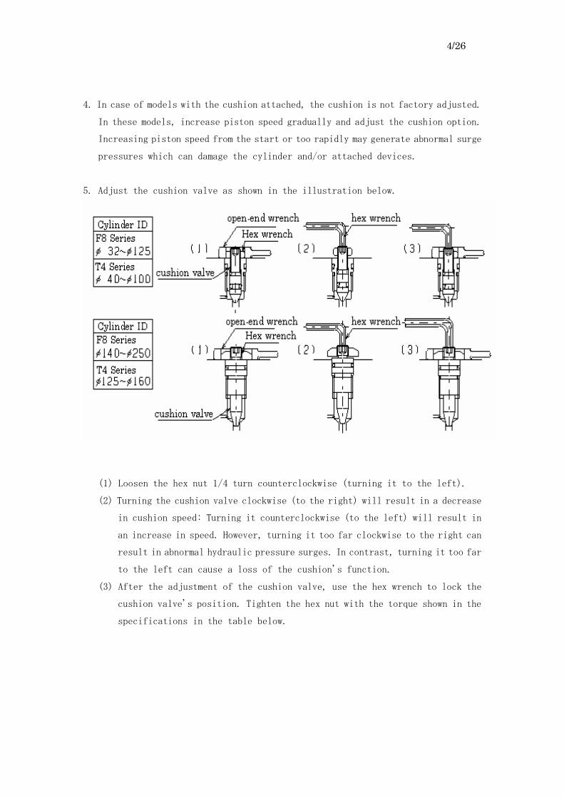
4. In case of models with the cushion attached, the cushion is not factory adjusted.
In these models, increase piston speed gradually and adjust the cushion option.
Increasing piston speed from the start or too rapidly may generate abnormal surge
pressures which can damage the cylinder and/or attached devices.
5. Adjust the cushion valve as shown in the illustration below.
(1) Loosen the hex nut 1/4 turn counterclockwise (turning it to the left).
(2) Turning the cushion valve clockwise (to the right) will result in a decrease
in cushion speed: Turning it counterclockwise (to the left) will result in
an increase in speed. However, turning it too far clockwise to the right can
result in abnormal hydraulic pressure surges. In contrast, turning it too far
to the left can cause a loss of the cushion's function.
(3) After the adjustment of the cushion valve, use the hex wrench to lock the
cushion valve's position. Tighten the hex nut with the torque shown in the
specifications in the table below.

5/26
(Caution 1) Excessive loosing the hex nut may cause fall-off.
(Caution 2) The cushion mechanism in the cylinder prevents damage on the
cylinder; however, its ability to absorb inertia forces is
limited, so it is necessary to exercise caution in adjustment.
【Cushion Valve Tightening Torque Specifications】
F Series T Series K Series
Φ32
Φ125
approx.
400-500N・cm
Φ40
Φ100
approx.
400-500N・cm
Φ32
Φ80
approx.
500-650N・cm
Φ140
Φ250
approx.
900-1000N・cm
Φ125
Φ160
approx.
900-1000N・cm
Φ100
Φ160
approx.
800-1000N・cm
6. The operation environment temperature and the oil temperature should not exceed
80℃ for the normal specification or 120℃ for the high temperature
specification. The heat resistance limits of the packing gaskets used in the
assembly are 80℃ for standard rated oil and 120℃ for high temperature rated oil.
Care should be taken to monitor and avoid radiated and transmitted heat.
7. Oil used in operation should be that recommended by the manufacturer or that
equivalent to the standard high-grade hydraulic oil.
8. Troubleshooting
When the cylinder does not operate, check the following:
(1) Failure to operate due to a lack of hydraulic pressure.
With the cylinder attached in place in the hydraulic line system, mount an
oil pressure gauge close to the cylinder to make sure that pressure is applied.
If not, remove the line connected to the cylinder and check that oil is reaching
the cylinder. If oil is not reaching the cylinder, check the lines back toward
the hydraulic pump to make sure that there are no oil leaks.
(2) The cylinder is overloaded beyond its output capacity.
Even if the cylinder is attached correctly, the cylinder is bound by overload.
To check if this is the case, remove the load from the cylinder, and try to
operate the cylinder only at low pressure.

6/26
9. When the cylinder will not operate at specified speed, check the following.
(1) Check that the load on the cylinder is not beyond its capacity.
(2) Check that foreign matter has not caught in the system and caused destruction
of the seal.
10. The cushion option will not operate under the following conditions:
(1) When cylinder speed is extremely slow.
(2) When cylinder speed is extremely high and the load is beyond cylinder
capacity.
(3) When the cushion valve is open.
(4) When the check ball is not effective.
(1-2) Precautions for normal use
1. Check the following items periodically after the cylinder has been placed in
operation.
(1) Check oil leakage from the cylinder and lines.
(2) Check the hydraulic tank to make sure that the fluid is free of water and debris.
(3) Check that the oil is not burned or contaminated.
(4) Make sure that supply lines are not loose.
(5) Check the cylinder mountings to make sure that there is no distortion or
stretching.
(6) Check the cylinder mounting bolts to make sure they are tightened in accordance
with specifications.
(7) Check noises coming from the cylinder. It could be indications of trouble.
2. The packing components are consumables and have to be replaced periodically. Make
sure that spare parts are always available. The shelf life of the packing is
normally one year. Store the spare part in a dry, cool, and dark place.
Ultraviolet light and humidity cause deterioration of the rubber materials used
in the packing as well as the distortion of the resin, so it is important to avoid
storage in areas with these factors.

7/26
§2. Cylinder Disassembly
(2-1) Cautions for Cylinder Disassembly
(1) Before attempting to remove the cylinder, make sure that line pressure is
zero and that the electrical power supply has been turned off.
(2) During disassembly, care must be taken to protect the rod front threads,
port threads, and rod surface from damage. For example, dropping banging
on the parts may cause damage to the thread surfaces that makes them unfit
for further use.
(3) Be careful not to allow the parts to contact with oils other than those
used in the system. Contact with dissimilar oils may cause chemical
changes, resulting in seal swelling.
(2-2) Cylinder Disassembly
(1) Loosen hex nut (20), and remove retainer (18), and rod bushing (14). During
this operation, be careful not to damage the piston rod (11) with the wrench
during removal or by banging it against other parts. When removing the rod
bushing, pay attention so as not to damage the rod bushing or packing.

8/26
(2) Remove the head cover (13) and rod cover (12) from the cylinder tube (10),
and then the piston/piston rod (15/11) assembly.
(3) Under normal conditions, Locktite is applied on the piston, so the piston
cannot be disassembled.
(4) As the front surface is flat copper, follow the illustrations when removing
the dust packing (3), rod packing (2), and piston packing (1).

9/26
(5) Cushion valve disassembly
-1) Remove hex nut (27).
-2) Use the cushion plug disassembly tool (Horiuchi Machinery Mfg., sold
separately) to remove the cushion plug (26) and cushion valve assembly (23).
-3) Use a hex wrench to remove the cushion valve lower than the cushion plug.
-1) Remove the hex nut (27).
-2) Use a hex wrench to remove the cushion valve upper than the cover.

10/26
-1) Remove hex nut (27).
-2) Remove the needle gasket (36).
-3) Remove the cushion valve from the cover using a hex wrench.
(6) Air-bleed valve disassembly (with cushion)
-1) Loosen the air-bleed valve (28), and remove the air-bleed plug and spring (31),
and metal check-ball (32).
-2) Remove the air-bleed bolt (29) and the metal checkball (30) from the air-bleed
cover side.

11/26
-1) Loosen check plug (33) and remove from cover.
-2) Remove the check spring (34), metal check ball (35), and valve gasket (37)
as shown in the illustration.
-1) Remove the air bleed bolt (29) from cover.
-2) Remove the metal check ball (30).

12/26
(7) Check valve disassembly
-1) Loosen check plug (33) and remove from cover.
-2) Remove the check spring (34) and metal check ball (35).
-1) Loosen check plug (33) and remove from cover.
-2) Remove the check spring (34), metal check ball (35), and valve gasket (37)
from the cover.

13/26
§3. Guide for cylinder assembly.
(3-1) Cautions for cylinder assembly
1. Wash parts carefully before assembling.
2. Inspect all parts for damage or abnormalities before attempting assembly.
Fix or replace all damaged parts.
3. Inspect the U-packing and O-rings, etc. for irregularities or deformities.
If irregularities and/or deformities are found, replace them with new parts.
(3-2) Cylinder assembly
1. Inserting the piston packing.
Insert the packing as shown in the illustration with paying attention not
to weal in the wrong direction.
2. Inserting tube gasket
(1) Insert the O-ring ④ as shown in the illustration in the head cover section.
(2) Insert the O-ring (4-1) and back-up ring (4-2) as shown in the illustration
in the head cover section.

14/26
(3) Insert the surface-face seal (4) as shown in the illustration in the head
cover section.
3. Lubricate the cylinder tube using the same kind of oil used in operation and insert
it into the head cover. Take care so that debris does not enter during this
operation.
4. Insert the piston/piston rod assembly into the cylinder tube with paying attention
not to damage the packing during insertion.

15/26
5. After inserting the piston/piston rod assembly, attach the rod cover. Take care
so that the cylinder tube does not remove from the head cover during this operation.
(Caution) Before attaching the rod cover, grease the O-ring in the rod cover as well
as the head cover assembly.
6. Attach the O-ring (6), rod packing, and dust packing to the rod bushing. Take care
not to seal in the wrong direction.
7. After attaching the rod bushing, grease the seal. After greasing the seal, attach
to rod cover. Wrap the piston rod bolt threads with protective tape to prevent
damaging inside surfaces and/or seal of the rod bushing. Also pay attention so
as not to damage surfaces by banging with the wrench being used.
16/26
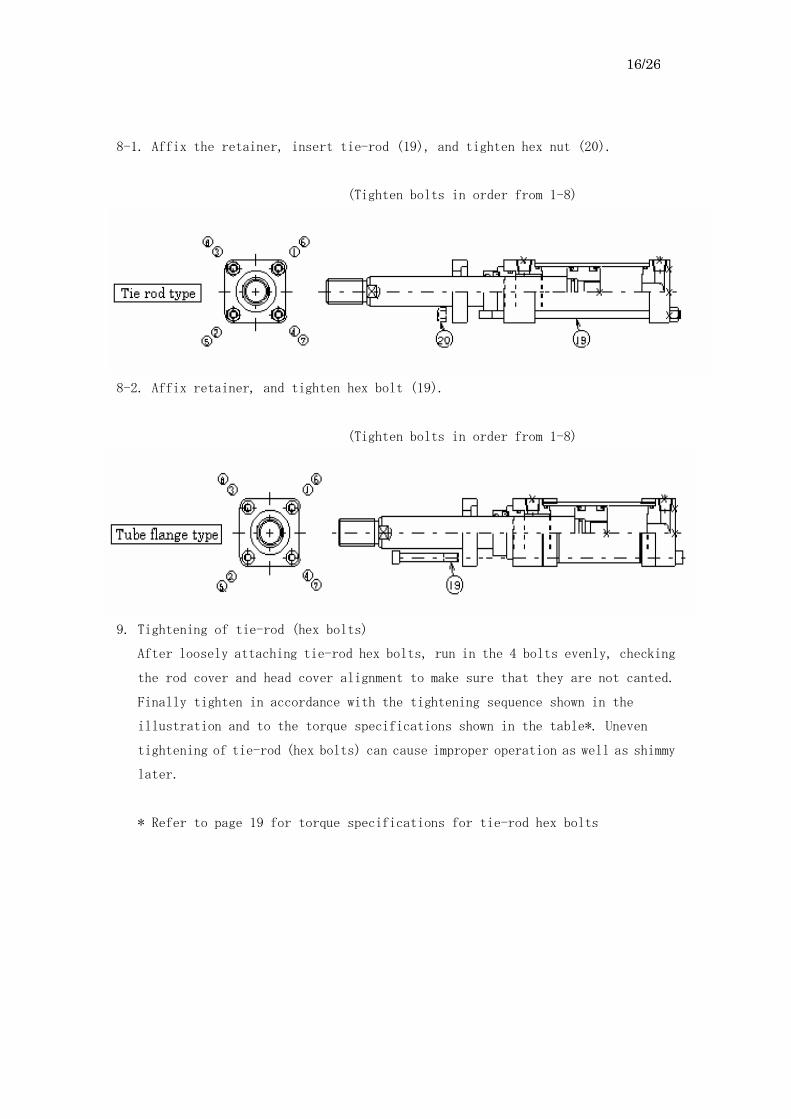
8-1. Affix the retainer, insert tie-rod (19), and tighten hex nut (20).
(Tighten bolts in order from 1-8)
8-2. Affix retainer, and tighten hex bolt (19).
(Tighten bolts in order from 1-8)
9. Tightening of tie-rod (hex bolts)
After loosely attaching tie-rod hex bolts, run in the 4 bolts evenly, checking
the rod cover and head cover alignment to make sure that they are not canted.
Finally tighten in accordance with the tightening sequence shown in the
illustration and to the torque specifications shown in the table*. Uneven
tightening of tie-rod (hex bolts) can cause improper operation as well as shimmy
later.
* Refer to page 19 for torque specifications for tie-rod hex bolts
17/26
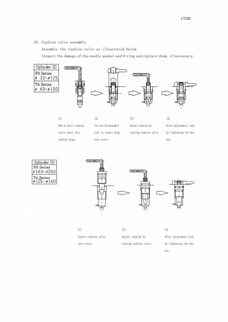
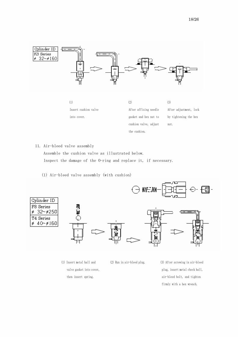
10. Cushion valve assembly
Assemble the cushion valve as illustrated below.
Inspect the damage of the needle gasket and O-ring and replace them, if necessary.
(1) (2) (3) (4)
Run in until cushion Use the disassembly Adjust cushion by After adjustment, lock
valve seats into tool to insert plug turning cushion valve. by tightening the hex
cushion plug. into cover. nut.
(1) (2) (3)
Insert cushion valve Adjust cushion by After adjustment,lock
into cover. turning cushion valve. by tightening the hex
nut.
18/26
(1) (2) (3)
Insert cushion valve After affixing needle After adjustment, lock
into cover. gasket and hex nut to by tightening the hex
cushion valve, adjust nut.
the cushion.
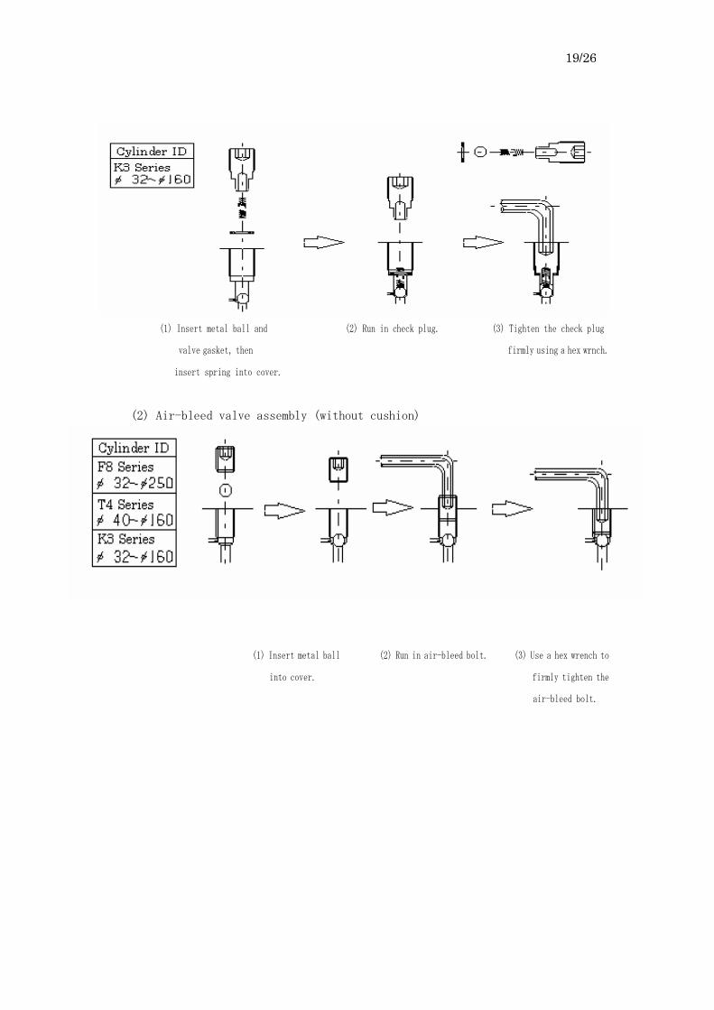
11. Air-bleed valve assembly
Assemble the cushion valve as illustrated below.
Inspect the damage of the O-ring and replace it, if necessary.
(1) Air-bleed valve assembly (with cushion)
(1) Insert metal ball and (2) Run in air-bleed plug. (3) After screwing in air-bleed
valve gasket into cover, plug, insert metal check ball,
then insert spring. air-bleed bolt, and tighten
firmly with a hex wrench.
19/26
(1) Insert metal ball and (2) Run in check plug. (3) Tighten the check plug
valve gasket, then firmly using a hex wrnch.
insert spring into cover.
(2) Air-bleed valve assembly (without cushion)
(1) Insert metal ball (2) Run in air-bleed bolt. (3) Use a hex wrench to
into cover. firmly tighten the
air-bleed bolt.

20/26
12. Check valve assembly
(1) Assembly of check valve
Assemble the check valve as illustrated below.
Inspect the damage of the O-ring and replace it if necessary.
(1) Insert metal ball, then (2) Screw in check plug. (3) Use a hex wrench to
insert spring into cover. firmly tighten the
check plug.
(1) Insert metal ball and (2) Screw in check plug. (3) Use a hex wrench to
valve gasket, then firmly tighten the
inset spring. check plug.
21/26
§4. Caution for maintenance inspection
1. Pay full attention to the following cases to avoid the damage of the cylinder.
-1) When the piston given a greater inersia force (due to excessive force or
high speed) is rapidly stopped, the following disorders are caused by
accidental excessive pressure or force.
a) An inflation of the cylinder tube
b) Damage on or deformation of the mounting tools or bolts
c) Damage on the thread of the piston rod
d) Damage on or deformation of the cylinder mounting foundation and frame
2. Pay full attention to the following cases to prevent dusts from getting into
the cylinder.
-1) When the cylinder port is kept open for a long time without plugging
* Be sure to apply the rust-proof fluid or applied fluid and plug it when
leaving the cylinder for a long time.
-2) When the ambient air is strongly acidic or alkaline, the hard chrome plating
on the rod is gradually peeled off as time goes by. The pieces of the plating
may get into the cylinder.
-3) Careless flushing In the case of flushing after the piping, perform it after making a bypass
circuit to prevent dust from getting into the cylinder.
3. It is necessary to perform periodical check (disassembly and inspection) every
year.
-1) Disassemble the cylinder in accordance with the user’s manual. Then
reassemble it after cleaning and inspection of the cylinder, and
replacement of parts.
-2) Inspect the leakage and the operation before reinstallation.
-3) Replace packing and gaskets with new ones at the periodical inspection.
§5. Precautions for cylinder mounting
To ensure the full performance of the cylinder and promote long service life, follow
the instructions below. It is important to keep the load at levels below the upper limits.

22/26
1. Mounting attachment
The cylinder load and mounting attachment should not be set up as shown in
illustration
In addition, when the stroke is long, a crevice, knuckle joint, or a ball joint
should be used.
2. Foot-type cylinder (LA, LB, LC)
The foot-type cylinder is normally attached with bolts; however, this may not
be the best mounting practice because of the possibility of horizontal
movement by load. In order to prevent this, affix a stopper to the mounting
base.

23/26
3. Flange type (FA, FB, FC, FD)
4. Trunnion type cylinder (TC, TA)
In case of (b), the trunnion axis is bent and stress on the trunnion can cause
failure.
5. Crevice-type cylinder (CA,CB)
When the crevice-type cylinder with a long stroke is used and mounted in a
level plane, the weight of the cylinder is absorbed by the piston rod with
corresponding binding of the bushing. It causes fast wearing and burning of
the tube and piston surfaces. This angular rod binding can lead to loss of
buckling strength which is another reason to avoid mounting in a level plane.
(Caution) In case where long stroke level-plane mounting is necessary, please
consult with Horiuchi Machinery.
6. Assembled Cylinder
(1) Take care that the piston rod unit does not contact with noxious fluids
which can damage it or gases which contain chlorine.
(2) Do not paint the piston rod unit.

24/26
§6. Torque specifications for tie-rod, hex bolt
F Series [Tie rod tightening torque]
Unit:N・cm
Cylinder ID 32 40 50 63 80 100 125 140 150 160 180 200 224 250
Tie rod threads M8
P1.25
M10
P1.25
M10
P1.25
M12
P1.5
M16
P1.5
M18
P1.5
M22
P1.5
M24
P1.5
M27
P1.5
M27
P1.5
M30
P1.5
M33
P1.5
M39
P1.5
M42
P1.5
Nominal pressure
7MPa 400 700
1200
2000
3000
5900
95000
13300
16700
19800
28600
38600
58000
79000
Nominal pressure
Torque
N・cm
14MPa 700 1400
2400
4000
6100
9900
19000
26500
33400
39500
57200
77100
116000
158000
* Use JIS B1181 (S45C-H quality) nuts and tighten according to specification
table torque
T4 Series [Tie rod torque specifications]
Unit:N・cm
Cylinder ID 40 50 63 80 100 125 140 160
Tie-rod threads M12
P1.5
M14
P1.5
M16
P1.5
M18
P1.5
M22
P1.5
M27
P1.5
M30
P1.5
M33
P1.5
Nominal pressure Torque
N・cm 21Mpa 2800 4900
7500
10700
17600
34100
49800
73000
* Use JIS B1181 (S45C-H quality) nuts and tighten in accordance with the
specification table torque.
K Series [Tie rod torque specifications]
Unit:N・cm
Cylinder ID 32 40 50 63 80 100 125 160
Tie-rod threads M6
P1.0
M6
P1.0
M6
P1.0
M8
P1.0
M10
P1.25
M12
P1.25
M16
P1.5
M20
P1.5
Nominal pressure Torque
N・cm 3.5Mpa 200 300
400
800
900
1700
3500
7600
F Series [Hex bolt torque specifications]
Unit:N・cm
Cylinder ID 32 40 50 63 80 100 125 140 150 160 180 200 224 250
Tie-rod thread ― ― ― M12
P1.75
M16
P2.0
M18
P2.5
M22
P2.5
M24
P3.0
M27
P3.0
M27
P3.0
M30
P3.5
M33
P3.5
M39
P4.0
M42
P4.5
Nominal pressure
7Mpa ― ― ―
3350
8000
11000
21500
27000
39500
44950
47500
65000
105000
130000
Nominal pressure
Torque
N・cm
14Mpa ― ― ―
6700
16000
22000
43000
54000
79000
89900
95000
130000
210000
260000

25/26
T Series [Hex bolt torque specifications]
Unit:N・cm
Cylinder ID 40 50 63 80 100 125 140 160
Tie-rod thread ― ― M16
P2.0
M18
P2.5
M22
P2.5
M27
P3.0
M30
P3.5
M33
P3.5
Nominal pressure Torque
N・cm 21Mpa ― ―
10050
24000
33000
64500
81000
134850

26/26
§7 Indication of cylinder label
1. What the label shows
Information pertaining to the cylinders is shown on the label.
Please indicate the serial no. shown here when inquiring about this product.
2. Label position
1) The label is attached to the surface of the tube nearest to the head port.
2) The label is always attached to the top side regardless of the port position and foot mounting.