INSTRUCTION MANUAL for MODEL TH6 -DX … · INSTRUCTION MANUAL for MODEL TH6 -DX ... To help you...
22
HY-GAIN ELECTRONICS CORPORATION, N. E. Hwy #6 at Stevens Creek, Lincoln, Nebraska 65801 Telephone 434-6331 INSTRUCTION MANUAL for MODEL TH6-DX "THUNDERBIRD" (389)
-
Upload
hoangkhanh -
Category
Documents
-
view
225 -
download
1
Transcript of INSTRUCTION MANUAL for MODEL TH6 -DX … · INSTRUCTION MANUAL for MODEL TH6 -DX ... To help you...

HY-GAIN ELECTRONICS CORPORATION, N. E. Hwy #6 at Stevens Creek, Lincoln, Nebraska 65801
Telephone 434-6331
INSTRUCTION MANUAL for
MODEL TH6-DX "THUNDERBIRD"
(389)

i
INTRODUCTION Ely-Gain's new Model TH6-DX "Thunderbird" is the ultimate in a triband
beam. It has a separate Hy-Q trap for each band-to give you the best
performance on each band whether working Phone or CW. New advanced
design Beta Match insures optimum transfer of all available energy-allows
precision broadband matching and a high degree of electrical and
mechanical reliability... comes to you completely factory pre-tuned.
Mechanically, the new Hy-Gain "Thunderbird" is rugged... large diameter,
heavy gauge aluminum boom... taper swaged seamless aluminum
elements... heavy gauge, machine formed boom-to-mast and element-to-
boom brackets... non-corrosive full circumference compression clamps at
tubing joints. Hy-Gain engineers literally outdid themselves in bringing you
the finest tri-band beam on the market today.

Page 13
SECTION 1
GENERAL DESCRIPTION
1-1 GENERAL
The Hy-Gain TH6-DX "Thunderbird" is a 6 element beam designed to operate on 10, 15 and 20 meters. It has 4 active elements on 10 meters and 3 active elements on 15 and 20 meters. The "Thunderbird" has optimum spaced elements on a 24 foot boom giving you the best gain while maintaining a high front-to-back ratio.
1-2 SPECIFICATIONS:
ELECTRICAL: Input Impedance ..........................................................................52 ohms Forward Gain ............................................................................... 9.5db Front-to-Back Ratio........................................................................25 db Maximum Power Input ....................................................................1 KW VSWR..............................................................................................1.2:1 LIGHTNING Protection............................................................DC ground
MECHANICAL: Boom Length ..............................................................................24 f t Boom Diameter .............................................................................2 in Longest Element .....................................................................29ft 1 in Accepts Mast ........................................................................ 1 5/8"O. D. Maximum Wind..............................................................................80mph

Page 13
SECTION 2
ASSEMBLY and INSTALLATION
2-1- PREPARATION FOR ASSEMBLY
Before leaping headlong into the assembly of this antenna, take a moment to read this paragraph. The TH6-DX i s a fairly large antenna and requires some consideration as to how you are going to get it to the top of your tower. To help you with this problem we have furnished you with three methods and it is best that you consider which you are going to use now, as it will determine how you put the antenna together.
Method #1 -- Completely assemble the antenna on the ground then hoist it into position using a set-up as shown in Figure #1.
Method #2 -- The guy wire method (Figure #2)) is a simple inexpensive way of installing the antenna. Guy the antenna as shown in the illustration and pull it into position. This method requires you to make two boom. cradles as shown in the detailed drawing.
Method #3 -- The last method is to assemble the antenna on the ground in halves, then hoist each half up the tower and assemble in the boom-tomast bracket on the tower.
All tubing supplied with the TH6-DX is designed to telescope together. It is held in place with full circumference compression clamps. Make all measurements as accurate as possible using the dimensions given in this.:: manual. If this is done you will gain optimum results from your antenna:
CAUTION
Extreme care should be taken when measuring and adjusting tubing lengths. The compression clamps used for securing the tubing will indent both tubes and if you find it necessary to change any lengths you must first loosen the clamp and slide it out of the way. Then, using a SHARP 1/4" drill bit, drill out the dimple caused by the clamp. The tubing can then be moved and the compression clamp re-installed.

Page 13
(Continued)
In the parts pack you will find a small tin of Electroseal. This is a specially compounded oxidation inhibitor and it maintains electrical conductivity. The Electroseal should be applied to the mating surface of all telescoping sections and other parts where good electrical connections are to be made.
2-2 ASSEMBLY OF THE BOOM
Select the boom-to-mast bracket and loosely assemble as shown in Figure 4. Do not tighter the screws at this time. The bracket must be loose in order to finish the assembly of the boom.
Select the four boom sections (2" diameter tubing) , notice the end of each long boom section (2 x 79 1/2") is swaged so it will fit inside the drilled end of the short boom sections. Slip the unswaged end of each long boom section into the boom-to-mast bracket and line up the holes. Secure the boom sections to the bracket using the two 5/16-18 x 3" bolts, nuts and lockwashers provided. Do not tighten at this time. The bracket must be loose for later when you mount the antenna on your mast.
NOTE
One end of the boom has a small hole drilled in it near the boom-to-mast bracket. This hole must be positioned so it is facing UP (skyward) when the boom is assembled. The hole will be used for attaching the Beta Match in a later step. This end of the boom will be known as the Reflector end. Refer to Figure 4.
Slip the remaining boom sections over the swaged ends of the assembled boom section and secure using the 1/4-20 x 2 1/4" bolt, nut and lockwasher as shown in Figure 4.
2-3 ASSEMBLY OF THE 15-20 METER REFLECTOR
Select a set of medium sized element-to-boom brackets and LOOSELY assemble on the Reflector end of the boom as shown in Figures 5 and 6. The Reflector end of the boom can be identified by the small hole drilled near the boom-to-mast bracket. Assemble the bracket,"' from the end of the boom to the center of the bracket as shown in Figure 6. Do not forget the 1/4-20 x 1/2" taper point anchor screws with their associated square nuts.

Page 13
2-3 (Continued)
NOTE
The following steps will be in singular form. They will have to be done first for one side of the boom then repeated for the other side. Also, remember to coat each telescoping section with electroseal.
Select the tubing bundle marked "15-20 Ref". Insert the thick-walled end of the RI section (1 1/4 x 95 1/2") into the element-to-boom bracket assembled on the boom. Tighten the screws to hold the element securely but do not tighten the anchor screws at this time.
Check to see that the 15-20 meter Reflector element will lie in a plane parallel to the earth when the antenna is mounted on the mast. This can be done by observing the position of the Reflector element with respect to the boom-to-mast bracket and then adjusting the Reflector element accordingly. Re-check the 3" measurement from the end of the boom to the center of the bracket then tighten the anchor screws SECURELY.
Select a 1 1/4" compression clamp and its associated screw and square nut and assemble as shown in Figure 7.
NOTE
Figure 7 shows all the compression clamps with their associated hardware. The drawing is full size to aid you in identifying the parts. Simply lay the part over the proper drawing for easy identification.
Slip the assembled compression clamp over the end of the R1 section about 1". Select the R2 section (1 1/8 x 38") and slip the unswaged end into the R1 section.
At this time you must decide which mode of transmission you wish to favor, either Lo Phone, Hi Phone or CW. Measure dimension of R2 for your mode of transmission as shown in Figure 6. The measurement is made from the. end of R1 to the end of R2.
CAUTION
Once you have selected your mode of transmission (Lo Phone, Hi Phone or CW) you must use the same mode for all remaining measurements. DO NOT attempt to use Phone measurements on one element and CW

Page 13
2-5 ASSEMBLY OF THE DRIVEN ELEMENT
Select a large sized set of element-to-boom brackets and assemble on the boom 75" from the center of the 10 meter Reflector bracket to the center of the Driven Element bracket. Refer to Figures 5 and 6.
Select the DE1 section (1 1/4 x 48") from the tubing bundle marked "Driven Element". Slip a Driven Element insulator (found in the parts pack) on one end of the DE1 section then slip the insulated end of DE1 into the bracket assembled on the boom. Tighten the screws to hold the element securely but do not tighten the. anchor screws at this time.
Check to see that the Driven Element will lie in the same plane as the Reflector elements already installed. Carefully re-check the 75" measurement from the center of the 10 meter Reflector bracket to the center of the Driven Element bracket then tighten the anchor screws SECURELY.
Assemble a 1 1/4" compression clamp as shown in Figure 7. Slip the assembled clamp over the DE1 section about 1". Select the DE2 section (1 1/8 x 42") and slip the unswaged end into the DE1 section. Measure the DE2 dimension for your mode of transmission as shown in Figure 6 _ then tighten the compression clamp SLIGHTLY.
Assemble all? compression clamp as shown in Figure 7. Slip .the assembled clamp over the end of DE2 about 1".
Select the 10 meter Driven Element trap (marked 10 DE). If you look closely at the trap you will notice at one end near the plastic cap there is a small screw head. This screw head identifies the shorted end of the trap. Slip the SHORTED end of the trap into the DE2 section and measure 1" from the end of DE2 to the plastic trap cap as shown in Figure 6. Now tighten the compression clamp SLIGHTLY.
Assemble two 1" compression clamps and slip them on each end of the DE3 section (1 x 4") positioning them about 1" from each end. Slip the DE3 section over the 10 meter trap then slip the unswaged end of the 15 meter Driven Element trap (marked 15 DE) into the DE3 section. Keeping the DE3 section approximately equidistant from the two traps -- measure the DE3 dimension for your mode of transmission as shown in Figure 6. Now tighten the compression clamps SLIGHTLY.

Page 13
2-5 (Continued)
Assemble a 5/8" compression clamp as shown in Figure 7 and slip it over the swaged end of the 15 meter trap about 1". Select the DE4 section (7/16 x 28") and slip it into the 15 meter trap. Measure DE4 dimension for your mode of transmission as shown in Figure 6 then tighten compression clamp SLIGHTLY.
Carefully re-check all dimensions then tighten the compression clamps SECURELY.
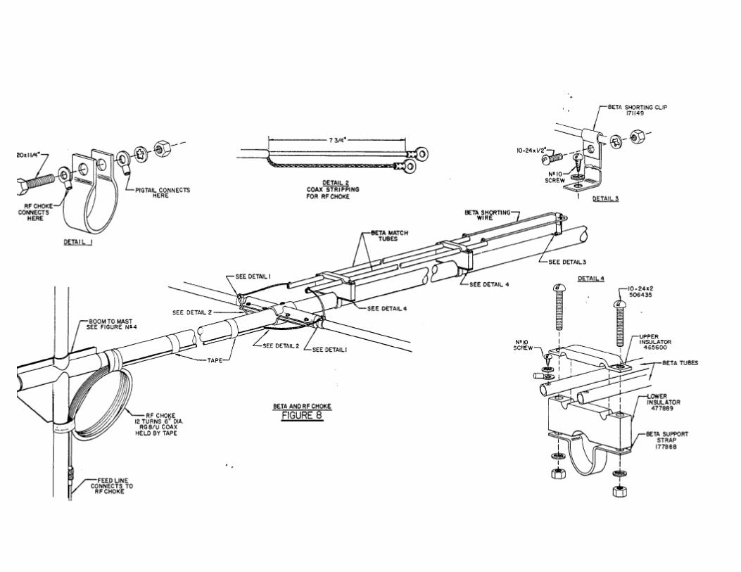
2-6 ASSEMBLY OF THE BETA MATCH
Select the Beta Match tubes (3/4 x 38 3/4"), Beta shorting wire (1/8" formed wire) and the Beta supporting insulators and clamps a s shown in Figure 8. Attach the shorting wire to the Beta tubes using the two #10 sheet metal screws and lockwashers. Assemble the Beta tubes on the boom as shown in Figure 8 using four 10-24 x 2" screw, nuts and lockwashers but do not tighten the screws at this time.
Select the Beta shorting clip and secure to the end of the Beta shorting wire using a 10-24 x 1/2" screw, nut and lockwasher. Attach the shorting clip to the boom using a #10 sheet metal_ screw and lockwasher. Now tighten all screws SECURELY.
2-7 ASSEMBLY OF THE 10 METER DIRECTOR
Select a set of small element-to-boom brackets and LOOSELY assemble on the boom 73" from the center of the Driven Element bracket to the center of the 10 meter Director bracket as shown in Figures 5 and 6.
Select the tubing bundle marked "10 Dir" and assemble on the boom in the same manner as you did the previous elements. Refer to Figures 5, 6 and 7. Make certain the 10 meter Director lies in the same plane as the other elements and carefully re-check the 73" dimension before tightening the bracket anchor screws SECURELY.
2-8 ASSEMBLY OF THE 15 METER DIRECTOR
Select the remaining set of small element-to-boom brackets and LOOSELY assemble on the boom 47 1/2" from the center of the 1.0 meter Director bracket to the center of the 15 meter Director bracket.
Page 13
2-8 (Continued)
Select the tubing bundle marked 1115 Dir" and assemble on the boom in the same manner as the previous elements. Refer to Figures 5, 6 and 7 for illustrations. Make certain the 15 meter Director lies in the same plane as the other elements and carefully re-check the 47 1/2" dimension before tightening the bracket anchor screws SECURELY.
2-9 ASSEMBLY OF THE 10-20 METER REFLECTOR
Select the remaining set of medium sized element-to-boom brackets and LOOSELY assemble on the boom. 39 1/2" from the center of the 15 meter Director bracket to the center of the 10-20 meter Director bracket.
Select the tubing bundle marked "10-20 Dir" and the 10 meter Director trap (marked 10 Dx) and assemble in the same manner as the previous elements. Refer to Figures 5, 6 and 7 for illustrations. Make certain the 10-20 meter Director lies in the same plane as the other elements and carefully re-check the 39 1/2" dimension before tightening the bracket anchor screws SECURELY.
Place a 7/1611 caplug on the end of each element and a 2" caplug on each end of the boom.
2-10 ATTACHMENT OF THE FEEDLINE AND RF CHOKE
Wind yourself an RF choke similar to the one shown in Figure 8. The choke must consist of 12 turns of RG-8/U coaxial cable with each turn having a 6" diameter. Allow enough cable at the end to reach from the mast to the Driven Element. Strip the coaxial cable as shown in Figure 8 Detail 2 and attach a solder lug (not supplied) to the center conductor and a solder lug to the braid,
This RF choke is necessary for the antenna to operate properly. However, it is recommended that you obtain a Hy-Gain balun Model BN-12 to use in place of the RF choke. The balun would allow the TH6-DX to operate with an efficiency far greater than with the "home-made" choke. The Model BN-12 is available at your local: Hy-Gain dealer.
Select the two 1 1/4" tubing clamps and install one on each side of the Driven Element placing them close to the insulators as shown in Figures 6 and 8.

Page 13
2-10 (Continued)
Attach the center conductor from the RF choke and a pigtail lead (wire with solder lug at each end) to one tubing clamp and the RF choke braid and the other pigtail lead to the opposite tubing clamp as shown in Figure 8, Detail 1. Connect the loose end of each pigtail lead to the Beta tube using a #10 sheet metal screw and lockwasher. Weatherproof the coax: connection using Pli-O-Bond, Neoprene or some similar substance. Also weatherproof the coaxial cable where the braid leaves the outer insulator to prevent water from entering the coax and ruining the first few feet of cable.
Tape the RF choke and feedline securely to the boom using waterproof tape. Later, when the antenna is mounted on the mast also tape the choke securely to the mast.
2-11 ASSEMBLY OF THE BOOM SUPPORT CABLE
Select the 2" ID boom support clamps (2 piece) and LOOSELY assemble on the boom approximately 94" from the boom-to-mast clamp as shown in Figure 9. Attach the boom support cable to the clamps using the thimbles and cable clips provided. Refer to Figure 9. Attach the turnbuckles to the opposite end of the cable as shown in the illustrations.
Now tape the cables near the boom-to-mast bracket so they will be handy later when the antenna has been mounted on the mast. Make certain the cable is above the elements.
Mount the antenna on your mast using one of the methods suggested in the beginning of this section. Allow approximately 36" of the mast to extend above the boom-to-mast bracket for attaching the boom-support cable. You will note that the boom-to-mast bracket has a 5/16" hole drilled in it for pinning to the mast. Once the antenna has been mounted and the boom support cables have been tightened to take all the sag out of the boom, drill a hole through the mast corresponding to the hole in the bracket. Then pin the bracket to the mast using the 5/16-18 x 3" bolt provided.
Assemble the 1 5/8" boom support clamp (2 piece) on the mast as shown in Figure 9. Extend the turnbuckle to its full length then attach to the clamp and tighten the clamp SECURELY. Tighten each turnbuckle until the boom lies in a level plane with no sag. Now pin the boom-to-mast bracket to the mast in the manner suggested above.

Page 13
2-12 LIGHTNING PROTECTION
For lightning protection you must ground your antenna supporting structure. A proper ground consists of a 1/2" x 8' ground rod driven into the ground as close as possible to the base of your tower or mast. Connect the rod to the tower or mast using a copper strap or 12 gauge copper or aluminum wire.
For total protection of your equipment it is highly recommended that you obtain a Hy-Gain Model LA-1 lightning arrestor. The Model LA-1 is available at your local Hy-Gain dealer.
THIS COMPLETES YOUR INSTALLATION OF THE TH6-DX. SIMPLY ATTACH YOUR FEEDLINE TO THE RF CHOKE AND HAPPY DX'ING.

Page 13
SECTION 3
PARTS LIST
PART NO. QTY DESCRIPTION COST EACH 112539 4 DE1 & D3-1,x'1 1/4 x 058 x 48" 3.14 113833 4 R2-1 & D2-1, 7/8x049x55" SWG 7/8 2.95 114729 2 D-2, 7/16x035x48" 2.74 114781 4 D2-3 & D3-3, 7/16x035x52" 2.77 115044 2 D-1, 7/8x049x53" Swg 7/16 2. 89 163764 6 Bracket #4, 7/8" Element-to-Boom 1.50 163166
9Bracket #5, 1 1/4" Element-to-Boom 1.50
165107 2 Bracket #6, Driven Element-to-Boo . 1.75 ' 171151 1 to Shorting Wire, 1/8" Diameter .45
171152 2 E-4, ' 7/16x035x28" 2.20 171153 2 R-3, 7/16x035x37" 2.60 171154 2 R2-3,7/16x035x39" 2.61 171155 4 D2-2 & R2-2, 5/8x035x26" Swg 7/16 2.20 171156`' 2 DE-3, 1x058x4" .80 171157 2 D3-2, 1 1/8x058x32 1/2" Swg 7/8 2.80 171158 2 %-DE-2, 1 1/8x058x42" Swg 7/8 2.98 171159 2 R-2, 1 1/8x058x 98" Swg 7/8 2.93 171166. 2 Boom Section, 2x049x69 1/2" Drl 4.75 178414 2 • Beta Tube, 3/4x035x38 3/4" -. 2.72
4645 2 Bracket, Boom-to-Mast 2.75 637562 2 Cable, Boom Support, 7/16" Dia 2.50 802099 1 Manual, . TH6-DX . 50 872091 2 * R-1,11/4x058x95 1/2" 6.90 872095 2 * Trap, 10 Meter Director 6.00 872097 1 *.Boom Section, 2x120x79 1/2, DrL Beta 9.90 872098 1 * Boom Section, 2x120x79 1/2" 9.90 878637 2 * Trap, 15 Meter Driven Element 6.00 878694-% 2 * Trap, 15 Meter Reflector 6. 0,0 878749 2 * Trap, 10 Meter Driven Element 6.00 878413 1 * Parts Package "A" 14.85 872096 1 * Parts Package "B" 7.98 872086 1 * Parts ,Package "C" 7.30

Page 13
Parts Pack "A" contains the following:
PART NO. QTY DESCRIPTION COST EACH 168680 6 Clamp, Compression, 1 1/4" .20 168682 10 Clamp, Compression, 1" .20 165361 4 Clamp, Compression, 3/4" .20 165583 8 Clamp, Compression, 5/8" .20 165123 4 Clamp, Compression, 1/2" .20 177888 2 Clamp, Beta Support .08 171149 1 Clip, Beta Shorting .05 168695 2 Clamp, 1 1/4" Tubing .12 384490 4 Clamp, Boom Support, 2" ID .tom • y
357874 2 Turnbuckle 2.14 356788 5 Thimble, .05 359769 8 Clamp, Cable .35 384495 2 Clamp, Boom Support, 1 5/8" ID .40
171148 4 Sleeve, Beta Shorting .05
Parts Pack "B" contains the following:
506245 4 Screw, 5/16-18 x 1 1/2" .08 506885 2 Screw, 5/16-18 x 1" .05 506520 4 Screw, 10-24 x 3/8" .03 505821 8 Screw, 10-24 x 7/16" .03 505671 4 Screw, 10-24 x 5/16" .03 506330 58 Screw, 1/4-20 x 3/4" .03 509160 2 Screw, 1/4-20 x 2 1/4" .05 506235 3 Screw, 5/16-18 x 3" .20 506435 4 Screw.,. 10-24 x 2" .05 506485 1 Screw, 10-24 x 1/2" .03 506305 2 Screw, 1/4-20 x 1 1/4" .05 548684 28 Screw, 1/4-20 x 1/2" Tpr Pt .03 516470 5 Screw, #10 x 1/2" Type A, Sheet
Metal .03
558685 28 Nut, 1/4-20 Square .02 555362 16 Nut, 10-24 Square .02 556960 62 Nut, 1/4-20 Hex .02 556945 9 Nut, 5/16-18 ilex .02 556970 5 Nut, 10-24 Hex .02 567125 26 Lockwasher, #10 .02 567110 62 Lockwasher, 1/4" .02 567075 9 Lockwasher, 5/16" .02 567085 4 Washer, Flat, 5/16" .02

Parts Pack "C" contains the following:
Page 13
PART NO. QTY DESCRIPTION COST EACH 455644 12 Caplug, 7/1611 .05 455625 2 Caplug, 2" .25 477889 2 Insulator, Beta Support, Bottom 1.00 4 51600 2 Insulator, Beta Support, Top .85 65833 2 Insulator, Driven Element .75
878561 2 *Pigtail Leads .25 878561 1 Electroseal .50
*Denotes Assemblies Prices and/or specifications subject to change without notice. 10/6/64fwa
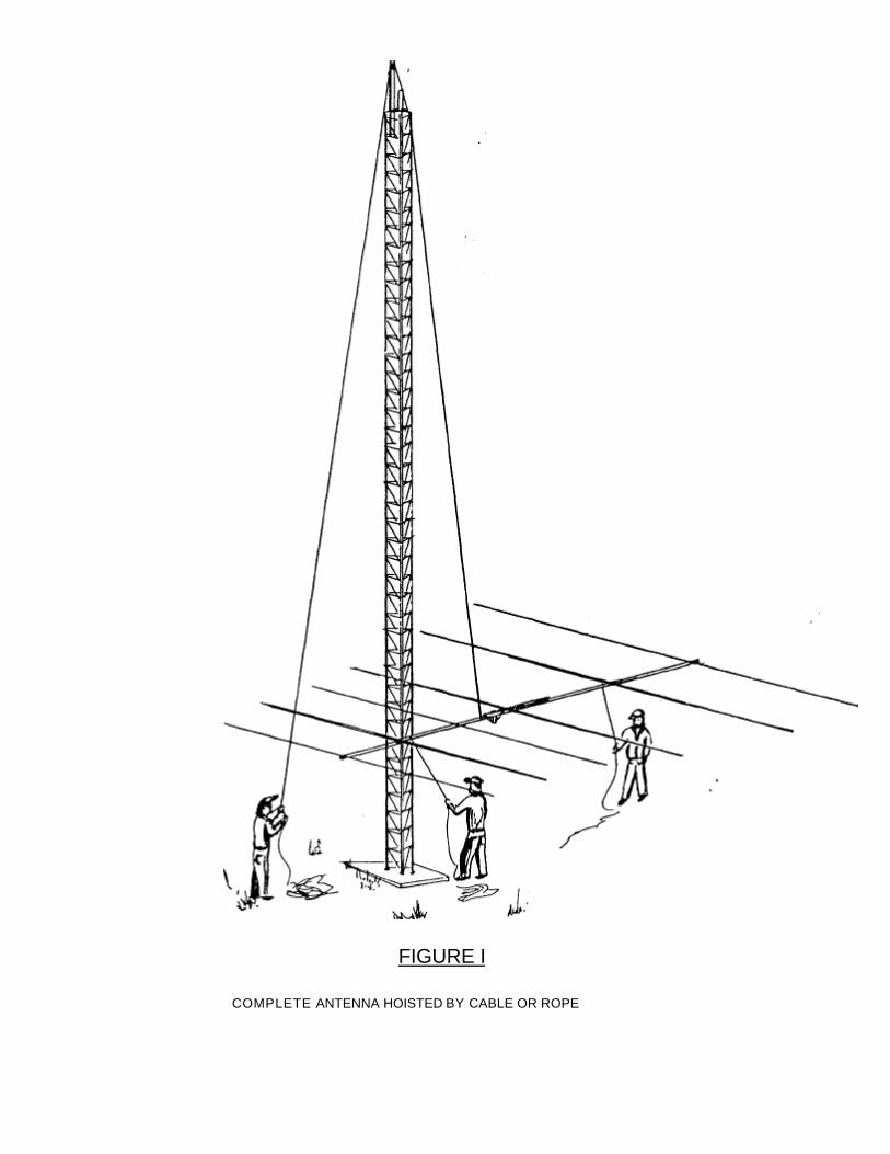
FIGURE I
COMPLETE ANTENNA HOISTED BY CABLE OR ROPE

COMPLETE ANTENNA USING GUYING FOR ERECTION