
Instruction Manual Fisher L2E Electric Level Controller
20
www.Fisher.com Fisher ™ L2e Electric Level Controller Contents Introduction 1 ................................. Scope of Manual 1 ............................. Description 2 ................................. Specifications 2 ............................... Educational Services 2 ......................... Installation 4 .................................. Attaching a Vertical Displacer 5 .................. Attaching a Horizontal Displacer 5 ............... Attaching the Sensor to the Vessel 5 ............. Electrical Connections 6 ........................ Seal Certification 10 ........................ L2e Initial Setup (Dry Displacer) 11 ............... L2e Zero and Span Adjustment (Wet Displacer) 11 .. Principle of Operation 12 ........................ Maintenance 14 ................................ Removing the Controller From the Sensor 14 ...... Installing Sensor Repair Kit (RL2SENSX012) 14 ..... Replacing the Complete Controller Assembly (RL2E0X00C22) 15 ................. Related Documents 16 .......................... Parts Ordering 16 ............................... Figure 1. Fisher L2e Electric Level Controller X0660 Introduction Scope of Manual This instruction manual includes installation, adjustment, maintenance, and parts ordering information for the Fisher L2e electric liquid level controller. Do not install, operate or maintain an L2e electric liquid level controller without being fully trained and qualified in valve, actuator, and accessory installation, operation, and maintenance. To avoid personal injury or property damage, it is important to carefully read, understand and follow all the contents of this manual, including all safety cautions and warnings. If you have any questions about these instructions, contact your Emerson sales office before proceeding. Instruction Manual D103531X012 L2e Controller March 2020
Transcript of Instruction Manual Fisher L2E Electric Level Controller

www.Fisher.com
Fisher™ L2e Electric Level Controller
ContentsIntroduction 1. . . . . . . . . . . . . . . . . . . . . . . . . . . . . . . . .
Scope of Manual 1. . . . . . . . . . . . . . . . . . . . . . . . . . . . .Description 2. . . . . . . . . . . . . . . . . . . . . . . . . . . . . . . . .Specifications 2. . . . . . . . . . . . . . . . . . . . . . . . . . . . . . .Educational Services 2. . . . . . . . . . . . . . . . . . . . . . . . .
Installation 4. . . . . . . . . . . . . . . . . . . . . . . . . . . . . . . . . .Attaching a Vertical Displacer 5. . . . . . . . . . . . . . . . . .Attaching a Horizontal Displacer 5. . . . . . . . . . . . . . .Attaching the Sensor to the Vessel 5. . . . . . . . . . . . .Electrical Connections 6. . . . . . . . . . . . . . . . . . . . . . . .
Seal Certification 10. . . . . . . . . . . . . . . . . . . . . . . .L2e Initial Setup (Dry Displacer) 11. . . . . . . . . . . . . . .L2e Zero and Span Adjustment (Wet Displacer) 11. .
Principle of Operation 12. . . . . . . . . . . . . . . . . . . . . . . .Maintenance 14. . . . . . . . . . . . . . . . . . . . . . . . . . . . . . . .
Removing the Controller From the Sensor 14. . . . . .Installing Sensor Repair Kit (RL2SENSX012) 14. . . . .Replacing the Complete Controller
Assembly (RL2E0X00C22) 15. . . . . . . . . . . . . . . . .Related Documents 16. . . . . . . . . . . . . . . . . . . . . . . . . .Parts Ordering 16. . . . . . . . . . . . . . . . . . . . . . . . . . . . . . .
Figure 1. Fisher L2e Electric Level Controller
X0660
Introduction
Scope of ManualThis instruction manual includes installation, adjustment, maintenance, and parts ordering information for the FisherL2e electric liquid level controller.
Do not install, operate or maintain an L2e electric liquid level controller without being fully trained andqualified in valve, actuator, and accessory installation, operation, and maintenance. To avoid personalinjury or property damage, it is important to carefully read, understand and follow all the contents ofthis manual, including all safety cautions and warnings. If you have any questions about theseinstructions, contact your Emerson sales office before proceeding.
Instruction ManualD103531X012
L2e ControllerMarch 2020
Instruction ManualD103531X012
L2e ControllerMarch 2020
2
DescriptionThe L2e electric liquid level differential gap on-off controller uses a displacement type sensor to detect liquid level orthe interface between two liquids of different specific gravities.
The L2e controls the lower trip point (zero) that closes the dump valve, allowing the vessel to fill to the upper trippoint. Once the upper trip point is reached, the dump valve opens to drain the fluid down to the zero or lower trippoint. The difference between the upper trip point and the zero or lower trip point is called differential gap or DG. TheL2e operates as a two position (on-off) controller.
The instrument uses an electronic switch (solid state relay) that provides one Normally Closed (NC) and one NormallyOpen (NO) contact. The electronic switch can be used to provide liquid monitoring or to provide differential gap (DG)control by operating an electrically-actuated valve.
Unless otherwise noted, all NACE references are to NACE MR01752002.
SpecificationsSpecifications for the controller and sensor are listed in table 1.
Educational ServicesFor information on available courses for L2e electric liquid level controllers, as well as a variety of other products,contact:
Emerson Automation SolutionsEducational Services - RegistrationPhone: 1-641-754-3771 or 1-800-338-8158E-mail: [email protected]/fishervalvetraining

Instruction ManualD103531X012
L2e ControllerMarch 2020
3
Table 1. Specifications
Available Configurations
Controller: Differential gap (DG) electric controlaction with intuitive Zero and Span Adjustments(refer to page 2 for differential gap description)Sensor: Displacertype liquid level sensor formounting to side of vessel
Input Signal
Type: Liquid level or liquidtoliquid interface
Level Change Required for Full Change in State ofOutput: 5.0 to 305 mm (0.2 to 12 inches)
Dynamic differential gap for the level in the vesseldepends on factors such as valve sizing, actuatorspeed, molecular weight, pressure, and temperatureof process fluids, input flow rate, and vessel size.
Specific Gravity Limits
Minimum SG: 0.15
Maximum SGPVC Displacer: 1.3SST Displacer: 1.1
Switch Contact Electrical Rating
1 amp resistive, 0.5 amp inductive/28 VDC; contactsare not polarity sensitive
Note: The easy-Drive™ actuator application draws7 mA through the L2e contacts @ 5 VDC
Power Requirements
Voltage: 9 - 30 VDC
Maximum Input Voltage Ripple: 400 mV
Current draw:Less than 15 mA steady stateLess than 500 mA peak startup or switching transient
Sensor to Vessel Connection
� 2 NPT threaded or � NPS 2 CL150 through 1500slipon flange connection(1)
Controller Connection
Electrical 1/2-14 NPT external conduit connectionwith 0.5 m (greater than 18 inches) of 18 AWG leadwires, located at the bottom of the case
Displacer Sizes
� 48 X 305 mm, 541 cm3 (17/8 X 12 inches, 33 in3)� 76 X 152 mm, 688 cm3 (3 X 6 inches, 42 in3)
Maximum Displacer Insertion Length(2), Horizontalor Vertical
1-7/8 x 12 Displacer with one 6-inch extension(optional use)3 x 6 Displacer with one 3-inch extension(optional use)
Displacer Material and Maximum MechanicalSensor Working Pressure(3)
PVC Displacer: Consistent with CL1500 pressuretemperature ratings per ASME B16.34 up tomaximum pressure of 258.5 bar (3750 psig).For PED (97/23/EC) maximum pressure limited to 200 bar (2900 psig).S31603 SST Displacer: CL600 pressure temperatureratings per ASME B16.34 up to maximum pressure of99.3 bar (1440 psig)
Note: For slipon flange connection, maximum sensorworking pressure must be consistent with the flangeratings
Operative Ambient Temperature Limits(3)
Controller: 40 to 85°C (40 to 185°F)
Operative Process Temperature Limits(3)
Sensor: � PVC Displacer: -18 to 71°C (0 to 160°F) � S31603 SST Displacer: 40 to 204°C (40 to 400°F)
Construction Materials
ControllerCase and Cover: Marine grade aluminumSwitch: Aluminum 6061TSwitch Body Internal O-ring: Fluorosilicone Rubber Span Levers: Stainless steelSprings: Stainless steel
SensorSensor Body: LCCORings: FluorocarbonPivot Assembly: Stainless steelDisplacer: � Polyvinylchloride (PVC) or � S31603 SSTSensor Spring: Stainless steel
-continued-
Instruction ManualD103531X012
L2e ControllerMarch 2020
4
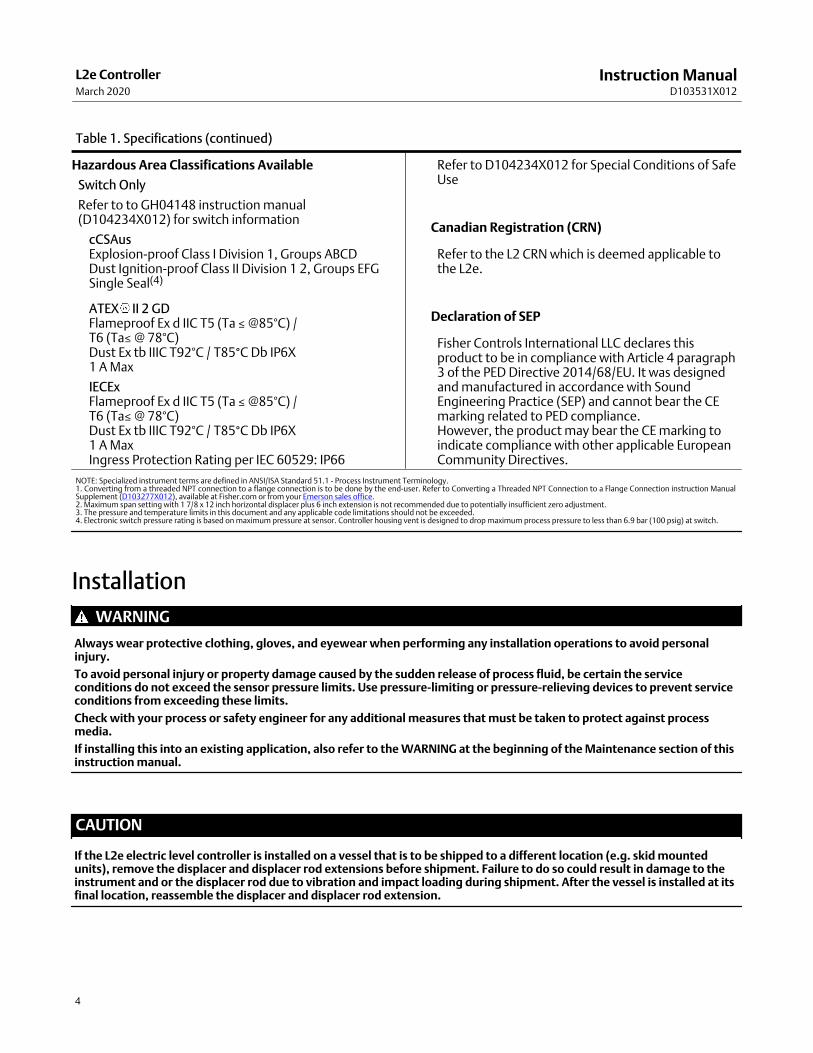
Table 1. Specifications (continued)
Hazardous Area Classifications Available
Switch Only
Refer to to GH04148 instruction manual(D104234X012) for switch information
cCSAusExplosion-proof Class I Division 1, Groups ABCDDust Ignition-proof Class II Division 1 2, Groups EFGSingle Seal(4)
ATEX II 2 GDFlameproof Ex d IIC T5 (Ta ≤ @85°C) / T6 (Ta≤ @ 78°C)Dust Ex tb IIIC T92°C / T85°C Db IP6X 1 A Max
IECExFlameproof Ex d IIC T5 (Ta ≤ @85°C) /T6 (Ta≤ @ 78°C)Dust Ex tb IIIC T92°C / T85°C Db IP6X 1 A MaxIngress Protection Rating per IEC 60529: IP66
Refer to D104234X012 for Special Conditions of SafeUse
Canadian Registration (CRN)
Refer to the L2 CRN which is deemed applicable tothe L2e.
Declaration of SEP
Fisher Controls International LLC declares thisproduct to be in compliance with Article 4 paragraph3 of the PED Directive 2014/68/EU. It was designedand manufactured in accordance with SoundEngineering Practice (SEP) and cannot bear the CEmarking related to PED compliance.However, the product may bear the CE marking toindicate compliance with other applicable EuropeanCommunity Directives.
NOTE: Specialized instrument terms are defined in ANSI/ISA Standard 51.1 Process Instrument Terminology.1. Converting from a threaded NPT connection to a flange connection is to be done by the end-user. Refer to Converting a Threaded NPT Connection to a Flange Connection instruction ManualSupplement (D103277X012), available at Fisher.com or from your Emerson sales office.2. Maximum span setting with 1 7/8 x 12 inch horizontal displacer plus 6 inch extension is not recommended due to potentially insufficient zero adjustment.3. The pressure and temperature limits in this document and any applicable code limitations should not be exceeded.4. Electronic switch pressure rating is based on maximum pressure at sensor. Controller housing vent is designed to drop maximum process pressure to less than 6.9 bar (100 psig) at switch.
Installation
WARNING
Always wear protective clothing, gloves, and eyewear when performing any installation operations to avoid personalinjury.
To avoid personal injury or property damage caused by the sudden release of process fluid, be certain the serviceconditions do not exceed the sensor pressure limits. Use pressurelimiting or pressurerelieving devices to prevent serviceconditions from exceeding these limits.
Check with your process or safety engineer for any additional measures that must be taken to protect against processmedia.
If installing this into an existing application, also refer to the WARNING at the beginning of the Maintenance section of thisinstruction manual.
CAUTION
If the L2e electric level controller is installed on a vessel that is to be shipped to a different location (e.g. skid mountedunits), remove the displacer and displacer rod extensions before shipment. Failure to do so could result in damage to theinstrument and or the displacer rod due to vibration and impact loading during shipment. After the vessel is installed at itsfinal location, reassemble the displacer and displacer rod extension.

Instruction ManualD103531X012
L2e ControllerMarch 2020
5
1. Be sure there are no obstructions inside the vessel that will interfere with displacer installation or operation.
2. Provide the appropriate connection in the vessel wall to match the sensor connection. Locate the vessel wallconnection such that the displacer will be at the desired control level.
Attaching a Vertical DisplacerRefer to figure 12 for part locations.
1. Thread jam nut (key 63) all the way onto the threaded portion of the universal joint assembly (key 69).
2. Thread the displacer (key 81) all the way onto the threaded portion of the universal joint assembly.
3. Tighten the jam nut against the displacer.
Attaching a Horizontal DisplacerRefer to figure 12 for part locations.
1. Thread the displacer (key 81) all the way onto the displacer rod (key 64) or extension (key 82) and tighten.
Attaching the Sensor to the VesselInsert the displacer end of the L2e sensor into the vessel connection and tighten enough to seal the threads. Ifnecessary, loosen or tighten slightly to obtain the horizontal orientation shown in figure 2. Make sure that thecontroller case is level.
CAUTION
The displacer rod (key 64) is not a handle. Grasp sensor body or controller housing to lift and carry to avoid internalcomponent damage.
Figure 2. Sensor Orientation
CORRECT CONTROLLER MOUNTINGHOLE ORIENTATION WHEN MOUNTED ON VESSEL
A6639
Instruction ManualD103531X012
L2e ControllerMarch 2020
6
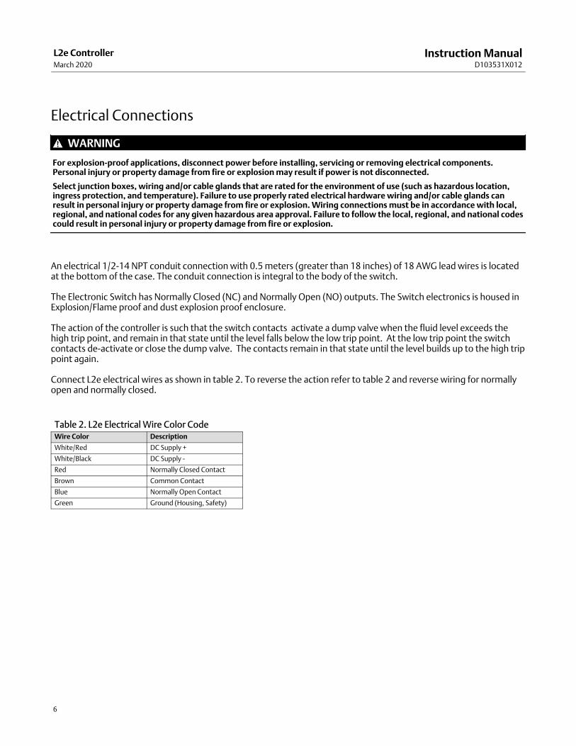
Electrical Connections
WARNING
For explosionproof applications, disconnect power before installing, servicing or removing electrical components.Personal injury or property damage from fire or explosion may result if power is not disconnected.
Select junction boxes, wiring and/or cable glands that are rated for the environment of use (such as hazardous location,ingress protection, and temperature). Failure to use properly rated electrical hardware wiring and/or cable glands canresult in personal injury or property damage from fire or explosion. Wiring connections must be in accordance with local,regional, and national codes for any given hazardous area approval. Failure to follow the local, regional, and national codescould result in personal injury or property damage from fire or explosion.
An electrical 1/2-14 NPT conduit connection with 0.5 meters (greater than 18 inches) of 18 AWG lead wires is locatedat the bottom of the case. The conduit connection is integral to the body of the switch.
The Electronic Switch has Normally Closed (NC) and Normally Open (NO) outputs. The Switch electronics is housed inExplosion/Flame proof and dust explosion proof enclosure.
The action of the controller is such that the switch contacts activate a dump valve when the fluid level exceeds thehigh trip point, and remain in that state until the level falls below the low trip point. At the low trip point the switchcontacts de-activate or close the dump valve. The contacts remain in that state until the level builds up to the high trippoint again.
Connect L2e electrical wires as shown in table 2. To reverse the action refer to table 2 and reverse wiring for normallyopen and normally closed.
Table 2. L2e Electrical Wire Color CodeWire Color Description
White/Red DC Supply +
White/Black DC Supply -
Red Normally Closed Contact
Brown Common Contact
Blue Normally Open Contact
Green Ground (Housing, Safety)

Instruction ManualD103531X012
L2e ControllerMarch 2020
7
Wiring ConfigurationsThere are two recommended wiring configurations depending on the preferred site solution and approach to electriclevel control; a direct connection to the easy-Drive actuator, shown in figure 3 or a direct connection to the easy-Driveactuator and a remote monitor (figure 4 and 5). In these examples, the L2e is wired using a common and separate N/Oor N/C contact. When implemented as suggested, these wiring configurations provide definitive level switch pointsand help reduce issues associated with single pole single throw contact switches, such as “bouncing” due to vibrationor sloshing liquids in a vessel.
Note
The wiring diagrams shown are for “sourcing”-type digital input cards.
“Sinking”-type digital input cards should not be wired to the L2e switch terminals in parallel with the easy-Drive input terminals asthey will be unintentionally and constantly activated by the easy-Drive “sourcing”-type input circuits.
If a PLC with sinking digital input cards is used, the easy-Drive input terminals need to be driven by a digital output card on that PLCand the PLC must control those digital outputs by its logic program after reading its digital inputs. This will introduce additionaldelay into the response to the input, modifying the dynamic differential gap achieved by the controller.
CLOSE
OPEN
Figure 3. Local Level Control with Direct Connection to easy-Drive Actuator without Remote Monitor
BROWN
BLUERED
12/24 VDCPOWER SUPPLY
easy-Drive ACTUATORPOWER AND CONTROL TERMINAL
X0661
1GREEN (GND)
1� CONNECT GREEN WIRE TO ACTUATOR GROUND (NOT SHOWN)2� OPEN CONTACT (2) MAY BE LABELED N.O. AND CLOSE CONTACT (3) MAY BE LABLED N.C.
2
W9795-4
REMOVE COVER TOACCESS POWER ANDCONTROL TERMINAL
easy-Drive ACTUATOR WITHFISHER D3 CONTROL VALVE
WHITE/RED
WHITE/BLACK

Instruction ManualD103531X012
L2e ControllerMarch 2020
8
BROWN
REDBLUE
WHITE/RED
BLU
E
BR
OW
N
DISCRETE INPUT CONFIGURED FOR DRY CONTACT CLOSURE EXTERNALLY POWERED
12/24 VDCPOWER SUPPLY
easy-Drive ACTUATORPOWER AND CONTROL TERMINAL
ROC809 DI MODULE
X0661
CLOSE
OPEN
1� CONNECT GREEN WIRE TO ACTUATOR GROUND (NOT SHOWN)2� OPEN CONTACT (2) MAY BE LABELED N.O. AND CLOSE CONTACT (3) MAY BE LABLED N.C.
1
2
GREEN (GND)
REMOVE COVER TOACCESS POWER ANDCONTROL TERMINAL
W9795-4
easy-Drive ACTUATOR WITHFISHER D3 CONTROL VALVE
Figure 4. Local Level Loop Control with Direct Connect to easy-Drive Actuatorwith ROC809 Remote Monitor
WHITE/BLACK
RE
D

Instruction ManualD103531X012
L2e ControllerMarch 2020
9
Figure 5. Local Level Loop Control with Direct Connect to easy-Drive Actuatorwith FloBoss 107 Remote Monitor
W9795-4
BROWN
REDBLUE
RE
D
BLU
E
BR
OW
N
DISCRETE INPUT CONFIGURED FOR DRY CONTACT CLOSURE EXTERNALLY POWERED
12/24 VDCPOWER SUPPLY
FloBoss 107 AI/DI MODULE ORFloBoss 107 DIs ON CPU MODULE'S OPTIONAL I/O ASSEMBLY
X0661
CLOSE
OPEN
1� CONNECT GREEN WIRE TO ACTUATOR GROUND (NOT SHOWN)2� OPEN CONTACT (2) MAY BE LABELED N.O. AND CLOSE CONTACT (3) MAY BE LABLED N.C.
1GREEN (GND)
2
REMOVE COVER TOACCESS POWER ANDCONTROL TERMINAL
easy-Drive ACTUATORPOWER AND CONTROL TERMINAL
easy-Drive ACTUATOR WITHFISHER D3 CONTROL VALVE
WHITE/BLACK
WHITE/RED

Instruction ManualD103531X012
L2e ControllerMarch 2020
10
Seal Certification
The L2e instrument is not dual-seal certified. However, the enclosure is not exposed to process pressure during normaloperation, and is vented, as shown in 6. The process seal is contained in the separate mechanical sensor which can beseparated from the L2e enclosure without disturbing the process connection. A process seal failure will result inprocess fluids being exhausted through the L2e enclosure vent, with an accompanying decrease in enclosure pressurefrom the operating process pressure. Thus annunciation of a process seal failure is provided. The switch component,which is separately sealed from the L2e main enclosure volume by a metal cap, is never exposed to full processpressure even in the event of process seal failure.
Figure 6. Schematic
PROCESS PRESSURE
VESSEL
INSTRUMENT ENCLOSURE
VENT
PROCESSMEDIA SEAL
Controller housing vent is designed to drop maximum process pressure to less than 6.9 bar (100 psig) at switch in event of primary seal failure
DETAIL
SENSOR
Certified Single Seal DeviceMaximum seal pressure: 6.9 bar (100 psig)Seal Temperature: 40 to 204°C (40 to 400°F)
SWITCH

Instruction ManualD103531X012
L2e ControllerMarch 2020
11
L2e Initial Setup (Dry Displacer)Refer to figure 7.
1. Apply power to the L2e Switch assembly.
2. Move Span to minimum setting.
3. If the switch is already in the state that opens the dump valve, skip to step 4. Otherwise, (e.g., lever B is resting onits travel stop), first move the plunger away from the switch by moving the Zero adjustment until the switch justchanges to the state required to open the dump valve.
4. Slowly bring the plunger towards the switch by moving the Zero adjustment until the switch changes to the staterequired to close the dump valve.
L2e Zero and Span Adjustment (Wet Displacer)After initial setup (dry displacer) is complete,
1. Enable process flow into the vessel.
2. Move Zero and Span Adjustment for desired liquid zero position and level DG.
3. Tighten the Zero Adjustment hex nut (key 5), shown in figure 10, to lock the Zero setting.
Figure 7. Initial Setup
ÂÂ
SPAN ADJUSTMENT
ZEROADJUSTMENT
SPAN ADJUSTMENT
ZERO ADJUSTMENT
CAUTION: FACTORY SET— DO NOT ADJUST —
MOVE
MOVE
LEVEL HEIGHT
LEVELDIFFERENTIAL GAP
INCREASE
DECREASE
RAISE
LOWER

Instruction ManualD103531X012
L2e ControllerMarch 2020
12
Principle of OperationThe operation of the L2e’s mechanical sensor is based on Archimedes’ Principle, which states that a body immersed ina liquid will be buoyed up by a force equal to the weight of the fluid being displaced. The net weight of the displacer inthe liquid is transmitted to the controller and amplified by the lever arm ratio. The amount of force amplification isincreased by adding extensions in the arm, and/or by mounting the displacer horizontally, since the effective length ofthe vessel side of the lever arm is the radial distance from the pivot to a vertical line through the center of gravity of thedisplacer. (Mounting the displacer horizontally distributes the total buoyancy change over a much smaller verticallevel change. It also introduces non-linearity, because the change in submerged volume of a horizontal cylinder ismuch higher for small level changes around the 50% point than it is near the top and bottom limits.)
Changes in the resultant force are transmitted through levers A and B to move the magnet (refer to figure 8 and 9). Asfluid level rises, the magnet moves away from the switch and vice versa. The lower switch point (at which the dumpvalve is to close) is set by balancing out the net force at that position with the zero-spring setting.
Figure 8. Principle of Operation Schematic
LEVER ARM
DISPLACER
PIVOT
ZEROSPRING
LEVER B
LEVER A
LEVER BRETURNSPRING
LEVER A PIVOT AND LEVER B TRAVEL STOP
SPANADJUSTMENT
LEVER BPIVOT
MAGNET
NON-CONTACTSWITCH
E1775
The magnet is attached to a plunger on lever B, which has a fixed return spring forcing the plunger toward theelectronic switch. The hysteresis between magnet positions that cause the electronic switch to change states is fixed.The magnet plunger is adjusted at the factory so that when lever B is on its travel stop, the switch contacts are in thestate required to close the dump valve, and the full hysteresis required to change to the state that will open the dumpvalve is available for utilization. Levers A and B are connected by a movable pivot so that the change in buoyant forcerequired to produce a given amount of movement between the magnet and the switch can be adjusted. This spanadjustment controls the amount of buoyancy change required to change the switch state, thus setting upper switchpoint and the static value of the differential gap.

Instruction ManualD103531X012
L2e ControllerMarch 2020
13
PROCESS INLET
PROCESS VESSEL
UPPER TRIP POINT
LOWER TRIP POINT
DIFFERENTIAL GAPSET BY SPAN ADJUSTMENT
OPENS AT UPPER TRIP POINTCLOSES AT LOWER TRIP POINT
DUMPDUMPVALVE
EasyDriveELECTRONICSWITCH
Figure 9. Fisher L2e Controller Operation
Figure 10. Fisher L2e Controller
SWITCH
SPAN ADJUSTMENT
LEVER B
GG10047w/Displacer Rod
PLUNGER FACTORY SET - DO NOT ADJUST
LEVER ACONTROLLER MOUNTINGSCREWS (KEY 24)
ZERO SPRING(KEY 7)
ZERO ADJUSTMENT
DISPLACERROD (KEY 64)
ZERO ADJUSTMENTHEX NUT (KEY 5)

Instruction ManualD103531X012
L2e ControllerMarch 2020
14
MaintenanceParts are subject to normal wear and must be inspected periodically and replaced as necessary. The frequency of partsinspection and replacement depends upon the severity of service conditions.
When inspection or repairs are required, disassemble only those parts necessary to accomplish the task.
WARNING
Always wear protective clothing, gloves, and eyewear when performing any maintenance operations to avoid personalinjury. To avoid personal injury or property damage caused by the release of pressure or process fluid, observe thefollowing before starting maintenance:
� Provide some temporary means of control for the process before taking the controller out of service.
� Provide a means of containing the process fluid before removing any measurement devices from the process.
� Vent any trapped process pressure.
� Check with your process or safety engineer for any additional measures that must be taken to protect against processmedia.
Removing the Controller From the SensorRefer to figure 9 for key number locations unless otherwise indicated.
1. Disconnect power from any electrical source.
2. Slide the hook end of the zero spring (key 7) over and off the controller end of the displacer rod (key 64).
3. Remove the four controller mounting screws (key 24), and pull the controller straight away from the sensor.
Installing Sensor Repair Kit (RL2SENSX012)Refer to figure 12 for key number locations unless otherwise indicated.
Disassembly1. Remove the controller from the sensor by following the procedure outlined in the previous section.
WARNING
To avoid personal injury or property damage from leaking process fluid relieve process pressure and drain the vessel beforeremoving the sensor from the vessel.
2. Remove the sensor from the vessel.
3. Unscrew the hex nut (key 67) and remove the spacer (key 66) and spring (key 68). After removing the spring,replace the spacer (key 66) and hex nut (key 67) on the displacer rod.
From the displacer end, pull the displacer rod away from the sensor connection (key 65) to pull the pivot base (key 73) loose from the sensor connection. Remove the hex nut (key 67) to permit removing the displacer rod, pivotbase, pivot body, and spacer from the sensor connection.

Instruction ManualD103531X012
L2e ControllerMarch 2020
15
4. Slide the pivot base (key 73), retaining ring (key 76), antiextrusion ring (key 75), and Oring (key 74) off thedisplacer rod. Remove the Oring (key 77) and backup ring (key 78) from the pivot base.
Assembly
WARNING
Improper assembly of the Orings, anti-extrusion ring, and backup ring could result in Oring extrusion and permit leakageof process fluids. To avoid personal injury or property damage from leaking process fluid, be sure the Orings,antiextrusion ring and backup ring are assembled in the order shown in figure 12.
1. Place the pivot body (key 72) on the displacer rod (key 64) so that it is positioned as shown in figure 12.
2. Apply silicone sealant (key 79) to the O-ring (key 74) and slide onto the displacer rod assembly (key 64) with theantiextrusion ring (key 75) and retaining ring (key 76). Be sure the Oring, antiextrusion ring, and retaining ring arein the order shown in figure 12. Slide the pivot base onto the displacer rod so that the knife edges of the pivot body (key 72) engage the slots in the pivot base (key 73).
3. Apply silicone sealant (key 79) to the O-ring (key 77) and install with the backup ring (key 78) into the groove on thepivot base (key 73). Be sure the backup ring is on the process pressure side of the Oring as shown in figure 12.
4. Insert the displacer rod (key 64) into the vessel side of the sensor connection (key 65).
5. The pivot base must seat in the slots cast in the sensor connection. These slots will be horizontal when the sensorconnection (key 65) is oriented as shown in figure 2.
6. To reduce the possibility of nicking the Oring key (77) on the pivot base, keep the displacer rod centered in thesensor connection as much as possible while pushing the pivot base into the sensor connection. Be sure the pivotbase seats in the slots cast in the sensor connection.
7. Slide the spring (key 68) and spacer (key 66) onto the displacer rod and secure with the hex nut (key 67). Fullytighten the hex nut (key 67).
8. Examine the sensor to ensure that the two pivot knife edges are seated in the pivot base slots.
9. Install the sensor on the vessel.
Replacing the Complete Controller Assembly (RL2E0X00C22)Refer to figure 10 for key number locations unless otherwise indicated.
1. Disconnect power from any electrical source.
2. Slide the hook end of the zero spring (key 7) over and off the controller end of the displacer rod (key 64)
3. Remove the four controller mounting screws (key 24) and pull the controller straight away from the sensor.
4. Install the new controller assembly on the sensor.
5. Mount with the four screws (key 24).
6. Slide the hook end of the zero spring (key 7) on the controller end of the displacer rod (key 64).
7. Complete signal wiring hookup to easy-Drive electric actuator.
8. Perform the Initial Setup (Dry Displacer) and Zero and Span Adjustment procedures found on page 11.
Instruction ManualD103531X012
L2e ControllerMarch 2020
16
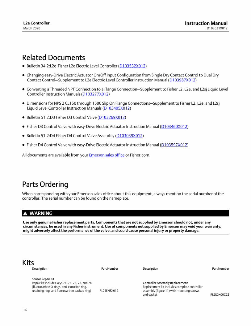
Related Documents� Bulletin 34.2:L2e Fisher L2e Electric Level Controller (D103532X012)
� Changing easy-Drive Electric Actuator On/Off Input Configuration from Single Dry Contact Control to Dual DryContact Control—Supplement to L2e Electric Level Controller Instruction Manual (D103987X012)
� Converting a Threaded NPT Connection to a Flange Connection—Supplement to Fisher L2, L2e, and L2sj Liquid LevelController Instruction Manuals (D103277X012)
� Dimensions for NPS 2 CL150 through 1500 Slip On Flange Connections—Supplement to Fisher L2, L2e, and L2sjLiquid Level Controller Instruction Manuals (D103405X012)
� Bulletin 51.2:D3 Fisher D3 Control Valve (D103269X012)
� Fisher D3 Control Valve with easy-Drive Electric Actuator Instruction Manual (D103460X012)
� Bulletin 51.2:D4 Fisher D4 Control Valve Assembly (D103039X012)
� Fisher D4 Control Valve with easy-Drive Electric Actuator Instruction Manual (D103597X012)
All documents are available from your Emerson sales office or Fisher.com.
Parts OrderingWhen corresponding with your Emerson sales office about this equipment, always mention the serial number of thecontroller. The serial number can be found on the nameplate.
WARNING
Use only genuine Fisher replacement parts. Components that are not supplied by Emerson should not, under anycircumstances, be used in any Fisher instrument. Use of components not supplied by Emerson may void your warranty,might adversely affect the performance of the valve, and could cause personal injury or property damage.
KitsDescription Part Number
Sensor Repair Kit
Repair kit includes keys 74, 75, 76, 77, and 78
(fluorocarbon O‐rings, anti‐extrusion ring,
retaining ring, and fluorocarbon backup ring) RL2SENSX012
Description Part Number
Controller Assembly Replacement
Replacement kit includes complete controller
assembly (figure 11) with mounting screws
and gasket RL2E0X00C22

Instruction ManualD103531X012
L2e ControllerMarch 2020
17
Figure 11. Fisher L2e Electric Level Controller Assembly
GG10047-K
Parts ListKey Description
Note
Contact your Emerson sales office for Part Ordering information.
Sensor (see figure 12)
63 Hex jam nut
64 Displacer rod
65 Sensor connection
66 Spacer
67 Hex jam nut
68 Conical spring
69 Universal Joint (vertical displacer only)
70 Nameplate
Key Description
71 Drive screwl
72 Knife pivot body
73 Knife pivot base)
Note
Keys 74, 75, 76, 77, and 78 are included in the Sensor Repair Kit.
74 O‐Ring
75 Anti‐extrusion ring
76 Retaining ring
77 O‐Ring
78 Backup ring
79 Sealant, silicone
(not furnished with sensor)
81 Displacer,
1‐7/8x12‐inches
3x6-inches
82 Extension
3 inches
6 inches
89 NACE Label

Instruction ManualD103531X012
L2e ControllerMarch 2020
18
Figure 12. Sensor
SECTION A-A
A
A
C C
B
VIEW B-BSCALE 2:1
SECTION C-CSCALE 2:1
� APPLY LUB/SEALANTGG12263-B

Instruction ManualD103531X012
L2e ControllerMarch 2020
19

Instruction ManualD103531X012
L2e ControllerMarch 2020
20
Emerson Automation Solutions Marshalltown, Iowa 50158 USASorocaba, 18087 BrazilCernay, 68700 FranceDubai, United Arab EmiratesSingapore 128461 Singapore
www.Fisher.com
The contents of this publication are presented for informational purposes only, and while every effort has been made to ensure their accuracy, they are notto be construed as warranties or guarantees, express or implied, regarding the products or services described herein or their use or applicability. All sales aregoverned by our terms and conditions, which are available upon request. We reserve the right to modify or improve the designs or specifications of suchproducts at any time without notice.
� 2013, 2020 Fisher Controls International LLC. All rights reserved.
Fisher and easy-Drive are marks owned by one of the companies in the Emerson Automation Solutions business unit of Emerson Electric Co. EmersonAutomation Solutions, Emerson, and the Emerson logo are trademarks and service marks of Emerson Electric Co. All other marks are the property of theirrespective owners.
Neither Emerson, Emerson Automation Solutions, nor any of their affiliated entities assumes responsibility for the selection, use or maintenanceof any product. Responsibility for proper selection, use, and maintenance of any product remains solely with the purchaser and end user.


