INSTRUCTION MANUAL - MacGregor · Fi-156c STORCH V2 INSTRUCTION MANUAL (Photo includes the optional...
13
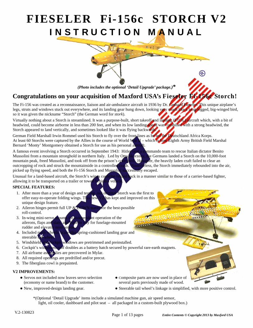
Page 1 of 13 pages FIESELER Fi-156c STORCH V2 INSTRUCTION MANUAL (Photo includes the optional ‘Detail Upgrade’ package.)* Congratulations on your acquisition of Maxford USA’s Fieseler Fi-156c Storch! The Fi-156 was created as a reconnaissance, liaison and air-ambulance aircraft in 1936 by Dr. Gerhard Fieseler. This unique airplane’s legs, struts and windows stuck out everywhere, and its landing gear hung down, looking very much like a long-legged, big-winged bird, so it was given the nickname “Storch” (the German word for stork). Virtually nothing about a Storch is streamlined. It was a purpose-built, short takeoff and landing (STOL) aircraft which, with a bit of headwind, could become airborne in less than 200 feet, and when its low landing speed was combined with a strong headwind, the Storch appeared to land vertically, and sometimes looked like it was flying backwards. German Field Marshall Irwin Rommel used his Storch to fly over the front lines as he led the Deutschland Africa Korps. At least 60 Storchs were captured by the Allies in the course of World War II – which is how Eighth Army British Field Marshal Bernard ‘Monty’ Montgomery obtained a Storch for use as his personal aircraft. A famous event involving a Storch occurred in September 1943: Hitler sent a commando team to rescue Italian dictator Benito Mussolini from a mountain stronghold in northern Italy. Led by Otto Skorzeny, the Germans landed a Storch on the 10,000-foot mountain peak, freed Mussolini, and took off from the prison’s courtyard. However, the heavily laden craft failed to clear an outcropping of rock and struck the mountainside in a controlled crash. Nonetheless, the Storch immediately rebounded into the air, picked up flying speed, and both the Fi-156 Storch and Mussolini successfully escaped. Unusual for a land-based aircraft, the Storch’s wings could be folded back in a manner similar to those of a carrier-based fighter, allowing it to be transported on a trailer or towed behind a vehicle. SPECIAL FEATURES: 1. After more than a year of design and testing, our original Storch was the first to offer easy-to-operate folding wings. This new V2 has kept and improved on this unique design feature. 2. Aileron hinges permit full UP & DOWN travel for the best-possible roll-control. 3. In-wing mini-servo mounts for independent operation of the ailerons, flaps and slats, and built-in tray for fuselage-mounted rudder and elevator mini servos. 4. Included main wheels, scale-like spring-cushioned landing gear and steerable tail wheel. 5. Windshield and cockpit windows are pretrimmed and preinstalled. 6. Cockpit’s windowed roof doubles as a battery hatch secured by powerful rare-earth magnets. 7. All airframe assemblies are precovered in Mylar. 8. All required openings are predrilled and/or precut. 9. The fiberglass cowl is prepainted. V2 IMPROVEMENTS: Servos not included now leaves servo selection Composite parts are now used in place of (economy or name brand) to the customer. several parts previously made of wood. New, improved-design landing gear. Steerable tail wheel’s linkage is simplified, with more positive control. *(Optional ‘Detail Upgrade’ items include a simulated machine gun, air speed sensor, light, oil cooler, dashboard and pilot seat – all packaged in a custom-built plywood box.) V.2-130823 Entire Contents © Copyright 2013 by Maxford USA
Transcript of INSTRUCTION MANUAL - MacGregor · Fi-156c STORCH V2 INSTRUCTION MANUAL (Photo includes the optional...
Page 1 of 13 pages
FIESELER Fi-156c STORCH V2 I N S T R U C T I O N M A N U A L
(Photo includes the optional ‘Detail Upgrade’ package.)*
Congratulations on your acquisition of Maxford USA’s Fieseler Fi-156c Storch! The Fi-156 was created as a reconnaissance, liaison and air-ambulance aircraft in 1936 by Dr. Gerhard Fieseler. This unique airplane’s legs, struts and windows stuck out everywhere, and its landing gear hung down, looking very much like a long-legged, big-winged bird, so it was given the nickname “Storch” (the German word for stork).
Virtually nothing about a Storch is streamlined. It was a purpose-built, short takeoff and landing (STOL) aircraft which, with a bit of headwind, could become airborne in less than 200 feet, and when its low landing speed was combined with a strong headwind, the Storch appeared to land vertically, and sometimes looked like it was flying backwards.
German Field Marshall Irwin Rommel used his Storch to fly over the front lines as he led the Deutschland Africa Korps. At least 60 Storchs were captured by the Allies in the course of World War II – which is how Eighth Army British Field Marshal Bernard ‘Monty’ Montgomery obtained a Storch for use as his personal aircraft.
A famous event involving a Storch occurred in September 1943: Hitler sent a commando team to rescue Italian dictator Benito Mussolini from a mountain stronghold in northern Italy. Led by Otto Skorzeny, the Germans landed a Storch on the 10,000-foot mountain peak, freed Mussolini, and took off from the prison’s courtyard. However, the heavily laden craft failed to clear an outcropping of rock and struck the mountainside in a controlled crash. Nonetheless, the Storch immediately rebounded into the air, picked up flying speed, and both the Fi-156 Storch and Mussolini successfully escaped.
Unusual for a land-based aircraft, the Storch’s wings could be folded back in a manner similar to those of a carrier-based fighter, allowing it to be transported on a trailer or towed behind a vehicle.
SPECIAL FEATURES:
1. After more than a year of design and testing, our original Storch was the first to offer easy-to-operate folding wings. This new V2 has kept and improved on this unique design feature.
2. Aileron hinges permit full UP & DOWN travel for the best-possible roll-control.
3. In-wing mini-servo mounts for independent operation of the ailerons, flaps and slats, and built-in tray for fuselage-mounted rudder and elevator mini servos.
4. Included main wheels, scale-like spring-cushioned landing gear and steerable tail wheel.
5. Windshield and cockpit windows are pretrimmed and preinstalled. 6. Cockpit’s windowed roof doubles as a battery hatch secured by powerful rare-earth magnets. 7. All airframe assemblies are precovered in Mylar. 8. All required openings are predrilled and/or precut. 9. The fiberglass cowl is prepainted.
V2 IMPROVEMENTS:
Servos not included now leaves servo selection Composite parts are now used in place of (economy or name brand) to the customer. several parts previously made of wood.
New, improved-design landing gear. Steerable tail wheel’s linkage is simplified, with more positive control.
*(Optional ‘Detail Upgrade’ items include a simulated machine gun, air speed sensor, light, oil cooler, dashboard and pilot seat – all packaged in a custom-built plywood box.)
V.2-130823 Entire Contents © Copyright 2013 by Maxford USA
Page 2 of 13 pages
TABLE OF CONTENTS Important safety precautions ............................... 2
Warranty, liability waiver, and return policy ....... 3
Specifications ...................................................... 3
Parts List .............................................................. 3
Assembly instructions .................................... 4
Setup and adjustments .................................. 12
Preparation for transport and field setup ...... 12
Preflight checks ............................................ 12
IMPORTANT SAFETY PRECAUTIONS TO PROTECT YOUR MODEL, YOURSELF & OTHERS
1. This product should not be considered a toy, but rather a sophisticated, working scale model that functions much like a full-scale airplane. Because of its performance capabilities, this product, if not assembled and operated correctly, could cause injury to you or spectators and damage to property. Maxford USA provides you with a high-quality, thoroughly tested model airplane kit with assembly instructions. However, the quality and capabilities of your finished model airplane depends on how you build it, and your safety depends on how you use and fly it. Any testing or flying of this model airplane is done entirely at your own risk.
2. Assemble the model airplane according to these instructions. We recommend that you do not alter or modify the model, as doing so may result in an unsafe or unworkable model. In a few cases the instructions may differ slightly from the photos; in those instances the written instructions should be considered as correct. If you have any question or concern about these instructions, before you proceed with assembly of this product, contact us at (562) 529-3988, Monday through Friday, except national holidays, between 9 AM to 5 PM Pacific time.
3. It is your responsibility to install the R/C system and other components in such a way that this model airplane passes all ground safety/range tests and that the power system and controls operate smoothly and correctly.
4. Recheck the operation of this model airplane before every flight to ensure that all equipment is still operating correctly and that the model has remained structurally sound. Also before every flight, check all clevises and other connectors; do not fly without replacing any that you find damaged or defective.
5. If you are not an experienced R/C pilot or have not flown this type of model before, we recommend that you get the assistance of an experienced R/C pilot.
6. Throughout the lifetime of this model, use only the Maxford USA-recommended or equivalent electric motor and a new or well-maintained R/C radio system and the Maxford USA-recommended or equivalent batteries.
7. LITHIUM BATTERY HANDLING & USAGE WARNING!! When using LiPo batteries, read the battery’s instruction sheet or on-line information. Failure to follow all instructions could result in permanent damage to the battery, its surroundings, and bodily harm! If you crash this model airplane, check for battery damage. Do NOT use or charge a damaged Li-Po battery.
ONLY use a Li-Po approved charger. (NEVER use a NiCd/NiMH charger!)
ALWAYS set the charger’s output to match the battery’s voltage and mAh ratings.
ALWAYS charge through the battery’s “charge” connector. (NEVER charge its “discharge” leads.)
ALWAYS charge in a fireproof location.
NEVER place on combustible materials or leave unattended during charge or discharge.
NEVER charge a LiPo battery in excess of 4.2V per cell.
NEVER discharge a LiPo battery below 2.5V per cell.
NEVER allow battery temp. to exceed 150° F (65° C).
NEVER charge at a current greater than 1C (for example, in the case of a 2100 mAh battery, that’s 2.1 amps).
NEVER trickle charge.
NEVER disassemble or modify pack wiring in any way nor puncture any of the battery’s cells.
KEEP BATTERIES OUT OF THE REACH OF CHILDREN
8. Read and follow warnings enclosed with your CA adhesive. Apply CA adhesive carefully – Excess drips or runs will leave unsightly residue and/or ‘smoky/cloudy areas’ on nearby surfaces.
9. For your consideration, some customers have told us they always glue some extra triangular-shaped balsa wood to reinforce the area where the plywood motor box attaches to the firewall on their 300W and larger electric-powered airplanes. (This may be a good idea!)
10. While this kit has been flight-tested to meet or exceed our rigid performance and reliability standards in normal use, if you plan to perform any high-stress flying or if you plan to install a larger motor than specified, you (the buyer or user of this product) are solely responsible for taking any and all necessary steps to reinforce the high-stress points and/or substitute hardware that is more suitable for such increased stresses.
11. This model may include some fiberglass and carbon-fiber reinforced plastic parts that might require some cutting or sanding. Fiberglass and carbon-fiber dust may cause eye, skin and respiratory tract irritation. If you ever grind, drill or sand such parts, always wear safety goggles, a particle mask and rubber gloves; never blow into such a part to remove fiberglass or carbon-fiber dust, as the dust may blow back into your face.
V.2-130823 Entire Contents © Copyright 2013 by Maxford USA
Page 3 of 13 pages
WARRANTY, LIABILITY WAIVER, AND RETURN POLICY Maxford USA guarantees this kit to be free of defects in material and workmanship at the time of purchase. All of our products have been inspected in our factory and are checked again when shipped from our warehouse. However, Maxford USA cannot directly control the materials you may use nor your final assembly process. Therefore, Maxford USA can NOT in any way guarantee the performance of your finished model airplane. Furthermore, in purchasing this product, you (the buyer or user of this product) exempt, waive, and relieve Maxford USA from all current or future liability for any personal injury, property damage, or wrongful death, and if you (the buyer or user of this product) are involved in any claim or suit, you will not sue Maxford USA or any of its representatives. If you do not fully accept the above liability and waiver, you may request a return merchandise authorization number (RMA#) as explained in item 2, below. If you think there is a missing part or any shipping damage, please read our after-sales service and return policy as outlined below. 1. Inspect your order upon delivery for any shipping damage or missing part. If you find a problem, you must contact us within 10
days from receipt of your purchase by calling (562) 529-3988, Monday through Friday, except holidays, between the hours of 9 AM and 5 PM Pacific time. During this telephone conversation, and with your support, we will determine how to resolve your concern. (Note: Maxford USA Li-Po batteries are sold without warranty and are not eligible for return or credit.)
2. To request an RMA#, call (562) 529-3988, Monday through Friday, except holidays, between the hours of 9 AM to 5 PM Pacific time. If we elect to issue you an RMA#, you must clearly mark this RMA# on the outside of the package. (No return or exchange will be authorized after 10 days from the date of your receipt of the product; any package delivered to us without a Maxford USA RMA# is subject to being returned to the sender, as received, with return postage payable upon delivery.) Returned merchandise must be in its original condition as received from Maxford USA, with no assembly or modification, in the original packing materials, complete with all manuals and accessories. Return shipping and insurance charges must be prepaid by you, the buyer.
3. Returned merchandise that is accepted by Maxford USA for credit is subject to a 10% to 20% restocking fee; the final amount will be determined by Maxford USA upon receipt and examination of the returned merchandise.
Return Address: Maxford USA Distribution, Inc. 15939 Illinois Ave. #B-C Paramount, CA 90723
(IMPORTANT: If issued by Maxford USA, print the RMA# on the package near the above address.)
SPECIFICATIONS* Wingspan ............................................ 63 inches
Wing Area ............................. 397 square inches
Length .................................................. 40 inches
Flying weight ............................ 2 pounds, 14 oz. Motor (not included) .............................................................. Brushless outrunner; 560 Watt; 1,000 RPM/V (Recommended: Uranus 35425 or equivalent)
Electronic speed control (not included) ........... Brushless, rated for use with a 3S-LiPo battery at 60 Amps. (Recommended: Uranus 60A or equivalent, with built-in 3A or greater BEC) Battery (not included) ................................................................ Lithium Polymer, 3S or 4S/2100mAh, 20C
Propeller (not included) ............................... 11x7 (or as recommended by the manufacturer of your motor)
Radio system (not included) ................................................... Minimum of 5 channels with six mini servos
*(All dimensions and weights are approximate; production parts may vary from prototype photos.)
PARTS LIST 1. Items you must supply to complete this model of the Fieseler Fi-156c Storch:
Electric motor, propeller, electronic speed control, LiPo battery and suitable LiPo battery charger.
5- and 30-minute epoxy, hot-melt glue, cyanoacrylate (CA) adhesive, and masking tape.
A few common hand tools such as long-nosed and diagonal or side-cutter pliers, etc.
Radio transmitter, receiver (with a minimum of five channels) and six mini-servos.
Depending on your selection of radio and servos, you may also need four servo extensions and two Y-harness cables (one set for the ailerons and another set for the flaps & slats).
V.2-130823 Entire Contents © Copyright 2013 by Maxford USA
2. Items included with this model of the Fieseler Fi-156c Storch: Precovered wing panels with fully functional flaps, slats and ailerons,
with all hinges, horns and linkages.
Precovered vertical and horizontal stabilizers, with rudder and elevator, precut hinge openings, and all hinges, horns, linkages and pushrods.
Fuselage precovered in yellow and grey Mylar with preinstalled rudder and elevator pushrod housings.
Composite wing rod and struts and all related hardware, including screws, bolts and nuts (except those normally supplied with a motor).
Steerable tail-wheel assembly.
Prepainted fiberglass cowl.
Canopy/battery hatch secured by rare-earth magnets.
Preformed spring-cushioned main landing gear and steerable tail wheel.
Adhesive-backed, stick-on marking sheets.
This illustrated instruction manual.
ASSEMBLY INSTRUCTIONS
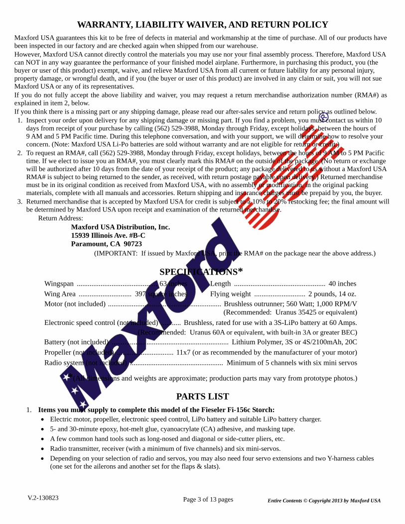
1. Insert the provided CA hinges into the precut aileron and flap hinge slots in the trailing edge of both wing panels; position each aileron’s and flap’s precut CA hinge slot onto their corresponding CA hinges.
2. Being careful that the inner end of each aileron does not bind against the outer edge of its mating flap, and being careful to leave enough clearance between the trailing edge of the wing and the front edge of each aileron and flap so full UP and DOWN travel is not restricted, permanently secure all aileron and flap hinges with thin CA. (Apply the CA adhesive carefully – Excess drips or runs will leave unsightly residue and/or ‘smoky’ or ‘cloudy’ areas on nearby surfaces.)
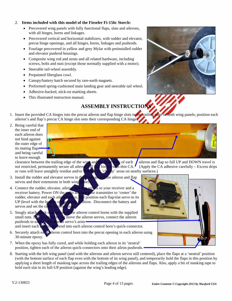
3. Install the rudder and elevator servos in the fuselage and the aileron and flap servos and their extensions in both wing panels.
4. Connect the rudder, elevator, aileron and flap servos to your receiver and a receiver battery. Power ON the radio and use your transmitter to ‘center’ the rudder, elevator and each aileron servo, and position each flap/slat servo to its UP (level with the bottom of the wing) position. Disconnect the battery and servos and set the radio system aside.
5. Snugly attach quick-connectors to the aileron control horns with the supplied small nuts. Being careful to not move the aileron servos, connect the aileron pushrods to each of the aileron servo’s arms and insert each aileron pushrod into each aileron control horn’s quick-connector.
6. Securely attach each aileron control horn into the precut opening in each aileron using 30-minute epoxy.
7. When the epoxy has fully cured, and while holding each aileron in its ‘neutral’ position, tighten each of the aileron quick-connectors onto their ailron pushrods.
8. Starting with the left wing panel (and with the ailerons and aileron servos still centered), place the flaps at a ‘neutral’ position (with the bottom surface of each flap even with the bottom of its wing panel), and temporarily hold the flaps in this position by applying a short length of masking tape across the trailing edges of the ailerons and flaps. Also, apply a bit of masking tape to hold each slat in its full-UP position (against the wing’s leading edge).
Page 4 of 13 pages V.2-130823 Entire Contents © Copyright 2013 by Maxford USA

Page 5 of 13 pages
Right side of fuselage is shown above.
Left side of fuselage is shown at the left.
9. Being careful to not move the flap/slat servo, connect a short pushrod to the flap/slat servo’s arm, and insert its other end into the quick-connector as shown below.
13. Being careful to not move the flap/slat servo, connect the right side’s three flap and slat pushrods as shown at the right. IMPORTANT: The LEFT and RIGHT wing panels’ flap & slat linkages are NOT simple “mirror images” of each other. Carefully configure each wing panel as shown in the photos above (left wing panel) and at the right (right wing panel).
14. Remove the masking tape from the right wing panel. On the underside of both wing panels, ‘vibration-proof’ each nut by applying a tiny ‘drop’ of hot-melt glue to the exposed threads at the end of every bolt and quick-connector, then set both wing panels aside.
15. Insert the prebent top ends of the main landing gear’s two(2) struts through the predrilled holes on each side of the fuselage. (These predrilled holes are located just behind the windshield, approx. 5/8 of an inch back of the wing’s leading edge.)
16. Inside the fuselage, tighten a wheel collar onto the top end of each landing gear’s strut.
17. Using round-topped wood screws and the predrilled holes on each side of the fuselage, secure the two landing gear strut assemblies to the fuselage’s anchor points. (Note: The the longer arm goes toward the nose.)
10. Tighten the quick-connector’s screw onto the flap and slat servo’s pushrod.
11. Install the remaining two(2) pushrods, one for the flap, the other for the slat, as shown at the left. Securely tighten each quick-connector, and remove the pieces of masking tape.
12. Just as you did for the left side’s wing panel, apply masking tape to temporarily hold the right-side wing panel’s flap in a ‘neutral’ (level) position and its slat fully ‘UP’ (against the leading edge of the wing).
Right side’s Flap
Right side’s Slat RIGHT side’s wing panel
Left side’s Slat Left side’s
Flap
LEFT side’s wing panel
Landing gear’s strut.
V.2-130823 Entire Contents © Copyright 2013 by Maxford USA
Page 6 of 13 pages
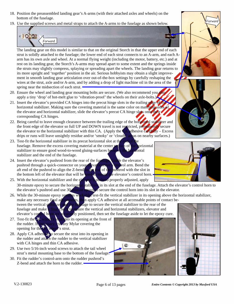
18. Position the preassembled landing gear’s A-arms (with their attached axles and wheels) on the bottom of the fuselage.
19. Use the supplied screws and metal straps to attach the A-arms to the fuselage as shown below.
The landing gear on this model is similar to that on the original Storch in that the upper end of each strut is solidly attached to the fuselage; the lower end of each strut connects to an A-arm, and each A-arm has its own axle and wheel. At a normal flying weight (including the motor, battery, etc.) and at rest on its landing gear, the Storch’s A-arms may spread apart to some extent and the springs inside the struts may slightly compress, splaying or spreading apart the wheels. The landing gear returns to its more upright and ‘together’ position in the air. Serious hobbyists may obtain a slight improve- ment in smooth landing gear articulation over out-of-the-box settings by carefully reshaping the wires at the strut, axle and/or A-arm, and by adding a drop of light machine oil in the area of the spring near the midsection of each strut.
20. Ensure the wheel and landing gear mounting bolts are secure. (We also recommend you also apply a tiny ‘drop’ of hot-melt glue to ‘vibration-proof’ the wheels on their axle-bolts.)
21. Insert the elevator’s provided CA hinges into the precut hinge slots in the trailing edge of the horizontal stabilizer. Making sure the covering material is the same color on matching sides of the elevator and horizontal stabilizer, slide the elevator’s precut CA hinge slots onto their corresponding CA hinges.
22. Being careful to leave enough clearance between the trailing edge of the horizontal stabilizer and the front edge of the elevator so full UP and DOWN travel is not restricted, permanently secure the elevator to the horizontal stabilizer with thin CA. (Apply the CA adhesive carefully – Excess drips or runs will leave unsightly residue and/or ‘smoky’ or ‘cloudy’ areas on nearby surfaces.)
23. Test-fit the horizontal stabilizer in its precut horizontal slot at the end of the fuselage. Remove the excess covering material at the center section of the horizontal stabilizer to ensure good wood-to-wood gluing-surfaces between the horizontal stabilizer and the end of the fuselage.
24. Insert the elevator’s pushrod from the rear of the fuselage. Guide the elevator’s pushrod through a quick-connector on your elevator servo’s control arm. Bend the aft end of the pushrod to align the Z-bend in the end of the pushrod with the slot in the bottom left of the elevator that will be used to mount the elevator’s control horn.
25. With the horizontal stabililzer and the elevator’s pushrod properly adjusted, apply 30-minute epoxy to secure the horizontal stabilizer in its slot at the end of the fuselage. Attach the elevator’s control horn to the elevator’s pushrod and use 30-minute epoxy to secure the control horn into its slot in the elevator.
26. While the 30-minute epoxy remains workable, test-fit the vertical stabilizer in its opening above the horizontal stabilizer, make any necessary final adjustments, then apply CA adhesive at all accessable points of contact be- tween the vertical stabilizer and the fuselage to secure the vertical stabilizer to the rear of the fuselage and make a final check to ensure the vertical and horizontal stabilizers, elevator and elevator’s control horn are accurately positioned, then set the fuselage aside to let the epoxy cure.
27. Test-fit the tail wheel’s strut into its opening at the front of the rudder. If necessary, cut any Mylar covering the opening for the tail wheel’s strut.
28. Apply CA adhesive to secure the strut into its opening in the rudder and attach the rudder to the vertical stabilizer with CA hinges and thin CA adhesive.
29. Use two 5/16-inch wood screws to attach the tail wheel strut’s metal mounting base to the bottom of the fuselage.
30. Fit the rudder’s control-arm onto the rudder pushrod’s Z-bend and attach the horn to the rudder.
Forward.
Forward.
V.2-130823 Entire Contents © Copyright 2013 by Maxford USA
Page 7 of 13 pages
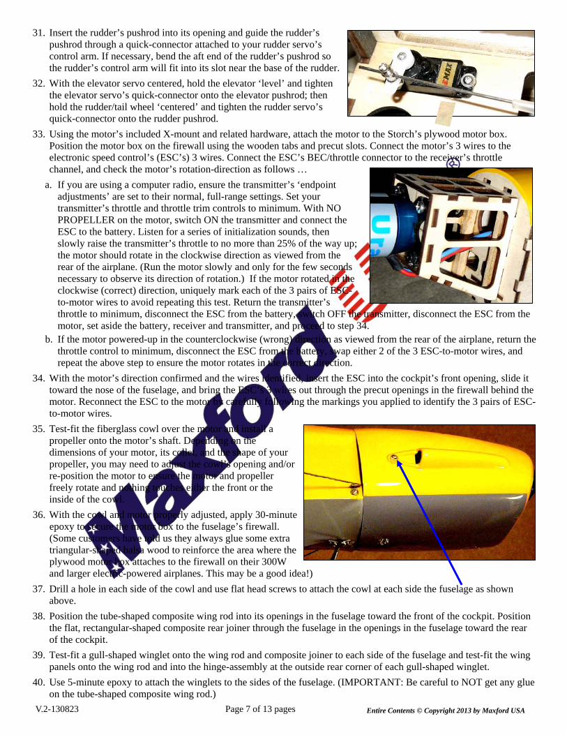
31. Insert the rudder’s pushrod into its opening and guide the rudder’s pushrod through a quick-connector attached to your rudder servo’s control arm. If necessary, bend the aft end of the rudder’s pushrod so the rudder’s control arm will fit into its slot near the base of the rudder.
32. With the elevator servo centered, hold the elevator ‘level’ and tighten the elevator servo’s quick-connector onto the elevator pushrod; then hold the rudder/tail wheel ‘centered’ and tighten the rudder servo’s quick-connector onto the rudder pushrod.
33. Using the motor’s included X-mount and related hardware, attach the motor to the Storch’s plywood motor box. Position the motor box on the firewall using the wooden tabs and precut slots. Connect the motor’s 3 wires to the electronic speed control’s (ESC’s) 3 wires. Connect the ESC’s BEC/throttle connector to the receiver’s throttle channel, and check the motor’s rotation-direction as follows …
a. If you are using a computer radio, ensure the transmitter’s ‘endpoint adjustments’ are set to their normal, full-range settings. Set your transmitter’s throttle and throttle trim controls to minimum. With NO PROPELLER on the motor, switch ON the transmitter and connect the ESC to the battery. Listen for a series of initialization sounds, then slowly raise the transmitter’s throttle to no more than 25% of the way up; the motor should rotate in the clockwise direction as viewed from the rear of the airplane. (Run the motor slowly and only for the few seconds necessary to observe its direction of rotation.) If the motor rotated in the clockwise (correct) direction, uniquely mark each of the 3 pairs of ESC-to-motor wires to avoid repeating this test. Return the transmitter’s throttle to minimum, disconnect the ESC from the battery, switch OFF the transmitter, disconnect the ESC from the motor, set aside the battery, receiver and transmitter, and proceed to step 34.
b. If the motor powered-up in the counterclockwise (wrong) direction as viewed from the rear of the airplane, return the throttle control to minimum, disconnect the ESC from the battery, swap either 2 of the 3 ESC-to-motor wires, and repeat the above step to ensure the motor rotates in the correct direction.
34. With the motor’s direction confirmed and the wires identified, insert the ESC into the cockpit’s front opening, slide it toward the nose of the fuselage, and bring the ESC’s 3 wires out through the precut openings in the firewall behind the motor. Reconnect the ESC to the motor by carefully following the markings you applied to identify the 3 pairs of ESC-to-motor wires.
35. Test-fit the fiberglass cowl over the motor and install a propeller onto the motor’s shaft. Depending on the dimensions of your motor, its collet, and the shape of your propeller, you may need to adjust the cowl’s opening and/or re-position the motor to ensure the motor and propeller freely rotate and nothing touches either the front or the inside of the cowl.
36. With the cowl and motor properly adjusted, apply 30-minute epoxy to secure the motor box to the fuselage’s firewall. (Some customers have told us they always glue some extra triangular-shaped balsa wood to reinforce the area where the plywood motor box attaches to the firewall on their 300W and larger electric-powered airplanes. This may be a good idea!)
37. Drill a hole in each side of the cowl and use flat head screws to attach the cowl at each side the fuselage as shown above.
38. Position the tube-shaped composite wing rod into its openings in the fuselage toward the front of the cockpit. Position the flat, rectangular-shaped composite rear joiner through the fuselage in the openings in the fuselage toward the rear of the cockpit.
39. Test-fit a gull-shaped winglet onto the wing rod and composite joiner to each side of the fuselage and test-fit the wing panels onto the wing rod and into the hinge-assembly at the outside rear corner of each gull-shaped winglet.
40. Use 5-minute epoxy to attach the winglets to the sides of the fuselage. (IMPORTANT: Be careful to NOT get any glue on the tube-shaped composite wing rod.)
V.2-130823 Entire Contents © Copyright 2013 by Maxford USA

41. Starting from either side of the fuselage, insert the composite wing rod through the two gull-shaped panels, centered midway through the fuselage. (IMPORTANT: Apply a dab of paint at the center of the wing rod to use to center the wing rod.)
42. Place the right wing panel onto the wing rod and slide it toward the fuselage. When the right wing panel’s root rib gets to within approx. 5 inches of the gull-shaped winglet, feed the connectors and leads from the aileron servo and the flap & slat servo into and through the gull-shaped winglet and into the fuselage. (Note: Direct the aileron and flap servo’s leads through your choice of the several openings in each wing panel’s root ribs; True to the original WWII Storch, this model offers you the option of folding wings; leave ‘slack’ in the aileron and flap servo leads inside the cabin for the wings to fold if you are assembling your Storch with folding wings.)
43. As you continue sliding the wing panel toward the fuselage, pull the servo leads inside the fuselage. As the wing panel’s root rib nears the gull-shaped winglet, align the wing panel’s hinge parts with their corresponding slotted openings at the rear of the gull-shaped winglet, then continue sliding the wing panel until it is fully seated against the gull-shaped panel.
44. Insert a supplied 1/2-inch-long machine bolt into the hole in the top of the gull-shaped winglet. Press the bolt fully through all of the wing panel’s metal hinge projections and the winglet’s slotted openings until the end of the bolt becomes visible at the bottom of the wing.
45. Position a supplied hex nut at the end of the bolt. Using a screwdriver, twist the bolt clockwise to draw the nut up into the hex-shaped opening in the bottom of the gull-shaped winglet.
46. Repeat steps 42 through 45 for the left wing panel and its hinge bolt. Note: The original Storch was designed as a reconnaissance, liaison and air-
ambulance aircraft; extensive flight-testing has shown that this model, when configured with folding wings, is capable of scale-like flying maneuvers; however, it is not intended for advanced, stressful aerobatic flying.
If being able to fold back the wings is not a feature you value or desire, immediately proceed to step 47. If you assemble your Storch with folding wings, the bolts that attach the left and right wing panels to their respective gull-
shaped winglets are the central part of each wing panel’s ‘hinge’ – And they must now be tested (and adjusted) as follows: a. Slide the composite wing rod left or right, into either wing panel, fold the wing panel back on the side that is now without
a wing rod, then remove the wing rod and fold the second wing panel back. b. If a hinge bolt restricts your ability to fold the wing, or if the hinge seems too loose, adjust as necessary for smooth,
slop-free folding operation; repeat this step until both hinges fold both directions smoothly and with no undue ‘play,’ c. Once the hinge bolts are properly adjusted, return the wing rod to its normal position, centered between the wing panels.
47. Insert and center the composite strut bracket through the precut openings in each side of the fuselage; secure the strut bracket to the floor of the fuselage with a small amount of 5-minute epoxy.
48. Position the Storch on a soft surface on its back. Note: If your Storch will have folding wings, your wing struts are non- functional (cosmetic only) to allow the wings to fold back for transport and to unfold for flight.
49. Use bolts and nuts to attach the preattached metal ends of the struts nearest the nose (as shown at the right, each of these struts is approx. 14 inches long) to the TOP side of the fuselage-mounted strut bracket on each side of the fuselage. Struts attached to the composite strut- mounting bracket, as viewed from the bottom-side of the fuselage.
LEFT side’s
wing panel
LEFT side’s flap
RIGHT side’s wing panel
RIGHT side’s flap Gull-shaped
winglet
Gull-shaped winglet
Page 8 of 13 pagesV.2-130823 Entire Contents © Copyright 2013 by Maxford USA
Install the shortest struts closest to the tail and the
longest struts closest to the
nose. Nose

Page 9 of 13 pages
50. Using the supplied bolts and nuts, attach the presecured metal ends of the REAR struts (each is approx. 13 1/2 inches long) to the BOTTOM side of the fuselage-mounted strut bracket on each side of the fuselage.
If you will not fold the wings, ‘snug’ each nut onto its bolt. If your Storch will have folding wings, leave these bolts and nuts barely
finger-tight, then apply a dab of hot-melt glue to secure the nuts onto their bolts.
51. Slide a supplied 3-inch long metal tube onto each of the free ends of the four composite struts.
If you will not fold the wings: Use the predrilled holes in the metal tubes and supplied screws to attach the outer end of each front strut to the ‘center’ of the three predrilled holes as shown below. Front strut attached to bottom of the wing from bolt in composite strut bracket. Back strut attached to bottom of the wing.
If you will not fold the wings: Apply CA to secure the screws and their struts to the wing and each strut within its metal tube.
If your Storch will have folding wings: Apply a dab of petroleum jelly to the metal end of each strut where it touches the wing to act as a lubricant and protection from glue; then, apply a small amount of thin CA adhesive to harden the predrilled holes in the wing, and use the metal tubes and supplied screws to attach the outer end of each strut to the predrilled hole in the wing as shown above, but leave these screws loosely finger-tight.
52. Apply a small ‘dot’ of hot-melt glue to secure and ‘vibration-proof’ … a. The heads of the hinge bolts at the top of each wing panel and the exposed threads
below the hinge-bolt’s nut at the lower surface of each wing panel. b. The head of each bolt, nut
and screw associated with each of the four wing struts, and the exposed threads below the four strut bracket bolts (as shown in the two photos to the right on this page).
53. Use a ‘dot’ of hot-melt glue to attach the diagonal braces at each side of the vertical and above the horizontal stabilizer.
NNeeww ccoommppoossiittee
ssttrruutt bbrraacckkeett
V.2-130823 Entire Contents © Copyright 2013 by Maxford USA
Nose
Page 10 of 13 pages
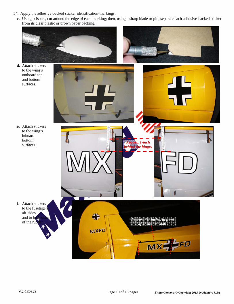
54. Apply the adhesive-backed sticker identification-markings: c. Using scissors, cut around the edge of each marking; then, using a sharp blade or pin, separate each adhesive-backed sticker
from its clear plastic or brown paper backing.
d. Attach stickers to the wing’s outboard top and bottom surfaces.
e. Attach stickers to the wing’s inboard bottom surfaces.
f. Attach stickers to the fuselage’s aft-sides and to both sides of the rudder.
Approx. 1-inch behind the hinges
Approx. 4¾-inches in front of horizontal stab.
V.2-130823 Entire Contents © Copyright 2013 by Maxford USA

Page 11 of 13 pages
g. Attach stickers to the fuselage’s forward-sides near the cabin.
55. Install the optional ‘Detail Upgrade’ items using CA adhesive and the predrilled holes or other supplied mounting hardware:
a. Simulated AIR SPEED SENSOR and LIGHT: Use the predrilled holes near the strut anchors and CA adhesive.
b. Simulated Oil Cooler: Use CA adhesive, the predrilled hole just-forward of the front A-frame attachment point, and the hole located approx. 3/4-inch forward of the bottom-back edge of the fiberglass cowl cowl (cut an opening in the bottom of the cowl to expose the more forward predrilled hole).
c. Simulated Machine Gun: Make a keyhole- shaped opening in the rear of the canopy; using the provided metal strap and screws, mount the machine gun to the predrilled holes at the bottom-rear of the canopy.
d. Dashboard and Pilot Seat: Secure the dashboard with CA adhesive or fasten it with the provided wood screws; the pilot seat attaches to your LiPo battery with the supplied hook-and-loop material.
WARNING: If you use the seat to help ‘handle’ your battery, be careful to not apply too much force to the seat.
LLiippoo bbaatttteerryy
V.2-130823 Entire Contents © Copyright 2013 by Maxford USA
Page 12 of 13 pages
Congratulations! Assembly is finished. SETUP AND ADJUSTMENTS
1. Set the Storch’s center of gravity (CG) at the composite wing rod. If necessary, reposition the LiPo battery and/or add weight to the nose or tail to ensure the CG is correct.
2. Check the heat-shrink covering material’s joints and surfaces. If necessary, carefully use a dedicated covering-material iron and heat gun to secure the edges and to tighten any loosened areas. Re-check and re-tighten from time to time.
3. Check/adjust servo centering, direction and end-point adjustments. When you pull the right stick toward you, the elevator should deflect upwards; push the right stick to the right and the right aileron should deflect upwards and the left aileron should deflect downwards; push the left stick left and the rudder should deflect to the left as viewed from the rear of the fuselage, and with your transmitter’s flaps control fully UP, the bottom surface of the flaps should be even with the bottom of the wing (and in line with the centered ailerons) and the slats should be fully retracted up and back against the leading edge of the wing.
4. If you are using a Computer Radio: For initial flights set all linkages for near-max. possible deflections; then, soften the aileron’s and elevator’s control throws by selecting 60% or more exponential (use 30% exponential for the rudder). Initial settings if you are using a Non-Computer Radio: Low rates High rates
Ailerons ................................ +15 degrees (+1/2 inch) .............. +20 degrees (+5/8 inches) Elevator ............................. +15 degrees (+1 1/8 inches) ......... +20 degrees (+1 1/4 inches) Rudder ............................... +15 degrees (+1 1/8 inches) ......... +20 degrees (+1 5/8 inches) Flaps (coupled to Slats) .......... 0 degrees ‘UP’ to approx. 20 degrees (3/4 inch) of ‘DOWN’
5. Trim adjustments: The ailerons and rudder will probably require no adjustments (you will probably be able to leave them centered, as assembled); however, be prepared to set the elevator trim depending on how slow or fast you fly, and at what setting you have the flaps & slats. For example, if you fly at slow, scale-looking air speeds, your Storch’s elevator will probably require a bit of up-trim, and it will need some down-trim when the flaps & slats are lowered. Review your radio’s instruction manual if you require assistance with any radio-related questions such as servo adjustments and/or flap-to-elevator mixing.
PREPARATION FOR TRANSPORT AND FIELD SETUP 1. This model of the Storch offers folding wings, like on the original Fi-156c. To fold the Storch’s wings back:
1) Lift off the roof of the cockpit. 2) Slide the composite wing rod left or right, into either wing panel. 3) Fold the wing panel back on the side that is now without a wing rod, then remove the wing rod and fold the
second wing panel back.
2. To restore the Storch’s wings to their normal, flying position, simply reverse the above procedure. IMPORTANT: Always center the composite wing rod between the two wing panels before flight.
PRE-FLIGHT CHECKS 1. Double-check the security of the propeller and motor mounting box on the firewall.
2. Make certain all screws, bolts and other mechanical and electrical connections remain secure.
3. Be certain the composite wing rod is centered between the two wing panels. (We recommend you use some masking or clear plastic tape to keep it from inadvertently sliding to one side or the other.)
4. Double-check the control directions and smooth functioning of throttle, ailerons, elevator, rudder, flaps and slats.
5. As with all radio-controlled model airplanes, this model must pass the radio range ground check recommended by your radio’s manufacturer, or you may not fly safely.
6. As a safety precaution, get into the habit of moving your transmitter’s throttle control to minimum before turning ON your transmitter and before connecting your Storch’s LiPo battery.
REMINDER: AN IMPORTANT NOTICE TO OUR CUSTOMERS …
T H I S P R O D U C T I S N O T A T O Y !
Because of its performance capabilities, this product, if not assembled and operated correctly, could cause injury to you or spectators and damage to property. Maxford USA provides you with a high-quality, thoroughly tested model airplane kit with assembly instructions. However, the quality and capabilities of your finished model airplane depends on how you build it, and your safety depends on how you use and fly it. Any testing or flying of this model airplane is done entirely at your own risk.
V.2-130823 Entire Contents © Copyright 2013 by Maxford USA

Manufactured by - Maxford USA RC Model Mfg, Inc. 15939 Illinois Avenue #B-C Paramount, CA 90723
Distributed by - Maxford USA Distribution, Inc. 15939 Illinois Avenue #B-C Paramount, CA 90723
Telephone (voice) ............................ (562) 529-3988 FAX ................................................ (562) 529-6988 Toll free (orders only) .................... (866) 706-8288 Web site ................... http://www.maxfordusa.com
Order replacement parts, servos, batteries, gas engines, brushless motors, electronic speed controls, and a wide variety of other high-quality RC hobby items online at
http://www.maxfordusa.com
Maxford USA RC Model Mfg., Inc. is a rapidly growing importer and distributor of radio-controlled model airplanes.
Our mission is to provide better RC products and services for our customers.
To help us offer quality RC models at competitive prices, 99% of our products are imported directly from the manufacturer’s factories.
Our Paramount, California showroom is open to the public from 10 AM to 5 PM Monday through Friday, except national holidays.
All orders from retail customers are shipped from our Paramount, California warehouse.
We also sell directly to brick-and-mortar hobby shops. To apply to become authorized to sell Maxford USA’s extensive line of RC products, download a Dealer Application from our Website; then Fax the completed form to us at (562) 529-6988.
Most dealer orders are shipped from our Paramount, California warehouse; however, to minimize freight and handling costs, we can arrange for large dealer orders to be drop-shipped from our factories directly to your store(s) or warehouse(s).
V.2-130823 Page 13 of 13 pages Entire Contents © Copyright 2013 by Maxford USA