Instruction Manual Digital Force Gage - AIKOH · -1- Safety Precautions The precautions...
20
(IMPORT & EXPORT DEPT.) OSAKA 15-7, 2-Chome, Hishie, Higashi-Osaka city, Osaka TEL (072)966-9011 FAX (072)966-9017 TOKYO 14-1, 5-Chome, ND bldg.,7F, Ueno, Taito-ku, Tokyo TEL ( 03 ) 5807-6434 FAX ( 03 ) 3834-2098 NAGOYA 210, 2-Chome, Sakuta, Nagakute city, Aichi TEL ( 0561 ) 64-2331 FAX ( 0561 ) 64-2332 OSAKA 15-7, 2-Chome, Hishie, Higashi-Osaka city, Osaka TEL ( 072 ) 966-9011 FAX ( 072 ) 966-9017 Instruction Manual Please read this instruction manual thoroughly before using the gage for the first time. This manual is very important when using the product. Keep it near the product in such a way that it can be referred to at any time necessary. This instruction manual covers both Model RZ Series and Model RZ-T Series. Digital Force Gage Model RZ Series
Transcript of Instruction Manual Digital Force Gage - AIKOH · -1- Safety Precautions The precautions...

(IMPORT & EXPORT DEPT.)OSAKA 15-7, 2-Chome, Hishie, Higashi-Osaka city, Osaka TEL (072)966-9011 FAX (072)966-9017
TOKYO 14-1, 5-Chome, ND bldg.,7F, Ueno, Taito-ku, Tokyo TEL (03)5807-6434 FAX (03)3834-2098NAGOYA 210, 2-Chome, Sakuta, Nagakute city, Aichi TEL (0561)64-2331 FAX (0561)64-2332OSAKA 15-7, 2-Chome, Hishie, Higashi-Osaka city, Osaka TEL (072)966-9011 FAX (072)966-9017
Instruction Manual
Please read this instruction manual thoroughly before using the gage for the first time.This manual is very important when using the product. Keep it near the product in such a way that it can be referred to at any time necessary.
This instruction manual covers both Model RZ Series andModel RZ-T Series.
Digital Force Gage
Model RZ Series

Table of Contents
1. Safety Precautions ……………………………………………1~3
2. Checking the Contents of the Package …………………4
3. Nomenclature ……………………………………………………5
4. Description of the Display ……………………………………6~7
5. Prior to Use ………………………………………………………8
6. Setting of Each Mode …………………………………………9~10
7. Flow of Mode Screen Selection ……………………………11
7-1. Setting of the comparator function …………………12
7-2. Concept of the upper limit value and lower limit value ……13
7-3. Setting of the stand control function ………………14
7-4. Precautions for installation on the electric test stand…… 15
7-5. Changing the screen display direction………………16
7-6. Using analog outputs ……………………………………17
7-7. Minimizing battery consumption for efficient use……17
7-8. Automatic zero resetting ………………………………18
7-9. Using the external zero resetting function…………18
7-10. Changing over between 3 units …………………19
8. Measurement 1
Measurement by use of the memory function ………20~22
Measurement 2
Measurement by use of the external contact hold ……23~ 24
Measurement 3
Connector mating/unmating measurement……………25
9. Force Calibration Procedure …………………………………26~28
10. Input/Output………………………………………………………29
10-1. Optional cable …………………………………………30~33
11.Specifications and External View ……………………………34
12. Warranty ……………………………………………………………35
-1-
Safety PrecautionsThe precautions presented below are very important for safety and must be observed strictly. The symbols and their meanings are as follows.
DANGER
Do not charge the gage longer than 24 hours.
Do not use an adapter or cable other than the included AC adapter and dedicated cable for charging.
The electronic circuit or other parts may be damaged.Such a practice may cause fire or electric shock.
Charging will be completed in about 4.5 hours.Charging longer than 24 hours will cause the body to become very hot and depending on situations, may break the incorporated batteries to cause fire.
Indicates that it is highly possible that the user will suffer serious injury or loss of life or indicates the possibility of serious consequences depending on situations due to the structure and characteristics of the product if the product is not used properly.
DANGER・・・・
Indicates the possibility that the user may suffer serious injury or loss of life if the product is not used properly.
WARNING・・・
Indicates the possibility of minor personal injury if the product is not used properly.CAUTION・・・
- 2-
Make sure that the object being measured will not fly off.
Do not use a damaged hook or deformed hook.
The hook may be broken or slip out of your hand to cause injury. Or the object being measured may fall to cause serious injury.
Be sure to insert the AC adapter to the receptacle fully.
Loose connection may cause a short circuit which can result in electric shock or fire.
When performing measurement which will destroy or cut an object to measure, wear equipment to protect yourself from broken pieces hitting your eyes or body.
WARNING
Do not plug or unplug the AC adapter with a wet hand.
You may suffer electric shock.
Do not hold the cord of the AC adapter to unplug it.
The cord may be broken to cause electric shock.
Never disassemble, repair or modify the gage.
Such a practice may result in malfunction to cause personal injury.
CAUTION
-3-
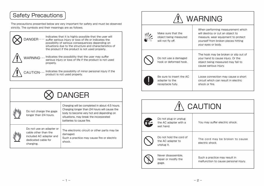
Do not apply a force exceeding the rated capacity.
The force sensor may be broken. Application of a larger force may break the body case or internal components to cause accidents.
Do not use or store the gage in the environment described on the right side:
・An environment where the gage may be exposed to water.・An environment where condensation may occur.・A dusty environment.・An environment where the gage may be exposed to oil or chemicals.
Use the gage within its working temperature range (0 to +40℃).
The use of the gage outside the working temperature range may cause malfunction. The working humidity range is 20% to 60% RH.
Make sure that mounting screws are of correct length.
Do not apply a force to the measuring shaft in a bending or torsional direction.
When mounting the gage, select such mounting screws that will not enter the body more than 6 mm. The use of a screw longer than this may damage the body case.
CAUTION
A force in bending directionA force in torsional direction
- 4-
Checking the Contents of the Package
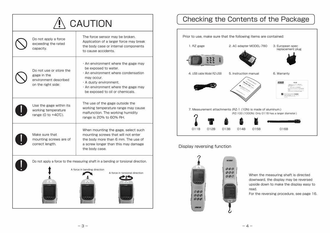
Prior to use, make sure that the following items are contained:
Display reversing function
When the measuring shaft is directed downward, the display may be reversed upside down to make the display easy to read.For the reversing procedure, see page 16.
1. RZ gage
(RZ-100 (1000N): Only 011B has a larger diameter.)7. Measurement attachments (RZ-1 (10N) is made of aluminum.)
011B 012B 013B 014B 015B 016B
2. AC adapter MODEL-780 3. European spec replacement plug
5. Instruction manual 6. Warranty4. USB cable Model RZ-USB
Instruction Manual
Please read this instruction manual
thoroughly before using the gage for
the first time.
This manual is very important when using the product.
Keep it near the product in such a way that it can be
referred to at any time necessary.
This instruction manual covers both Model RZ Series and
Model RZ-T Series.Digital Force Gage
Model RZ Series

-5-
Nomenclature
Description of the component devices
Comparator judgment LED
Power ON/OFF
ENT
FUNC
PRT
Printer output connector
I/O connector USB connector
MEMO
ZERO
PEAKTRACK
Measuring shaftDisplay
A force is detected by this part.Do not apply a force exceeding the allowable range to the measuring shaft, as it may cause the gage to fail.
Shows the user setting mode and measurement results.
Used to turn the power on and off.
Used to select a user setting mode and make setting.
Used to enter the user setting mode or return to the measurement screen from the user setting mode.
“P” shown lit or flashing in the display indicates the peak mode. When it is not shown, the mode is the track mode and the display constantly shows the value of a force applied to the measuring shaft.
Used to reset the indicated value to zero.
Used to output the indicated value to a printer.The gage must be connected to a printer with an optional cable in advance.
Each time the key is pressed, the indicated value will be stored in the memory.
Normally this is used to change the units of measurement.
Used to change the mode No. in the user setting mode.
When the gage is connected to a Digimatic Mini Processor DP-1VR or Liner Thermal Printer BL2-58SNWJC with an optional cable, measured values can be printed.
Connect the included AC adapter MODEL-780 and USB cable Model RZ-USB to charge the gage. Also by using the USB cable Model RZ-USB, the gage may be connected to a PC to send and manage data.
① Measuring shaft ……
② Display …………………
③ ON/OFF ……………
④ ENT …………………
⑤ FUNC ………………
⑥ …………
⑦ ZERO ………………
⑧ PRT …………………
⑨ MEMO ………………
⑩ ≫ key ………………
⑪
≪
key ………………
⑫ Printer output connector ……
⑬ I/O connector
⑭ USB connector ……
PEAK TRACK
- 6-
×1000 Kgf N lb
PHMC
Description of the Display
Overload
Battery level low
This is a sub display for setting and indicates the tensile peak value and a value when the contact is off.
Indicates the remaining battery charge.
Shows the present unit of measurement.
Lights/flashes when the peak value is being indicated.
Lights/flashes in the external contact hold mode.
Lights in the comparator setting mode.
Lights when data is memorized.
The minus sign is shown when a compressive force is indicated.
Indicates the measured force value.For about 3 seconds after the power is turned on, the max. force value used and the software version are shown. During measurement, a measured value is shown.
Low battery (L.b)When the remaining battery charge drops below 5%, the display will show “L.b.” and a measured value alternately and the warning buzzer will sound. When it drops below 3%, the power will be forced to be turned off.If you turn on the power in this state, the power will be turned off after several seconds.When the power is on, turn it off. Then connect the included AC adapter and USB cable and charge the batteries. Normally charging will be completed in about 4.5 hours, but the charging time may become longer slightly depending on temperature and other environmental conditions.
Overload (O.L.)When a force exceeding about 110% of the a l lowab le max imum force is app l ied to the measuring shaft, the display will show “O.L.” and a measured value alternately and the warning buzzer wil l sound. If this happens, immediately stop applying a force.Continuing the appl ication of a force to the measuring shaft will damage the force sensor or deteriorate the accuracy.※I f the fo rce sensor is b roken , i t must be replaced/repaired and force calibration must be performed.
-7-
N
N
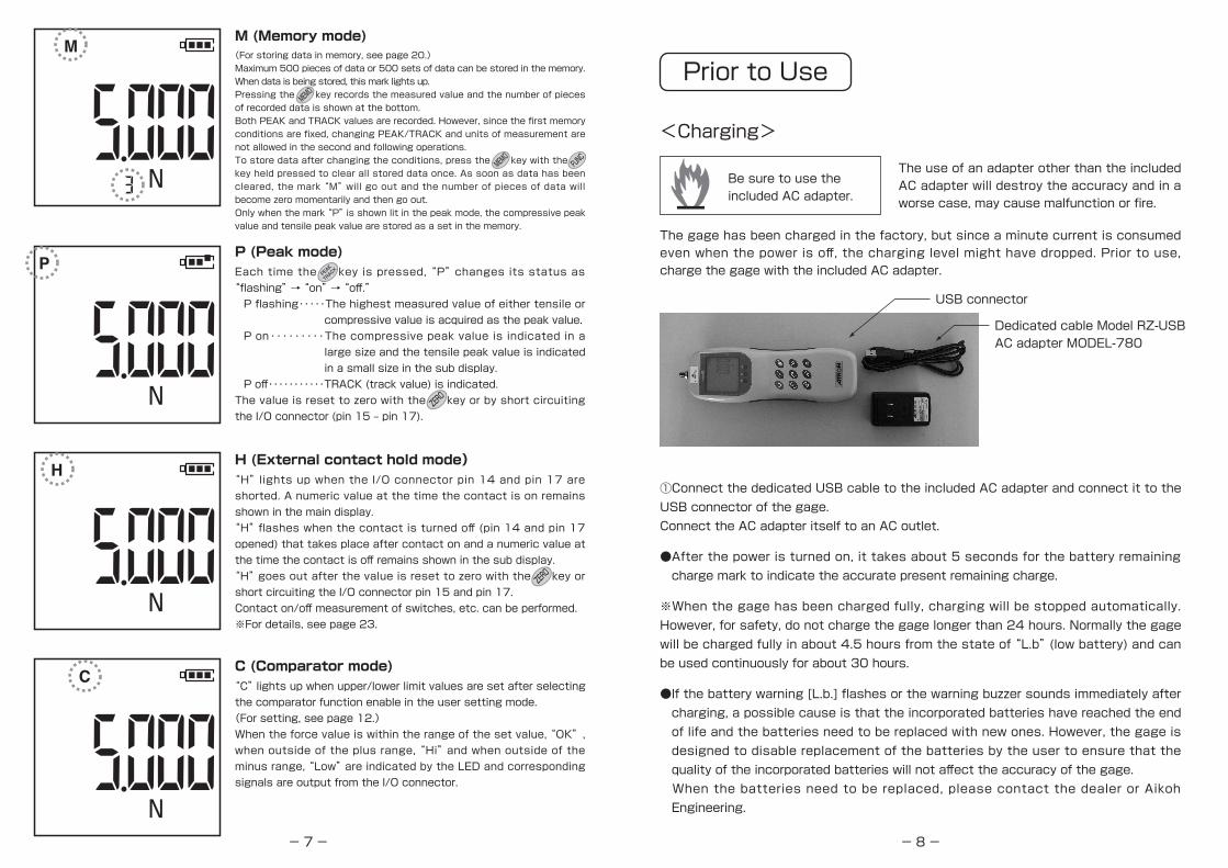
(For storing data in memory, see page 20.)Maximum 500 pieces of data or 500 sets of data can be stored in the memory. When data is being stored, this mark lights up.Pressing the key records the measured value and the number of pieces of recorded data is shown at the bottom.Both PEAK and TRACK values are recorded. However, since the first memory conditions are fixed, changing PEAK/TRACK and units of measurement are not allowed in the second and following operations.To store data after changing the conditions, press the key with the key held pressed to clear all stored data once. As soon as data has been cleared, the mark “M” will go out and the number of pieces of data will become zero momentarily and then go out.Only when the mark “P” is shown lit in the peak mode, the compressive peak value and tensile peak value are stored as a set in the memory.
M (Memory mode)
MEMO
MEMO
FUNC
N
Each time the key is pressed, “P” changes its status as “flashing” → “on” → “off.”P flashing・・・・・The highest measured value of either tensile or
compressive value is acquired as the peak value.P on・・・・・・・・・The compressive peak value is indicated in a
large size and the tensile peak value is indicated in a small size in the sub display.
P off・・・・・・・・・・・TRACK (track value) is indicated.The value is reset to zero with the key or by short circuiting the I/O connector (pin 15 ‒ pin 17).
P (Peak mode)PEAK
TRACK
ZERO
N
“H” lights up when the I/O connector pin 14 and pin 17 are shorted. A numeric value at the time the contact is on remains shown in the main display.“H” flashes when the contact is turned off (pin 14 and pin 17 opened) that takes place after contact on and a numeric value at the time the contact is off remains shown in the sub display.“H” goes out after the value is reset to zero with the key or short circuiting the I/O connector pin 15 and pin 17.Contact on/off measurement of switches, etc. can be performed.※For details, see page 23.
H (External contact hold mode)
ZERO
“C” lights up when upper/lower limit values are set after selecting the comparator function enable in the user setting mode.(For setting, see page 12.)When the force value is within the range of the set value, “OK”, when outside of the plus range, “Hi” and when outside of the minus range, “Low” are indicated by the LED and corresponding signals are output from the I/O connector.
C (Comparator mode)
-8-
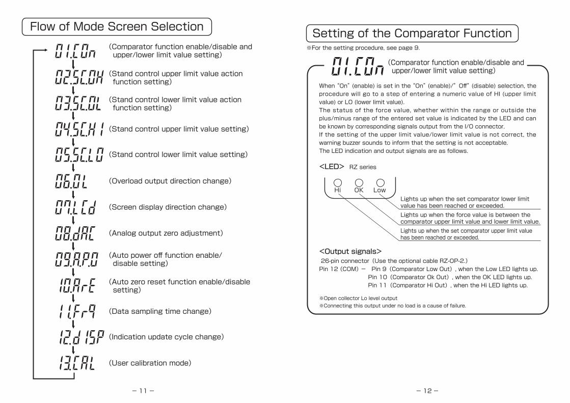
Prior to Use
<Charging>
Be sure to use the included AC adapter.
The use of an adapter other than the included AC adapter will destroy the accuracy and in a worse case, may cause malfunction or fire.
The gage has been charged in the factory, but since a minute current is consumed even when the power is off, the charging level might have dropped. Prior to use, charge the gage with the included AC adapter.
USB connector
Dedicated cable Model RZ-USBAC adapter MODEL-780
①Connect the dedicated USB cable to the included AC adapter and connect it to the USB connector of the gage.Connect the AC adapter itself to an AC outlet.
●After the power is turned on, it takes about 5 seconds for the battery remaining charge mark to indicate the accurate present remaining charge.
※When the gage has been charged fully, charging will be stopped automatically. However, for safety, do not charge the gage longer than 24 hours. Normally the gage will be charged fully in about 4.5 hours from the state of “L.b” (low battery) and can be used continuously for about 30 hours.
●If the battery warning [L.b.] flashes or the warning buzzer sounds immediately after charging, a possible cause is that the incorporated batteries have reached the end of life and the batteries need to be replaced with new ones. However, the gage is designed to disable replacement of the batteries by the user to ensure that the quality of the incorporated batteries will not affect the accuracy of the gage. When the batteries need to be replaced, please contact the dealer or Aikoh Engineering.

-9-
User Setting Mode
<Mode selection and setting>
①
②
Pressing and holding the key for 3 seconds or
longer sets the user setting mode.
At the beginning, the following mode select screen
will appear.
FUNC
Go to 01 to 13 with the key and select it with
the key.
On the setting screen, the name of the selected
mode is shown at the top.
ENT
-10-
③
④
⑤
On the setting screen, change the setting with
the key.
When the setting is such as ON-OFF, select either
one with the key and accept it with the
key and then return to the select screen.
To enter a numeric value, follow the steps below.
ENT
After moving it to a digit to set or change, select
a value to set with the key.
Go to a desired digit with the key and enter a
numeric value with the key. The minus sign is
added with the key.
(When the sign “-” is shown, it is a compression
value and when no sign is shown, it is a tension
value.)
MEMO
To add the minus sign, press the key. Then
the sign “-” will be shown on the left side of the
value. When the key is pressed again, the sign “-”
will go out, indicating that the value is a plus value.
MEMO
Accept the value with the key and return to
the mode select screen with the key.ENT
FUNC
-11-
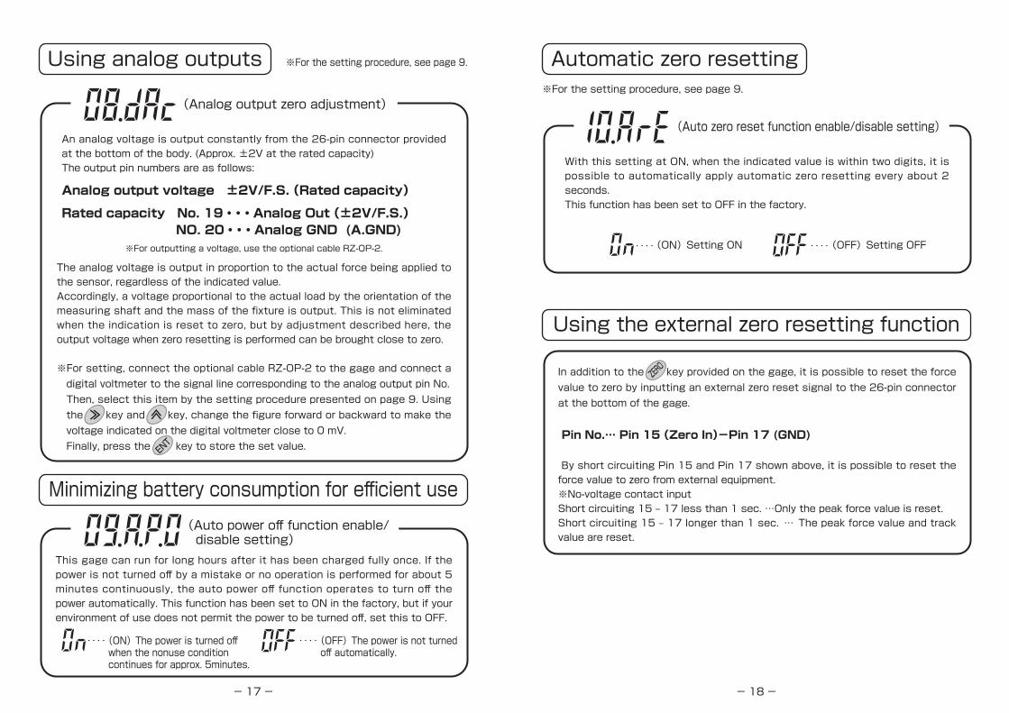
Flow of Mode Screen Selection(Comparator function enable/disable and upper/lower limit value setting)
(Stand control upper limit value action function setting)
(Stand control lower limit value action function setting)
(Stand control upper limit value setting)
(Stand control lower limit value setting)
(Overload output direction change)
(Screen display direction change)
(Analog output zero adjustment)
(Auto power off function enable/ disable setting)
(Auto zero reset function enable/disable setting)
(Data sampling time change)
(Indication update cycle change)
(User calibration mode)
-12-
Setting of the Comparator Function
<LED>
<Output signals>
RZ series
Lights up when the set comparator lower limit value has been reached or exceeded.Lights up when the force value is between the comparator upper limit value and lower limit value.Lights up when the set comparator upper limit value has been reached or exceeded.
(Comparator function enable/disable and upper/lower limit value setting)
※For the setting procedure, see page 9.
When “On” (enable) is set in the “On” (enable)/”Off” (disable) selection, the procedure will go to a step of entering a numeric value of HI (upper limit value) or LO (lower limit value).The status of the force value, whether within the range or outside the plus/minus range of the entered set value is indicated by the LED and can be known by corresponding signals output from the I/O connector.If the setting of the upper limit value/lower limit value is not correct, the warning buzzer sounds to inform that the setting is not acceptable.The LED indication and output signals are as follows.
26-pin connector(Use the optional cable RZ-OP-2.)Pin 12 (COM) - Pin 9(Comparator Low Out), when the Low LED lights up. Pin 10(Comparator Ok Out), when the OK LED lights up. Pin 11(Comparator Hi Out), when the Hi LED lights up.
※Open collector Lo level output※Connecting this output under no load is a cause of failure.
Hi OK Low

-13-
Brief Explanation
Concept of the upper limit value and lower limit value
※Both of the comparator function and stand control function operate based on this concept.
1. When the set values of both the upper limit value and lower limit value are on the plus (tension) side (A, B) in the figure, “A” which is larger is the upper limit value and “B” is the lower limit value.
2. When the set values of both the upper limit value and lower limit value are on the minus (compression) side (D, C) in the figure, “D” which is larger in absolute value is the upper limit value and “C” is the lower limit value.
3. When the set values of the upper limit value and lower limit value are on the plus side and minus side of zero (B, C), “B” which is on the plus side is the upper limit value and “C” which is on the minus side is the lower limit value regardless of their values.
0
A
B
C
D
+
-
-14-
Setting of the stand control function
<Output signals>
(Stand control lower limit value action function setting)
※For the setting procedure, see page 9.
This setting is useful when Aikoh’s electric test stand compatible with this gage is used in combination. By setting a desired force value, the test stand can be moved up/down or stopped when the actual force has reached the force set value to protect the user’s test sample and at the same time, various tests can be controlled in force. There are four types of setting as shown below, from which you can select one.
26-pin connector(Use the optional cable RZ-OP-2.)Pin 3 (COM)- Pin 5(Stand Control STOP) Pin 6(Stand Control UP) Pin 7(Stand Control DOWN)
※Open collector pulse output, withstand voltage 30 V max, on voltage 0.5 V max. (at suction current of 5 mA)
UP (Up action)
Stop (Stop)
no (Disabled)
down (Down action)
When the actual force reaches each value set in and , a signal corresponding to the setting will be output from the 26-pin I/O connector provided at the bottom of the gage to activate the action selected here.
(Stand control upper limit value action function setting)
(Stand control lower limit value setting)
(Stand control upper limit value setting)
Here set a force value for and to function. functions at the set value of and functions at the set value of For the concept of the upper limit value and lower limit value, read the brief explanation presented on page 13 and understand them prior to making setting here.

-15-
Precautions for installation on the electric test stand※For the setting procedure, see page 9.
※To use the gage in combination with other electric test stand, confirm the stop direction prior to making this setting. If the setting is incorrect, even if an overload occurs, the electric test stand will not stop, breaking the force sensor.
※For connection, use the optional cable RZ-OP-1 or RZ-OP-2.
MODEL-1308UCapacity / 1000NThe gage mount ing part is moved up and down electrically. The power supply is a multi power supply of 100 V to 240 V.
※The digital force gage is not included with either model.
MODEL-2257Capacity / 500NThis model is electrical and when the included base plate is exchanged, it can be used either as the vertical type or the horizontal type.The power supply is a mult i power supply of 100 V to 240 V.
(Overload output direction change)
If a force exceeding the rated capacity is applied to the measuring shaft, the force sensor may be broken and the gage may fail.When the gage is installed on Aikoh’s electric test stand, an overload signal can be output from the 26-pin I/O connector to the electric test stand to stop the stand. For this purpose, it is necessary to make setting according to the action direction of the electric test stand and the direction of a force to be applied. allows selection of either or For a combination of Aikoh’s electric test stand Model 1308 and Model 2257, select
Vertical/horizontal combined type
- 16-
Changing the screen display direction
(Screen display direction change)
※For the setting procedure, see page 9.
The display of the measured value and unit can be reversed. Use this function when mounting the gage on a test stand.The contents of setting and the display direction are as follows.
Direction of the display when the measuring shaft faces upward.
Direction of the display when the measuring shaft faces downward.
(UP)Upward selected (DOWN)Downward selected
NN
-17-
Using analog outputs
Minimizing battery consumption for efficient use
(Analog output zero adjustment)
※For the setting procedure, see page 9.
An analog voltage is output constantly from the 26-pin connector provided at the bottom of the body. (Approx. ±2V at the rated capacity)The output pin numbers are as follows:
This gage can run for long hours after it has been charged fully once. If the power is not turned off by a mistake or no operation is performed for about 5 minutes continuously, the auto power off function operates to turn off the power automatically. This function has been set to ON in the factory, but if your environment of use does not permit the power to be turned off, set this to OFF.
Analog output voltage ±2V/F.S. (Rated capacity)
Rated capacity No. 19・・・Analog Out (±2V/F.S.) NO. 20・・・Analog GND (A.GND)
※For outputting a voltage, use the optional cable RZ-OP-2.
(Auto power off function enable/ disable setting)
The analog voltage is output in proportion to the actual force being applied to the sensor, regardless of the indicated value.Accordingly, a voltage proportional to the actual load by the orientation of the measuring shaft and the mass of the fixture is output. This is not eliminated when the indication is reset to zero, but by adjustment described here, the output voltage when zero resetting is performed can be brought close to zero.
※For setting, connect the optional cable RZ-OP-2 to the gage and connect a digital voltmeter to the signal line corresponding to the analog output pin No. Then, select this item by the setting procedure presented on page 9. Using the key and key, change the figure forward or backward to make the voltage indicated on the digital voltmeter close to 0 mV.Finally, press the key to store the set value.EN
T
(ON)The power is turned off when the nonuse condition continues for approx. 5minutes.
(OFF)The power is not turned off automatically.
- 18-
Automatic zero resetting
Using the external zero resetting function
(Auto zero reset function enable/disable setting)
※For the setting procedure, see page 9.
With this setting at ON, when the indicated value is within two digits, it is possible to automatically apply automatic zero resetting every about 2 seconds.This function has been set to OFF in the factory.
(ON)Setting ON (OFF)Setting OFF
In addition to the key provided on the gage, it is possible to reset the force value to zero by inputting an external zero reset signal to the 26-pin connector at the bottom of the gage.
Pin No.… Pin 15 (Zero In)-Pin 17 (GND)
By short circuiting Pin 15 and Pin 17 shown above, it is possible to reset the force value to zero from external equipment.※No-voltage contact inputShort circuiting 15 ‒ 17 less than 1 sec. …Only the peak force value is reset.Short circuiting 15 ‒ 17 longer than 1 sec. … The peak force value and track value are reset.
ZERO

-19-
Setting measurement conditions
Changing over between 3 units
(Data sampling time change)
Select one from 1, 2, 5, 10 and 20 times/sec.(Factory setting 5 times/sec)In either of the TRACK and PEAK modes, data is indicated according to the set indication update cycle.
Change the internal sampling time of measured values.Select one from 1 ms, 5 ms, 16 ms, 50 ms, 125 ms and 250 ms. (Factory setting 50 ms)
TRACK mode … Data is sampled continuously for the set sampling time and indicated according to the set indication update cycle.PEAK mode … Data is judged for peak values continuously for the set sampling time and indicated according to the set indication update cycle.
To change the data sampling time, change (Indication update cycle change)at the same time.
※For communications with a PC, since 1.3 ms is required for transfer of one piece of data, when 1 ms is selected, data is sent every 2 ms.
(Indication update cycle change)
When the power is turned on while pressing the key, “Unit” is shown. Then
press the key to show “Unit n”(Newton).
Press the key to change “Unit n” to “Unit 3”(3 units) and accept it with the
key.
After changing, each time the key is pressed, the unit will be changed in the
order of Kgf (kilogram), N (Newton) and lb (pound).
In the factory, the unit has been set to the statutory measurement unit N
(Newton) stipulated in the Measurement Act.
ENT
ENT
Unit change mode(Initial setting: N (Newton), changeable to one of 3 units)
-20-
Measurement ①<Measurement by use of the memory function>
■Collection of data by field measurement
①
① Press ② while pressing ①.
②
②
N
The memory function of this gage can store maximum 500 sets of measured force values with the compressive force as “-” and the tensile force as “+.” The stored data can be output to a printer and PC.
※When data is collected with the memory function or when collected data has been sto red in the memory, “PEAK/TRACK” and units cannot be changed. To change the conditions, clear all memory data.
All clear of the memoryTo clear data in the memory, press the key
while pressing the key. Then the memory
will be cleared completely.FUNC
MEMO
Display modeSelect either the PEAK value or TRACK value
according to the nature of measurement.
Each time the key is pressed, “P” changes its
status in the order of “flashing” → “on”→ “off.”
P flashing……The highest measured value of
either tensile or compressive
value is acquired as the peak
value.
P on……………The compressive peak value is
indicated in a large size and the
tensile peak value is indicated in
a small size in the sub display.
P off……………TRACK(track value)is indicated.
PEAK
TRACK

-21-
③
M
N
Checking the unitsSelect a unit of measurement from N, Kgf and lb.
(3-unit system)
Each time the key is pressed, the unit is shown
below the force value in the order of Kgf, lb and N.
※This function cannot be used when “N” has been
set.
④
⑤
Force zeroPressing the key without applying a force resets
the indicated value to zero.
Continue measurement.
ZERO
Each time the key is pressed, the number of
pieces of data in the memory is shown in the force
display for about 1 second, “M” lights up in the
upper left corner of the screen and the present
number of pieces of data in the memory is shown in
the lower right. When data is stored in the memory,
the indicated value will be reset to zero and the
gage will become ready for the next measurement.
MEMO
Storing and printing dataIf there is data that needs to be stored during
measurement, press the key. Then that data will
be stored in the memory.
When the key is pressed, the data will be
printed.
MEMO
PRT
-22-
①
①Press ② while pressing ①.
②
②
Calling and deleting dataOnly the data that was stored last in the memory
can be called and deleted.
When the key is pressed while pressing the
key, the data stored last wil l be called. Then
pressing the key deletes the called data and the
gage will return to the normal operation. If the
key is pressed without pressing the key, the
called data will be returned to the memory.
FUNC
ZERO
ZERO
MEMO
Printing data in the memoryThe printers that are connectable to this gage are
the following two types:
①MITUTOYO-made DP-1VR (Mitutoyo Digimatic
output connection)
※For connection, use the optional cable RZ-OP-3.
②SANEI ELECTRIC-made BL2-58SNWJC (RS232C
connection)
※For connection, use the optional cable RZ-OP-4.
When the gage has been connected to a printer,
print data in the memory collectively.
When the key is pressed while pressing the
key, the data in the memory will be printed one after
another.
FUNC
PRT
-23-
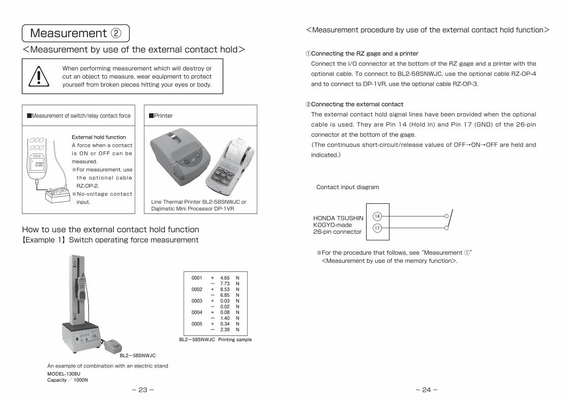
When performing measurement which will destroy or cut an object to measure, wear equipment to protect yourself from broken pieces hitting your eyes or body.
■Measurement of switch/relay contact force ■Printer
External hold functionA force when a contact is ON or OFF can be measured.※For measurement, use the opt iona l cab le RZ-OP-2.
※No-voltage contact input. Line Thermal Printer BL2-58SNWJC or
Digimatic Mini Processor DP-1VR
How to use the external contact hold function【Example 1】Switch operating force measurement
An example of combination with an electric standMODEL-1308UCapacity / 1000N
BL2-58SNWJC
BL2-58SNWJC Printing sample
0001 + 4.65 N - 7.73 N0002 + 8.53 N - 6.85 N0003 + 0.03 N - 0.02 N0004 + 0.08 N - 1.40 N0005 + 0.34 N - 2.39 N
Measurement ②<Measurement by use of the external contact hold>
-24-
①Connecting the RZ gage and a printer
Connect the I/O connector at the bottom of the RZ gage and a printer with the
optional cable. To connect to BL2-58SNWJC, use the optional cable RZ-OP-4
and to connect to DP-1VR, use the optional cable RZ-OP-3.
②Connecting the external contact
The external contact hold signal lines have been provided when the optional
cable is used. They are Pin 14 (Hold In) and Pin 17 (GND) of the 26-pin
connector at the bottom of the gage.
(The continuous short-circuit/release values of OFF→ON→OFF are held and
indicated.)
<Measurement procedure by use of the external contact hold function>
Contact input diagram
※For the procedure that follows, see “Measurement ①” <Measurement by use of the memory function>.
HONDA TSUSHIN KOGYO-made 26-pin connector
-25-
H
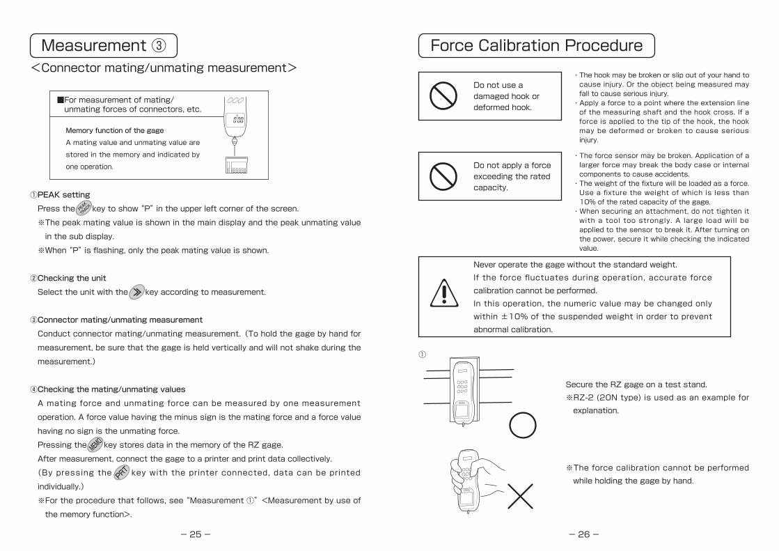
①PEAK setting
Press the key to show “P” in the upper left corner of the screen.
※The peak mating value is shown in the main display and the peak unmating value
in the sub display.
※When “P” is flashing, only the peak mating value is shown.
②Checking the unit
Select the unit with the key according to measurement.
③Connector mating/unmating measurement
Conduct connector mating/unmating measurement.(To hold the gage by hand for
measurement, be sure that the gage is held vertically and will not shake during the
measurement.)
④Checking the mating/unmating values
A mating force and unmating force can be measured by one measurement
operation. A force value having the minus sign is the mating force and a force value
having no sign is the unmating force.
Pressing the key stores data in the memory of the RZ gage.
After measurement, connect the gage to a printer and print data collectively.
(By pressing the key with the printer connected, data can be printed
individually.)
※For the procedure that follows, see “Measurement ①”<Measurement by use of
the memory function>.
■For measurement of mating/ unmating forces of connectors, etc.
Memory function of the gage
A mating value and unmating value are
stored in the memory and indicated by
one operation.
PEAK
TRACK
MEMO
PRT
Measurement ③<Connector mating/unmating measurement>
-26-
Force Calibration Procedure
Do not use a damaged hook or deformed hook.
・The hook may be broken or slip out of your hand to cause injury. Or the object being measured may fall to cause serious injury.・Apply a force to a point where the extension line of the measuring shaft and the hook cross. If a force is applied to the tip of the hook, the hook may be deformed or broken to cause serious injury.
・The force sensor may be broken. Application of a larger force may break the body case or internal components to cause accidents.・The weight of the fixture will be loaded as a force. Use a fixture the weight of which is less than 10% of the rated capacity of the gage.・When securing an attachment, do not tighten it with a tool too strongly. A large load will be applied to the sensor to break it. After turning on the power, secure it while checking the indicated value.
Do not apply a force exceeding the rated capacity.
Never operate the gage without the standard weight.If the force fluctuates during operation, accurate force calibration cannot be performed.In this operation, the numeric value may be changed only within ±10% of the suspended weight in order to prevent abnormal calibration.
Secure the RZ gage on a test stand.※RZ-2 (20N type) is used as an example for explanation.
※The force calibration cannot be performed while holding the gage by hand.
①

-27-
N
②
③
④
Pressing the key turns on the power and the rated capacity will be shown(for approx. 3 seconds).
Turn the hook in the arrow direction to mount it on the measuring shaft.※Be sure to screw in the hook fully. If a fixture (such as a basket) is needed for calibration, hang it on the hook.Note that if the weight of the hook and fixture (such as a basket) is more than ±10% of the rated capacity of the RZ gage, an error will occur and setting will be disabled and the gage will return to the measurement standby state.
Press and hold the key for 3 seconds or
longer to go to the user setting mode.
Using the key, go to and accept it
with pressing the key twice.
Press the key to reset the indicated value to
zero.
※If a package exceeding 20% of the rated capacity is loaded or if the force sensor has been damaged and the zero reset range has been exceeded, the indicated value cannot be reset to zero.
ZERO
ENT
FUNC
-28-
⑤
Fixture (such as a basket) in ③
⑥
⑦
Gently hang the calibration standard weight. The weight must be within a range from 1/3 to 1 of the rated capacity.Here, since RZ-2 (20N type) is used as an example, hang a weight of 1/2 (10 N).
When a value has been entered, after making sure that the
weight is not swaying and press the key.
“End” will be shown and press the key several times to reset
to zero, then the calibration finish.
At this time, the weight of the standard weight hung in ⑤ is
stored as the weight of the set value.
※For example, if the value is set as “10.00” for a 9-N weight,
“9 N” will be stored as “10 N”. Be sure to enter the value
that is equal to the weight of the standard weight.
※If the entered set value deviates from the present force value
indicated in the sub display more than ±10%.F.S, the warning
buzzer will sound and calibration will not be accepted.
※This force calibration is a simplified calibration procedure. In order to maintain the accuracy of the RZ gage and ensure reliable measurement, it is recommended that the gage be calibrated periodically by an authorized body. For required costs and days, please contact the dealer from whom you purchased the gage.※The contents of setting and memory data may be changed to the factory setting and data by this calibration and therefore, it is requested that prior to sending the gage for repair or calibration, you keep a record of the data.
1ON
N
The sub display shows the present force value. Move the
flashing digit of the value in the main display with the key.
After moving it to a desired digit, enter the same value as the
mass of the calibration standard weight with the key.
Each t ime the key is pressed, the value increases in
increments of 1 such as 1, 2, 3, … 9, 0, 1, 2.
This is a step to set a value that is equal to the calibration
standard weight in ⑤.
N
ENT
FUNC

-29-
1 13
14 26
I/O connector, 0.8-mm pitch, 26 pins
Input/Output[USB output]The gage may be connected to a PC with the included USB cable to send and manage data.For data management, optional software capable of creating graphs is available. Please contact us.For installation of software, please see the instruction manual of the optional software.
・Signal specifications●Analog output :±2V/FS, 12-bit D/A converter, data update rate 1000 times/second max. The data update rate varies depending on the setting of the data sampling time.●Control output signal:Open collector output, withstand voltage 30 V, suction current 10 mA
max, on-voltage 0.5 V max. ●Control input signal :5 V, C-MOS level, 10 kΩ pull-up resistor provided
pinNo
1
2
3
4
5
6
7
8
9
10
11
12
13
14
15
16
17
18
19
20
21
22
23
24
25
26
Signal Name
Over Load Up
Over Load Down
Over Load Common
- - - - - - - - - - - - - - - - - -
Stand Control Stop
Stand Control Up
Stand Control Down
- - - - - - - - - - - - - - - - - -
Comparator Low Out
Comparator Ok Out
Comparator Hi Out
Comparator Common
- - - - - - - - - - - - - - - - - -
Hold In
Zero In
Print In
GND
- - - - - - - - - - - - - - - - - -
Analog Out
Analog GND
- - - - - - - - - - - - - - - - - -
- - - - - - - - - - - - - - - - - -
- - - - - - - - - - - - - - - - - -
- - - - - - - - - - - - - - - - - -
- - - - - - - - - - - - - - - - - -
- - - - - - - - - - - - - - - - - -
Description
Overload limiter output signal
(Overload output)
Not used
Test stand control output signal
Not used
Comparator judgment output signal
Not used
External hold signal input
External zero reset signal input
External print signal input
Ground
Not used
Analog output
Not used
Not used
Not used
Not used
Not used
Not used
Connector pin assignment[Input/output connector]
- 30-
・Optional Cable I/O cable [RZ-OP-1]
2000mm
150mm
※Pin No. mark here
・Honda Tsushin Kogyo 26-pin male connector
HDR-E26MSG1+
・Honda Tsushin Kogyo Case for large dia cable
HDR-E26LPK+
Signal cable (Black) UL, AWM2464 ・OD 7.0 - 8.0 mm ・Core wire 16 pcs ・Core wire OD 1.1 - 1.5 ・AWG24 ( 0.2㎟ )
pinNo1234567891011121314151617181920212223242526
Signal NameOver Load UpOver Load DownOver Load Common----------Stand Control StopStand Control UpStand Control Down---------- Comparator Low OutComparator Ok OutComparator Hi OutComparator Common----------Hold InZero InPrint InGND----------Analog OutAnalog GND------------------------------------------------------------
Termination10-mm soldering10-mm soldering10-mm soldering--------10-mm soldering10-mm soldering10-mm soldering--------No terminationNo terminationNo terminationNo termination--------No terminationNo terminationNo terminationNo termination--------No terminationNo termination------------------------------------------------
[RZ-OP-1]YesYes--------YesYesYes----NoNoNoNo
----NoNoNoNo
----NoNo
------------------------
Wire ColorYellowWhitePink
GreenOrangePurple--WhiteWhiteWhiteWhite--GrayBlueBrownSky-blue--RedBlack------------
----------------BlueGreenRedBlack----------------------------
-31-
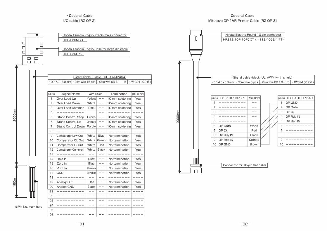
・Optional CableI/O cable [RZ-OP-2]
pinNo1234567891011121314151617181920212223242526
Termination10-mm soldering10-mm soldering10-mm soldering--------10-mm soldering10-mm soldering10-mm soldering--------No terminationNo terminationNo terminationNo termination--------No terminationNo terminationNo terminationNo termination--------No terminationNo termination------------------------------------------------
[RZ-OP-2]YesYesYes----YesYesYes----YesYesYesYes----YesYesYesYes----YesYes------------------------
Wire ColorSignal NameOver Load UpOver Load DownOver Load Common----------Stand Control StopStand Control UpStand Control Down---------- Comparator Low OutComparator Ok OutComparator Hi OutComparator Common----------Hold InZero InPrint InGND----------Analog OutAnalog GND------------------------------------------------------------
※Pin No. mark here
150mm
2000mm
・Honda Tsushin Kogyo Case for large dia cable
HDR-E26LPK+
・Honda Tsushin Kogyo 26-pin male connector
HDR-E26MSG1+
Signal cable (Black) UL, AWM2464 ・OD 7.0 - 8.0 mm ・Core wire 16 pcs ・Core wire OD 1.1 - 1.5 ・AWG24 ( 0.2㎟ )
YellowWhitePink
GreenOrangePurple--WhiteWhiteWhiteWhite--GrayBlueBrownSky-blue--RedBlack------------
----------------BlueGreenRedBlack----------------------------
-32-
Optional CableMitutoyo DP-1VR Printer Cable [RZ-OP-3]
Signal cable (black) UL, AWM (with shield)・OD 4.5 - 5.0 mm ・Core wire 5 pcs ・Core wire OD 1.0 - 1.5 ・AWG24 ( 0.2㎟ )
2000mm
Hirose Electric Round 10-pin connector
HR212-10P-10PC(71), (112-4052-4-71)
Connector for 10-pin flat cable
pinNo12345678910
HR212-10P-10PC(71)--------------------------------------------------DP DataDP CkDP Rdy INDP Req INDP GND
Wire Color----------WhiteRedBlackOrangeBrown
pinNo12345678910
HIF3BA-10D2.54RDP GNDDP DataDP CkDP Rdy INDP Req IN--------------------------------------------------

-33-
Optional CableSanei Electric Line Thermal Printer Cable [RZ-OP-4]
Signal cable (black) UL, AWM (with shield)・OD 4.5 - 5.0 mm ・Core wire 5 pcs ・Core wire OD 1.0 - 1.5 ・AWG24 ( 0.2㎟ )
Hirose Electric Round 10-pin connector
HR212-10P-10PC(71), (112-4052-4-71)
9-pin D-sub connector (female)
pinNo12345678910
HR212-10P-10PC(71)RDRTSTDCTSD.GND--------------------------------------------------
Wire ColorWhiteRedBlackOrangeBrown----------
pinNo123456789
D-sub9P(Female)----------RDTD----------D.GND----------RTSCTS----------
2000mm
-34-
RZ-20
200N(20Kgf)
0.1-200.0N(10gf-20.00Kgf)
RZ-2
20N(2Kgf)
0.01-20.00N(1gf-2.000Kgf)
RZ-5
50N(5Kgf)
0.01-50.00N(1gf-5.000Kgf)
RZ-50
500N(50Kgf)
0.1-500.0N(10gf-50.00Kgf)
RZ-100
1000N(100Kgf)
0.1-1000.0N(10gf-100.00Kgf)
RZ-10
100N(10Kgf)
0.01-100.00N(1gf-10.000Kgf)
List of Models
Standard specifications
RZ-1
10N(1Kgf)
0.001-10.000N(0.1gf-1.0000Kgf)
0.001N (0.1gf) 0.01N (1gf) 0.1N (10gf)
・Unit of measurement ………… N or (gf) Kgf/N/lb selection・Accuracy ………………………… Within ±0.2% of the rated capacity・Allowable overload …………… 120% of the rated capacity (Overload warning at about 110%)・Measurement system ………… Track mode / Peak hold mode / Compression/tension peak hold
mode selection・Indication update cycle ……… 1 time/sec, 2 times/sec, 5 times/sec, 10 times/sec,
20 times/sec selection・Sampling cycle ………………… 1 ms, 5 ms, 16 ms, 50 ms, 125 ms and 250 ms selection・Working temperature range … 0 to +40℃・Guaranteed temperature range … +5 to +40℃・Continuous working hours …… 30 hours after full charge・Power supply …………………… Dedicated nickel-metal hydride AAA battery x 3, dedicated AC
adapter: Model 780 (5 VDC/1000 mA)B Dedicated USB cable: Model RZ-USB・External dimensions …………… W68 x D40 x H232 mm・Mass ……………………………… Approx. 375 g
Rated capacity(R.C.)
Indication range
Model
Min. indicationresolution
Outside dimensions

-35-
Warranty
MODEL
SERIAL No.
Warranty period: One (1) year up to
This warranty guarantees that the gage will be repaired free of charge only in the following cases:1. The gage malfunctioned due to an initial defect.2. The gage failed despite it was used in the correct way.Please contact a nearest Aikoh Engineering sales office or the dealer from whom you purchased the gage.
3. In the case of the following failures and damages, you are liable for the costs of repair even within the warranty period:(1) A fa i lure or damage due to improper handl ing or use or
unauthorized modification or repair.(2) A failure or damage that may occur during installation or
transportation to an installation place.(3) A failure or damage due to fire, smoke, gas, earthquake, lightning
and other natural disaster or external causes such as an abnormal voltage.
(4) A failure or damage due to causes attributable to equipment connected to the gage.
4. When you want the gage to be repaired or serviced, please disconnect other equipment from the gage prior to sending it.
Dealer