INSTRUCTION MANUAL - supsew.com DCN Instruction Manual.pdf · ieans, working...
18
INSTRUCTION MANUAL SEIKO SEWING MACHINE CO.,LTD. From the library of: Superior Sewing Machine & Supply LLC
Transcript of INSTRUCTION MANUAL - supsew.com DCN Instruction Manual.pdf · ieans, working...
INSTRUCTION MANUAL
SEIKO SEWING MACHINE CO.,LTD.
From the library of: Superior Sewing Machine & Supply LLC
@
1. M 1
2. m— —2
3. - - ^ —^- 24. Jnift 3
5. 3
6. 4
7. nmmmm 5
8. 6
9. -: ——— — 7
—————-.—.-cg'11. —9
12. -,- — 9
13. —---~— -,——10
14. ^—12
15. 13
16. u
17. 15
18. 15•'•1 ^ T-
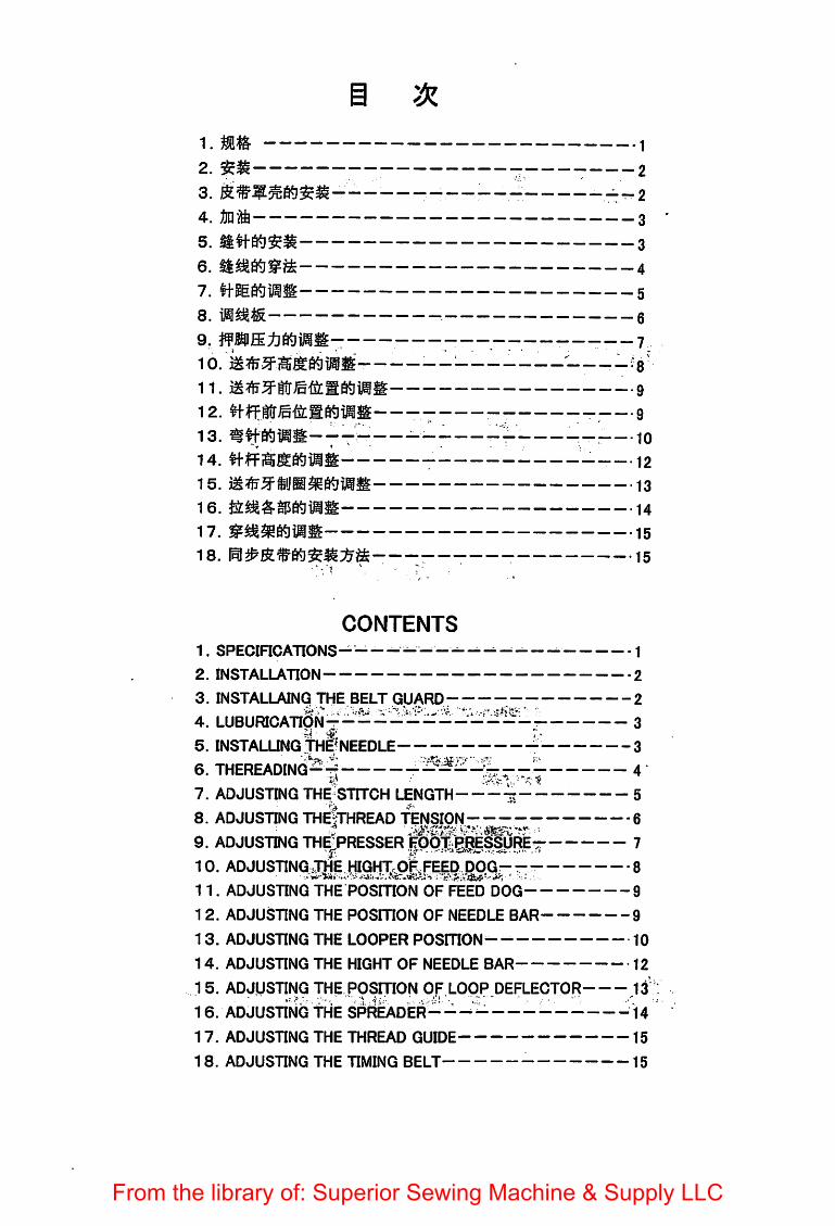
CONTENTS1. SPECinCATIONS- - - 1
2. INSTALLATION 2
3. INSTALLAING THE BELT GUARD; 2.a'..'•••iii- "x*'/."' "•
4. LUBURICATIpN- 3
5. INSTALUNGTHgNEEDLE 3
6. THEREADING-^ 47. ADJUSTING THE STITCH LENGTH — 5
8. ADJUSTING THE|tHREAD TENSION 69. ADJUSTING THfPRESSERrobTlRES^RE- 710. ADJUSTING OTE HIGHTrOF,FEED pOGr- - 8
11. ADJUSTING THE POSITION OF FEED DOG 9
12. ADJUSTING THE POSITION OF NEEDLE BAR 9
13. ADJUSTING THE LOOPER POSITION-- 10
14. ADJUSTING THE HIGHT OF NEEDLE BAR 12
15. ADJUSTING THE POSITION OF LOpP.DEFLECTOR 13
16. ADJUSTING fMe spreader---- — H17. ADJUSTING THE THREAD GUIDE 15
18. ADJUSTING THE TIMING BELT 15
From the library of: Superior Sewing Machine & Supply LLC
1.
^ # DCN^?y?^o°p
4,000 s.p.m.
M:k^m 6.4inin
31.75mm
nmm^ 8mm
DVX57 #11~#25 lfN^t#22
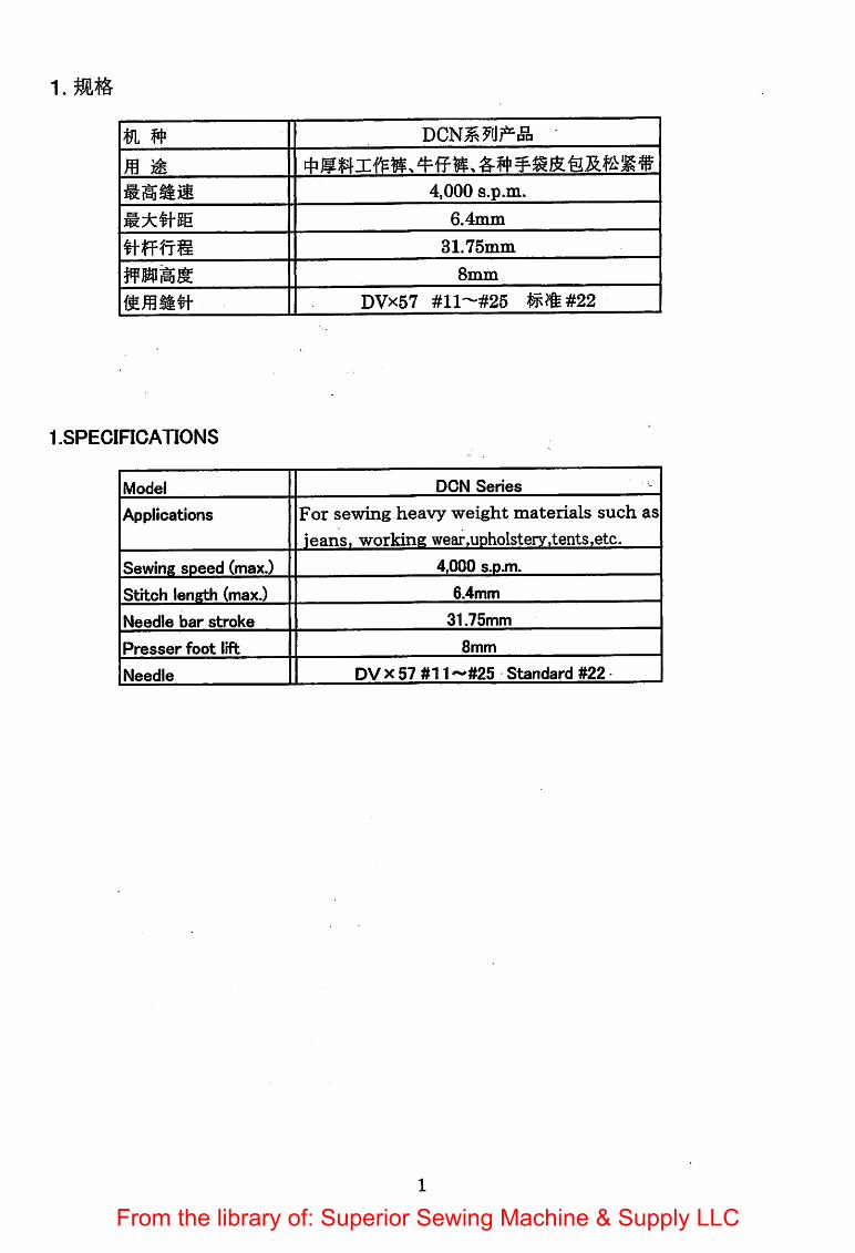
1.SPECIRCAT10NS
Model DON Series
Applications For sewing heavy weight materials such as
ieans, working wear.UDholstery.tents.etc.
Sewing speed (max.) 4.000 s.o.m.
Stitch length (max.) 6.4mm
Needle bar stroke 31.75mm
Presser foot lift 8mm
Needle DV X 57 #11 -'#25 Standard #22
From the library of: Superior Sewing Machine & Supply LLC
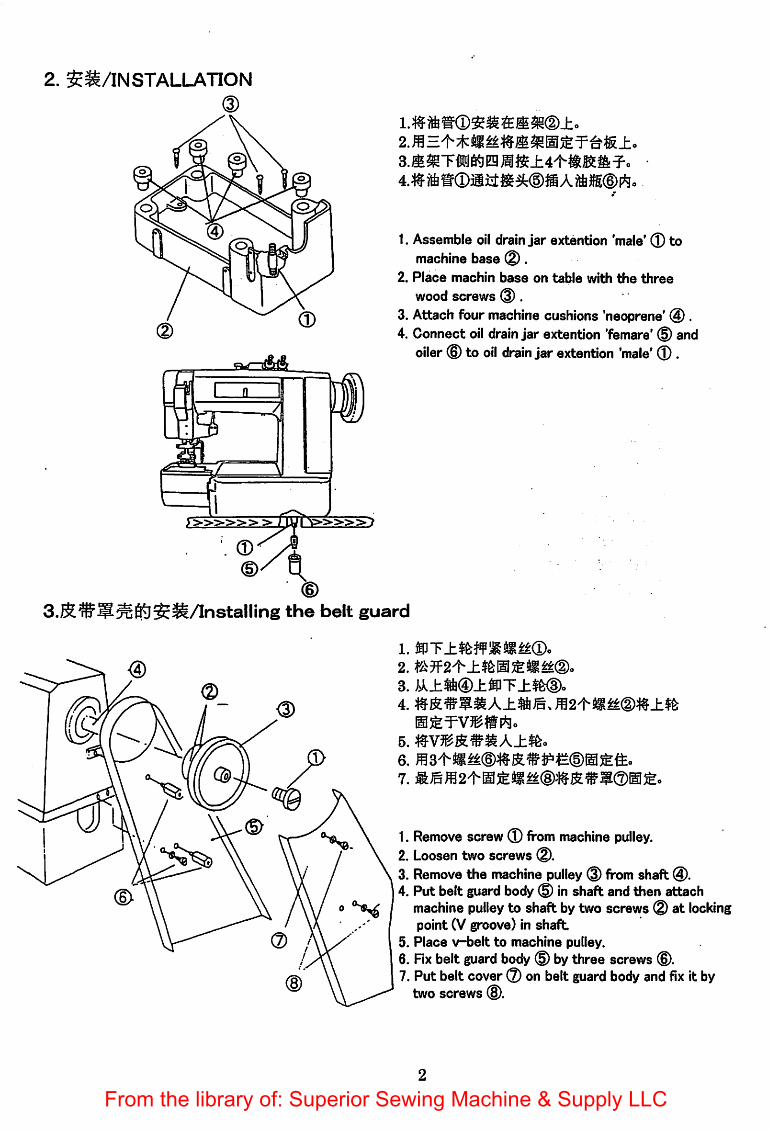
2. SS/INSTALLATION
^
3.Jll^TiiJ6^Eg^i$±4't-ili^il:^-
1. Assemble oil drainjar extention 'male' ® tomachine base ®.
2. Place machin base on table with the three
wood screws @.3. Attach four machine cushions 'neoprene' @ .4. Connect oil drainjar extention 'femare' ® and
oiler © to oil drain jar extention 'male' ® .
3.R®5^65j$^/lnstalling the belt guard
1. mT±^wMm^®o2.
3. i^^±2i®±®T±$fe®o4.
5.
7. WLmm2^m&m^®m^^w®m^.
1. Remove screw ® from machine pulley.2. Loosen two screws ®.3. Remove the machine pulley ® from shaft ®.4. Put belt guard body ® in shaft and then attach
machine pulley to shaft by two screws ® at lockingpoint (V groove) in shaft
5. Place v-belt to machine pulley.6. Rx belt guard body ® bythree screws ©.7. Put belt cover ® on belt guard body and fix it by
two screws ®.
From the library of: Superior Sewing Machine & Supply LLC
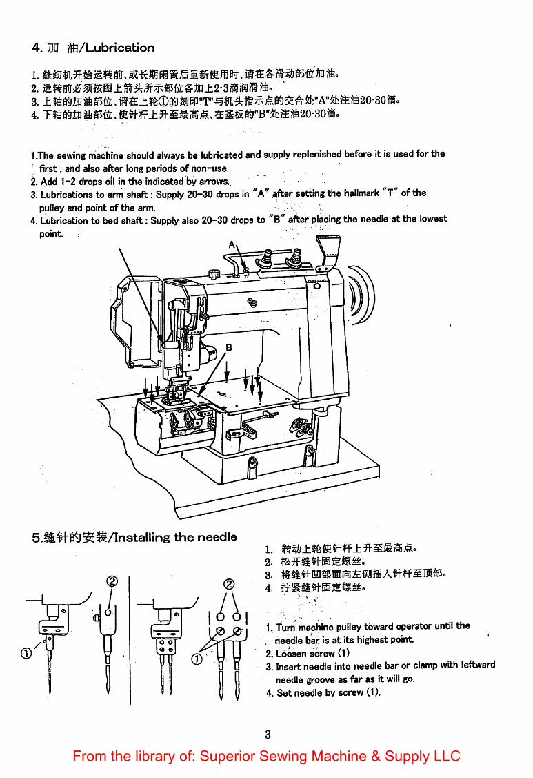
4. Dn ?ft/Lubrication
1.
4. T%S«lJO jftasffc.fi!tfff4*ffiKl"B"&ffiift20-i
1.The sewing machine shouldalways be lubricated and supply replenished before it is used for the' first, and also after long periods of non-use.
2. Add 1-2 drops oil in the indicated by arrows..3. Lubrications to arm shaft: Supply 20-30 drops in "A'' aftersetting the hallmark "T"of the
pulley and point of the arm.4. Lubrication to bed shaft: Supply also 20—30 drops to "B after placing the needle at the lowest
pointAi
S-lfe^fteS^/Installing the needle1.
2.
3-
1. Turn machine pulley toward operator until the, needle bar is at its highest point2. Loosen screw (1)
3. Insert needle into needle bar or clamp with leftwardneedle groove as far as it will go.
4. Set needle by screw (1).
From the library of: Superior Sewing Machine & Supply LLC
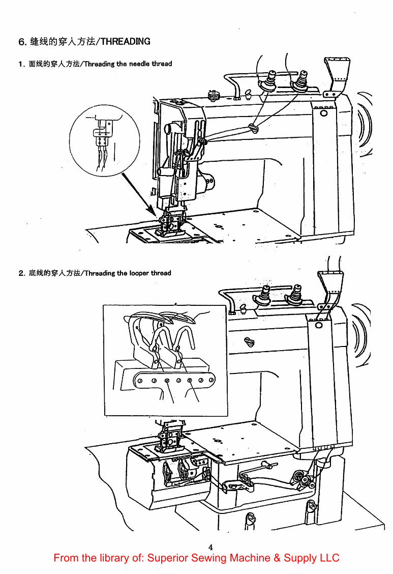
6. ^^Kl^AlJ^ft/THREADING
1. ®^6^^A;^^Ahreading the needle thread
2. jlS^6^^A^^/Threading the looper thread
a Q & o (S> Q> Q>
4
=U
M
From the library of: Superior Sewing Machine & Supply LLC

7.ftE66i]ilSS/Adjusting the stitch length
Ji$fe^iB/Pulley mark A 8 C D E F
H'£&(mm)/Sutich length 6.4 4.9 3.4 2 1.2 1
1. Depress feed regulating plunger ®. Continue to hold plunger down and turn machine pulley © towardoperator until plunger enters notch In arm shaft eccentric. Then turn plungers 90 degrees to direction A.(locking position)
2. Depress button © located In the center of machine bed until button enters notch In bed shaft eccentric.3. Hold down, and turii machine pulley © toward direction B to Increase length of stitch, or toward
direction 0 to decrease length of stitch.
4. When desired length Is obtained, release the button and turn plunger ® toward direction A until it springsoutward.
Caution : Never operate machine with plunger ® In depressed position and wait until the depressed buttonrecovers. Otherwise other mechansim will be broken.
I
From the library of: Superior Sewing Machine & Supply LLC
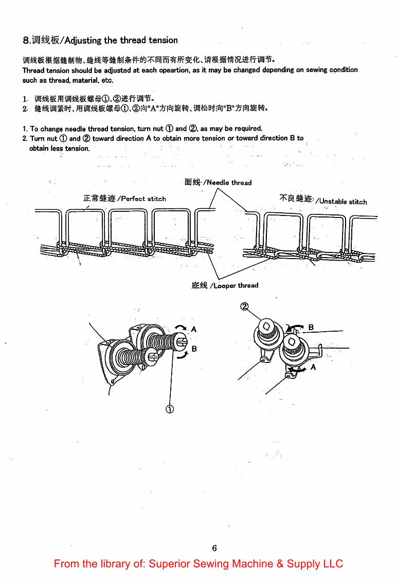
Adjusting the thread tension
Thread tension should be adjusted at each opeartion, as it may be changed depending on sewing cpnditionsuch as thread, material, etc.
1.To change needle thread tension, turn nut ® and ®, as may be required.2. Turn nut ® and ® toward direction A to obtain more tension or toward direction B to
obtain less tension.
/Needle thread
/Perfect stitch / \ ^^^^VUnstable stitcht • •' J • •
1?
/Looper thread
From the library of: Superior Sewing Machine & Supply LLC

9.ffMffi^fitfiJil^/Adjusting the presser foot pressure
C
B
U
r
y±. OU
1.
1. Presser foot pressure is adjusted by thumb screw.2. Turn adjust screw ® toward direction A to
increase pressure and toward direction B todecrease pressure.
tf^EE;tl6tlW^/A(Jiustingthe roller pressure
1.
1. Presser foot pressure is adjusted by thumb screw.2. Turn adjust screw ® toward direction A to
increase pressure and toward direction B todecrease pressure.
From the library of: Superior Sewing Machine & Supply LLC

10.iM^3^iii®ilSS/Adjusting the hight of the feed dog
When the needle bar is at its lowest position, full depth of teeth should project 1.0 mm above upper surfaceof throat plate, and the top of the teeth should be parallel with throat plate.
1.
2.
• 3ll?l3^6^7R¥Tii!i
N 1.
6^7jc^'feSo3.
• Setting the height of feed dog
1. To adjust the height, remove throat plate andtilt machine back on its hinges.
2. Loosen nut ® and Sfcrew @ and adjust feed dogheight by screw ®.
In lowering feed dog position, depress the
top surface of the teeth downward.
3. When correct height is obtained, tighten screw ^and nut (D securely.
• Setting the horizontal of feed dog
1.To obtain horizontal of feed dog, loosen screw ©and make an adjustment
2. When the feed dog position is set correctly,pinch screw © securely.
8
From the library of: Superior Sewing Machine & Supply LLC
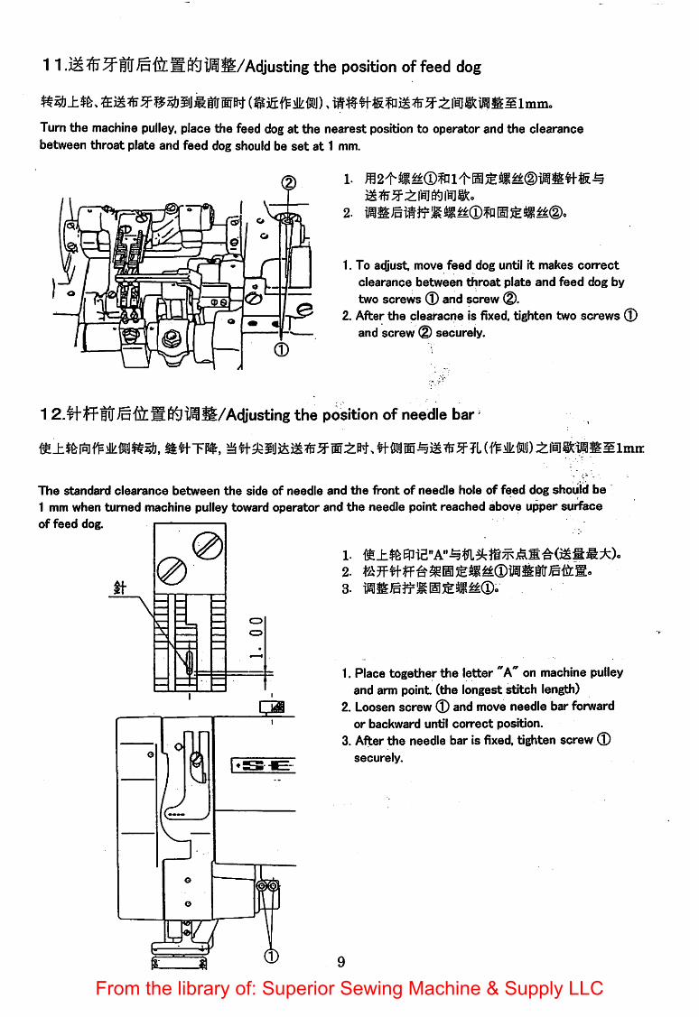
11 .M^iT3^H!r®'feBtei^S/Adjusting the position of feed dog
Turn the machine pulley, place the feed dog at the nearest position to operator and the clearancebetween throat plate and feed dog should be set at 1 mm.
1.
2.
1. To adjust, move feed dog until it makes correct
clearance between throat plate and feed dog by
two screws ® and screw (D.2. After the clearacne is fixed, tighten two screws ®
and screw ® securely.
1 Adjusting the position of needle bar '
The standard clearance between the side of needle and the front of needle hole of feed dog should be
1 mm when turned machine pulley toward operator and the needle point reached above upper surfaceof feed dog.
n-0
— —
— o
o
.
— —
1.
1. Place together the letter "k" on machine pulleyand arm point (the longest stitch length)
2. Loosen screw ® and move needle bar forwardor backward until correct position.
3. After the needle bar is fixed, tighten screw ®securely.
From the library of: Superior Sewing Machine & Supply LLC

1 S.^^fi^USS/Adjusting the looper position
0.05-0.2%
iSSSO.05—0.2mm^&S®.
1.feJF« [email protected]. iise.Jtmsss®-
S#i-4(f^>lk®DSaW,
1. ♦aff2-f^#fH««[email protected]^.
2.5mm
1.
2.
Clearance between looper and needle
The standard clearance between groove of needle and looper point should be 0.05-0.2mm.
1. To acQust looper position, loosen screw ® and move looper holder to get correct clearance.2, Tighten the looper holderscrew ® securely
Clearance between looper and loop deflector
The standard clearance between rightside of loopers and loop deflector should be 1.5mm when loopers are infront position.
1.To acOust clearance, loosen two screws d) and move loopers until correct position.2. After loopers are fixed, tighten two screws(D securely.
Looper position for back and forward movements
When pulley is turned toward the operator, looperpoint should pass the same position in groove ofneedle during forward and backward movements of looper.
1. To make this adjustment, loosen screw (D and, then change the position of loopercan by adjusting thetightness of two screws @ .
2. Tighten screw (3) and screws @ securely.
10From the library of: Superior Sewing Machine & Supply LLC
WAUltON
2.5"^
LooperNeedle
Needle guard
11
1.
2.
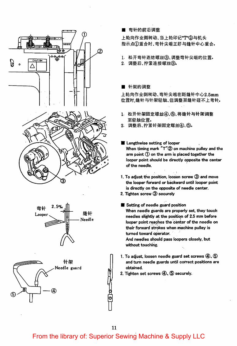
J:$&f^f^^{S'Jlt^. 55lilf4''Ci^2.5mm
2.
• Lengthwise setting of looperWhen timing mark "T'^® on machine pulley and thearm point 0 on the arm is placed together thelooper point should be directly opposite the center
of the needle.
1. To adjust the position, loosen screw ® and movethe looper forward or backward until looper point
is directly on the opposite of needle center.2. Tighten screw © securely
• Setting of needle guard positionWhen needle guards are properly set. they touch
needles slightly at the position of 2.5 mm before
looper point reaches the center of the needle on
their forward strokes when machine pulley is
turned toward operator.And needles should pass loopers closely, butwithout touching.
1. To adjust loosen needle guard set screws ®and turn needle guards until coirect positions are
obtained.
2. Tighten set screws @s ® securely.
From the library of: Superior Sewing Machine & Supply LLC
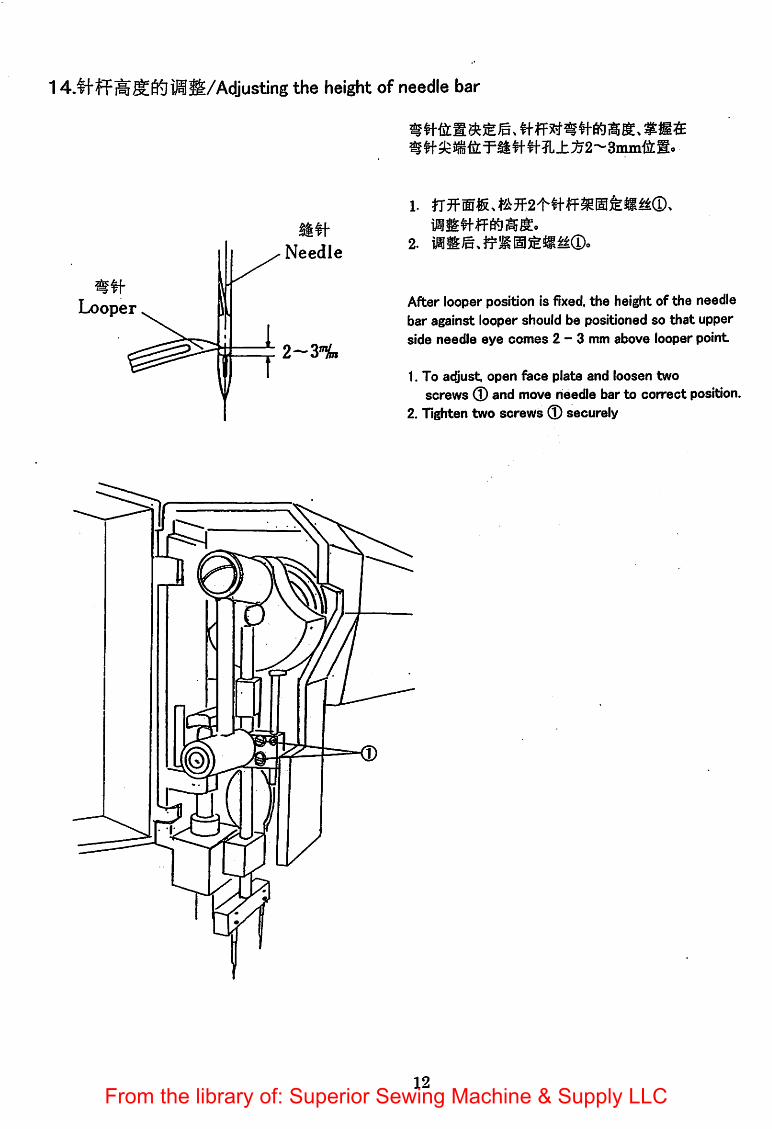
1iMS/Adjusting the height of needle bar
Needle
Looper
2~y%i
1
#f ff #S4
1.
1IS#|-fF«iii5g.2. iiS©,fi=Ka5t!li^®.
After looper position is fixed, the height of the needlebar against looper should be positioned so that upperside needle eye comes 2-3 mm above looper point
1. To adjust open face plate and loosen twoscrews 0 and move needle bar to correct position.
2. Tighten two screws ® securely
12From the library of: Superior Sewing Machine & Supply LLC
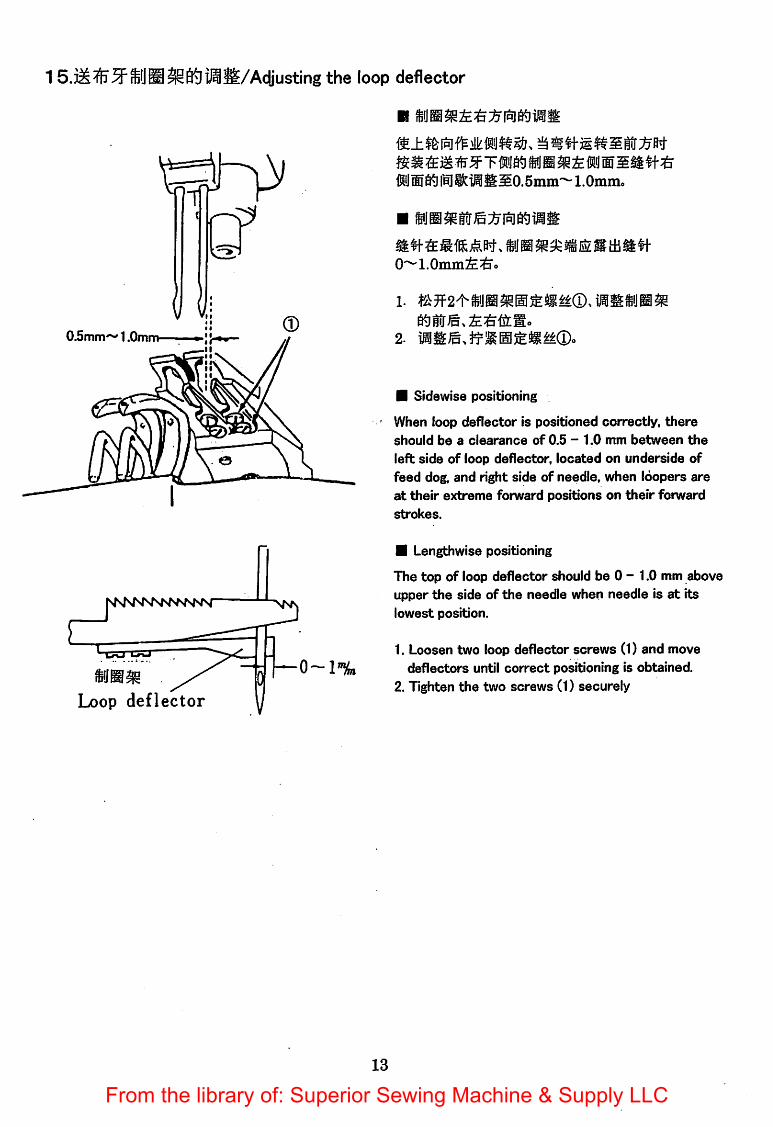
15.iM^5F®J®SiStljM&/Adjusting the loop deflector
0.5mni—1.0mm
Loop deflector
0-1%
ftJnd^lBjltiifiSO.Smm'^l.Oinin.
0~1.0mm2E^o
2. iaiEe.yfS0S«M®.
• Sidewise positioning
When loop deflector is positioned correctly, there
should be a clearance of 0.5 - 1.0 mm between the
left side of loop deflector, located on underside offeed dog, and right side of needle, when loopers areat their extreme forward positions on their forward
strokes.
• Lengthwise positioning
The top of loop deflector should be 0 - 1.0 mm aboveupper the side of the needle when needle is at itslowest position.
1. Loosen two loop deflector screws (1) and movedeflectors until correct positioning is obtained.
2. Tighten the two screws (1) securely
13
From the library of: Superior Sewing Machine & Supply LLC

1 e.S^^pPKliJiS/Adjusting the spreader
0.2-0.5%,
0.5—2'%,
aw.JSW-®jnse^/R5fea5;[email protected]
2. i@SEe,itlg0SS«®.
se^/nsi^sssiMw.fi^/R.^^#f-^«®fti)lWPi®iiS:^0.2~0.5mm.
a^/Kilji^W-WlSIPtiHS^&0.5-t2mm.
1.
2. ifflSe.ifSOfeSM®.
• Lengthwise positioning
When the point of needle on its downward strokereaches upper surface of looper, the clearance
between side of needle and spreader point should
be 1.5 mm.
1. To adjust loosen set screw ® and movespreader forward or backward to get correct position.
2. Tighten set screw ® securely.
• Sidewise positioning
Turn machine pulley and make clearance between
spreader point and left side of looper 0.2 - 0.5 mmwhen spreader point reaches its left side end.
• Height setting
The spreader point should pass above upper side oflooper at the clearance of 0.5 - 2 mm
1. To adjust loosen two screws ® and movespreader upward or downward to get correct position.
2. Tighten two screws (D securely.
14From the library of: Superior Sewing Machine & Supply LLC

17.^^:§^KjiJiS/Adjusting the thread guide
ffi5^ffa)±?t-. mm
n^atBfi5^s^^w. latiE.
®ife,
• Adjusting the needle thread guide
To increase the amount of thread drawn at the top
of the needle bar stroke, raise take-up ® or loosenguide screw and lower the guide ©.To decrease the amount reverse the adjustment by
lowering the take-up or raising the guide.i
• Adjusting the looper thread guide
To increase the amount of thread, loosen looperthread guide screw and looper thread take-up rod
screw. And move thread guide® and take-up rod® to the ieft To decrease the amount reverse theadjustment by moving thread guide and take-up rod
to the right
1 8.l3i^J£^0^$S/Adjusting the timing bert
15
1.
3.
1. Turn machine pulley toward operator until needlebar is at its highest point
2. Turn safety clutch pulley toward arm shaft untilallow mark on safety cluth pulley is directly
opposite the rim on the machine bed.3. Assemble timing belt to arm and safety cluth pulley.
From the library of: Superior Sewing Machine & Supply LLC

© SEIKO SEWING MACHINE CO., LTD.11-3. Imado 1<hoine,Taito-ku, Tokyo 111-8534, JapanTEU-i-S1-3-3872-6173,4(0verseas group)FAX:+8l-3-3873-6596
E-Maii:[email protected].]p/seik0001/
Part No. IM 60710 (012001)
From the library of: Superior Sewing Machine & Supply LLC