
Instruction Manual Chlorine Cells - ABB Group 1.0 INTRODUCTION Drinking water, cooling water and...
32
Instruction Manual IM/AW4SR Issue 1 Chlorine Cells T17KC4000AB Series
Transcript of Instruction Manual Chlorine Cells - ABB Group 1.0 INTRODUCTION Drinking water, cooling water and...

Instruction ManualIM/AW4SR Issue 1
Chlorine CellsT17KC4000AB Series

ABB
EN ISO 9001:2000
Cert. No. Q 05907
EN 29001 (ISO 9001)
Lenno, Italy – Cert. No. 9/90A
Stonehouse, U.K.
����
Electrical Safety
This equipment complies with the requirements of CEI/IEC 61010-1:2001-2 'Safety Requirements for Electrical Equipment forMeasurement, Control and Laboratory Use'. If the equipment is used in a manner NOT specified by the Company, the protectionprovided by the equipment may be impaired.
Symbols
One or more of the following symbols may appear on the equipment labelling:
Warning – Refer to the manual for instructions Direct current supply only
Caution – Risk of electric shock Alternating current supply only
Protective earth (ground) terminal Both direct and alternating current supply
Earth (ground) terminalThe equipment is protected through double insulation
The Company
We are an established world force in the design and manufacture of instrumentation forindustrial process control, flow measurement, gas and liquid analysis and environmentalapplications.
As a part of ABB, a world leader in process automation technology, we offer customersapplication expertise, service and support worldwide.
We are committed to teamwork, high quality manufacturing, advanced technology andunrivalled service and support.
The quality, accuracy and performance of the Company’s products result from over 100 yearsexperience, combined with a continuous program of innovative design and development toincorporate the latest technology.
The UKAS Calibration Laboratory No. 0255 is just one of the ten flow calibration plants operatedby the Company and is indicative of our dedication to quality and accuracy.
Information in this manual is intended only to assist our customers in the efficient operation of our equipment. Use of this manual forany other purpose is specifically prohibited and its contents are not to be reproduced in full or part without prior approval of theTechnical Publications Department.
Health and Safety
To ensure that our products are safe and without risk to health, the following points must be noted:
1. The relevant sections of these instructions must be read carefully before proceeding.
2. Warning labels on containers and packages must be observed.
3. Installation, operation, maintenance and servicing must only be carried out by suitably trained personnel and in accordance with the information given.
4. Normal safety precautions must be taken to avoid the possibility of an accident occurring when operating in conditions of high pressure and/or temperature.
5. Chemicals must be stored away from heat, protected from temperature extremes and powders kept dry. Normal safe handling procedures must be used.
6. When disposing of chemicals ensure that no two chemicals are mixed.
Safety advice concerning the use of the equipment described in this manual or any relevant hazard data sheets (where applicable) may be obtained from the Company address on the back cover, together with servicing and spares information.

1
TABLE OF CONTENTS 1.0 INTRODUCTION ..................................................................................................................... 2
1.1 General description..........................................................................................................................2 1.2 Model Number Breakdown ..............................................................................................................2 1.3 Standard accessories included with shipment .................................................................................3 1.4 Options and accessories..................................................................................................................3 1.5 Most common optional spare parts..................................................................................................3 1.6 Engineering specifications ...............................................................................................................3 1.7 Electrodes........................................................................................................................................4 1.8 Mounting dimensions.......................................................................................................................5
2.0 INSTALLATION....................................................................................................................... 7 2.1 Inspection ........................................................................................................................................7 2.2 Preliminary recommendation for installation ....................................................................................7
2.2.1 Sample line connection ............................................................................................ 10 2.2.2 Sample connection ................................................................................................... 10
2.3 Electrical connections ....................................................................................................................11 2.3.1 Measuring cell electrical connections...................................................................... 11 2.3.2 Buffer Feeder Mains Power ..................................................................................... 12
3.0 START-UP............................................................................................................................... 13 4.0 FUNCTIONAL DESCRIPTION ............................................................................................. 14 5.0 SAMPLE CONDITIONING DEVICES.................................................................................. 15
5.1 Measures of free residual chlorine.................................................................................................15 5.2 Measures of total chlorine..............................................................................................................16
6.0 MAINTENANCE .................................................................................................................... 17 6.1 Periodic functional check ...............................................................................................................17 6.2 Replacement of the copper electrode ............................................................................................17 6.3 Peristaltic Tube Replacement (Reagent Feed Systems Only) .......................................................18
7.0 TROUBLESHOOTING........................................................................................................... 19 8.0 PART LIST.............................................................................................................................. 20

2
1.0 INTRODUCTION Drinking water, cooling water and industrial water are usually disinfected with chlorine, chlorine dioxide or ozone. The level of disinfectant in these waters must be carefully controlled, since insufficient disinfection is to be avoided and too high chlorine concentrations lead to undesirable tastes and piping corrosion. A chlorine measuring cell like T17KC4000AB, connected to the AW400 transmitter, furnishes a chlorine analysing device and allows the automatic control of chlorine dosages in such systems. A chlorine measuring cell is available in the configuration standard (Mod. T17KC4400AB), with case IP66 (Mod. T17KC4200AB), with pH (Mod. T17KC4500AB) or ORP (Mod. T17KC4800AB), with both pH and ORP (Mod. T17KC4600). The instructions given herein cover general description, installation, operation and maintenance of the series T17KC4000AB sensor and accessories.
1.1 General description The application of this measuring system, consisting of a sensing device and a transmitter instrument, serves to the combined function of measuring, indicating and retransmitting the chlorine/chlorine dioxide/ozone concentration in a sample. The transmitter is ABB’s new AW400 series able to support up to three inputs. The sensor is an amperometric cell consisting of two concentric electrodes. The inner spiral is the gold measure electrode, the copper cylinder is the counter-electrode. The water sample flows into the electrodes chamber through nozzles that are located in the copper cylinder. A measured amount of a special Corundum sand placed into the cell is moved by the water and acts as an abrasive on the electrodes, keeping them sensitive. The measuring cell is provided with a differential pressure regulator filter, that maintains a constant water flow even in presence of input pressure fluctuations between 0.2 and 4.0 bar (2.9 and 58 psi). The signal is compensated for temperature variations through an integrated thermistor (PT100) that reads sample’s temperature.
1.2 Model Number Breakdown Measuring Cell Chlorine, Chlorine Dioxide, Ozone T17KC4 - 00 A B With pressure regulator and IP66 case 2 With pressure regulator 4 With pressure regulator and pH 5 With pressure regulator and pH & ORP 6 With pressure regulator and ORP 8 Fixed Code 00
Design level A
Fixed Code B

3
1.3 Standard accessories included with shipment • Corundum sand, (100 g bottle with dosing spoon) P/N 614L1425AB • Polyethylene flexible hose (3m, 3/8") for the sample inlet P/N 1D109C1025 • Wall mounting kit P/N 1T614B017U02 for T17KC4400AB/500AB/600AB/800AB; P/N 1D117F1005 for T17KC4200AB • Wall mounting bracket P/N 1T355C043U01 • Wall mounting instruction sheet P/N 1T338C00603AB • Tube fitting x 3/8" P/N 1T111G049U11, for T17KC4400AB/500AB/600AB/800AB
1.4 Options and accessories • Reagent feeder
- for FREE chlorine P/N 20988AB (120V) - for TOTAL chlorine P/N 20990AB (120V) - for FREE chlorine P/N 20989AB (240V) - for TOTAL chlorine P/N 20991AB (240V)
1.5 Most common optional spare parts
• Gold spiral electrode P/N 1D608B007U01 • Copper cylinder electrode P/N 1D321D1003 • Corundum sand (100g bottle with dosing spoon) P/N 614L1425AB • O-Ring P/N 101W702U01 • O-Ring P/N 101W705U01 • O-Ring P/N 101W792U01 • O-Ring P/N 101W909U01 • Sample inlet connection (3/8") P/N 1D668A014U01 • 1413-000 pH electrode for models 600AB and 500AB • 1184-600 ORP electrode for models 600AB and 500AB • 3m of cable for pH OR ORP sensors (Part No. 1401-500)
1.6 Engineering specifications • Electrodes: spiral gold measuring electrode, cylindrical copper counter-electrode. • Thermistor : PT 100. • Water sample pressure: 0.2 to 4.0 bar. For pressures over 4 bar install a pressure reducing valve. • Water flow : approximately 30 l/h (8 gal/h) for Mod. T17KC4200AB, and 50 l/h (13,2 gal/h) for Mod. T17KC4400AB/500AB/600AB/800AB. • Water sample temperature: compensated between 2 and 40 °C (35.6 and 104 °F) for T17KC4200AB/400AB/500AB/600AB/800AB. • Water sample pH (for free chlorine measures only): no correction is needed for pH ranging between 4.0 and 7.5 (Refer to Section 5.0). • Cell construction material: Electrodes : gold / copper. Electrodes chamber : plexyglass. Differential pressure regulator : PVC for T17KC4200AB/400AB/500AB/600AB/800AB. • Degree of IP protection: IP 66 (Mod. T17KC4200AB); IP 64 (Mod. T17KC4400AB/500AB/600AB/800AB). • Mounting dimensions (See Fig.1 and Fig.2, Section 1.8)
- Mod.T17KC4200AB: 263 (h) x 167 (l) x 135 (d) mm (10.3 x 6.6 x 5.3 in). - Mod.T17KC4400AB: 194 (h) x 160 (l) x 143 (d) mm (7.6 x 6.3 x 5.6 in). - Mod.T17KC4500AB/600AB/800AB: 269 (h) x 160 (l) x 143 (d) mm (10.6 x 6.3 x 5.6 in).
• Shipping weight: 3 kg (6.6 lb).
4
1.7 Electrodes The cell is made of two concentric electrodes, the gold spiral electrode and the copper cylinder electrode. The sample water enters into the cell, in which a differential pressure regulator maintains a constant water flow even in presence of input pressure fluctuations between 0.2 and 4.0 bar (2.9 and 58 psi). The water sample enters tangentially in the electrode chamber and the gritting action of the sand keeps the electrodes sensitive. The presence of the sand allows long periods of operation without necessity of maintenance on the cell. The cell widens upwards so allowing the sand to drop into the hydraulic low pressure section and recycle down in the electrode chamber. An integrated filter prevents the loss of sand through the overflow that may occur in cases of excessive air bubbling through the cell. Model T17KC4200AB includes an integrated check-valve located in the inlet fitting to prevent water loss when sampling pump is stopped. Models T17KC4500AB/600AB/800AB also include pH and/or ORP electrodes (ABB PART Nos. 1413-000 and 1184-600) and 3m of cable (ABB Part No. 1401-500). The sample flows into a sensor’s inner chamber where pH/ORP electrodes and PT100 thermistor are submerged.

5
1.8 Mounting dimensions
Fig. 1 Mod. T17KC4400AB/500AB/600AB/800AB, Mounting dimensions
Fig. 2 Mod. T17KC4200AB, Mounting dimensions

6
Fig. 3 Free Chlorine Reagent Feeder (P/N 20988AB-120 volt; 20989AB-240 volt), Mounting dimensions
Fig. 4 Total Chlorine Reagent Feeder (P/N 20990AB-120 volt; 20991AB-240 volt), Mounting dimensions

7
2.0 INSTALLATION
2.1 Inspection ABB takes all possible precautions in packing each equipment item to prevent damages during shipment. However it's advisable to carefully inspect each item and, if damage has occurred, report it immediately. Damage claims should be reported to the shipping agent involved for the equipment. Do not install any equipment if damage is such that faulty operation is likely to result. Carefully inspect all packing material before discarding it to prevent loss of mounting hardware, accessories, spare parts or instructions.
2.2 Preliminary recommendation for installation Perform the following checks before proceeding to the installation, to make sure that the probe will be free of malfunctions and damages: - make sure that the cell construction material (See Engineering Specifications) is suitable to the sample
chemical composition. - make sure that the process and environmental temperature are within specified limits (See Engineering
Specifications). Select the location of installation in order to comply the following requirements: - the sampling point should be significant for the process control. - it should be comfortable for the maintenance operations. - it should be completely free of vibrations. - it should be as far as possible from rotating or electrical commutation devices. - the cell should not be exposed to direct sunlight. - Air bubbles in the sample, if they are frequent and with large dimensions, may disturb the correct reading
making it unstable. - calibration must be performed with the AW400 transmitter (See AW400 Instruction Manual).

8
Fig. 5 Suggested installation without reagent feeder
Fig. 6 Suggested installation with reagent feeder
Total Chorine Free Chorine

9
Preparation before the installation The measuring cell family T17KC4000AB is normally wall mounted. Mounting hardware is supplied. Attach Mod.T17KC4200AB to the wall with the 4 supplied mounting screws through the 4 mounting holes. Fix Mod.T17KC4400AB/500AB/600AB/800AB through the 2 holes in the back side of the instrument. Two mounting screws are supplied. The T17KC4000AB series measuring cell can be used with or without the optional reagent feeder. No reagent feeder When installing the measuring cell without the reagent feeder option, be sure to attach the supplied shunt tubing assembly (a, Fig. 7) to the two fittings located on the right side of the measuring cell assembly for Mod. T17KC4400AB/500AB/600AB/800AB, on the left side for Mod. T17KC4200AB. Complete the assembly by installing the rectangular mounting bracket to the back of the measuring cell using the supplied screws. Free Chlorine Reagent Feeder When installing the measuring cell with the Free Chlorine Reagent Feeder, be sure to attach the supplied Free Chlorine reagent tubing assembly (b, Fig. 7) to the two fittings located on the right side of the measuring cell assembly for Mod. T17KC4400AB/500AB/600AB/800AB, on the left for Mod. T17KC4200AB. Connect the attached tube (b1, Fig. 7) to the barb on the outlet side of the peristaltic pump. The shunt tube (a, Fig. 7) should be saved in the event that the application changes and the reagent feeder becomes unnecessary. Set aside the rectangular mounting bracket and install the square mounting bracket furnished with the reagent feeder panel to the back of the measuring cell using the supplied screws. Complete the assembly by fastening the rectangular mounting bracket and cell to the reagent feeder panel using the supplied screws. Remove the tubing assembly from the supplied 30.2 l (8 gal) reagent container. Insert the weighted end of the tubing assembly into the container and connect the other end to the barb on the inlet side of the peristaltic pump.
Fig. 7 Measuring Cell Tubing Connection

10
Total Chlorine Reagent Feeder When installing the measuring cell with the Total Chlorine Reagent Feeder, be sure to attach the supplied Total Chlorine reagent tubing assembly (c ,Fig. 7) to the two fittings located on the right side of the measuring cell assembly for Mod. T17KC4400AB/500AB/600AB/800AB, on the left for Mod. T17KC4200AB. Connect the attached tubes (c1, c2, Fig. 7) to the two barbs on the outlet side of the peristaltic pump. Set aside the rectangular mounting bracket and install the square mounting bracket furnished with the reagent feeder panel to the back of the measuring cell using the supplied screws. Complete the assembly by fastening the rectangular mounting bracket and cell to the reagent feeder panel using the supplied screws. Remove the tubing assemblies from each of reagent containers. Insert the weighted ends of the tubing assemblies into the containers and connect the other ends to the barbs on the inlet side of the peristaltic pump.
2.2.1 Sample line connection Sufficient water sample pressure must be available so that the water transfer time is as short as possible, to reduce system time lag. For pressure over 4 bar install a pressure reducer and set pressure into the allowable range (typically 2 bar). When the sample enters the cell for gravity allow a minimum hydraulic head of two meters. Use polyethylene tubing or PVC piping for water sample transfer. WARNING !
The soft overflow tube must not be shortened and must drain freely without back pressure. Do not discharge water sample in metal piping as corrosion may occur.
The transmitter should be located near the cell and over it, for convenience in the periodic calibration. Connect the transmitter according to the instructions given in the Instruction Manual pertinent of the AW400.
2.2.2 Sample connection To connect the sample line use a polyethylene or flexible PVC tubing, with external diameter 3/8". In Mod.T17KC4200AB take off the frontal cover and pull out the ball headed pin on the lower part of the front panel. Pull downwards the PVC fitting and unscrew its lower nut. Insert the nut in the hose and insert the hose end in the PVC fitting. Insert the PVC fitting in its housing. Replace pin to hold the inlet fitting. In Mod. T17KC4400AB/500AB/600AB/800AB unscrew the adapter on the lower part of the cell, insert the hose and replace the adapter. Insert the drain hose about 10 - 15 cm (3.9 – 5.9 in) in a non-metal pipe. In this way an easy hose removal is allowed for sample collection which is necessary for periodic calibration.

11
2.3 Electrical connections
2.3.1 Measuring cell electrical connections Connect the measuring cell to the transmitter as described in the transmitter’s Instruction Bulletin. The T17KC4000AB sensor is supplied with cables for the measuring cell and for the PT100 thermistor.
Fig. 8 Electrical Connections of the Measuring Cell
The measuring cell is connected to terminals 3 and 4 on the AW400 analog input/output board and the ground wire is connected to terminal 4 of the power terminal board (Fig. 8). The optional pH and/or ORP probes are connected to terminals 5 and 6 (separate input cards required), the PT100 is connected to terminals 7, 8 and 9 of the appropriate analog input/output board (Fig. 8). The cell wires are marked with terminal designations 3, 4 and G and the PT100 wires are marked 7,8, and 9.
1 2 3 4 L1 N G G*
AW400 analog Input/Output board
* Ground Wire T17KC4000AB
AW400 power terminal board
Output mA
mV input pH,
ORP
PT100 Thermistor
TK17KC4000AB μA Input

12
2.3.2 Buffer Feeder Mains Power The buffer feeder pump requires a single-phase power source. The buffer feed motor can be wired to either a 110 VAC or 220/240 VAC supply as appropriate. All models require a cable and plug to be fitted before use. The voltage to ground from either pole of the power source must not exceed the maximum rated operating voltage, 130 for 110 VAC supply or 264 VAC for the 220-240 VAC supply. Before making connection to the power source, determine that the voltage of the power source is correct. The power source must have a fuse or circuit breaker rated no higher than 1 A, and be supplied via a suitable disconnection device i.e. a switch. To fit a power cable to the buffer feed pump, unscrew the 4 retaining screws on the buffer pump assembly. Locate the 3 wires attached to the buffer feed motor and identify the two black leads as shown below in Fig.9 (L1 and L2). Attach a suitable power lead to the motor leads as local regulations permit. Connect the power lead earth ground to the side case of the motor as shown in Fig. 9, pass the power lead through the cable gland and tighten the gland, this ensures a waterproof and robust seal around the power lead. Reassemble the enclosure ensuring no wires or leads are trapped.
Fig. 9 Sensing module power connections

13
3.0 START-UP Check the entire installation is connected properly. Open all valves in the sample water line and wait till the water flows steadily from the overflow tube. Stop the water flow. Open the cell body cover pulling it up with a twisting motion. Pour into the water in the cell ONE LEVELLED SPOON of the supplied Corundum sand. Replace the cover and restart the water flow. Check water sample flow collecting the overflow water in a graduated vessel. A 1/2 l (0.13 gal) vessel should be filled in 55-65 sec for T17KC4200AB, in 20-30 sec for all other models (T17KC4400AB/500AB/600AB/800AB). This is the correct water flow in order to keep the Corundum sand working. Now the cell is ready for operation. Open the sample flow and wait about 24 hours before starting the calibration, since the electrodes working surfaces require time for stabilisation. WARNING !
The calibration has to be performed at the start up in the presence of the AW400 transmitter. Please find the instructions related to the procedure in the Instruction Manual of AW400.
All the substitutions or the cleaning of the electrodes require a new start-up: always make sure the required amount of Corundum sand is swirling in the body. WARNING !
Never ADD Corundum sand in the body, but always CHANGE it completely.

14
4.0 FUNCTIONAL DESCRIPTION The measuring cell T17KC4000AB is an electrochemical cell and it is polarized because of the normal potential of the two different metal electrodes. When an oxidising substance (chlorine/chlorine dioxide/ozone/bromine) is present in the sample between the electrodes, the measuring (gold) electrode is depolarised and the counter-electrode (copper) dissolves as Cu++. In the process of the reaction, electrons transfer from the copper electrode to the gold electrode through an electrically conducting path as an electric current. The number of electrons that move from an electrode to another is the same as that of electrons that are captured by chlorine/chlorine dioxide/ozone at the measuring electrode. So the cell generates a signal (current) which is proportional to the chlorine/chlorine dioxide/ozone concentration in the sample. The signal is compensated for temperature variations via software in the AW400 transmitter through a PT100 thermistor. The transmitter works out a digital signal of sample’s chlorine/chlorine dioxide/ozone concentration and a proportional current signal between 4-20 mA.

15
5.0 SAMPLE CONDITIONING DEVICES Measurements of total chlorine require sample conditioning devices. Sometimes they are also needed for free residual chlorine measurements. For chlorine dioxide/ozone/bromine measurements the sample conditioning is not necessary.
5.1 Measures of free residual chlorine Normally the measure of free chlorine with this analyser doesn't require any sample conditioning. However, when the sample pH is fluctuating or it is vastly high, a pH buffering solution is required. Fig.10 shows the allowable pH fluctuations in the sample, as a function of the pH value of the sample.
pH F
LUC
TUAT
ION
S
SAMPLE pH
Fig. 10 Allowable pH Fluctuation Envelope
When the pH increases over 6.0 the allowable variations decreases to approximately 0.5 pH units or less; the higher the pH value the lower the allowable fluctuations. In such cases, and always when the sample pH is over 7.5, a special additive is required for pH control. ABB supplies the complete feeder system, able to dose the right amount of buffer solution. It is represented in Fig 6.
− For Free Chlorine P/N 20988AB (120 VAC) − For Free Chlorine P/N 20989AB (240 VAC)
Shaded Area = conditions requiring pH buffering solution.

16
To prepare pH buffer (Acetic acid solution) follow these instructions: 1. Weight 2430 g (5.36 lb) of sodium acetate tri-hydrate (CH3COONa-3H2O) and dissolve completely in 4 l
(1 gal) of distilled water. 2. Add, while mixing, 4800 g (10.58 lb) of glacial acetic acid (98-100 % CH3COOH). 3. Mix thoroughly, then add distilled water to obtain 10 l (2.6 gal) of solution. The pH value of this solution is about 4.3 at 20 °C (68 °F). The buffer may be transferred to the 30,2 l (8 gal) container (marked Acetic Acid) provided with the reagent feeder. The buffer’s consumption is approximately 10 liters (2,6 gal) in 30 days. IMPORTANT:
Use only pure chemicals. Use only polyethylene or glass vessels, other materials may be corroded, causing errors in measure. Do not use dirty reagents, or reagents in presence of a solid deposit.
5.2 Measures of total chlorine
The measuring cell T17KC4000AB allows total chlorine measurements by simply conditioning the sample with reagents. ABB supplies a reagent feeder, able to dose the right amount of buffer solutions (See Fig. 6)
− For Total Chlorine P/N 20990AB (120 VAC) − For Total Chlorine P/N 20991AB (240 VAC)
The reagent feeder is supplied with two 30.2 l (8 gal) for each container (marked “Acetic Acid” and marked “Potassium Iodide and Sodium Hydroxide”). Fill up the containers with the solutions prepared like following instructions: Reagent #1 (Acetic acid solution) Follow the same instructions as those reported in Section 5.1 to prepare pH buffer. Reagent #2 (Potassium Iodide and Sodium Hydroxide Solution)
1. In the 30,2 l (8 gal) container marked “Potassium Iodide and Sodium Hydroxide” (Reagent #2), dissolve 454 g (1 lb) of sodium hydroxide pellets in 15.15 l (4 gal) of distilled or deionized water.
2. When the sodium hydroxide has cooled to ambient temperature, add the required quantity of potassium iodide (See table below).
3. Mix by stirring the solution with a PVC or polyethylene rod. Solution comsumption is approx 10 l (2,6 gal) in 30 days.
Range (ppm) Potassium Iodide (g) 0 – 0.25 37.5 [1.32 oz] 0 – 0.50 75 [2.64 oz] 0 – 1.0 150 [5.29 oz] 0 – 2.0 300 [10.58 oz] 0 – 5.0 750 [1.65 lb]
0 – 10.0 1500 [3.30 lb]

17
6.0 MAINTENANCE
6.1 Periodic functional check The measuring cell, like other analyzers, should be checked once a week to assure the best measurement accuracy.
6.2 Replacement of the copper electrode If the cell sensitivity is vastly reduced it may be an indication of copper electrode damage. To replace it see the following instructions.
1) Stop the sample flow. 2) Only for Mod. T17KC4200AB remove the cover. 3) Remove both signal leads at the cell. 4) Pull the gold electrode fitting in the cell downwards, thereby exposing the entire electrode chamber;
the Corundum sand falls out with the water contained in the cell, and will have to be replaced. 5) In order to eliminate all the sand replace in a loose position the inferior part of the cell (gold electrode
fitting) and open the water sample. Refill the chamber and then remove the part quickly permitting the water to drain. When it's not possible, pull out the cell cover and flush the open cell with a squirt bottle filled with distilled or clean water. Sand prevents good O-ring sealing and must be completely removed.
6) Remove the knurled nut on the cell body. 7) Remove the holding screw from the copper electrode. Now the copper electrode can be removed by
lightly tapping on a soft surface. Replace the copper electrode with a new one if necessary. 8) Put back the holding screw in its position. Make sure the sealing surfaces and tight fits are free of
sand. In case they are not flush away any sand as described in the preceding paragraph. 9) Reposition the gold electrode assembly. 10) Add one levelled spoon of Corundum sand. 11) Close the cell and attach tubing assemblies and electrical connections.
18
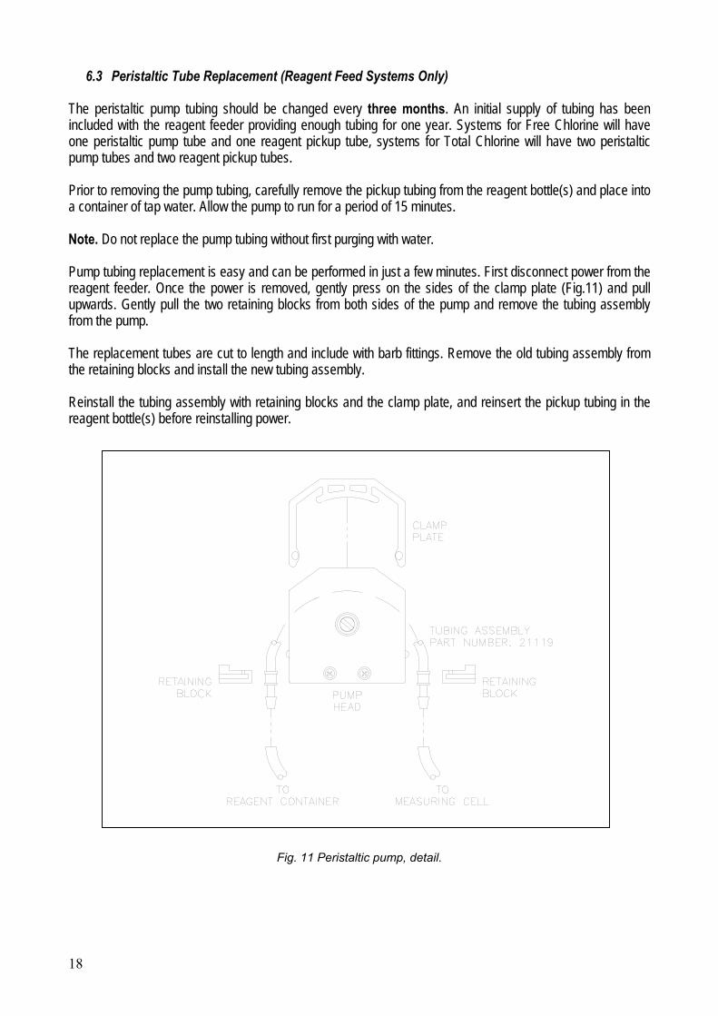
6.3 Peristaltic Tube Replacement (Reagent Feed Systems Only) The peristaltic pump tubing should be changed every three months. An initial supply of tubing has been included with the reagent feeder providing enough tubing for one year. Systems for Free Chlorine will have one peristaltic pump tube and one reagent pickup tube, systems for Total Chlorine will have two peristaltic pump tubes and two reagent pickup tubes. Prior to removing the pump tubing, carefully remove the pickup tubing from the reagent bottle(s) and place into a container of tap water. Allow the pump to run for a period of 15 minutes. Note. Do not replace the pump tubing without first purging with water. Pump tubing replacement is easy and can be performed in just a few minutes. First disconnect power from the reagent feeder. Once the power is removed, gently press on the sides of the clamp plate (Fig.11) and pull upwards. Gently pull the two retaining blocks from both sides of the pump and remove the tubing assembly from the pump. The replacement tubes are cut to length and include with barb fittings. Remove the old tubing assembly from the retaining blocks and install the new tubing assembly. Reinstall the tubing assembly with retaining blocks and the clamp plate, and reinsert the pickup tubing in the reagent bottle(s) before reinstalling power.
Fig. 11 Peristaltic pump, detail.

19
7.0 TROUBLESHOOTING SYMPTOM PROBABLE CAUSE CHECK ACTION CORRECTIVE ACT. Unstable or Copper electrode Visual inspection Clean or replace the erratic corroded or dirty copper electrode indication Too much or too Verify Clean the electrodes small qty. of Corundum cell and add the sand correct quantity of fresh Corundum sand Electrical contact not Verify Secure the sufficient connections Excessive air bubbles Visual inspection Eliminate the cause in the sample in the drain hose Reversed electrical Verify Make correct connections connections to the electrodes Faulty thermistor Verify with tester Replace thermistor assembly Broken or loosen Verify Replace or make wires secure connections Sample pressure or flow Verify Correct the cause rate not sufficient Faulty transmitter Verify, according to Repair or send to ABB Instruction Bulletin Calibration required Verify, according to Perform calibration Instruction Bulletin

20
8.0 PART LIST
Fig. 12 T17KC4200AB sensor, P/N 1T803C017U01
14
4
Dwg:1T-SD-17-0074.

21
Part List, T17KC4200AB sensor, P/N 1T803C017U01 (See Fig.12) ITEM DESCRIPTION PART NUMBER 1 Regulator 1D806D005U01 2 Cable, 1.2 m 1T677B121U01 3 Inlet valve 1D668A014U01 4 Screw M4x55 1T396B006U01 5 Pin 1D643A001U01 6 Thermistor 1T610B019U01 7 Complete cell assembly (see page 24) 1D610A1021 8 Orifice 1D356B007U01 9 / / 10 Cover plate 1D625B001U01 11 Case 1D323C006U01 12 / / 13 Grommet 1T104B008U01 14 Nut 1T397A007U01 15 Plug 1D109E007U01 16 Rubber plating 1D104B001U03 17 Transparent hose 1T361B006U01 18 O-Ring 101W795U01 19 / / 20 O-Ring 101W705U01 21 Flexible hose 1T361B006U02 22 / / 23 Washer 1T085A012 24 Cylindrical screw M4x10 1T004E003T60 25 / / 26 Cylindrical screw M5x45 1D009H121AU20 27 Cylindrical screw M5x12 1D005H109AU30 28 Headless screw M3x5 1D017F105AU20 29 / / 30 Pipe 1T361B005U03 31 Pipe 1T361B005U04

22
Fig. 13 T17KC4600AB sensor P/N 1T-BM-17-0019
Dwg: 1T-SD-17-0082
Fig. 14 T17KC4400AB sensor P/N 1T-BM-17-0019
Dwg: 1T-SD-17-0080.

23
Fig. 15 Sensor T17KC4500AB/4800AB P/N 1T-BM-170019
Dwg: 1T-SD-17-0081
Part List, T17KC4400AB/500AB/600AB/800AB sensor P/N 1T-BM-17-0019 (See Fig. 13, Fig. 14 and 15) ITEM DESCRIPTION PART NUMBER 1 Regulator assembly, for T17KC4400AB/500/600/800 1T806D011U01 1 Regulator assembly, for T17KC4700AB 1T806D011U02 2 Complete cell assembly 1T610A002U01 3 Support 1T355C043U01 4 Screw M4x20 TSP 1T005C007T60 5 Tag of identification 1T338B047U01AB 6 Tag of the logo 1T338D067U01AB 7 O-ring 101W905U01 8 Inlet pipe 1D371B028U01 9 Plug PG 13.5 1T366B013U04 10 Thermistor assembly 1T168D026U01 11 Cable assembly 1T677B122U01 12 Screw TEI M5x45 steel 1D009H121AU20 13 O-ring 101W705U01 14 Screw M4x8 TCP 1T004E002T60 15 Washer diam. 4.3 1T085A012 16 Strip 1T117F021U01 17 Cable glands 1T104B009U04 18 pH electrode assembly 1413-000 19 ORP electrode assembly 1184-600 20 Mounting kit case 1T614B017U02 21 Corundum sand (100 g) (not shown) 614L1425 22 Pipe diam. 3/8" polyethylene for sample line (not shown) 1D109C1025MT
19
green
white

24
Fig. 16 Measuring cell (Mod. T17KC4200AB) P/N 1D610A1021
Dwg: 1D610A1021 Part List, Measuring cell, (Mod. T17KC4200AB) P/N 1D610A1021 (See Fig.16) ITEM DESCRIPTION PART NUMBER 1 Pin 1D394A1005 2 Pin 1D394A1004 3 Electrode head 1D322D1082 4 Cover 1D641A001U01 5 Cell body 1D322D1080 6 Gold electrode 1D608B007U01 7 Copper electrode 1D321D1003 8 O-Ring 101W909U01 9 O-Ring 101W792U01 10 / / 11 O-Ring 101W702U01 12 Washer 1T085A010 13 Knurled nut (M3) 1D075F100AU30 14 Nut (M3) 1T082A104T60 15 Washer 085D006T10 16 Corundum sand (not shown) 614L1425

25
Fig. 17 Measuring cell (Mod. T17KC4400AB/500AB/600AB/800AB) P/N 1T610A002U01
Dwg: 1T610A002U01 Part List, Measuring cell (Mod. T17KC4400AB/500AB/600AB/800AB) P/N 1T610A002U01 (See Fig.17) ITEM DESCRIPTION PART NUMBER 1 Pin 1T398A002U01 2 Pin 1T398A003U01 3 Electrode head 1T322D048U01 4 Cover 1T641A004U01 5 Cell body 1T322D047U01 6 Gold electrode 1D608B007U01 7 Copper electrode 1D321D1003 8 O-Ring 101W909U01 9 O-Ring 101W792U01 10 O-Ring 101W702U01 11 Washer 1T085A010 12 Knurled nut 1D075F100AU30 13 Screw 1T082A104T60 14 Washer 085D006T10

26
Fig. 18 Differential pressure regulator (Mod. T17KC4200AB) P/N 1D806D005U01
Dwg:1D806D005U01 Part List, Differential pressure regulator (Mod. T17KC4200AB) P/N 1D806D005U01 (See Fig.18) ITEM DESCRIPTION PART NUMBER 1 Valve 1D668A001U01 2 Body top 1D433A1031 3 Body bottom 1D433A015U01 4 / / 5 Valve seat 1D433F1021 6 Membrane 425B025F80 7 Spring 1D424A1041U02 8 Spring 1D424A1042 9 Nut 1D403A1006 10 Regulating screw 1D396C1084 11 Membrane plate 1D391G1011 12 Ring 391G050U01 13 / / 14 Elbow, 90° 1D112K1020 15 Connecting elbow 1D110B1049 16 / / 17 / / 18 Regulating screw 1D396G004U01 19 / / 20 / / 21 O-Ring 101W711U01 22 O-Ring 101W705U01 23 Cylindrical screw M6x50 1D009J122AU20

27
Fig.19 Differential pressure regulator (Mod. T17KC4400AB/500AB/600AB/800AB) P/N 1T806D011U01/U02
Dwg:1T806D011U01/U02 Part List, Differential pressure regulator (Mod. T17KC4400AB/500AB/600AB/800AB) P/N 1T806D011U01 (See Fig.19)
ITEM DESCRIPTION PART NUMBER 1 Screw (cylindrical head) M6 x 30 1T006E009 T60 2 Back body 1T433A016 U01 3 Spring 1D424A1042 4 Back pigeon 1T391G030 U01 5 O-Ring 101W712 U01 6 Membrane 1T425B010 U01 7 Front pigeon 1T391G029 U01 8 O–Ring 1T101W011 U01 9 Washer ø 10 1T085A055 T60
10 Bolt (hexagonal head) M10x14 1T397D025 U01 11 Valve seat 1D433F1021 12 Front body 1T433A015 U01 13 Valve pin assembly 1D668A001 U01 14 Spring 1D424A1041 U01 15 Regulation screw 1D396C1084 16 O–Ring 101W711 U01 17 Plexiglas disk 1D374B004 U01 18 O–Ring 101W913 U01 19 Washer ø 4.3 1T085A012 20 Screw (cylindrical head) M4x8 1T004E002 T60 21 Plug 1/8” x ø 6 1T111G046 U01 22 Pipe ø 6 1T361B005 U06 23 Orifice 1T356B002 U01 24 Plug ¼” NPT for pipe 3/8” 1T111G049 U11
1
24
1
3
4
6
78
9 10
11
12
17 18 21
23
20 19
13 1415 16
2
5
22"A"
"A"
"A"

28
Notes

PRODUCTS & CUSTOMER SUPPORT
Products
Automation Systems• for the following industries:
– Chemical & Pharmaceutical– Food & Beverage– Manufacturing– Metals and Minerals– Oil, Gas & Petrochemical– Pulp and Paper
Drives and Motors• AC and DC Drives, AC and DC Machines, AC Motors to
1kV• Drive Systems• Force Measurement• Servo Drives
Controllers & Recorders• Single and Multi-loop Controllers• Circular Chart and Strip Chart Recorders• Paperless Recorders• Process Indicators
Flexible Automation• Industrial Robots and Robot Systems
Flow Measurement• Electromagnetic Flowmeters• Mass Flowmeters• Turbine Flowmeters• Wedge Flow Elements
Marine Systems & Turbochargers• Electrical Systems• Marine Equipment• Offshore Retrofit and Refurbishment
Process Analytics• Process Gas Analysis• Systems Integration
Transmitters• Pressure• Temperature• Level• Interface Modules
Valves, Actuators and Positioners• Control Valves• Actuators• Positioners
Water, Gas & Industrial Analytics Instrumentation• pH, Conductivity and Dissolved Oxygen Transmitters and
Sensors• Ammonia, Nitrate, Phosphate, Silica, Sodium, Chloride,
Fluoride, Dissolved Oxygen and Hydrazine Analyzers• Zirconia Oxygen Analyzers, Katharometers, Hydrogen
Purity and Purge-gas Monitors, Thermal Conductivity
Customer Support
We provide a comprehensive after sales service via a WorldwideService Organization. Contact one of the following offices fordetails on your nearest Service and Repair Centre.
United KingdomABB LimitedTel: +44 (0)1235 512000Fax: +44 (0)1235 512020
Client WarrantyPrior to installation, the equipment referred to in this manual mustbe stored in a clean, dry environment, in accordance with theCompany's published specification.
Periodic checks must be made on the equipment's condition. Inthe event of a failure under warranty, the following documentationmust be provided as substantiation:
1. A listing evidencing process operation and alarm logs at time of failure.
2. Copies of all storage, installation, operating and maintenance records relating to the alleged faulty unit.

IM/A
W4S
R Is
sue
1
ABB has Sales & Customer Support expertisein over 100 countries worldwide
www.abb.com
The Company’s policy is one of continuous product improvement and the right is reserved to modify the
information contained herein without notice.
Printed in UK (06.07)
© ABB 2007
ABB Limited8 HawksworthSouthmead Industrial ParkDidcot, OxfordshireOX11 7HRUKTel: +44 (0)1235 512000Fax: +44 (0)1235 512020