INSTRUCTION MANUAL - ARENZ · INSTRUCTION MANUAL AMS 4000 – 230V ... AMS NPU’s are mostly used...
19
INSTRUCTION MANUAL AMS 4000 – 230V - Australia Manual Issue 1 – 01/10/12 Page 1 of 19 INSTRUCTION MANUAL AMS 4000 One Piece Negative Pressure Unit (AMS-4000 NPU 230V)
-
Upload
vuongkhanh -
Category
Documents
-
view
250 -
download
0
Transcript of INSTRUCTION MANUAL - ARENZ · INSTRUCTION MANUAL AMS 4000 – 230V ... AMS NPU’s are mostly used...
INSTRUCTION MANUAL AMS 4000 – 230V - Australia Manual Issue 1 – 01/10/12
Page 1 of 19
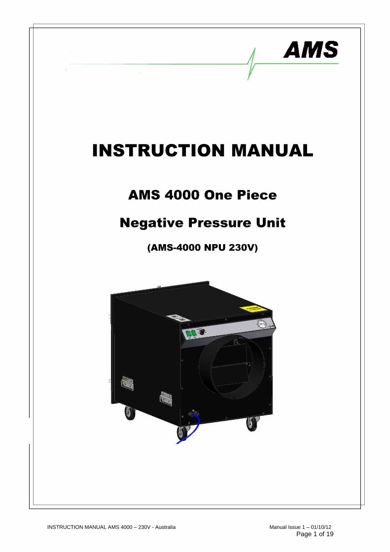
INSTRUCTION MANUAL
AMS 4000 One Piece
Negative Pressure Unit
(AMS-4000 NPU 230V)

INSTRUCTION MANUAL AMS 4000 – 230V - Australia Manual Issue 1 – 01/10/12
Page 2 of 19
WARNING
Asbestos exposure can cause severe and fatal diseases. Approved Code of
Practices should be applied at all times when using this equipment to ensure safe
working conditions.
About this Manual:
The purpose of this manual is to enclose all relevant information and data to this particular product and related
uses. This manual is to be utilised by the user of this product to ensure correct and safe methods are used
during related operations.
All Rights Reserved ©
Contents of this manual are not be copied or distributed by anyone without permission of the manufacturing
company of this product.
Manufactured by:
Air Management Systems Ltd Unit 1
9 Cannon Lane Tonbridge
Kent TN9 1PP
Tel: +44 (0) 1732 368359 Fax: +44 (0) 1732 368361
Web: www.ams-holdings.com
INSTRUCTION MANUAL AMS 4000 – 230V - Australia Manual Issue 1 – 01/10/12
Page 3 of 19
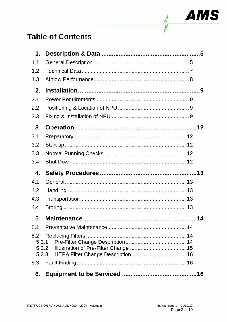
Table of Contents
1. Description & Data .......................................................... 5
1.1 General Description ............................................................... 5
1.2 Technical Data ....................................................................... 7
1.3 Airflow Performance ............................................................... 8
2. Installation ........................................................................ 9
2.1 Power Requirements ............................................................. 9
2.2 Positioning & Location of NPU ............................................... 9
2.3 Fixing & Installation of NPU ................................................... 9
3. Operation ........................................................................ 12
3.1 Preparatory .......................................................................... 12
3.2 Start up ................................................................................ 12
3.3 Normal Running Checks ...................................................... 12
3.4 Shut Down ........................................................................... 12
4. Safety Procedures ......................................................... 13
4.1 General ................................................................................ 13
4.2 Handling............................................................................... 13
4.3 Transportation ...................................................................... 13
4.4 Storing ................................................................................. 13
5. Maintenance ................................................................... 14
5.1 Preventative Maintenance .................................................... 14
5.2 Replacing Filters .................................................................. 14
5.2.1 Pre-Filter Change Description ........................................ 14
5.2.2 Illustration of Pre-Filter Change ..................................... 15
5.2.3 HEPA Filter Change Description .................................... 16
5.3 Fault Finding ........................................................................ 16
6. Equipment to be Serviced ............................................ 16
INSTRUCTION MANUAL AMS 4000 – 230V - Australia Manual Issue 1 – 01/10/12
Page 4 of 19
7. Accessories ................................................................... 17
7.1 Recommended Accessories ................................................ 17
7.2 Optional Extras .................................................................... 17
8. Technical System Information ..................................... 18
8.1 Wiring Diagram ..................................................................... 18
9. Test Reports ................................................................... 19
9.1 Airflow Tests ........................................................................ 19

INSTRUCTION MANUAL AMS 4000 – 230V - Australia Manual Issue 1 – 01/10/12
Page 5 of 19
1. Description & Data
1.1 General Description
AMS manufacture a range of “Negative Pressure Units” (NPU’s) to provide a powerful filtered air
extraction system. The NPU’s are mobile, easy to handle, install and operate. All NPU’s are
manufactured from durable, robust, safe and easy to clean materials.
AMS NPU’s are mostly used in the Asbestos Removal Industries in Europe and other countries
around the world that apply regulations to safely remove asbestos. The equipment is also used in
other industries to control environments where air contamination is a problem, including the nuclear
industry.
NPU’s are normally attached to a contained area (working enclosure) that is likely to become
contaminated during the maintenance or removal work. Extraction of filtered air will provide “Negative
Pressure” in the contained area preventing contamination to adjacent areas. In Europe and in other
parts of the world it is a regulation to use this equipment during the removal of asbestos materials.
AMS are specialist manufacturers of NPU’s and other equipment used for the European asbestos
removal industry. All equipment is manufactured to recognised European standards as well as
adapted for the specific local requirements of a particular country.
The AMS 4000 NPU provides a nominal airflow of 5200m3 /
hour (refer to test report section 9).
The standard NPU (AMS-4000) contains the following main components:
- Main Case Enclosure
- 2 Electric Motor Fans
- Pre-filter
- HEPA Filter
- Operation Control Instrumentation
- Pressure Difference Indicator (manometer)
- Speed Controller
For Optional Extras please refer to Section 7 of this manual
The NPU case is constructed from welded polypropylene, reinforced with welded polypropylene
internal ribs. Critical joints are ‘triple-welded’. Non-return flaps are fitted on the exhaust and the
Basic Unit has an On/Off Switch, a Speed Controller and a Pressure Drop Indicator (manometer
INSTRUCTION MANUAL AMS 4000 – 230V - Australia Manual Issue 1 – 01/10/12
Page 6 of 19
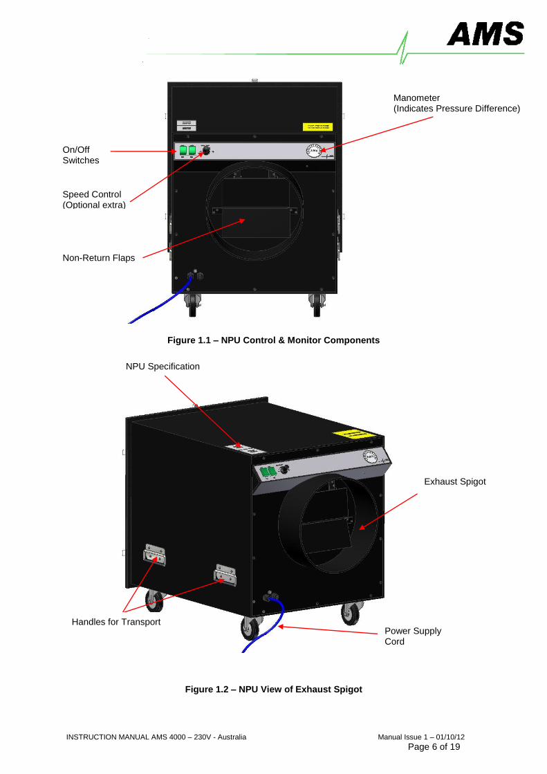
Figure 1.1 – NPU Control & Monitor Components
Figure 1.2 – NPU View of Exhaust Spigot
On/Off Switches
Manometer (Indicates Pressure Difference)
Non-Return Flaps
Exhaust Spigot
Handles for Transport
NPU Specification
Power Supply Cord
Speed Control (Optional extra)
INSTRUCTION MANUAL AMS 4000 – 230V - Australia Manual Issue 1 – 01/10/12
Page 7 of 19
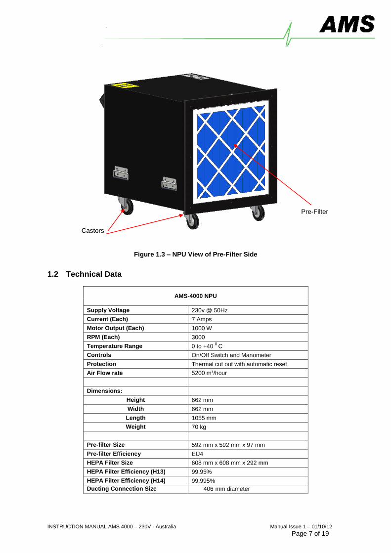
Figure 1.3 – NPU View of Pre-Filter Side
1.2 Technical Data
AMS-4000 NPU
Supply Voltage 230v @ 50Hz
Current (Each) 7 Amps
Motor Output (Each) 1000 W
RPM (Each) 3000
Temperature Range 0 to +40 0
C
Controls On/Off Switch and Manometer
Protection Thermal cut out with automatic reset
Air Flow rate 5200 m³/hour
Dimensions:
Height 662 mm
Width 662 mm
Length 1055 mm
Weight 70 kg
Pre-filter Size 592 mm x 592 mm x 97 mm
Pre-filter Efficiency EU4
HEPA Filter Size 608 mm x 608 mm x 292 mm
HEPA Filter Efficiency (H13) 99.95%
HEPA Filter Efficiency (H14) 99.995%
Ducting Connection Size 406 mm diameter
Pre-Filter
Castors
INSTRUCTION MANUAL AMS 4000 – 230V - Australia Manual Issue 1 – 01/10/12
Page 8 of 19
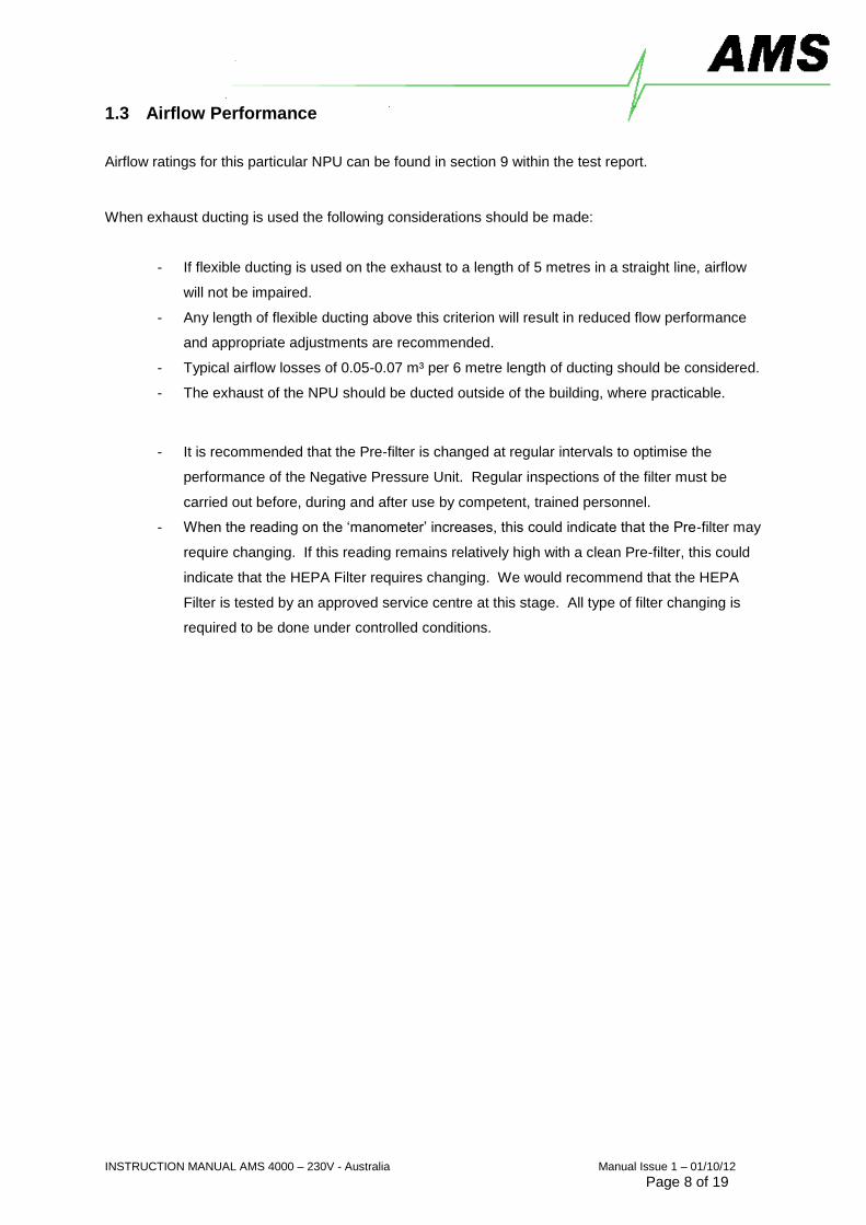
1.3 Airflow Performance
Airflow ratings for this particular NPU can be found in section 9 within the test report.
When exhaust ducting is used the following considerations should be made:
- If flexible ducting is used on the exhaust to a length of 5 metres in a straight line, airflow
will not be impaired.
- Any length of flexible ducting above this criterion will result in reduced flow performance
and appropriate adjustments are recommended.
- Typical airflow losses of 0.05-0.07 m³ per 6 metre length of ducting should be considered.
- The exhaust of the NPU should be ducted outside of the building, where practicable.
- It is recommended that the Pre-filter is changed at regular intervals to optimise the
performance of the Negative Pressure Unit. Regular inspections of the filter must be
carried out before, during and after use by competent, trained personnel.
- When the reading on the ‘manometer’ increases, this could indicate that the Pre-filter may
require changing. If this reading remains relatively high with a clean Pre-filter, this could
indicate that the HEPA Filter requires changing. We would recommend that the HEPA
Filter is tested by an approved service centre at this stage. All type of filter changing is
required to be done under controlled conditions.

INSTRUCTION MANUAL AMS 4000 – 230V - Australia Manual Issue 1 – 01/10/12
Page 9 of 19
2. Installation
2.1 Power Requirements
The AMS-4000 NPU utilises 2 electric motor fans to generate the reduced enclosure pressure and the
unit must be connected to a power supply capable of 16A continuous current. The 230V Negative
Pressure Units are supplied with two removable 5m power cords.
2.2 Positioning & Location of NPU Considerations should be made to which location the unit will be installed.
- The NPU should be located outside of the enclosure at all times
- The NPU should be positioned on a sturdy base to avoid unwanted movement of unit,
which could damage or break the seal between the NPU and enclosure.
- Consider exhaust ducting path if needed before connecting the NPU to enclosure.
- The unit shall be located in dry conditions, away from any water penetration or damp
environments, to avoid the unit or any of its components becoming wet.
- The power supply cables should be run in a manner that does not create a tripping
hazard and avoid locations where excessive traffic is present, which could result in unit
damage or injury.
- The unit should not be located externally to any buildings ideally. If this can not be
avoided then the unit shall be located within a waterproof enclosure.
2.3 Fixing & Installation of NPU
THE NEGATIVE PRESSURE UNIT SHOULD NOT BE INSTALLED INSIDE THE ENCLOSURE
- FAILURE to comply will result in contamination of the NPU’s clean side.

INSTRUCTION MANUAL AMS 4000 – 230V - Australia Manual Issue 1 – 01/10/12
Page 10 of 19
Example depicted in figure 2.1 – 2.3 applies to fixing and sealing a Negative Pressure Unit to a
polythene enclosure. The Filter End of the NPU should be outside of the enclosure, with the inlet
flange (Pre-filter inlet face) being taped to the polythene with cloth tape (refer to figures 2.2 & 2.3 to
follow).
- Position the Filter End of the NPU against the inside or outside of the enclosure.
- Mark and cut a hole in the enclosure around the Pre-filter to accommodate the unit
(figure2.2).
- Install the NPU against the opening and seal with conventional materials such as
Polythene and Tape.
- Install the Pre-filter (pleats aligned vertically) and tape the edges to the enclosure to make
a seal. The Pre-filter can then be changed without this seal between the enclosure and
the NPU being disturbed.
Figure 2.1 – NPU Positioned Outside Enclosure
NPU Positioned Outside Enclosure
Enclosure Wall
INSIDE OUTSIDE

INSTRUCTION MANUAL AMS 4000 – 230V - Australia Manual Issue 1 – 01/10/12
Page 11 of 19
Edges to be taped
from inside to form
seal between NPU
and Enclosure
(All 4 edges)
Figure 2.2 – Hole Cut to NPU Flange Size
Figure 2.3 – All Four Edges to be Sealed via Tape
Cut Enclosure along all four edges to Fit Flange of NPU allowing Area for Tape
Enclosure Wall
Enclosure Wall

INSTRUCTION MANUAL AMS 4000 – 230V - Australia Manual Issue 1 – 01/10/12
Page 12 of 19
3. Operation
3.1 Preparatory
THE NPU SHOULD BE OPERATED UNDER THE SUPERVISION OF COMPETENT AND TRAINED PERSONNEL.
- Ensure that the unit is correctly installed according to Section 2.
- Ensure that the enclosure is properly sealed to the Filter End of the NPU inlet face
according to section 2.3.
- Ensure that the installed Pre-filter is the recommended type and the pleats are aligned
vertically (section 2.3).
- Ensure that the NPU is switched off, prior to connecting to an appropriate power supply.
3.2 Start up
- Once the enclosure is complete and the NPU has been prepared, as detailed under
section 3.1, turn the Speed Controller to its minimum setting.
- Switch on the first fan motor
- Switch on the second fan motor.
- Turn the Speed Controller clockwise until the required airflows achieved.
- Note the reading on the manometer and record this as the initial reference level
3.3 Normal Running Checks
- Periodically check the pressure differential in the enclosure and adjust the Speed
Controller accordingly.
- If negative pressure reduces cannot be maintained, check the manometer on the NPU to
determine the efficiency of the filters. Check this new reading against the initial reference
level. If there is no significant increase in the pressure differential there could be a leak in
the enclosure. If there is a significant increase in the pressure differential then the filter
system could be blocked and would need to be inspected.
3.4 Shut Down
- Switch both of the fan motors off via the switches on control panel.
INSTRUCTION MANUAL AMS 4000 – 230V - Australia Manual Issue 1 – 01/10/12
Page 13 of 19
4. Safety Procedures
4.1 General
- Power cables should be routed so that they do not create a tripping hazard.
- Whilst not in use, the Transit Cover Plate should be fitted to the NPU’s Filter End.
- Whilst in use, the Pre-filter should be taped into place to prevent contamination ingress to
the NPU.
- Check that the NPU has not been damaged in any way to ensure the integrity of the
casing and components
4.2 Handling
The NPU must not be moved whilst in operation.
- The NPU must be moved with care and attention at all times to prevent damage.
- The NPU should only be moved by competent personnel
- You should consider the weight of the unit before deciding to move it and take all
necessary precautions.
4.3 Transportation
- Prior to transporting the NPU ensure that either the transit cover has been located over
the Pre-filter or a suitable seal has been achieved with polythene and tape.
- Whilst in transit, it is imperative that the NPU is secured, to minimise movement. This can
be partially achieved by locking the braked castors, but further securing will be required.
- Care is to be taken to ensure safe handling whilst inserting and removing the NPU from
the vehicle.
4.4 Storing
The NPU must be stored in a place that satisfies the following:
- Dry and damp free
- Internal temperatures between 0oc and 40
oc
- In A Safe manner so as to prevent hazards to personnel
- Stacked on top of each other a maximum of one high
- All castors should be locked on the NPU
This list is not exhaustive and common sense must prevail.

INSTRUCTION MANUAL AMS 4000 – 230V - Australia Manual Issue 1 – 01/10/12
Page 14 of 19
5. Maintenance
5.1 Periodical
- D.O.P testing and Inspection should be carried out every 6 months.
- It is recommended to use authorised centres only.
5.2 Preventative Maintenance
- Keep the NPU clean and dry.
- Periodically check the condition of the power lead and keep in good condition.
- Check the manometer reading against the initial reference level
- Ensure that all personnel comply with your own filter change regime
5.3 Replacing Filters 5.3.1 Pre-Filter Change Description
- Carefully remove tape from the dirty Pre-filter, remove the Pre-filter from the aperture and
seal it in an approved asbestos waste bag.
- All types of filter changing are required to be done under controlled conditions while using
appropriate Personal Protective Equipment.
- From NPU installation (section 2) the seal between the NPU and polythene sheet should
still exist after Pre-filter has been removed. The new filter can now be inserted and must
be sealed to the NPU via cloth tape.
- Also refer to NPU installation to aid understanding of process.
Replace the Pre-filter with an approved replacement, installing it with the pleats vertical & seal to NPU flange with tape
Figure 5.1 – Illustration of Pre-filter Pleat Alignment.
CORRECT ALLIGNMENT! PLEATS VERTICAL
INCORRECT ALLIGNMENT! PLEATS HORISONTAL
INSTRUCTION MANUAL AMS 4000 – 230V - Australia Manual Issue 1 – 01/10/12
Page 15 of 19
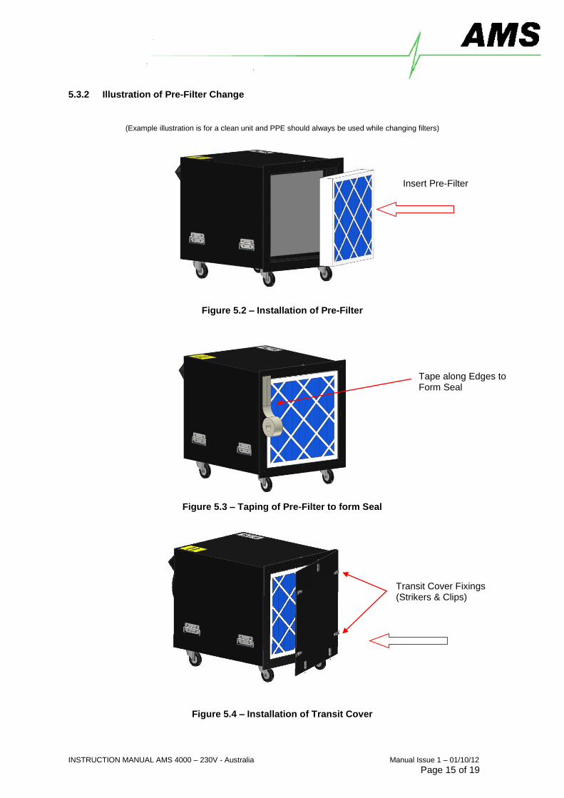
5.3.2 Illustration of Pre-Filter Change
(Example illustration is for a clean unit and PPE should always be used while changing filters)
Figure 5.2 – Installation of Pre-Filter
Figure 5.3 – Taping of Pre-Filter to form Seal
Figure 5.4 – Installation of Transit Cover
Transit Cover Fixings (Strikers & Clips)
Insert Pre-Filter
Tape along Edges to Form Seal
INSTRUCTION MANUAL AMS 4000 – 230V - Australia Manual Issue 1 – 01/10/12
Page 16 of 19
5.3.3 HEPA Filter Change Description
- Under no circumstances can the HEPA filter be changed whilst operational and in situ.
- All HEPA filter changes must be undertaken by qualified and competent service
engineers under fully controlled conditions.
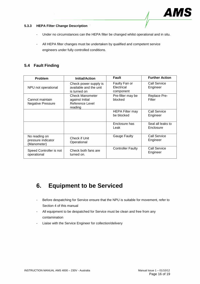
5.4 Fault Finding
Problem Initial/Action Fault Further Action
NPU not operational Check power supply is available and the unit is turned on
Faulty Fan or Electrical component
Call Service Engineer
Cannot maintain Negative Pressure
Check Manometer against Initial Reference Level reading
Pre-filter may be blocked
Replace Pre-Filter
HEPA Filter may be blocked
Call Service Engineer
Enclosure has Leak
Seal all leaks to Enclosure
No reading on pressure indicator (Manometer)
Check if Unit Operational
Gauge Faulty Call Service Engineer
Speed Controller is not operational
Check both fans are turned on.
Controller Faulty Call Service Engineer
6. Equipment to be Serviced
- Before despatching for Service ensure that the NPU is suitable for movement, refer to
Section 4 of this manual
- All equipment to be despatched for Service must be clean and free from any
contamination
- Liaise with the Service Engineer for collection/delivery
INSTRUCTION MANUAL AMS 4000 – 230V - Australia Manual Issue 1 – 01/10/12
Page 17 of 19
7. Accessories
7.1 Recommended Accessories
- Pre-filters to recommended standards.
- Flexible Ducting, either aluminium foil or PVC.
- Extension Pre-Filter box
7.2 Optional Extras In addition, the following optional extras can be supplied, these would have to be factory fitted at the
NPU’s next service or supplied when new.
- Hour Counter
o Allows the monitoring of a unit’s processing time and could be used to
determine when filter change is likely.
- Residual Current Device
o A safety device that cuts the power supply when an electrical short circuit
occurs within the system.
- Extension Pre-Filter Box
o An additional pre-filter box connected to the NPU by means of flexible
ductwork to allow the air intake of the unit to be located to suit site conditions.
- Alarm Socket
o Alarm that sounds when power supply to NPU fails. Backup batteries allow
alarm to function during power cut.
- Remote alarm Device
o An audible and visual alarm indicator to be connected to the Alarm socket
- Remote Device Power Outlet
o A power outlet to be used for other appliances or tools (to correct power
rating).
INSTRUCTION MANUAL AMS 4000 – 230V - Australia Manual Issue 1 – 01/10/12
Page 18 of 19
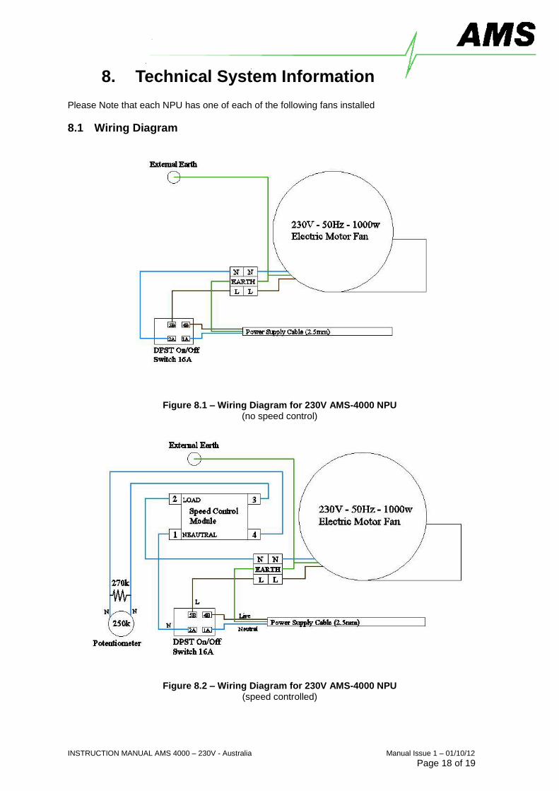
8. Technical System Information Please Note that each NPU has one of each of the following fans installed
8.1 Wiring Diagram
Figure 8.1 – Wiring Diagram for 230V AMS-4000 NPU (no speed control)
Figure 8.2 – Wiring Diagram for 230V AMS-4000 NPU
(speed controlled)

INSTRUCTION MANUAL AMS 4000 – 230V - Australia Manual Issue 1 – 01/10/12
Page 19 of 19
9. Test Reports
9.1 Airflow Tests
NPU1 NPU2 NPU3 NPU4 NPU5 Maximum Airflow
Serial No 12712 12711 12710 12709 12673 Performance (m3/h)
Manometer Reading 450 450 450 450 450
Skirt Area m
2 (A) 0.3564 0.3564 0.3564 0.3564 0.3564
Average Face Velocity m/s (Y) 4.2 4.122 3.877 4.144 3.788
Calculation:
A x 3600 x Y =
+ + + + + / 5 =
5388.8 5288.7 4974.3 5316.9 4860.2 5166
Total: 25828.88
Model Tested: AMS-4000 NPU One Piece
Anemometer Type:
Tested By: Ian Maarsden Engineer:
Air Management Systems Ltd
Unit One, 9 Cannon Lane Tonbridge, Kent, TN9 1PP Test Date: Engineer Signature:
14/10/2010