INSTRUCTION MANUAL - 2helpU · the instruction manual for recommended accessories. The use of...
28
DW745-XE HEAVY-DUTY 250 mm (10") COMPACT JOB SITE TABLE SAW INSTRUCTION MANUAL FINAL PRINT SIZE: 8.5 x 5.5"
Transcript of INSTRUCTION MANUAL - 2helpU · the instruction manual for recommended accessories. The use of...
DW745-XE
HEAVY-DUTY 250 mm (10") COMPACT JOB SITE TABLE SAW
INSTRUCTION MANUAL
FINAL PRINT SIZE: 8.5 x 5.5"

2
TABLE OF CONTENTSGeneral Safety Rules ................................................................................................ 1
Double Insulation ............................................................................................ 1
Electrical Safety .............................................................................................. 1
Important Safety Instructions ................................................................................... 1
Additional Safety Rules for Table Saws ..................................................................... 3
Specifications .......................................................................................................... 6
Unpacking ................................................................................................................ 6
Features ................................................................................................................... 6
Assembly ................................................................................................................. 7
Rip Fence........................................................................................................ 8
Anti-Kickback Assembly .................................................................................. 9
Blade Guard Assembly .................................................................................... 9
Miter Gauge .................................................................................................. 10
Bench Mounting ............................................................................................ 10
Connecting to Power Source ......................................................................... 11
On/Off Switch ............................................................................................... 11
Rip Fence Operation ...................................................................................... 11
Adjustments ........................................................................................................... 12
Rail Lock Adjustment .................................................................................... 12
Rip Scale Adjustment .................................................................................... 12
Blade Alignment Adjustment .......................................................................... 13
Fence Alignment Adjustment ......................................................................... 13
Bevel Stop and Pointer Adjustment ................................................................ 13
Bevel Lock Adjustment .................................................................................. 13
Miter Gauge Adjustment ................................................................................ 14
Aligning Riving Knife to Blade ........................................................................ 14
Saw Blades ................................................................................................... 15
Riving Knife Selection ................................................................................... 16
Kickback ....................................................................................................... 17
Operation ............................................................................................................... 17
Guard Operating Feature ................................................................................ 17
Ripping ......................................................................................................... 18
Narrow Rip Auxiliary Fence ........................................................................... 19
Push Block ................................................................................................... 19
Bevel Ripping ................................................................................................ 20
Crosscutting ................................................................................................. 20
Bevel Crosscutting ........................................................................................ 21
Mitering ........................................................................................................ 21
Miter Gauge Operation .................................................................................. 22
Compound Mitering....................................................................................... 22
Featherboard Construction ............................................................................ 22
Dust Collection.............................................................................................. 23
Lubrication .................................................................................................... 23
Storage ......................................................................................................... 23
Maintenance .......................................................................................................... 24
Cleaning........................................................................................................ 24
Repairs ......................................................................................................... 24
Accessories .................................................................................................. 24
Push Stick Pattern .................................................................................................. 25

1
Definitions: Safety Guidelines The definitions below describe the level of severity for each signal word. Please read the manual and pay attention to these symbols.
DANGER: Indicates an imminently hazardous situation which, if not avoided, will result in death or serious injury.
WARNING: Indicates a potentially hazardous situation which, if not avoided, could result in death or serious injury.
CAUTION: Indicates a potentially hazardous situation which, if not avoided, may result in minor or moderate injury.NOTICE: indicates a practice not related to personal injury which, if not avoided, may result in property damage.
IF YOU HAVE ANY QUESTIONS OR COMMENTS ABOUT THIS OR ANY DeWALT TOOL, CALL US AT: 1800 338 002 (Aust) or 0800 339 258 (NZ).
General Safety RulesWARNING: Read all instructions before operating product. Failure to follow all instructions listed below may result in electric shock, fire and/or serious injury.
SAVE ALL WARNINGS AND INSTRUCTIONS FOR FUTURE REFERENCE
Double InsulationIf saw is of double-insulated construction, read the following instructions.Double insulated tools are constructed throughout with two separate layers of electrical insulation or one double thickness of insulation between you and the tool’s electrical system. Tools built with this insulation system are not intended to be grounded.NOTE: Double insulation does not take the place of normal safety precautions when operating this tool. The insulation system is for added protection against injury resulting from a possible electrical insulation failure within the tool.
CAUTION: WHEN SERVICING USE ONLY IDENTICAL REPLACEMENT PARTS. Repair or replace damaged cords.
Electrical SafetyThe electric motor has been designed for one voltage only. Always check that the power supply corresponds to the voltage on the rating plate. 230 V AC means your tool will operate on alternating current. As little as 10% lower voltage can cause loss of power and can result in overheating. All DeWALT tools are factory tested; if this tool does not operate, check the power supply. Your DeWALT tool is double insulated, therefore no earth wire is required. • Young children and the infirm. This appliance is not intended for use by
young children or infirm persons without supervision. Young children should be supervised to ensure that they do not play with this appliance.
– This appliance is not intended for use by persons (including children) with reduced physical, sensory or mental capabilities, or lack of experience and knowledge, unless they have been given supervision or instruction concerning use of the appliance by a person responsible for their safety.
– Children should be supervised to ensure that they do not play with the appliance. • Replacement of the supply cord. If the supply cord is damaged, it must be
replaced by the manufacturer or an authorised DeWALT Service Centre in order to avoid a hazard.
Important Safety Instructions • TO REDUCE THE RISK OF KICKBACK AND OTHER INJURIES, use all
components of the guarding system (blade guard assembly, riving knife and anti-kickback) for every operation for which they can be used including all through cutting.
• REMOVE ADJUSTING KEYS AND WRENCHES. Form habit of checking to see that keys and adjusting wrenches are removed from spindle before turning tool on. Tools, scrap pieces, and other debris can be thrown at high speed, causing injury.
• KEEP WORK AREA CLEAN. Cluttered areas and benches invite accidents. • DO NOT USE THE MACHINE IN A DANGEROUS ENVIRONMENT. The use of
power tools in damp or wet locations or in rain can cause shock or electrocution. Keep your work area well-lit to avoid tripping or placing arms, hands, and fingers in danger.
• KEEP CHILDREN AWAY. All visitors should be kept at a safe distance from work area. Your shop is a potentially dangerous environment.

2
• MAKE WORKSHOP CHILDPROOF with padlocks, master switches, or by removing starter keys. The unauthorized start-up of a machine by a child or visitor may result in injury.
• DO NOT FORCE TOOL. It will do the job better and be safer at the rate for which it was designed.
• USE RIGHT TOOL. Don’t force tool or attachment to do a job for which it was not designed. Using the incorrect tool or attachment may result in personal injury.
• USE PROPER EXTENSION CORD. Make sure your extension cord is in good condition. If your product is equipped with a cordset, use only 3-wire extension cords that have 3-prong grounding-type plugs and 3-pole receptacles that accept the tool’s plug. When using an extension cord, be sure to use one heavy enough to carry the current your product will draw. An undersized cord will cause a drop in line voltage resulting in loss of power and overheating. The following table shows the correct size to use depending on cord length and nameplate ampere rating. If in doubt, use the next heavier gauge. The smaller the gauge number, the heavier the cord.
MINIMUM GAUGE FOR CORD SETSFor Cable length (m): 7.5 15 25 30 45 60Use Cable with minimum rating (Amperes)Tool Amperes 0 - 3.4 7.5 7.5 7.5 7.5 7.5 7.5 3.5 - 5.0 7.5 7.5 7.5 7.5 10 15 5.1 - 7.0 10 10 10 10 15 15 7.1 - 12.0 15 15 15 15 20 20 12.1 - 20.0 20 20 20 20 25 –
• WEAR PROPER APPAREL. No loose clothing, gloves, neckties, rings, bracelets, or other jewelry to get caught in moving parts. Non-slip footwear is recommended. Wear protective hair covering to contain long hair. Air vents may cover moving parts and should also be avoided.
• ALWAYS wear approved protective safety equipment complying with the following standards:
• Eye protection: AS/NZS1337 Eye Protectors for Industrial Applications;• Hearing protection: AS/NZS1270 Acoustics – Hearing Protection;• Respiratory protection: AS/NZS1716 Respiratory Protective Devices.
• DO NOT OVERREACH. Keep proper footing and balance at all times. Loss of balance may cause personal injury.
• MAINTAIN TOOLS WITH CARE. Keep blades sharp and clean for best and safest performance. Follow instructions for lubricating and changing accessories. Poorly maintained blades and machines can further damage the blade or machine and/or cause injury.
• TURN THE MACHINE “OFF”, AND DISCONNECT THE MACHINE FROM THE POWER SOURCE before installing or removing accessories, before adjusting or changing set-ups, when making repairs or changing locations. Do not touch the plug’s metal prongs when unplugging or plugging in the cord. An accidental start-up can cause injury.
• REDUCE THE RISK OF UNINTENTIONAL STARTING. Make sure that the switch is in the “OFF” position before plugging in the power cord. In the event of a power failure, move the switch to the “OFF” position. An accidental start-up can cause injury.
• USE RECOMMENDED ACCESSORIES. Use only accessories that are recommended by the manufacturer for your model. Accessories that may be suitable for one tool may be hazardous when used on another tool. Consult the instruction manual for recommended accessories. The use of improper accessories may cause risk of injury to persons.
• NEVER STAND ON TOOL. Serious injury could occur if the tool is tipped or if the cutting tool is unintentionally contacted.
• CHECK FOR DAMAGED PARTS. Before further use of the tool, a guard or other part that is damaged should be carefully checked to determine that it will operate properly and perform its intended function—check for alignment of moving parts, binding of moving parts, breakage of parts, mounting and any other conditions that may affect its operation. A guard or other part that is damaged should be properly repaired or replaced. Do not use tool if switch does not turn it on and off. Damaged parts can cause further damage to the machine and/or personal injury.
• DIRECTION OF FEED. Feed work into a blade or cutter against the direction of rotation of the blade or cutter only.
• NEVER LEAVE TOOL RUNNING UNATTENDED. TURN POWER OFF. Don’t leave tool until it comes to a complete stop. Serious injury can result.
3
• DO NOT OPERATE ELECTRIC TOOLS NEAR FLAMMABLE LIQUIDS OR IN GASEOUS OR EXPLOSIVE ATMOSPHERES. Motors and switches in these tools may spark and ignite fumes.
• STAY ALERT, WATCH WHAT YOU ARE DOING, AND USE COMMON SENSE. DO NOT USE THE MACHINE WHEN YOU ARE TIRED OR UNDER THE INFLUENCE OF DRUGS, ALCOHOL, OR MEDICATION. A moment of inattention while operating power tools may result in serious injury.
• DO NOT ALLOW FAMILIARITY (gained from frequent use of your saw) TO REPLACE SAFETY RULES. Always remember that a careless fraction of a second is sufficient to inflict severe injury.
Additional Safety Rules for Table SawsWARNING: ALWAYS USE SAFETY GLASSES. Everyday eyeglasses are NOT
safety glasses. Also use face or dust mask if cutting operation is dusty. All users and bystanders MUST ALWAYS wear certified safety equipment:
• Eye protection: AS/NZS1337 Eye Protectors for Industrial Applications;• Hearing protection: AS/NZS1270 Acoustics – Hearing Protection;• Respiratory protection: AS/NZS1716 Respiratory Protective Devices.
WARNING: Do not expose to rain or use in damp locations. • AVOID AWKWARD POSITIONS, where a sudden slip could cause a hand to move
into a saw blade. • NEVER REACH IN BACK OF, OR AROUND, THE CUTTING TOOL with either hand
to hold down the workpiece. • KEEP ARMS, HANDS AND FINGERS AWAY from the blade to prevent serious
injury. • USE A PUSH STICK THAT IS APPROPRIATE TO THE APPLICATION TO PUSH
WORKPIECES THROUGH THE SAW. A push stick is a wooden or plastic stick, usually homemade, that should be used whenever the size or shape of the workpiece would cause you to place your hands within 152 mm (6") of the blade.
• USE HOLD-DOWNS, JIGS, FIXTURES OR FEATHER BOARDS TO HELP GUIDE AND CONTROL THE WORKPIECE. Accessories for use with your tool are available at extra cost from your local dealer or authorized service center.
Instructions for making a push stick, a narrow rip auxiliary fence, a push block and feather boards are included in this manual.
• DO NOT PERFORM RIPPING, CROSSCUTTING OR ANY OTHER OPERATION FREEHAND.
• NEVER reach around or over saw blade. • STABILITY. Make sure the table saw is firmly mounted to a secure surface before
use and does not move. • NEVER CUT METALS, CEMENT BOARD OR MASONRY. Certain man-made
materials have special instructions for cutting on table saws. Follow the manufacturer’s recommendations at all times. Damage to the saw and personal injury may result.
• THE PROPER THROAT PLATE MUST BE LOCKED IN PLACE AT ALL TIMES to reduce the risk of a thrown workpiece and possible injury.
• USE THE CORRECT SAW BLADE FOR THE INTENDED OPERATION. The blade must rotate toward the front of the saw. Always tighten the blade arbor nut securely. Before use, inspect the blade for cracks or missing teeth. Do not use a damaged or dull blade.
• NEVER ATTEMPT TO FREE A STALLED SAW BLADE WITHOUT FIRST TURNING THE MACHINE OFF AND DISCONNECTING THE SAW FROM THE POWER SOURCE. If a workpiece or cut-off piece becomes trapped inside the blade guard assembly, turn saw off and wait for blade to stop before lifting the blade guard assembly and removing the piece.
• NEVER START THE MACHINE with the workpiece against the blade to reduce the risk of a thrown workpiece and personal injury.
• NEVER have any part of your body in line with the path of the saw blade. Personal injury may occur.
• NEVER PERFORM LAYOUT, ASSEMBLY OR SET-UP WORK on the table/work area when the machine is running. A sudden slip could cause a hand to move into the blade. Severe injury can result.
• CLEAN THE TABLE/WORK AREA BEFORE LEAVING THE MACHINE. Lock the switch in the “OFF” position and disconnect from the power source to prevent unauthorized use.
• DO NOT leave a long board (or other workpiece) unsupported so the spring of the board causes it to shift on the table resulting in loss of control and

4
• Freehand refers to cutting without the use of a miter gauge or rip fence or any other means of guiding or holding the workpiece other than the operator’s hand.
WARNING: Never perform freehand cutting with this saw. • Plunge cutting refers to blind cuts in the workpiece made by either raising the
blade through the workpiece or lowering the workpiece down to the blade. WARNING: Never perform plunge cutting with this saw. • Resawing – Flipping material to make a cut the saw is not capable of making in
one pass. WARNING: Resawing IS NOT recommended. SAW BLADE GUARD ASSEMBLY, ANTI-KICKBACK ASSEMBLY AND RIVING KNIFEYour table saw is equipped with a blade guard assembly, anti-kickback assembly and riving knife that covers the blade and reduces the possibility of accidental blade contact. The riving knife is a flat plate that fits into the cut made by the saw blade and effectively fights kickback by lessening the tendency of the blade to bind in the cut. The blade guard assembly and anti-kickback assembly can only be used when making through cuts that sever the wood. When making rabbets and other cuts that make non through cuts, the blade guard assembly and anti-kickback assembly must be removed and riving knife lowered to the non through cut position marked on the riving knife. Two anti-kickback pawls are located on the sides of the riving knife that allow the wood to pass through the blade in the cutting direction but reduce the possibility of the material being thrown backwards toward the operator.Use all components of the guarding system (blade guard assembly, riving knife and anti-kickback assembly) for every operation for which they can be used including all through cutting. If you elect not to use any of these components for a particular application exercise additional caution regarding control of the workpiece, the use of push sticks, the position of your hands relative to the blade, the use of safety glasses, the means to avoid kickback and all other warnings contained in this manual and on the saw itself. Replace the guarding systems as soon as you return to thru-cutting operations. Keep the guard assembly in working order.MAKING A PUSH STICK (Inside Back Cover) • In order to operate your table saw safely you must use a push stick whenever
the size or shape of the workpiece would cause your hands to be within 152 mm (6") of the saw blade or other cutter. A push stick is included with this saw.
• No special wood is needed to make additional push-sticks as long as it’s sturdy and long enough. A length of 400 mm (15.7") is recommended with a notch
possible injury. Provide proper support for the workpiece, based on its size and the type of operation to be performed. Hold the work firmly against the fence and down against the table surface.
• IF YOUR SAW makes an unfamiliar noise or if it vibrates excessively, cease operating immediately, turn unit off and disconnect from power source until the problem has been located and corrected. Contact a DeWALT factory service center, a DeWALT authorized service center or other qualified service personnel if the problem can not be found.
• KEEP OUT of the line of saw blade. Stand to the side whenever possible. • USE RECOMMENDED ACCESSORIES. The use of improper accessories may
cause risk of personal injury. • DO NOT OPERATE THIS MACHINE until it is completely assembled and installed
according to the instructions. A machine incorrectly assembled can cause serious injury.
• OBTAIN ADVICE from your supervisor, instructor, or another qualified person if you are not thoroughly familiar with the operation of this machine. Knowledge is safety.
• ADDITIONAL INFORMATION regarding the safe and proper operation of power tools (i.e. a safety video)is available from the Power Tool Institute, 1300 Sumner Avenue, Cleveland, OH 44115-2851 (www.powertoolinstitute.com). Information is also available from the National Safety Council, 1121 Spring Lake Drive, Itasca, IL 60143-3201. Please refer to the American National Standards Institute ANSI 01.1 Safety Requirements for Woodworking Machines and the U.S. Department of Labor OSHA 1910.213 Regulations.
TERMS: THE FOLLOWING TERMS WILL BE USED THROUGHOUT THE MANUAL AND YOU SHOULD BECOME FAMILIAR WITH THEM. • Thru sawing refers to any cut that completely cuts through the workpiece. • Non-thru sawing refers to any cut that does not completely cut through the
workpiece. • Push Stick refers to a wooden or plastic stick, usually homemade, that is used to
push small workpiece through the saw and keeps the operator’s hands clear of the blade.
• Kickback occurs when the saw blade binds in the cut and violently thrusts the workpiece back toward the operator.

5
that fits against the edge of the workpiece to prevent slipping. It’s a good idea to have several push sticks of the same length [400 mm (15.7")] with different size notches for different workpiece thicknesses.
• See the inside back cover for a picture of a push stick. The shape can vary to suit your own needs as long as it performs its intended function of keeping your hands away from the blade.
KICKBACKSKICKBACKS: Kickbacks can cause serious injury. A kickback occurs when a part of the workpiece binds between the saw blade and the rip fence, or other fixed object, and rises from the table and is thrown toward the operator. Kickbacks can be avoided by attention to the following conditions. How to Avoid Them and Protect Yourself from Possible Injury a. Be certain that the rip fence is parallel to the saw blade. b. Do not rip by applying the feed force to the section of the workpiece that will
become the cut-off (free) piece. Feed force when ripping should always be applied between the saw blade and the fence; use a push stick for narrow work, 152 mm (6") wide or less.
c. Keep saw blade guard assembly, riving knife and anti-kickback assembly in place and operating properly. If anti-kickback assembly is not operational, return your unit to the nearest authorized DeWALT service center for repair. The riving knife must be in alignment with the saw blade and the anti-kickback assembly must stop a kickback once it has started. Check their action before ripping by pushing the wood under the anti-kickback assembly. The teeth must prevent the wood from being pulled toward the front of the saw.
d. Plastic and composite (like hardboard) materials may be cut on your saw. However, since these are usually quite hard and slippery, the anti-kickback pawls may not stop a kickback. Therefore, be especially attentive to following proper set up and cutting procedures for ripping.
e. Use saw blade guard assembly, anti-kickback assembly and riving knife for every operation for which it can be used, including all through-sawing.
f. Push the workpiece past the saw blade prior to release.
g. NEVER rip a workpiece that is twisted or warped, or does not have a straight edge to guide along the fence.
h. NEVER saw a large workpiece that cannot be controlled. i. NEVER use the fence as a guide or length stop when crosscutting. j. NEVER saw a workpiece with loose knots, flaws, nails or other foreign objects. k. NEVER rip a workpiece shorter than 250 mm (10"). l. NEVER use a dull blade – replace or have resharpened.
WARNING: Some dust created by power sanding, sawing, grinding, drilling, and other construction activities contains chemicals known to cause cancer, birth defects or other reproductive harm. Some examples of these chemicals are:
• lead from lead-based paints,• crystalline silica from bricks and cement and other masonry products, and • arsenic and chromium from chemically-treated lumber.
Your risk from these exposures varies, depending on how often you do this type of work. To reduce your exposure to these chemicals: work in a well ventilated area, and work with approved safety equipment, such as those dust masks that are specially designed to filter out microscopic particles. • Avoid prolonged contact with dust from power sanding, sawing, grinding,
drilling, and other construction activities. Wear protective clothing and wash exposed areas with soap and water. Allowing dust to get into your mouth, eyes, or lay on the skin may promote absorption of harmful chemicals.
WARNING: Use of this tool can generate and/or disburse dust, which may cause serious and permanent respiratory or other injury. Always use AS/NZS standard approved respiratory protection appropriate for the dust exposure. Direct particles away from face and body.
WARNING: We recommend the use of a residual current device with a residual current rating of 30mA or less.
WARNING: Always wear proper personal hearing protection that conforms to AS/NZS1270 during use. Under some conditions and duration of use, noise from this product may contribute to hearing loss.

6
SAVE ALL WARNINGS AND INSTRUCTIONS FOR FUTURE REFERENCE
SpecificationsAmperes 7.9 A Miter Angle 60° L and RBevel Angle 0° to 45° LBlade Size 250 mm (10")Max. Cut Depth 0° Bevel 77 mm (3-1/8")Max. Cut Depth 45° Bevel 57 mm (2-1/4")RPM, no load 3800
Unpacking WARNING: To reduce the risk of injury, DO NOT connect the machine to the power
source until the table saw is completely assembled and you read the entire instruction manual.Open the box and slide the saw out, as FIG. 1 shown in Figure 1. Carefully unpack the table saw and all loose items from the carton. Examine all parts to make sure that parts have not been damaged during shipping. If any parts are missing or damaged, contact your dealer to replace them before attempting to assemble the tool.Refer to Figure 2 for the loose items and hardware included with the saw: 1. Rip fence 2. Arbor wrench and spindle wrench (attached to saw base)
3. Blade guard assembly 4. Miter gauge 5. Push stick (attached to rip fence)
WARNING: To reduce the risk of serious personal injury, have push stick ready to use before starting cut.
FIG. 2
FEATURES (Fig. 3, 4)Examine Figures 3 and 4 to become familiar with the saw and its various parts. The following sections on assembly and adjustments will refer to these terms and you must know what and where the parts are.

7
FIG. 3
A
B DE
F
G
H
I
N
JK
M
L
N
O
P
CQ
FIGURE 3 A. Table J. Bevel lock lever B. Miter gauge K. On/off switch C. Blade L. Rip fence indicator D. Blade guard assembly M. Adjustable feet E. Fence N. Mounting holes F. Fence rails O. Cord wrap G. Rip fence front latch P. Handle H. Fine adjustment knob Q. Anti-kickback assembly I. Blade height adjustment wheel
FIG. 4
W
S
R
D
T
V
U
FIGURE 4 R. Rip fence rear latch V. Arbor wrench, spindle wrench S. Dust collection port W. Rail lock lever T. Dust shroud U. Push stick
ASSEMBLYWARNING: Shock Hazard. To reduce the risk of serious personal injury, turn
unit off and disconnect machine from power source before attempting to move it, change accessories or make any adjustments.

8
TO REMOVE THE THROAT PLATE (FIG. 7A) 1. Remove the throat plate (X) by turning the cam lock knob (CC) 1/4 turn
counterclockwise 2. Using finger hole (XX) on the plate, pull throat plate up and forward to expose the
inside of the saw.
FIG. 7B
A1
ZZ
YY
FF
CC
XX
X
FIG. 7A
POSITIONING THE RIVING KNIFE (FIG. 7, 8) 1. Raise the saw blade arbor to its maximum height. 2. Loosen the riving knife lock knob (YY) (minimum of three turns). 3. To disengage riving knife lock pin, push lock knob toward the riving knife as
indicated by the yellow arrows on the knob. 4. Lift and slide the riving knife to the approximate position indicated by the
markings (non-thru and thru-position) on the riving knife and the lock pin will snap into place.
5. Tighten the riving knife lock knob.WARNING: Before connecting the table saw to the power source or operating the
saw, always inspect the blade guard assembly and riving knife for proper alignment and clearance with saw blade. Check alignment after each change of bevel angle.
ASSEMBLE YOUR SAW IN THE FOLLOWING ORDER 1. Rip fence (NOTE: Adjust rip scale before proceeding; refer to Rip Scale
Adjustment under Adjustment.) 2. Anti-kickback assembly 3. Blade guard assembly 4. Miter gauge (if required for application)NOTE: No tools needed for assembly. NOTE: Wrenches included with your saw are to remove and replace blades.
Rip Fence The rip fence can be installed on the left or right side of your table saw.TO ASSEMBLE THE RIP FENCE (FIG. 1, 5, 6) 1. Align the locator screw (AA) on the fence rail (F) with the fence head slot and
align the latch (G) with the opening (BB). 2. Secure the rip fence by snapping the latches onto the rails as shown in Figure 6.
Be sure to snap both front (G) and rear (R) latches in place.
FIG. 6
G
AA
BB
FIG. 5
AA
BB

9
NOTE: DO NOT operate saw if riving knife is not locked in the thru-cut (ZZ) or non thru-cut position (A1) hole.
YYFIG. 8A FIG. 8B FF
C
When properly aligned, the riving knife will be in line with the blade at both table top level, and at the top of the blade. Using a straight edge, ensure that the blade (C) is aligned with the riving knife (FF) as shown in Figure 8B. With power disconnected, operate the blade tilt and height adjustments through the extremes of travel and insure the blade guard assembly clears the blade in all operations and that the anti-kickback assembly is functioning. TO REPLACE THE THROAT PLATE 1. Align the throat plate as shown in Figure 7A, and insert the tabs on the back of
the throat plate into the holes on the back of the table opening. 2. Rotate cam counterclockwise until the front of throat plate drops into place.
Secure by rotating cam lock knob (CC) clockwise 1/4 turn (when cam lock is under the table holding the throat plate in place).
3. The throat plate includes four adjustment screws which raise or lower the throat plate. When properly adjusted, the front of the throat plate should be flush or slightly below the surface of the table top and secured in place. The rear of the throat plate should be flush or slightly above the table top.
WARNING: To reduce the risk of serious personal injury, the throat plate must be locked in place at all times.
Anti-Kickback Assembly (Fig. 9)WARNING: To reduce the risk of serious personal injury, the anti-kickback
assembly must be in place for all possible cuts. 1. Remove the anti-kickback assembly (Q) from the storage position. Refer to
Storage. 2. Locate the anti-kickback mounting hole and slot (EE) at the top of the riving knife (FF). 3. Slide the anti-kickback housing along the top of the riving knife until the stem (GG)
locates the slot above the mounting hole. Depress the stem (GG) on the anti-kickback assembly to allow the assembly to drop into the hole (EE). Push down on the anti-kickback assembly until it snaps into place and locks the assembly. NOTE: Pull up on the anti-kickback assembly to ensure it has locked into place.
GG
Q
FF
FIG. 9EE
Blade Guard Assembly (Fig. 10, 11)TO ATTACH BLADE GUARD ASSEMBLY
WARNING: To reduce the risk of serious personal injury, the blade guard assembly must be in place for all possible cuts. 1. While holding the blade guard assembly (D) in a vertical position slide the
locating pin (HH) into the riving knife slot (II) centering the riving knife within the v-shaped notch in the top guard. Refer to Figure 10.
2. Rotate the blade guard assembly towards the front of the saw while keeping the pin (HH) at the top of the riving knife slot. Rotate until the blade guard assembly is parallel to the table. Refer to Figure 11.
10
HH
D
FIG. 10
II
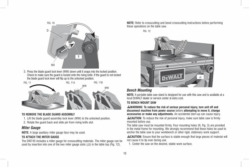
3. Press the blade guard lock lever (WW) down until it snaps into the locked position. Check to make sure the guard is locked onto the riving knife. If the guard is not locked the blade guard lock lever will flip up to the unlocked position.
WWFIG. 11 FIG. 11A FIG. 11B
WW
TO REMOVE THE BLADE GUARD ASSEMBLY 1. Lift the blade guard assembly lock lever (WW) to the unlocked position. 2. Rotate the guard back and slide pin from riving knife slot.
Miter GaugeNOTE: A large auxiliary miter gauge face may be used.TO ATTACH THE MITER GAUGEThe DW745 includes a miter gauge for crosscutting materials. The miter gauge can be used by insertion into one of the two miter gauge slots (JJ) in the table top (Fig. 12).
NOTE: Refer to crosscutting and bevel crosscutting instructions before performing these operations on the table saw.
FIG. 12
JJ
Bench MountingNOTE: A portable table saw stand is designed for use with this saw and is available at a local DeWALT dealer or service center at extra cost.TO BENCH MOUNT SAW
WARNING: To reduce the risk of serious personal injury, turn unit off and disconnect machine from power source before attempting to move it, change accessories or make any adjustments. An accidental start-up can cause injury.
CAUTION: To reduce the risk of personal injury, make sure table saw is firmly mounted before use.The table saw must be mounted firmly. Four mounting holes (N, Fig. 3) are provided in the metal frame for mounting. We strongly recommend that these holes be used to anchor the table saw to your workbench or other rigid, stationary work support.
CAUTION: Ensure that the surface is stable enough that large pieces of material will not cause it to tip over during use. 1. Center the saw on the desired, stable work surface.

11
2. Drive four 88.9 mm (3-1/2") long screws through the holes in the metal frame. Make sure the screws extend through the frame and securely attach to the supporting work surface.
If marring the supporting work surface is a concern, the DW745 can be mounted to scrap wood which can then be clamped onto the desired work surface. 1. Cut a piece of 88.9 mm (3/4") plywood to fit beneath the footprint of the saw. 2. Screw the saw to the plywood and clamp the overhang of the plywood to the
work surface. If the screws protrude through the plywood base, set it on two scrap pieces of material of equal thickness and attach them to the edges of the plywood to hold the saw further off of the work surface and prevent the screws from marring the surface.
Connecting Saw to Power SourceWARNING: To reduce the risk of injury, before connecting saw to power source,
make sure the switch is in the OFF position. Be sure your power supply agrees with the nameplate marking. 230 V AC Only means that your saw will operate on alternating current only. A voltage decrease of 10 percent or more will cause a loss of power and overheating. All DeWALT tools are factory tested. If this tool does not operate, check the power supply.
On/Off Switch FIG. 13
K
KK
WARNING: To reduce the risk of injury, be sure switch is in the OFF position before plugging machine in.Lift the on/off switch (K) paddle up to turn your saw ON and push it down to turn your saw OFF.A hole (KK) is provided in the switch for insertion of a padlock with a removable shank to lock the saw off (Fig. 13).NOTE: A conventional padlock will not fit.
Rip Fence Operation RAIL LOCK LEVER (FIG. 4)The rail lock lever (W) locks the fence in place preventing movement during cutting.
To lock the rail lever, push it down and toward the rear of the saw. To unlock, pull it up and toward the front of the saw. NOTE: When ripping, always lock the rail lock lever.WORK SUPPORT EXTENSIONYour table saw is equipped with a work support extension to support work that extends beyond the saw table. To use the work support extension, rotate it as shown in Figure 14. When not in use, the work support extension retracts, as shown in Figure 15. NOTE: Retract the work support extension whenever working over the table.
FIG. 14 FIG. 15
FINE ADJUSTMENT KNOB FIG. 16
NN
H
(FIG. 16)The fine adjustment knob (H) allows smaller adjustments when setting the fence. Before adjusting, be sure the rail lock lever is in its up or unlocked, position.

12
RIP SCALE POINTERThe rip scale pointer will need to be adjusted for proper performance of the rip fence if the user switches between thick and thin kerf blades. Refer to Rip Scale Adjustment under Adjustments for alignment instructions.
ADJUSTMENTSWARNING: To reduce the risk of injury, turn unit off and disconnect machine
from power source before installing and removing accessories, before adjusting or changing set-ups or when making repairs. An accidental start-up can cause injury. NOTE: Your saw is fully and accurately adjusted at the factory at the time of manufacture. If readjustment due to shipping and handling or any other reason is required, follow the steps below to adjust your saw. Once made, these adjustments should remain accurate. Take a little time now to follow these directions carefully to maintain the accuracy of which your saw is capable.
FIG. 17
LL
MM
FIG. 18
W
Rail Lock Adjustment (Tightening Fence Clamping System) 1. Lock the rail lock lever (W). 2. On the underside of the saw, loosen the nut (LL) (Fig. 17).
3. Tighten the hex rod (MM) until the spring on the locking system is compressed creating the desired tension on the rail lock lever. Retighten the jam nut against the hex rod.
4. Flip the saw over and check that the fence does not move when the lock lever is engaged. If the fence is still loose, tighten the spring further.
Rip Scale Adjustment (Calibrating Rip Scale) 1. Unlock the rail lock lever (W). 2. Set the blade at 0° bevel and move the fence until it is flush with the blade. 3. Lock the rail lock lever. 4. Loosen the screws (NN, Fig. 16) in the rip scale pointer with a crosshead
screwdriver and reset the red line to 0° on the scale. 5. Tighten the screws back into the rail. NOTE: The rip scale only reads correctly when the fence is mounted on the right side of the blade.
FIG. 19
OO

13
Blade Alignment Adjustment (Blade Parallel to Miter Slot)
WARNING: Cut Hazard. Check the blade at 0˚ and 45˚ to make sure blade does not hit the throat plate, causing personal injury.If the blade appears to be out of alignment with the miter slot on the table top, it will require calibration for alignment. To realign the blade and miter slot, use the following procedure: 1. Locate the black hex locator screws (OO) that hold up the trunnion to the
bottom of the table in the rear of the saw. 2. Loosen both screws and align the blade with the miter slot. Be sure to measure
between the miter slot and the back and front of the blade to ensure parallelism. 3. Snugly tighten the screws to secure the trunnion and blade assembly to the table
at the parallel position.
Fence Alignment Adjustment (Fig. 4, 5) (Blade Parallel to Fence) If you experience fence alignment problems and want to correct an out of parallel between the fence and the blade, be sure to check the alignment of the blade to the miter slot first. After confirming that those elements are aligned, proceed with alignment of the blade to the fence using the following procedure: 1. Unlock the rail lock lever (W) and locate the two fence locator screws (AA) that
support the fence on the front and rear rails. 2. Loosen the rear locator screw and adjust the position of the fence in the
groove on the fence until it sets the fence face parallel to the blade. Make sure you measure from the fence face to the front and back of the blade to ensure alignment.
3. Tighten the locator screw and repeat on the left side of the blade. 4. Check rip scale adjustment.
Bevel Stop and Pointer Adjustment (Calibrating Bevel Scale)Calibrating the bevel system on the saw may require two separate steps, one for the bevel scale and another for the bevel pointer. The scale should always be checked first followed by adjustments to the red pointer.
Bevel Lock Adjustment (Fig. 20)The bevel lock lever (J) may need adjustment to maintain lock force. To do this, put the lock lever in the locked position. Use a crosshead screwdriver to remove the screw (PP) holding the lock lever in place (Fig. 20). Remove the lock lever from the locking bolt and place lock lever in the desired position. Insert the screw (PP) and tighten securely.
FIG. 20
J
J
PP
PART A – ADJUSTING THE BEVEL SCALE SYSTEM (FIG. 21, 22) 1. Remove the Blade guard assembly from the saw and raise the blade all the way
up in the table. 2. Unlock the bevel lock lever (J) and loosen the bevel stop screw (QQ). 3. Place a square against the table and blade. NOTE: Be sure to place the square between the teeth on the blade to ensure an
accurate measurement. 4. Adjust the bevel angle until the blade is flat against the square. Lock the bevel
lock lever (J). 5. Move the bevel stop cam (RR) until it firmly contacts the trunnion casting.
Tighten the bevel stop screw. 6. Repeat procedure at 45˚ using a triangle or speed square.

14
FIG. 22FIG. 21 QQ SSRR
J
PART B – ADJUSTING THE BEVEL SCALE POINTERNOTE: Complete this step only if Part A has been completed. 7. Check the bevel scale angle. If the pointer does not read 0°, loosen the pointer
screw (SS) and move it to the 0° mark on the bevel scale. Retighten the pointer screw.
Miter Gauge Adjustment FIG. 23
TT
(Calibrating Miter Gauge Pointer)Your miter gauge features adjustable stops at 90° and 45° left and right. To adjust the miter gauge, loosen the screw (TT) and move to desired position. Tighten the screw against the stop plate (Fig. 23).
Aligning Riving Knife To Blade (Fig. 24) 1. Remove the throat plate. Refer
to To Remove Throat Plate under Assembly.
2. Raise the blade to full depth of cut and 0° bevel angle.
3. If needed, raise the riving FIG. 24
A1
ZZ
A2
A3
YY
FF
knife (FF) to the thru - cut (ZZ) or highest position. Refer to Positioning Riving Knife under Assembly.
4. Locate the three small set screws (A2) adjacent to the riving knife lock knob (YY). These screws will be used to adjust the riving knife position.
5. Lay a straight edge on the table against two blade tips. The riving knife should not touch the straight edge. If needed, loosen the two larger lock screws (A3).
6. Adjust the small set screws (A2) to move the riving knife according to the position noted in step 5. Lay the straight edge on the opposite side of the blade and repeat adjustments as needed.
7. Lightly tighten the two larger lock screws (A3). 8. Place a square flat against the riving knife to the verify riving knife is vertical and
in-line with the blade. 9. If needed, use the set screws to bring the riving knife vertical with the square. 10. Repeat steps 5 and 6 to verify position of riving knife. 11. Fully tighten the two larger lock screws (A3).
15
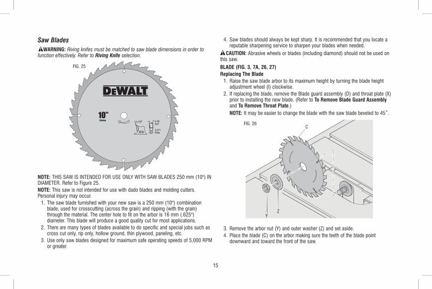
Saw Blades WARNING: Riving knifes must be matched to saw blade dimensions in order to
function effectively. Refer to Riving Knife selection.
FIG. 25
NOTE: THIS SAW IS INTENDED FOR USE ONLY WITH SAW BLADES 250 mm (10") IN DIAMETER. Refer to Figure 25.NOTE: This saw is not intended for use with dado blades and molding cutters. Personal injury may occur. 1. The saw blade furnished with your new saw is a 250 mm (10") combination
blade, used for crosscutting (across the grain) and ripping (with the grain) through the material. The center hole to fit on the arbor is 16 mm (.625") diameter. This blade will produce a good quality cut for most applications.
2. There are many types of blades available to do specific and special jobs such as cross cut only, rip only, hollow ground, thin plywood, paneling, etc.
3. Use only saw blades designed for maximum safe operating speeds of 5,000 RPM or greater.
4. Saw blades should always be kept sharp. It is recommended that you locate a reputable sharpening service to sharpen your blades when needed.
CAUTION: Abrasive wheels or blades (including diamond) should not be used on this saw.
BLADE (FIG. 3, 7A, 26, 27)Replacing The Blade 1. Raise the saw blade arbor to its maximum height by turning the blade height
adjustment wheel (I) clockwise. 2. If replacing the blade, remove the Blade guard assembly (D) and throat plate (X)
prior to installing the new blade. (Refer to To Remove Blade Guard Assembly and To Remove Throat Plate.)
NOTE: It may be easier to change the blade with the saw blade beveled to 45˚.
FIG. 26 C
ZY
3. Remove the arbor nut (Y) and outer washer (Z) and set aside. 4. Place the blade (C) on the arbor making sure the teeth of the blade point
downward and toward the front of the saw.

16
5. Place the outer washer (Z) against FIG. 27
Y
the blade, raised side out and tighten the arbor nut against the washer as far as possible by hand. Ensure that the outer washer and arbor nut are free of dust and debris before installing.
6. To further tighten the arbor nut (Y), use the open ended spindle wrench (supplied) to keep the spindle from rotating (Fig 26).
7. Use the arbor wrench (supplied) to hold the nut and tighten it by turning it clockwise. Reposition the wrench on the arbor nut and repeat as necessary until the nut and washer are securely fastened against the blade (Fig. 27).
NOTE: Different types of blades make different kerfs (width of cuts). Therefore, it is necessary to check adjustment of rip scale when changing blades. Replacement blade MUST not exceed the thickness stated on the riving knife. The riving knife provided with the saw is 2.2 mm (0.087") thick.
Riving Knife SelectionWARNING: To minimize the risk of kickback and to insure proper cutting, the riving
knife must be the proper thickness for the blade used.The riving knife supplied with this table saw is the correct size for the blade supplied with the saw. If a different blade is used, check the blade body, or plate, thickness and the blade kerf, or cutting, width marked on the blade or on the blade packaging. The riving knife thickness must be greater than the body thickness and less than the kerf width as shown in Figure 28. If it is not, the riving knife MUST be replaced with one that has the correct thickness.The riving knife provided with this saw is marked as follows (Fig. 29):
2.2 mm (0.087") THICK RIVING KNIFE. ONLY USE FOR 250 mm (10") Ø BLADE WITH 2.4 mm (0.094") MIN. KERF WIDTH AND 1.75 mm (0.067") MAX. BODY THICKNESS.
The riving knife available as an accessories marketed by DeWALT is marked as follows:
2.8 mm (0.110") THICK RIVING KNIFE. ONLY USE FOR 250 mm (10") Ø BLADE WITH 3.0 mm MIN. KERF WIDTH AND 2.5 mm (0.098") MAX. BODY THICKNESS
FIG. 29RIVING KNIFE THICKNESS
KERF WIDTH (WIDTH OF
CUT MADE BY THE BLADE)
BODY (OR PLATE)
THICKNESS OF THE BLADE
FIG. 28
All DeWALT blade body thickness and kerf FIG. 30 widths are provided on the website.If a different blade is used and the body thickness and kerf width dimensions are not provided, use the following procedure to determine the correct riving knife thickness: 1. Measure the body thickness of the blade. 2. Make a shallow cut in scrap material and
measure the kerf width. 3. Select the riving knife as shown in
Figure 28.

17
4. Slide the riving knife through the shallow cut made in step 2 to confirm the correct riving knife has been selected. The riving knife should not bind or drag through the cut.
IMPORTANT: If any dragging or binding of the material is encountered as it reaches the riving knife, turn unit off and disconnect machine from power source. Repeat steps 1–4 to make the proper riving knife selection before attempting another cut.
KickbackKickback is a dangerous condition! It is caused by the workpiece binding against the blade. The result is that the workpiece can move rapidly in a direction opposite to the feed direction. During kickback, the workpiece could be thrown back at the operator. It can also drag the operator’s hand back into the blade if the operator’s hand is at the rear of the blade. If kickback occurs, turn the saw OFF and verify the proper functioning of the riving knife, anti-kickback assembly and blade guard assembly before resuming work.
WARNING: Refer to Additional Safety Rules for Table Saws and follow all warnings provided regarding KICKBACK.
OPERATIONWARNING: Before using the saw, verify the following each and every time:
1. ALWAYS wear proper eye, hearing and respiratory equipment. 2. Blade is tight. 3. Bevel angle and height lock knobs are tight. 4. If ripping, ensure fence lock lever is tight and fence is parallel to the blade. 5. If crosscutting, miter gauge knob is tight. 6. The blade guard assembly is properly attached and the anti-kickback assembly is
functioning. 7. ALWAYS inspect the blade guard assembly and riving knife for proper alignment,
operation and clearance with saw blade. 8. ALWAYS make sure both guards are in the down position in contact with the table
before operating.Failure to adhere to these common safety rules can greatly increase the likelihood of injury.
WARNING: To reduce the risk of injury, turn unit off and disconnect machine from power source before installing and removing accessories, before adjusting or changing set-ups or when making repairs. An accidental start-up can cause injury.
WARNING: Before connecting the table saw to the power source or operating the saw, always inspect the blade guard assembly and riving knife for proper operation alignment and clearance with saw blade. Personal injury may result.
WARNING: Ripping or crosscutting may cause saw to tip over while operating. Make sure saw is securely mounted to a stable surface.
WARNING: Never use the fence and miter gauge together. This may cause a kickback condition and injure the operator.
CAUTION: If your saw makes an unfamiliar noise or if it vibrates excessively, cease operating immediately, turn unit off and disconnect from power source until the problem has been located and corrected. Contact a DeWALT factory service center, a DeWALT authorized service center or other qualified service personnel if the problem can not be found.
CAUTION: The proper throat plate must be in place at all times to reduce the risk of a thrown workpiece and possible injury. There are two basic types of cutting with table saws: ripping and crosscutting. Cutting with the grain is ripping and cutting against the grain is crosscutting. With manmade materials, the distinction is made such that ripping is cutting to a different width and crosscutting describes cutting material across the shorter dimension.
WARNING: When ripping, always use the fence to provide a guide for the material and blade guard assembly against a kickback situation.
WARNING: Never perform any cutting operation free hand. Never perform plunge cutting.
CAUTION: When crosscutting, always use the miter gauge.
Guard Operating Feature (Fig. 31)WARNING: To reduce the risk of injury, turn unit off and disconnect machine
from power source before installing and removing accessories, before adjusting or changing set-ups or when making repairs. An accidental start-up can cause injury. 1. The guard(s) will lock in place when in the raised position.

18
2. This feature increases visability when measuring the blade to fence distance. 3. Push down on guard(s) and they will release to the operating position. • ALWAYS make sure both guards are in the down position in contact with the
table before operating.
FIG. 31
RAISED POSITION
OPERATING POSITION
RippingWARNING: Never touch the “free end” of the workpiece or a “free piece” that is
cut off, while the power is ON and/or the saw blade is rotating. Piece may contact the blade resulting in a thrown workpiece and possible injury.
WARNING: A rip fence should ALWAYS be used for ripping operations to prevent loss of control and personal injury. NEVER perform a ripping operation freehand. ALWAYS lock the fence to the rail.
WARNING: When bevel ripping and whenever possible, place the fence on the side of the blade so that the blade is tilted away from the fence and hands. Keep hands clear of the blade and use a push stick to feed the workpiece if there is less than 152 mm (6") between the fence and the blade. 1. Lock the rip fence by pressing the rail lock lever down. Remove the miter gauge. 2. Raise the blade so it is about 3.2 mm (1/8") higher than the top of the workpiece. 3. Hold the workpiece flat on the table and against the fence. Keep the workpiece
about 25.4 mm (1") away from the blade.
CAUTION: The workpiece must have a straight edge against the fence and must not be warped, twisted or bowed. Keep both hands away from the blade and away from the path of the blade. Refer to proper hand position in Figure 32.
FIG. 32
4. Turn the saw on and allow the blade to come up to speed. Both hands can be used in starting the cut. When there is approximately 305 mm (12") left to be ripped, use only one hand, with your thumb pushing the material, your index and second finger holding the material down and your other fingers hooked over the fence. Always keep your thumb along side your first two fingers and near the fence.
5. Keeping the workpiece against the table and fence, slowly feed the workpiece rearward all the way through the saw blade. Continue pushing the workpiece until it is clear of the blade guard assembly and it falls off the rear of the table. Do not overload the motor.
6. Never try to pull the workpiece back with the blade turning. Turn the switch off, allow the blade to stop, raise the anti-kickback teeth on each side of the riving knife if necessary and slide the workpiece out.
7. When sawing a long piece of material or a panel, always use a work support. A sawhorse, rollers, or out feed assembly provides adequate support for this purpose. The work support must be at the same height as the saw table.
CAUTION: Never push or hold onto the “free” or “cut off” side of the workpiece.

19
FIG. 33
U
RIPPING SMALL PIECESIt is unsafe to rip small pieces. It is not safe to put your hands close to the blade. Instead, rip a larger piece to obtain the desired piece. When a small width is to be ripped and the hand cannot be safely put between the blade and the rip fence, use one or more push sticks. A pattern is included at the end of this manual to make push sticks. A push stick (U) is included with this saw, attached to the rip fence. Use the push stick(s) to hold the workpiece against the table and fence, and push the workpiece fully past the blade. Refer to Figure 33.
Narrow Rip Auxiliary Fence (Fig. 34, 36)The narrow rip auxiliary fence should be used for a rip measuring 50.8 mm (2") or narrower. This fence will allow the guard to remain on the saw when completing narrow ripping. This fence will provide ample space for proper use of a push block (A12, Refer to Push Block). 1. Follow the diagram in Figure 34 to construct the narrow rip auxiliary fence (A13).
NOTE: A11 should be cut to fit the length of the saw table top and sides (A14) must be parallel.
2. After the narrow rip auxiliary fence is constructed, slip it over the saw table top and place it flush to the fence as shown in Figure 36.
3. Feed the workpiece through until the edge of the material reaches the front edge of the saw table top.
9.5 mm (3/8")
25 mm (1")
12.7 mm (1/2")
FIG. 34
A14
A11
121 mm (4-3/4" )
9.5 mm (3/8")
4. Continue feeding the material using the push block (A12) until the cut is complete.
Push Block (Fig. 35, 36)IMPORTANT: Only use the push block (A12) with the narrow rip auxiliary fence, Refer to Narrow Rip Auxiliary Fence. The push block should be used once the material being cut reaches the saw table top. 1. Construct a push block using the diagram in Figure 35. NOTE: Edges (A15) must be the same size. IMPORTANT: The over hanging edge (A16, Fig. 35) MUST be square. An uneven
lip could cause the push block to slip or push the material away from the fence. 2. Place the push block (A12, Fig. 36) behind the material and ensure the lip of the
block is flush to the narrow rip auxiliary fence (A13).

20
305 mm (12")
A12
A15
FIG. 35
A1664 mm (2-1/2")
127 mm (5")
12.7 mm (1/2")
121 mm (4-3/4" )
305 mm (12")
12.7 mm (1/2")
133 mm (5-1/4")
64 mm (2-1/2")
12.7 mm (1/2")
FIG. 36A12
A13
3. Once the push block is in place, continue feeding the material until the cut is complete making sure the push block remains flush to the narrow rip auxiliary fence at all times.
IMPORTANT: The narrow rip auxiliary fence and the over hanging edge (A16, Fig. 35) should both be the same thickness.
Bevel RippingThis operation is the same as ripping except the bevel angle is set to an angle other than zero degrees.
WARNING: Before connecting the table saw to the power source or operating the saw, always inspect the blade guard assembly and riving knife for proper alignment and clearance with saw blade. Check alignment after each change of bevel angle.
CrosscuttingWARNING: NEVER touch the “free end” of the workpiece or a “free piece” that is
cut off, while the power is ON and/or the saw blade is rotating. Piece may contact the blade resulting in a thrown workpiece and possible injury.
WARNING: To reduce the risk of injury, NEVER use the fence as a guide or length stop when crosscutting.
WARNING: NEVER use a length stop on the free end of the workpiece when crosscutting. In short, the cut-off piece in any through-sawing (cutting completely through the workpiece) operation must never be confined — it must be allowed to move away from saw blade to prevent contact with blade resulting in a thrown workpiece and possibly injury.
WARNING: Use caution when starting the cut to prevent binding of the guard against the workpiece resulting in damage to saw and possible injury.
CAUTION: When using a block as a cut-off gauge, the block must be at least 19 mm (3/4") thick and is very important that the rear end of the block be positioned so the workpiece is clear of the block before it enters the blade to prevent contact with blade resulting in a thrown workpiece and possibly injury. 1. Remove the rip fence and place the miter gauge in the desired slot. 2. Adjust the blade height so that the blade is about 3.2 mm (1/8") higher than the
top of the workpiece.

21
3. Hold the workpiece firmly against the miter gauge with the path of the blade in line with the desired cut location. Keep the workpiece an inch or so in front of the blade. KEEP BOTH HANDS AWAY FROM THE BLADE AND THE PATH OF THE BLADE (Fig. 37).
FIG. 37
4. Start the saw motor and allow the blade to come up to speed. 5. While using both hands to keep the workpiece against the face of the miter
gauge, and holding the workpiece flat against the table, slowly push the workpiece through the blade. Refer to Figure 37.
6. Never try to pull the workpiece with the blade turning. Turn the switch off, allow the blade to stop, and carefully slide the workpiece out.
CAUTION: Never touch or hold onto the “free” or “cut off” end of the workpiece.
Bevel Crosscutting This operation is the same as crosscutting except that the bevel angle is set to an angle other than 0°. For proper hand position, refer to Figure 38.
WARNING: Before connecting the table saw to the power source or operating the saw, always inspect the blade guard assembly and riving knife for proper alignment and clearance with saw blade. Check alignment after each change of bevel angle.
FIG. 38
FIG. 39
MiteringWARNING: Miter angles greater than 45˚ may force the blade guard assembly
into the saw blade causing damage to the blade guard assembly and personal injury. Before starting the motor, test the operation by feeding the workpiece into the blade guard assembly. If the blade guard assembly contacts the blade, place the workpiece under the blade guard assembly, not touching the blade, before starting the motor.

22
CAUTION: Certain workpiece shapes, such as molding may not lift the blade guard assembly properly. Feed the workpiece slowly to start the cut. If the blade guard assembly contacts the blade, place the workpiece under the blade guard assembly, not touching the blade, before starting the motor.This operation is the same as crosscutting except the miter gauge is locked at an angle other than 0°. Hold the workpiece FIRMLY against the miter gauge and feed the workpiece slowly into the blade (to prevent the workpiece from moving). Refer to Figure 39.
FIG. 39
Miter Gauge OperationTo set your miter gauge, loosen the lock handle and move the miter gauge to the desired angle.
Compound MiteringThis is a combination of bevel crosscutting and mitering. Follow the instructions for both bevel crosscutting and mitering.
Featherboard ConstructionFeatherboards are used to keep the work in contact with the fence and table, and help prevent kickbacks. Dimensions for making a typical featherboard are shown in Fig. 40. Make the featherboard from a straight piece of wood that is free of knots
and cracks. Clamp the featherboard to the fence and table so that the leading edge of the featherboard will support the workpiece until the cut is complete (Fig. 41). An 203 mm (8") high flat board can be clamped to the rip fence and the featherboard can be clamped to the 203 mm (8") high board.
60º
FIG. 40610 mm (24")
127 mm (5")
20 mm (3/4") THE KERF
SHOULD BE ABOUT 6.4 mm (1/4") APART
102 mm (4")
WARNING: Use featherboards for all non-thru-sawing operations where the blade guard assembly, anti-kickback assembly and riving knife cannot be used. Always replace the blade guard assembly, anti-kickback assembly and riving knife when the non-thru-sawing operation is complete. Make sure the featherboard presses only on the portion of the workpiece in front of the blade.
FIG. 41
23
FIG. 42
VVUU
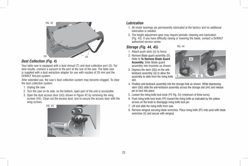
Dust Collection (Fig. 4)Your table saw is equipped with a dust shroud (T) and dust collection port (S). For best results, connect a vacuum to the port at the rear of the saw. The table saw is supplied with a dust extraction adapter for use with nozzles of 35 mm and the DeWALT AirLock system.After extended use, the saw’s dust collection system may become clogged. To clear the dust collection system: 1. Unplug the saw. 2. Turn the saw on its side, so the bottom, open part of the unit is accessible. 3. Open the dust access door (UU) shown in Figure 42 by removing the wing
screws (VV). Clean out the excess dust, and re-secure the access door with the wing screws.
FIG. 43
Lubrication 1. All motor bearings are permanently lubricated at the factory and no additional
lubrication is needed. 2. The height adjustment gear may require periodic cleaning and lubrication
(Fig. 43). If you have difficulty raising or lowering the blade, contact a DeWALT authorized service center.
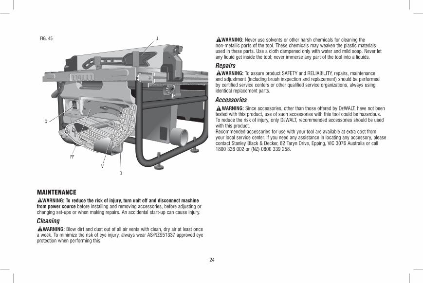
Storage (Fig. 44, 45)
A4
FIG. 44
Q GG
1. Attach push stick (U) to fence. 2. Remove Blade guard assembly (D).
Refer to To Remove Blade Guard Assembly. Slide Blade guard assembly into brackets as shown.
3. Depress the stem (GG) on the anti- kickback assembly (Q) to allow the assembly to slide from the riving knife slot.
4. Position anti-kickback assembly into the storage hole as shown. While depressing stem (GG) slide the anti-kickback assembly across the storage slot (A4) and release pin to lock into place.
5. Loosen the riving knife lock knob (YY, Fig. 24) (minimum of three turns). 6. Push riving knife lock knob (YY) toward the riving knife as indicated by the yellow
arrows on the knob to disengage riving knife lock pin. 7. Lift and slide the riving knife from saw. 8. Remove wingnut securing blade wrenches. Place riving knife (FF) onto post with blade
wrenches (V) and secure with wingnut.
24
FIG. 45 U
V
FF
Q
D
MAINTENANCEWARNING: To reduce the risk of injury, turn unit off and disconnect machine
from power source before installing and removing accessories, before adjusting or changing set-ups or when making repairs. An accidental start-up can cause injury.
CleaningWARNING: Blow dirt and dust out of all air vents with clean, dry air at least once
a week. To minimize the risk of eye injury, always wear AS/NZS51337 approved eye protection when performing this.
WARNING: Never use solvents or other harsh chemicals for cleaning the non-metallic parts of the tool. These chemicals may weaken the plastic materials used in these parts. Use a cloth dampened only with water and mild soap. Never let any liquid get inside the tool; never immerse any part of the tool into a liquids.
RepairsWARNING: To assure product SAFETY and RELIABILITY, repairs, maintenance
and adjustment (including brush inspection and replacement) should be performed by certified service centers or other qualified service organizations, always using identical replacement parts.
AccessoriesWARNING: Since accessories, other than those offered by DeWALT, have not been
tested with this product, use of such accessories with this tool could be hazardous. To reduce the risk of injury, only DeWALT, recommended accessories should be used with this product. Recommended accessories for use with your tool are available at extra cost from your local service center. If you need any assistance in locating any accessory, please contact Stanley Black & Decker, 82 Taryn Drive, Epping, VIC 3076 Australia or call 1800 338 002 or (NZ) 0800 339 258.

25
PUSH STICK PATTERNAdjust length of push stick so hand will clear blade guard and rip fence.
CAUTION: Make push stick from plywood or softwood equal to or less than the width of the material to be cut.
Notch to help prevent hand from slipping.
Cut off here to push 6.3 mm (1/4") wood.
Optional hanging hole.
Cut off here to push 12.7 mm (1/2") wood.

Stanley Black & Decker82 Taryn Drive, Epping, VIC 3076 Australia • 1800 338 002 (Aust) or 0800 339 258 (NZ)
www.dewalt.com.au • www.dewalt.co.nz
(AUG16) Part No. N481641 DW745-XE Copyright © 2008, 2014, 2016 DeWALT
The following are trademarks for one or more DeWALT power tools: the yellow and black color scheme; the “D” shaped air intake grill; the array of pyramids on the handgrip; the kit box configuration; and the array of lozenge-shaped humps on the surface of the tool.