Instruction Lock Mortiser and manual Lock Face … Mortiser and Lock Face Templet Instruction manual...
17
Part No. 904667 - 01-24-05 The Model and Serial No. plate is located on the main housing of the tool. Record these numbers in the spaces below and retain for future reference. Model No. ______________________________________ Type ___________________________________________ Serial No. _______________________________________ IMPORTANT Please make certain that the person who is to use this equipment carefully reads and understands these instructions before starting operations. To learn more about Porter-Cable visit our website at: http://www.porter-cable.com Copyright © 2005 Porter-Cable Corporation Lock Mortiser and Lock Face Templet Instruction manual ESPAÑOL: PÁGINA 17 FRANÇAISE : PAGE 35 MODEL 513 Mortiser MODEL 517 Lock Face Templet
Transcript of Instruction Lock Mortiser and manual Lock Face … Mortiser and Lock Face Templet Instruction manual...

Part No. 904667 - 01-24-05
The Model and Serial No. plate is located on the mainhousing of the tool. Record these numbers in thespaces below and retain for future reference.
Model No. ______________________________________
Type ___________________________________________
Serial No. _______________________________________
IMPORTANTPlease make certain that the person who isto use this equipment carefully reads andunderstands these instructions beforestarting operations.
To learn more about Porter-Cable visit our website at:
http://www.porter-cable.com
Copyright © 2005 Porter-Cable Corporation
Lock Mortiser andLock Face Templet
Instructionmanual
ESPAÑOL: PÁGINA 17FRANÇAISE : PAGE 35
MODEL 513 Mortiser
MODEL 517 Lock Face Templet

2
Read and understand all warnings and operating instructionsbefore using any tool or equipment. When using tools or equipment, basicsafety precautions should always be followed to reduce the risk of personalinjury. Improper operation, maintenance or modification of tools or equipmentcould result in serious injury and property damage. There are certainapplications for which tools and equipment are designed. Porter-Cable stronglyrecommends that this product NOT be modified and/or used for any applicationother than for which it was designed.
If you have any questions relative to its application DO NOT use the productuntil you have written Porter-Cable and we have advised you.
Online contact form at www.porter-cable.comPostal Mail: Technical Service Manager
Porter-Cable Corporation4825 Highway 45 NorthJackson, TN 38305
Information regarding the safe and proper operation of this tool is available fromthe following sources:Power Tool Institute1300 Sumner Avenue, Cleveland, OH 44115-2851www.powertoolinstitute.org
National Safety Council1121 Spring Lake Drive, Itasca, IL 60143-3201
American National Standards Institute, 25 West 43rd Street, 4 floor, New York,NY 10036 www.ansi.org ANSI 01.1Safety Requirements for WoodworkingMachines, and the U.S. Department of Labor regulations www.osha.gov
SAVE THESE INSTRUCTIONS!
IMPORTANT SAFETY INSTRUCTIONS . . . . . . . . . . . . . . . . . . . . . . . . . .2SAFETY GUIDELINES . . . . . . . . . . . . . . . . . . . . . . . . . . . . . . . . . . . . . . . .3GENERAL SAFETY RULES . . . . . . . . . . . . . . . . . . . . . . . . . . . . . . . . . . .4ADDITIONAL SPECIFIC SAFETY RULES . . . . . . . . . . . . . . . . . . . . . . . .6CARTON CONTENTS . . . . . . . . . . . . . . . . . . . . . . . . . . . . . . . . . . . . . . . .8FUNCTIONAL DESCRIPTION . . . . . . . . . . . . . . . . . . . . . . . . . . . . . . . . .8ASSEMBLY . . . . . . . . . . . . . . . . . . . . . . . . . . . . . . . . . . . . . . . . . . . . . . . .8OPERATION . . . . . . . . . . . . . . . . . . . . . . . . . . . . . . . . . . . . . . . . . . . . . . .9TROUBLESHOOTING . . . . . . . . . . . . . . . . . . . . . . . . . . . . . . . . . . . . . .15MAINTENANCE . . . . . . . . . . . . . . . . . . . . . . . . . . . . . . . . . . . . . . . . . . . .15SERVICE . . . . . . . . . . . . . . . . . . . . . . . . . . . . . . . . . . . . . . . . . . . . . . . . .16ACCESSORIES . . . . . . . . . . . . . . . . . . . . . . . . . . . . . . . . . . . . . . . . . . . .16WARRANTY . . . . . . . . . . . . . . . . . . . . . . . . . . . . . . . . . . . . . . . . . . . . . . .16ESPAÑOL . . . . . . . . . . . . . . . . . . . . . . . . . . . . . . . . . . . . . . . . . . . . . . . .17FRANÇAISE . . . . . . . . . . . . . . . . . . . . . . . . . . . . . . . . . . . . . . . . . . . . . .35SERVICE CENTER LOCATIONS . . . . . . . . . . . . . . . . . . . . . . .back cover
TABLE OF CONTENTS
IMPORTANT SAFETY INSTRUCTIONS

3
Some dust created by power sanding, sawing, grinding, drilling,and other construction activities contains chemicals known (to the
State of California) to cause cancer, birth defects or other reproductive harm. Someexamples of these chemicals are:● lead from lead-based paints● crystalline silica from bricks and cement and other masonry products● arsenic and chromium from chemically-treated lumberYour risk from these exposures varies, depending on how often you do thistype of work. To reduce your exposure to these chemicals: work in a wellventilated area, and work with approved safety equipment, always wearNIOSH/OSHA approved, properly fitting face mask or respirator when usingsuch tools.
indicates an imminently hazardous situation which, if not avoided, will result in death or serious injury.
indicates a potentially hazardous situation which, if not avoided,could result in death or serious injury.
indicates a potentially hazardous situation which, if not avoided,may result in minor or moderate injury.
used without the safety alert symbol indicates potentially hazardous situation which, if not avoided, may result in property damage.
CALIFORNIA PROPOSITION 65
It is important for you to read and understand this manual. Theinformation it contains relates to protecting YOUR SAFETY andPREVENTING PROBLEMS. The symbols below are used to helpyou recognize this information.
SAFETY GUIDELINES - DEFINITIONS

4
Read all instructions. Failure to follow allinstructions listed below may result in electric shock, fire and/orserious injury. The term "power tool" in all of the warnings listedbelow refers to your mains-operated (corded) power tool orbattery-operated (cordless) power tool.SAVE THESE INSTRUCTIONS
1) Work area safety
a) Keep work area clean and well lit. Cluttered or dark areas invite accidents.
b) Do not operate power tools in explosive atmospheres, such as in the presence of flammable liquids, gases or dust. Power tools create sparks which may ignite the dust or fumes.
c) Keep children and bystanders away while operating a power tool.Distractions can cause you to lose control.
2) Electrical safety
a) Power tool plugs must match the outlet. Never modify the plug in any way. Do not use any adapter plugs with earthed (grounded) power tools. Unmodified plugs and matching outlets will reduce risk of electric shock.
b) Avoid body contact with earthed or grounded surfaces such aspipes, radiators, ranges and refrigerators. There is an increased risk of electric shock if your body is earthed or grounded.
c) Do not expose power tools to rain or wet conditions. Water entering a power tool will increase the risk of electric shock.
d) Do not abuse the cord. Never use the cord for carrying, pulling orunplugging the power tool. Keep cord away from heat, oil, sharp edges or moving parts. Damaged or entangled cords increase the risk of electric shock.
e) When operating a power tool outdoors, use an extension cord suitable for outdoor use. Use of a cord suitable for outdoor use reduces the risk of electric shock.
3) Personal safety
a) Stay alert, watch what you are doing and use common sense when operating a power tool. Do not use a power tool while you are tired or under the influence of drugs, alcohol or medication. A moment of inattention while operating power tools may result in serious personal injury.
b) Use safety equipment. Always wear eye protection. Safety equipment such as dust mask, non-skid safety shoes, hard hat, or hearing protection used for appropriate conditions will reduce personal injuries.
c) Avoid accidental starting. Ensure the switch is in the off-position before plugging in. Carrying power tools with your finger on the switch or plugging in power tools that have the switch on invites accidents.
GENERAL SAFETY RULES

5
d) Remove any adjusting key or wrench before turning the power tool on. A wrench or a key left attached to a rotating part of the power tool may result in personal injury.
e) Do not overreach. Keep proper footing and balance at all times. This enables better control of the power tool in unexpected situations.
f) Dress properly. Do not wear loose clothing or jewelry. Keep yourhair, clothing and gloves away from moving parts. Loose clothes, jewelry or long hair can be caught in moving parts.
g) If devices are provided for the connection of dust extraction and collection facilities, ensure these are connected and properly used.Use of these devices can reduce dust-related hazards.
4) Power tool use and care
a) Do not force the power tool. Use the correct power tool for your application. The correct power tool will do the job better and safer at the rate for which it was designed.
b) Do not use the power tool if the switch does not turn it on and off.Any power tool that cannot be controlled with the switch is dangerous and must be repaired.
c) Disconnect the plug from the power source before making any adjustments, changing accessories, or storing power tools. Such preventive safety measures reduce the risk of starting the power tool accidentally.
d) Store idle power tools out of the reach of children and do not allow persons unfamiliar with the power tool or these instructions to operate the power tool. Power tools are dangerous in the hands of untrained users.
e) Maintain power tools. Check for misalignment or binding of moving parts, breakage of parts and any other condition that may affect thepower tools operation. If damaged, have the power tool repaired before use. Many accidents are caused by poorly maintained power tools.
f) Keep cutting tools sharp and clean. Properly maintained cutting toolswith sharp cutting edges are less likely to bind and are easier to control.
g) Use the power tool, accessories and tool bits etc., in accordance with these instructions and in the manner intended for the particular type of power tool, taking into account the working conditions and the work to be performed. Use of the power tool for operations different from those intended could result in a hazardous situation.
5) Service
a) Have your power tool serviced by a qualified repair person using onlyidentical replacement parts. This will ensure that the safety of the power tool is maintained.
GENERAL SAFETY RULES continued

6
ADDITIONAL SPECIFIC SAFETY RULES1. Hold tool by insulated gripping surfaces when performing an operation
where the cutting tools may contact hidden wiring or its own cord.Contact with a “live” wire will make exposed metal parts of the tool “live”and shock the operator.
2. DO NOT OPERATE MOTOR UNIT UNLESS MOUNTEDIN LOCK MORTISER CARRIAGE.
3. Be sure cord is free and will not “hang up” during operations. 4. Keep hands clear of cutter when motor is running to prevent personal
injury. 5. Stay alert and keep cutter clear of all foreign objects while motor is
running.6. Be sure motor has completely stopped before withdrawing cutter from
machined mortise.7. Accessories must be rated for at least the speed recommended on
the tool warning label. Wheels and other accessories running overrated speed can fly apart and cause injury.
8. Wear eye and hearing protection. Always use safety glasses. Everydayeyeglasses are NOT safety glasses. USE CERTIFIED SAFETYEQUIPMENT. Eye protection equipment should comply with ANSI Z87.1standards. Hearing equipment should comply with ANSI S3.19 standards.
9. Use of this tool can generate and disburse dust orother airborne particles, including wood dust, crystalline silica dustand asbestos dust. Direct particles away from face and body. Alwaysoperate tool in well ventilated area and provide for proper dust removal.Use dust collection system wherever possible. Exposure to the dust maycause serious and permanent respiratory or other injury, including silicosis(a serious lung disease), cancer, and death. Avoid breathing the dust, andavoid prolonged contact with dust. Allowing dust to get into your mouth oreyes, or lay on your skin may promote absorption of harmful material.Always use properly fitting NIOSH/OSHA approved respiratory protectionappropriate for the dust exposure, and wash exposed areas with soap andwater.
SAVE THESE INSTRUCTIONS!
SYMBOL DEFINITIONV ........................ voltsA ........................ amperesHz ........................ hertzW ........................ wattskW ........................ kilowattsF ........................ faradsµF ........................ microfaradsl ........................ litresg ........................ gramskg ........................ kilogramsbar ........................ barsPa ........................ pascalsh ........................ hoursmin ........................ minutess ........................ secondsn0 ........................ no-load speed…/min or …min-1 ......... Revolutions or reciprocations per minute
or d.c. ................ direct current
or a.c. ................ alternating current
7
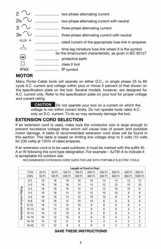
2 ........................ two-phase alternating current
2N ........................ two-phase alternating current with neutral
3 ........................ three-phase alternating current
3N ........................ three-phase alternating current with neutral
........................ rated current of the appropriate fuse-link in amperes
........................ time-lag miniature fuse-link where X is the symbol for the time/current characteristic, as given in IEC 60127
........................ protective earth
........................ class II toolIPXX ........................ IP symbol
EXTENSION CORD SELECTIONIf an extension cord is used, make sure the conductor size is large enough toprevent excessive voltage drop which will cause loss of power and possiblemotor damage. A table of recommended extension cord sizes will be found inthis section. This table is based on limiting line voltage drop to 5 volts (10 voltsfor 230 volts) at 150% of rated amperes.
If an extension cord is to be used outdoors, it must be marked with the suffix W-A or W following the cord type designation. For example – SJTW-A to indicate itis acceptable for outdoor use.
RECOMMENDED EXTENSION CORD SIZES FOR USE WITH PORTABLE ELECTRIC TOOLS
Length of Cord in Feet115V 25 Ft. 50 Ft. 100 Ft. 150 Ft. 200 Ft. 250 Ft. 300 Ft. 400 Ft. 500 Ft.230V 50 Ft. 100 Ft. 200 Ft. 300 Ft. 400 Ft. 500 Ft. 600 Ft. 800 Ft. 1000 Ft.
0-2 18 18 18 16 16 14 14 12 122-3 18 18 16 14 14 12 12 10 103-4 18 18 16 14 12 12 10 10 84-5 18 18 14 12 12 10 10 8 85-6 18 16 14 12 10 10 8 8 66-8 18 16 12 10 10 8 6 6 68-10 18 14 12 10 8 8 6 6 4
10-12 16 14 10 8 8 6 6 4 412-14 16 12 10 8 6 6 6 4 214-16 16 12 10 8 6 6 4 4 216-18 14 12 8 8 6 4 4 2 218-20 14 12 8 6 6 4 4 2 2
Nam
epla
te A
mp
ere
Rat
ing
MOTORMany Porter-Cable tools will operate on either D.C., or single phase 25 to 60cycle A.C. current and voltage within plus or minus 5 percent of that shown onthe specification plate on the tool. Several models, however, are designed forA.C. current only. Refer to the specification plate on your tool for proper voltageand current rating.
Do not operate your tool on a current on which thevoltage is not within correct limits. Do not operate tools rated A.C.only on D.C. current. To do so may seriously damage the tool.
SAVE THESE INSTRUCTIONS!

8
FOREWORDModel 513 Lock Mortiser permits builders and contractors to quickly cuttrue, accurate mortises for door box locks.
Model 517 Lock Face Templet allows quick and economical routing for lockfaces on doors after the mortise cut for the lock itself has been completed.
FUNCTIONAL DESCRIPTION
ASSEMBLY
Fig. 1
* Four height rod sections* Two cutting bits* Open end wrench* Two flat washers
* Two cap screws* Allen Wrench* Motor unit* Mortiser frame
CARTON CONTENTS
STANDARD EQUIPMENT With the mortiser, the four sections of the height rod (A), and two bits (B) arefurnished. See Fig. 1.
ASSEMBLY TOOLS REQUIRED - Allen wrench (supplied)
ASSEMBLY TIME ESTIMATE 15 to 30 minutes
ASSEMBLY OF BASE UNITThe unit is shipped with the crank handle disassembled.
Remove bolt and washer (B and C) Fig. 2. Place crank handle (D) onto crankshaft (A) with wooden knob facing outward and “D”-shaped hole in handlealigned with flat on shaft. Place bolt (C) through washer (B) and thread intoshaft (A). Tighten securely.
A
B
9
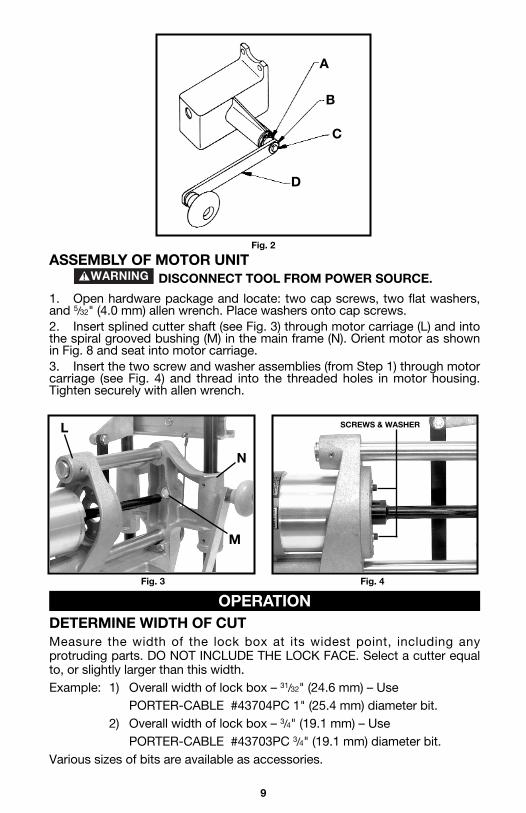
ASSEMBLY OF MOTOR UNITDISCONNECT TOOL FROM POWER SOURCE.
1. Open hardware package and locate: two cap screws, two flat washers,and 5/32" (4.0 mm) allen wrench. Place washers onto cap screws.2. Insert splined cutter shaft (see Fig. 3) through motor carriage (L) and intothe spiral grooved bushing (M) in the main frame (N). Orient motor as shownin Fig. 8 and seat into motor carriage.3. Insert the two screw and washer assemblies (from Step 1) through motorcarriage (see Fig. 4) and thread into the threaded holes in motor housing.Tighten securely with allen wrench.
DETERMINE WIDTH OF CUTMeasure the width of the lock box at its widest point, including anyprotruding parts. DO NOT INCLUDE THE LOCK FACE. Select a cutter equalto, or slightly larger than this width.Example: 1) Overall width of lock box – 31/32" (24.6 mm) – Use
PORTER-CABLE #43704PC 1" (25.4 mm) diameter bit.2) Overall width of lock box – 3/4" (19.1 mm) – Use
PORTER-CABLE #43703PC 3/4" (19.1 mm) diameter bit.Various sizes of bits are available as accessories.
OPERATION
Fig. 2
A
B
C
D
L
N
M
Fig. 3 Fig. 4
SCREWS & WASHER
10
DISCONNECT TOOL FROM POWER SOURCE andexercise extreme care when handling cutter to avoid bodily injury ordamage to cutting edge.
Thread selected bit onto end of splined cutter shaft and tighten securely.
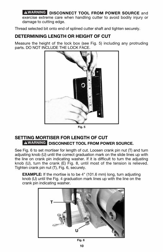
DETERMINING LENGTH OR HEIGHT OF CUT
Measure the height of the lock box (see Fig. 5) including any protrudingparts. DO NOT INCLUDE THE LOCK FACE.
SETTING MORTISER FOR LENGTH OF CUTDISCONNECT TOOL FROM POWER SOURCE.
See Fig. 6 to set mortiser for length of cut. Loosen crank pin nut (T) and turnadjusting knob (U) until the correct graduation mark on the slide lines up withthe line on crank pin indicating washer. If it is difficult to turn the adjustingknob (U), turn the crank (E) Fig. 8, until most of the tension is relieved.Tighten crank pin nut (T), Fig. 6, securely.
EXAMPLE: If the mortise is to be 4" (101.6 mm) long, turn adjustingknob (U) until the Fig. 4 graduation mark lines up with the line on thecrank pin indicating washer.
Fig. 5
Fig. 6
T
U
11
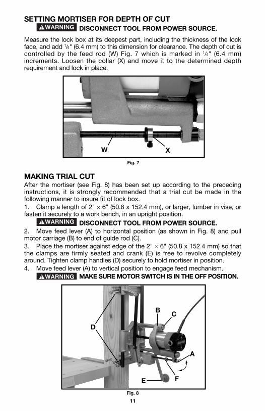
SETTING MORTISER FOR DEPTH OF CUTDISCONNECT TOOL FROM POWER SOURCE.
Measure the lock box at its deepest part, including the thickness of the lockface, and add 1/4" (6.4 mm) to this dimension for clearance. The depth of cut iscontrolled by the feed rod (W) Fig. 7 which is marked in 1/4" (6.4 mm)increments. Loosen the collar (X) and move it to the determined depthrequirement and lock in place.
MAKING TRIAL CUTAfter the mortiser (see Fig. 8) has been set up according to the precedinginstructions, it is strongly recommended that a trial cut be made in thefollowing manner to insure fit of lock box.1. Clamp a length of 2" × 6" (50.8 x 152.4 mm), or larger, lumber in vise, orfasten it securely to a work bench, in an upright position.
DISCONNECT TOOL FROM POWER SOURCE.2. Move feed lever (A) to horizontal position (as shown in Fig. 8) and pullmotor carriage (B) to end of guide rod (C).3. Place the mortiser against edge of the 2" × 6" (50.8 x 152.4 mm) so thatthe clamps are firmly seated and crank (E) is free to revolve completelyaround. Tighten clamp handles (D) securely to hold mortiser in position.4. Move feed lever (A) to vertical position to engage feed mechanism.
MAKE SURE MOTOR SWITCH IS IN THE OFF POSITION.
Fig. 7
W X
Fig. 8
D
B C
A
FE
12
5. Connect mortiser to power source.6. Turn motor switch ON and rotate crank (E) until collar (F) hits feedhousing, stopping depth of cut and completing mortise.7. Turn motor OFF.
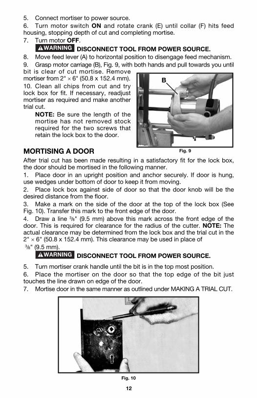
DISCONNECT TOOL FROM POWER SOURCE.8. Move feed lever (A) to horizontal position to disengage feed mechanism.9. Grasp motor carriage (B), Fig. 9, with both hands and pull towards you untilbit is clear of cut mortise. Removemortiser from 2" × 6" (50.8 x 152.4 mm).10. Clean all chips from cut and trylock box for fit. If necessary, readjustmortiser as required and make anothertrial cut.
NOTE: Be sure the length of themortise has not removed stockrequired for the two screws thatretain the lock box to the door.
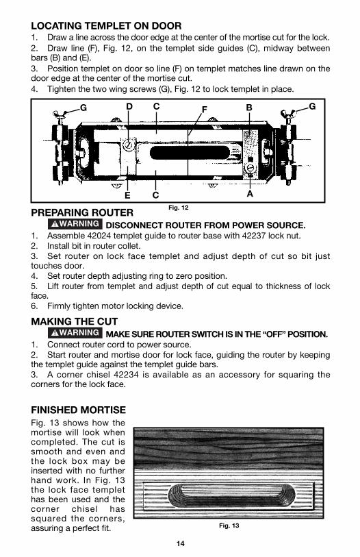
MORTISING A DOORAfter trial cut has been made resulting in a satisfactory fit for the lock box,the door should be mortised in the following manner.1. Place door in an upright position and anchor securely. If door is hung,use wedges under bottom of door to keep it from moving.2. Place lock box against side of door so that the door knob will be thedesired distance from the floor.3. Make a mark on the side of the door at the top of the lock box (See Fig. 10). Transfer this mark to the front edge of the door.4. Draw a line 3/8" (9.5 mm) above this mark across the front edge of thedoor. This is required for clearance for the radius of the cutter. NOTE: Theactual clearance may be determined from the lock box and the trial cut in the2" × 6" (50.8 x 152.4 mm). This clearance may be used in place of3/8" (9.5 mm).
DISCONNECT TOOL FROM POWER SOURCE.
5. Turn mortiser crank handle until the bit is in the top most position.6. Place the mortiser on the door so that the top edge of the bit justtouches the line drawn on edge of the door.7. Mortise door in the same manner as outlined under MAKING A TRIAL CUT.
Fig. 9
B
Fig. 10

13
PRODUCTION LOCK MORTISINGIf you have a number of doors with the locks at the same height, the heightrod attachment (see Fig. 11) will be of great value. After you have determinedthe height you want, and have the lock mortiser in position on the first door,assemble the four rods that compose the height rod attachment. Insert therods in the mortiser and place the height rod stop (G) on the top of the rod soit rests on the top of the door. Lock the height rod screws, (H) Fig. 11A. Tolocate the mortiser on the next door, simply place the mortiser on the doorwith the height rod stop resting on the top of the door and tighten theclamps. This will assure having all locks located in the same position.
MODEL 517 LOCK FACE TEMPLETREQUIRED EQUIPMENT Equipment required for use with Router and Lock Face Templet.
42024 Templet Guide (included)42237 Locknut (Included)43440PC 5/8" (15.9 mm) Diameter Straight Bit (not included)
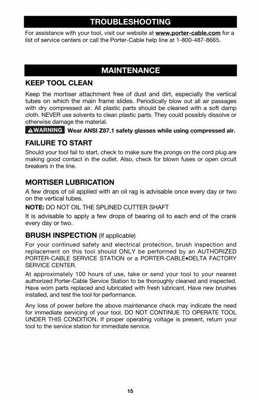
SETTING UP TEMPLET 1. Loosen locking screw (A), Fig. 12. 2. Adjust side guides (C), Fig. 12, so the space between them is 1/8"
(3.2 mm) wider than the lock face. 3. Firmly tighten screw (A). 4. Loosen locking screw (D), Fig. 12. 5. Adjust guide bar (E), Fig. 12, distance between (E) and (B) is
1/8" (3.2 mm) longer than the lock face. 6. Firmly tighten screw (D).
Fig. 11
Fig. 11A
G
H
14
LOCATING TEMPLET ON DOOR 1. Draw a line across the door edge at the center of the mortise cut for the lock. 2. Draw line (F), Fig. 12, on the templet side guides (C), midway betweenbars (B) and (E). 3. Position templet on door so line (F) on templet matches line drawn on thedoor edge at the center of the mortise cut. 4. Tighten the two wing screws (G), Fig. 12 to lock templet in place.
PREPARING ROUTERDISCONNECT ROUTER FROM POWER SOURCE.
1. Assemble 42024 templet guide to router base with 42237 lock nut. 2. Install bit in router collet. 3. Set router on lock face templet and adjust depth of cut so bit justtouches door.4. Set router depth adjusting ring to zero position. 5. Lift router from templet and adjust depth of cut equal to thickness of lockface. 6. Firmly tighten motor locking device.
MAKING THE CUT MAKE SURE ROUTER SWITCH IS IN THE “OFF” POSITION.
1. Connect router cord to power source. 2. Start router and mortise door for lock face, guiding the router by keepingthe templet guide against the templet guide bars. 3. A corner chisel 42234 is available as an accessory for squaring thecorners for the lock face.
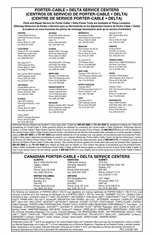
FINISHED MORTISE Fig. 13 shows how themortise will look whencompleted. The cut issmooth and even andthe lock box may beinserted with no furtherhand work. In Fig. 13the lock face templethas been used and thecorner chisel hassquared the corners,assuring a perfect fit.
Fig. 12
G GD
E C A
C F B
Fig. 13
15
For assistance with your tool, visit our website at www.porter-cable.com for alist of service centers or call the Porter-Cable help line at 1-800-487-8665.
TROUBLESHOOTING
KEEP TOOL CLEAN
Keep the mortiser attachment free of dust and dirt, especially the verticaltubes on which the main frame slides. Periodically blow out all air passageswith dry compressed air. All plastic parts should be cleaned with a soft dampcloth. NEVER use solvents to clean plastic parts. They could possibly dissolve orotherwise damage the material.
Wear ANSI Z87.1 safety glasses while using compressed air.
FAILURE TO STARTShould your tool fail to start, check to make sure the prongs on the cord plug aremaking good contact in the outlet. Also, check for blown fuses or open circuitbreakers in the line.
MORTISER LUBRICATIONA few drops of oil applied with an oil rag is advisable once every day or twoon the vertical tubes.NOTE: DO NOT OIL THE SPLINED CUTTER SHAFTIt is advisable to apply a few drops of bearing oil to each end of the crankevery day or two.
BRUSH INSPECTION (If applicable)For your continued safety and electrical protection, brush inspection andreplacement on this tool should ONLY be performed by an AUTHORIZEDPORTER-CABLE SERVICE STATION or a PORTER-CABLE•DELTA FACTORYSERVICE CENTER.
At approximately 100 hours of use, take or send your tool to your nearestauthorized Porter-Cable Service Station to be thoroughly cleaned and inspected.Have worn parts replaced and lubricated with fresh lubricant. Have new brushesinstalled, and test the tool for performance.
Any loss of power before the above maintenance check may indicate the needfor immediate servicing of your tool. DO NOT CONTINUE TO OPERATE TOOLUNDER THIS CONDITION. If proper operating voltage is present, return yourtool to the service station for immediate service.
MAINTENANCE

16
PORTER-CABLE LIMITEDONE YEAR WARRANTY
Porter-Cable warrants its Professional Power Tools for a period of one year from the date of originalpurchase. We will repair or replace at our option, any part or parts of the product and accessoriescovered under this warranty which, after examination, proves to be defective in workmanship ormaterial during the warranty period. For repair or replacement return the complete tool or accessory,transportation prepaid, to your nearest Porter-Cable Service Center or Authorized Service Station.Proof of purchase may be required. This warranty does not apply to repair or replacement requireddue to misuse, abuse, normal wear and tear or repairs attempted or made by other than our ServiceCenters or Authorized Service Stations.
ANY IMPLIED WARRANTY, INCLUDING THE IMPLIED WARRANTIES OF MERCHANTABILITY ANDFITNESS FOR A PARTICULAR PURPOSE, WILL LAST ONLY FOR ONE (1) YEAR FROM THE DATEOF PURCHASE.
To obtain information on warranty performance please write to: PORTER-CABLE CORPORATION,4825 Highway 45 North, Jackson, Tennessee 38305; Attention: Product Service. THE FOREGOINGOBLIGATION IS PORTER-CABLE’S SOLE LIABILITY UNDER THIS OR ANY IMPLIED WARRANTYAND UNDER NO CIRCUMSTANCES SHALL PORTER-CABLE BE LIABLE FOR ANY INCIDENTALOR CONSEQUENTIAL DAMAGES. Some states do not allow limitations on how long an impliedwarranty lasts or the exclusion or limitation of incidental or consequential damages, so the abovelimitation or exclusion may not apply to you.
This warranty gives you specific legal rights and you may also have other legal rights which varyfrom state to state.
WARRANTY
A complete line of accessories is available from your Porter-Cable•DeltaSupplier, Porter-Cable•Delta Factory Service Centers, and Porter-CableAuthorized Service Stations. Please visit our Web Site www.porter-cable.comfor a catalog or for the name of your nearest supplier.
Since accessories other than those offered byPorter-Cable•Delta have not been tested with this product, use ofsuch accessories could be hazardous. For safest operation, onlyPorter-Cable•Delta recommended accessories should be usedwith this product.
ACCESSORIES
REPLACEMENT PARTSWhen servicing use only identical replacement parts. For a service parts list or tolearn more about Porter-Cable visit our website at www.porter-cable.com
SERVICE AND REPAIRSAll quality tools will eventually require servicing, or replacement of parts due towear from normal use. For assistance with your tool, visit our website atwww.porter-cable.com for a list of service centers or call the Customer CareDepartment at 1-800-487-8665. All repairs made by our service centers are fullyguaranteed against defective material and workmanship. We cannot guaranteerepairs made or attempted by others.
Should you have any questions about your tool, feel free to write us at any time.In any communications, please give all information shown on the nameplate ofyour tool (model number, type, serial number, etc.).
SERVICE
The following are trademarks of PORTER-CABLE • DELTA (Las siguientes son marcas registradas de PORTER-CABLE • DELTA S.A.) (Lesmarques suivantes sont des marques de fabriquant de la PORTER-CABLE • DELTA): Auto-Set®, BAMMER®, B.O.S.S.®, Builder’s Saw®,Contractor’s Saw®, Contractor’s Saw II™, Delta®, DELTACRAFT®, DELTAGRAM™, Delta Series 2000™, DURATRONIC™, Emc²™, FLEX®, FlyingChips™, FRAME SAW®, Grip Vac™, Homecraft®, INNOVATION THAT WORKS®, Jet-Lock®, JETSTREAM®, ‘kickstand®, LASERLOC®, MICRO-SET®, Micro-Set®, MIDI LATHE®, MORTEN™, NETWORK™, OMNIJIG®, POCKET CUTTER®, PORTA-BAND®, PORTA-PLANE®, PORTER-CABLE®&(design), PORTER-CABLE®PROFESSIONAL POWER TOOLS, PORTER-CABLE REDEFINING PERFORMANCE™, Posi-Matic®, Q-3®&(design), QUICKSAND®&(design), QUICKSET™, QUICKSET II®, QUICKSET PLUS™, RIPTIDE™&(design), SAFE GUARD II®, SAFE-LOC®,Sanding Center®, SANDTRAP®&(design), SAW BOSS®, Sawbuck™, Sidekick®, SPEED-BLOC®, SPEEDMATIC®, SPEEDTRONIC®, STAIR EASE®,The American Woodshop®&(design), The Lumber Company®&(design), THE PROFESSIONAL EDGE®, THE PROFESSIONAL SELECT®, THIN-LINE™, TIGER®, TIGER CUB®, TIGER SAW®, TORQBUSTER®, TORQ-BUSTER®, TRU-MATCH™, TWIN-LITE®, UNIGUARD®, Unifence®,UNIFEEDER™, Unihead®, Uniplane™, Unirip®, Unisaw®, Univise®, Versa-Feeder®, VERSA-PLANE® , WHISPER SERIES®,WOODWORKER’S CHOICE™. Trademarks noted with ™ and ® are registered in the United States Patent and Trademark Office and may also be registered in other countries.Las Marcas Registradas con el signo de ™ y ® son registradas por la Oficina de Registros y Patentes de los Estados Unidos y también puedenestar registradas en otros países. Marques déposées, indiquées par la lettre ™ et ®, sont déposées au Bureau des brevets d’invention etmarques déposées aux Etats-Unis et pourraient être déposées aux autres pays.
PORTER-CABLE • DELTA SERVICE CENTERS(CENTROS DE SERVICIO DE PORTER-CABLE • DELTA)
(CENTRE DE SERVICE PORTER-CABLE • DELTA)Parts and Repair Service for Porter-Cable • Delta Power Tools are Available at These Locations
(Obtenga Refaccion de Partes o Servicio para su Herramienta en los Siguientes Centros de Porter-Cable • Delta)(Locations où vous trouverez les pièces de rechange nécessaires ainsi qu’un service d’entretien)
Authorized Service Stations are located in many large cities. Telephone 800-487-8665 or 731-541-6042 for assistance locating one. Parts andaccessories for Porter-Cable • Delta products should be obtained by contacting any Porter-Cable • Delta Distributor, Authorized ServiceCenter, or Porter-Cable • Delta Factory Service Center. If you do not have access to any of these, call 888-848-5175 and you will be directed tothe nearest Porter-Cable • Delta Factory Service Center. Las Estaciones de Servicio Autorizadas están ubicadas en muchas grandes ciudades.Llame al 800-487-8665 ó al 731-541-6042 para obtener asistencia a fin de localizar una. Las piezas y los accesorios para los productos Porter-Cable • Delta deben obtenerse poniéndose en contacto con cualquier distribuidor Porter-Cable • Delta, Centro de Servicio Autorizado o Centrode Servicio de Fábrica Porter-Cable • Delta. Si no tiene acceso a ninguna de estas opciones, llame al 888-848-5175 y le dirigirán al Centro deServicio de Fábrica Porter-Cable • Delta más cercano. Des centres de service agréés sont situés dans beaucoup de grandes villes. Appelez au800-487-8665 ou au 731-541-6042 pour obtenir de l’aide pour en repérer un. Pour obtenir des pièces et accessoires pour les produits Porter-Cable • Delta, s’adresser à tout distributeur Porter-Cable • Delta, centre de service agréé ou centre de service d’usine Porter-Cable • Delta. Sivous n’avez accès à aucun de ces centres, appeler le 888-848-5175 et on vous dirigera vers le centre de service d’usine Porter-Cable • Delta leplus proche.
PC7.2-0105-164
CANADIAN PORTER-CABLE • DELTA SERVICE CENTERSALBERTABay 6, 2520-23rd St. N.E.Calgary, AlbertaT2E 8L2Phone: (403) 735-6166Fax: (403) 735-6144
BRITISH COLUMBIA8520 Baxter PlaceBurnaby, B.C.V5A 4T8Phone: (604) 420-0102Fax: (604) 420-3522
MANITOBA1699 Dublin AvenueWinnipeg, ManitobaR3H 0H2Phone: (204) 633-9259Fax: (204) 632-1976
ONTARIO505 Southgate DriveGuelph, OntarioN1H 6M7Phone: (519) 767-4132Fax: (519) 767-4131
QUÉBEC1515 Ave.St-Jean Baptiste, Suite 160Québec, P.Q.G2E 5E2Phone: (418) 877-7112Fax: (418) 877-7123
1447, BeginSt-Laurent, (Mtl), P.Q.H4R 1V8Phone: (514) 336-8772Fax: (514) 336-3505
ARIZONATempe 85282 (Phoenix)2400 West Southern AvenueSuite 105Phone: (602) 437-1200Fax: (602) 437-2200
CALIFORNIAOntario 91761 (Los Angeles)3949A East Guasti RoadPhone: (909) 390-5555Fax: (909) 390-5554
San Diego 921117638 Clairemont Blvd.Phone: (858) 277-9595Fax: (858) 277-9696
San Leandro 94577 (Oakland)3039 Teagarden StreetPhone: (510) 357-9762Fax: (510) 357-7939
COLORADOArvada 80003 (Denver)8175 Sheridan Blvd., Unit SPhone: (303) 487-1809Fax: (303) 487-1868
FLORIDADavie 33314 (Miami)4343 South State Rd. 7 (441)Unit #107Phone: (954) 321-6635Fax: (954) 321-6638
Tampa 33609 4538 W. Kennedy BoulevardPhone: (813) 877-9585Fax: (813) 289-7948
GEORGIAForest Park 30297 (Atlanta)5442 Frontage Road,Suite 112Phone: (404) 608-0006Fax: (404) 608-1123
ILLINOISAddison 60101 (Chicago)400 South Rohlwing Rd.Phone: (630) 424-8805Fax: (630) 424-8895
Woodridge 60517 (Chicago)2033 West 75th StreetPhone: (630) 910-9200Fax: (630) 910-0360
MARYLANDElkridge 21075 (Baltimore)7397-102 Washington Blvd.Phone: (410) 799-9394Fax: (410) 799-9398
MASSACHUSETTSFranklin 02038 (Boston)Franklin Industrial Park101E Constitution Blvd.Phone: (508) 520-8802Fax: (508) 528-8089
MICHIGANMadison Heights 48071 (Detroit)30475 Stephenson HighwayPhone: (248) 597-5000Fax: (248) 597-5004
MINNESOTAMinneapolis 554295522 Lakeland Avenue NorthPhone: (763) 561-9080Fax: (763) 561-0653
MISSOURINorth Kansas City 641161141 Swift AvenuePhone: (816) 221-2070Fax: (816) 221-2897
St. Louis 631197574 Watson RoadPhone: (314) 968-8950Fax: (314) 968-2790
NEW YORKFlushing 11365-1595 (N.Y.C.)175-25 Horace Harding Expwy.Phone: (718) 225-2040Fax: (718) 423-9619
NORTH CAROLINACharlotte 282709129 Monroe Road, Suite 115Phone: (704) 841-1176Fax: (704) 708-4625
OHIOColumbus 432144560 Indianola AvenuePhone: (614) 263-0929Fax: (614) 263-1238
Cleveland 441258001 Sweet Valley DriveUnit #19Phone: (216) 447-9030Fax: (216) 447-3097
OREGONPortland 972304916 NE 122 nd Ave.Phone: (503) 252-0107Fax: (503) 252-2123
PENNSYLVANIAWillow Grove 19090 (Philadelphia)520 North York RoadPhone: (215) 658-1430Fax: (215) 658-1433
TEXASCarrollton 75006 (Dallas)1300 Interstate 35 N, Suite 112Phone: (972) 446-2996Fax: (972) 446-8157
Houston 770434321 Sam Houston Parkway, WestSuite 180Phone: (713) 983-9910Fax: (713) 983-6645
WASHINGTONAuburn 98001(Seattle)3320 West Valley HWY, NorthBuilding D, Suite 111Phone: (253) 333-8353Fax: (253) 333-9613