INSTRUCTION HANDBOOK Electric Stacker
28
Version 05/2018 PS 16W-SMS-006-EN INSTRUCTION HANDBOOK Electric Stacker WARNING Do not use the electric truck before reading and understanding these operating instructions. NOTE: Please check the designation of your present type at the last page of this document as well as on the ID-plate. Keep for future reference.
Transcript of INSTRUCTION HANDBOOK Electric Stacker

Version 05/2018
PS 16W-SMS-006-EN
INSTRUCTION HANDBOOK
Electric Stacker
WARNING Do not use the electric truck before reading and understanding these operating instructions.
NOTE:
Please check the designation of your
present type at the last page of this
document as well as on the ID-plate.
Keep for future reference.

1
FOREWORD Before operating the electric stacker, read this ORIGINAL INSTRUCTION HANDBOOK carefully and
understand the usage of the truck completely. Improper operation could create danger.
This handbook describes the usage of different electric stackers. When operating and servicing the truck,
make sure, that it applies to your type.
Chapter 11 describes specialized stipulations and regulations for the American market. Follow these instructions and stipulations if you operate the truck within the American market!
Keep this handbook for future reference. If this or the warning/ caution labels are damaged or got lost,
please contact your local dealer for replacement.
This truck complies with the requirements according to EN ISO 3691-1 (Industrial trucks- safety
requirements and verification, part 1), EN 12895 (Industrial trucks- electromagnetic compatibility), EN
12053 (Safety of industrial trucks- test methods for measuring noise emissions), EN 1175-1 (Industrial
truck safety – electrical requirements), assumed the truck is used according to the described purpose.
The noise level for this machine is 70 dB(A) according to EN 12053.
The vibration is 0.85 m/s2 (if equipped with a platform) according to EN 13059.
ATTENTION:
Environmentally hazardous waste, such as batteries, oil and electronics, will have a negative effect
on the environment, or health, if handled incorrectly.
The waste packages should be sorted and put into solid dustbins according to the materials and be
collected disposal by local special environment protection bureau. To avoid pollution, it’s forbidden to
throw away the wastes randomly.
To avoid leaking during the use of the products, the user should prepare some absorbable materials
(scraps of wooden or dry duster cloth) to absorb the leaking oil in time. To avoid second pollution to
the environment, the used absorbable materials should be handed in to special departments in terms
of local authorities.
Our products are subject to ongoing developments. Because this handbook is only for the purpose of
operating /servicing the stacker, therefore please have understanding, that there is no guarantee out
of particular features out of this handbook.
NOTE: On this manual, the left sign means warning and danger, which can lead to death or serious injury if not followed.
Copyright The copyright remains with the company, mentioned on the CE- certificate at the end of this document or,
if sold within the USA, with the company, mentioned on the company sticker.

2
TABLE OF CONTENTS 1. CORRECT APPLICATION ............................................................................................ 3 2. DESCRIPTION OF THE STACKER .............................................................................. 4
a. Overview of the main components ............................................................................. 4 b. Main technical data .................................................................................................... 5 c. Description of the safety devices and warning labels (Europe and other, excepting USA) ................................................................................................................................. 6 d. Identification plate ...................................................................................................... 7
3. WARNINGS, RESIDUAL RISK AND SAFETY INSTRUCTIONS .................................. 7 4. COMMISSIONING, TRANSPORTING, DECOMMISSIONING ...................................... 8
a. Commissioning .......................................................................................................... 8 b. Lifting/ Transportation ................................................................................................. 9 c. Decommissioning ....................................................................................................... 9
5. DAILY INSPECTION ..................................................................................................... 9 6. OPERATING INSTRUCTIONS ................................................................................... 10
a. Parking ..................................................................................................................... 10 b. Residual lift diagram................................................................................................. 10 c. Lifting ....................................................................................................................... 11 d. Lowering .................................................................................................................. 11 e. Travelling ................................................................................................................. 11 f. Steering .................................................................................................................... 12 g. Braking ..................................................................................................................... 12 h. Malfunctions ............................................................................................................. 13 i. Emergency ............................................................................................................... 13
7. BATTERY CHARGING AND REPLACEMENT ........................................................... 13 a. Replacement ............................................................................................................ 14 b. Battery Indicator ....................................................................................................... 14 c. Charging .................................................................................................................. 14
8. REGULAR MAINTENANCE ........................................................................................ 15 a. Maintenance checklist .............................................................................................. 15 b. Lubricating points ..................................................................................................... 17 c. Check and refill hydraulic oil .................................................................................... 17 d. Checking electrical fuses ......................................................................................... 18 e. Removing, reattaching guarding .............................................................................. 18
9. TROUBLE SHOOTING ............................................................................................... 18 10. WIRING/ CIRCUIT DIAGRAM ..................................................................................... 20
a. Electrical circuit diagram .......................................................................................... 20 b. Hydraulic circuit ........................................................................................................ 22
11. SPECIALIZED STIPULATIONS FOR THE US- AMERICAN MARKET ....................... 23 a. Foreword/ Compliance ............................................................................................. 23 b. Description warning labels (only US- market) .......................................................... 24
12. DECLARATION OF CONFORMITY (valid, if sold within the EU) ................................ 26
3
1. CORRECT APPLICATION It is only allowed to use this electric stacker according to this instruction handbook.
The trucks described in this handbook are self propelled pedestrian controlled electric power stacker,
with electrically powered low height lifting function. The trucks are designed for stacking operations in
dedicated racking by lifting and lowering the palletized load up to the desired lifting height.
A wrong usage can cause human injuries or can damage equipment.
The operator/ the operating company has to ensure the correct usage and has to ensure, that this truck
is used only by staff, which is trained and authorized to use this truck.
The truck has to be used on substantially firm, smooth, prepared, level and adequate surfaces. The truck
is intended to be used for indoor applications with ambient temperatures between +5C and + 40C and
for medium applications without crossing permanent obstacles or potholes. Operating on ramps is not
allowed. While operating, the load must be placed approximately on the longitudinal centre plane of the
stacker.
Lifting or transporting people is forbidden. If travelling the load must be lowered to the lifting point.
It is not allowed to use this truck on tail lifts or loading ramps.
The capacity is marked on the load diagram as well on the Identification plate. The operator has to
consider the warnings and safety instructions.
Operating lighting must be minimum 50 Lux.
Modification
No modifications or alterations to this truck which may affect, for example, capacity, stability or safety
requirements of the truck, shall be made without the prior written approval of the original truck
manufacturer, its authorized representative, or a successor thereof. This includes changes affecting, for
example braking, steering, visibility and the addition of removable attachments. When the manufacturer
or its successor approve a modification or alteration, they shall also make and approve appropriate
changes to capacity plate, decals, tags and operation and maintenance handbooks.
By not observing these instructions, the warranty becomes void.

4
Fig. 1: Overview main components
2. DESCRIPTION OF THE STACKER
a. Overview of the main components
1. Key switch
2. Discharge indicator and charging indicating
LED
3. Emergency button
4. Foldable platform
5. Main cover
6. Protective arm cover
7. Protective arm
8. Upper cover
9. Middle cover
10. Protective screen
11. Chain
12. Mast
13. Hydraulic cylinder
14. Battery cover
15. Battery
16. Load wheels
17. Safety (belly) button
18. Accelerator (butterfly button)
19. Tiller
20. Forks
21. Drive wheel
22. Castors
23. Load backrest

5
b. Main technical data
Table1: Main technical data for standard version Type sheet for industrial truck acc. to VDI 2198
Dis
tin
gu
ish
ing
m
ark
1.2 Manufacturer`s type designation PS 16W
1.3 Power (battery ,diesel, petrol, gas, manual) Battery1.4 Operator type Pedestrian (stand)1.5 Load Capacity / rated load Q (t) 1.6
1.6 Load centre distance C (mm) 600
1.8 Load distance ,centre of drive axle to fork X (mm) 784
1.9 Wheelbase Y (mm) 1336
Wei
gh
t
2.1 Service weight kg 1450
2.2 Axle loading, laden front/rear kg 1400/1650
2.3 Axle loading, unladen front/rear kg 1130/320
Tir
es, C
has
sis 3.1 Tires Polyurethane (PU)
3.2 Tire size, front x w (mm) 252 × 88 3.3 Tire size, rear x w (mm) 80 × 70 3.4 Additional wheels(dimensions) x w (mm) 150× 54 3.5 Wheels, number front/rear(x=driven wheels) 1x+2 / 4
3.6 Tread, front b10 (mm) 790
3.7 Tread, rear b11 (mm) 390/ 505
Dim
ensi
on
s
4.2 Lowered mast height h1 (mm) 2102
4.3 Free Lift height h2 (mm) -
4.4 Lift h3 (mm) 4600
4.5 Extended mast height h4 (mm) 5414
4.9 Height of tiller in drive position min./ max. h14 (mm) 961/ 1396
Fig. 2: Technical data
6
4.15 Height, lowered h13 (mm) 85
4.19 Overall length l1 (mm) 1895/1995
4.20 Length to face of forks l2 (mm) 746/846
4.21 Overall width b1 (mm) 1050
4.22 Fork dimensions s/e/l (mm) 60/180/1150
4.25 Distance between fork- arms b5 (mm) 570/ 685
4.32 Ground clearance, centre of wheelbase m2 (mm) 25
4.33 Aisle width for pallets 1000X1200 crossways Ast (mm) 2400/ 2500
4.34 Aisle width for pallets 800X1200 lengthways Ast (mm) 2350/ 2450
4.35 Turning radius Wa (mm) 1550/ 1650
Per
form
an
ce d
ata
5.1 Travel speed, laden/ unladen km/h 6.0 / 6.0
5.2 Lift speed, laden/ unladen m/s 0.10/0.16
5.3 Lowering speed, laden/ unladen m/s 0.095/0.12
5.8 Max. gradeability, laden/ unladen % 6 / 12
5.10 Service brake Electromagnetic
Ele
ctri
c-
Mo
tor
6.1 Drive motor rating S2 60min kW 1.3
6.2 Lift motor rating at S3 15% kW 3.0
6.3 Battery acc. to DIN 43 531/35/36 A,B,C,no No, cells 4PzS
6.4 Battery voltage, nominal capacity K5 V/Ah 24/ 280
6.5 Battery weight kg 250
6.6 Energy consumption acc. to VDI cycle kWh/h 1.4
Ad
dit
ion
al
dat
a 8.1 Type of drive control AC- speed control
8.4 sound level at driver`s ear acc. to EN 12053 dB(A) 70
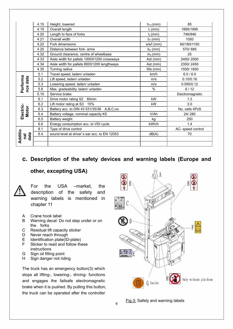
c. Description of the safety devices and warning labels (Europe and
other, excepting USA)
For the USA –market, the description of the safety and warning labels is mentioned in chapter 11
A Crane hook label B Warning decal: Do not step under or on
the forks C Residual lift capacity sticker D Never reach through E Identification plate(ID-plate) F Sticker to read and follow these
instructions G Sign oil filling point H Sign danger not riding
The truck has an emergency button(3) which
stops all lifting-, lowering-, driving- functions
and engages the failsafe electromagnetic
brake when it is pushed. By pulling this button,
the truck can be operated after the controller
Fig.3: Safety and warning labels

7
checked the functions. Before operating, insert the key and turn the key switch (1) clockwise. To prevent
against unauthorized access, turn the key anti-clockwise and remove it, if you not operate this truck. The
truck is equipped with a safety (belly) button (17) which switches the driving function away from the
operator, if the truck travels towards the operator and the tiller is activated in the tillers operating zone.
Follow also the instructions given on the decals. Replace the decals if they are damaged or missing.
d. Identification plate
1 Designation, type
2 Serial number
3 Rated capacity in kg
4 Supply voltage in V
5 Own mass (self weight) in kg without battery
6 Name and address of manufacturer)
7 Battery weight minimum/ maximum
8 Nominal power in kW
9 Load center distance
10 Manufacturing data
11 Option
3. WARNINGS, RESIDUAL RISK AND SAFETY INSTRUCTIONS
DO NOT
Drive outside the stacking operation with a lifted load higher than the lifting point.
Put foot or hand under or into the lifting mechanism.
Allow other person than the operator to stand in front of or behind the truck when it is
moving or lifting/lowering.
Overload the truck.
Put foot in front of the wheels, injury could result.
Lift people. People could fall down and suffer severe injury.
Push or pull loads.
Use this truck on ramps.
1
2
3
4
5
11
10
9
If sold to the EU, here the place of
the CE marking
6
8
7
Fig. 4: Identification plate
8
Use the truck without a removed protective screen (fig.1, pos.10/ guarding).
Side or end load. Load must be distributed evenly on the forks.
Use the truck with unstable, unbalanced not stable load.
Use truck without manufacturer’s written consent.
Lifted loads could become unstable at wind forces. In the case of wind forces do not
lift the load if there is any influence to the stability.
Watch difference in floor levels when driving. Load could fall down or the truck could get uncontrollable.
Keep watching the condition of load. Stop operating the truck if load becomes unstable. Brake the truck
and activate the emergency button (3) by pushing when sliding load on or off the truck. If the truck has
any malfunctions, follow chapter 8.
Practice maintenance work according to regular inspection. This truck is not designed to be water
resistant. Use the truck under dry condition. Prolonged continuous operation might cause damage of the
power pack. Stop operation if temperature of hydraulic oil is too high.
When operating the truck, the operator has to wear safety shoes. The truck is intended to be used for indoor applications with ambient temperatures
between +5C and + 40C. The operating lighting must be minimum 50 Lux. It is not allowed to use the truck on ramps. To prevent unintended sudden movements when not operating the truck (i.e. from
another person, etc.) switch off the truck and remove the key.
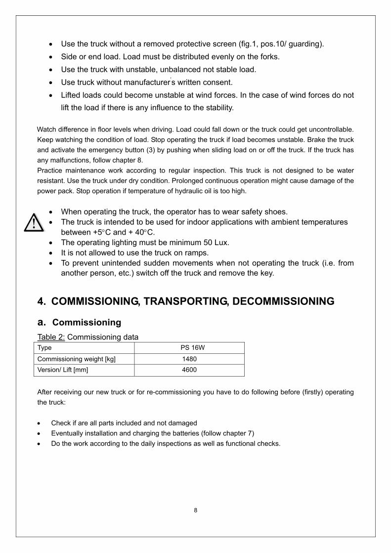
4. COMMISSIONING, TRANSPORTING, DECOMMISSIONING
a. Commissioning
Table 2: Commissioning data Type PS 16W
Commissioning weight [kg] 1480
Version/ Lift [mm] 4600
After receiving our new truck or for re-commissioning you have to do following before (firstly) operating
the truck:
Check if are all parts included and not damaged
Eventually installation and charging the batteries (follow chapter 7)
Do the work according to the daily inspections as well as functional checks.
9
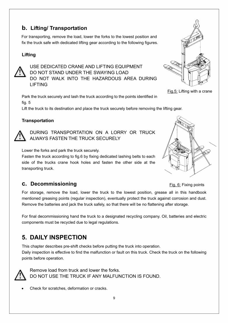
b. Lifting/ Transportation
For transporting, remove the load, lower the forks to the lowest position and
fix the truck safe with dedicated lifting gear according to the following figures.
Lifting USE DEDICATED CRANE AND LIFTING EQUIPMENT DO NOT STAND UNDER THE SWAYING LOAD DO NOT WALK INTO THE HAZARDOUS AREA DURING LIFTING
Park the truck securely and lash the truck according to the points identified in
fig. 5
Lift the truck to its destination and place the truck securely before removing the lifting gear.
Transportation
DURING TRANSPORTATION ON A LORRY OR TRUCK ALWAYS FASTEN THE TRUCK SECURELY
Lower the forks and park the truck securely.
Fasten the truck according to fig.6 by fixing dedicated lashing belts to each
side of the trucks crane hook holes and fasten the other side at the
transporting truck.
c. Decommissioning
For storage, remove the load, lower the truck to the lowest position, grease all in this handbook
mentioned greasing points (regular inspection), eventually protect the truck against corrosion and dust.
Remove the batteries and jack the truck safely, so that there will be no flattening after storage.
For final decommissioning hand the truck to a designated recycling company. Oil, batteries and electric
components must be recycled due to legal regulations.
5. DAILY INSPECTION This chapter describes pre-shift checks before putting the truck into operation.
Daily inspection is effective to find the malfunction or fault on this truck. Check the truck on the following
points before operation.
Remove load from truck and lower the forks. DO NOT USE THE TRUCK IF ANY MALFUNCTION IS FOUND.
Check for scratches, deformation or cracks.
Fig.5: Lifting with a crane
Fig. 6: Fixing points

10
Check if there is any oil leakage from the cylinder.
Check the vertical creep of the truck.
Check the chain and rollers for damages or corrosion.
Check the smooth movement of the wheels.
Check the function of the emergency brake by activating the emergency button.
Check, the tiller arm- switch braking function
Check the lifting and lowering functions by operating the buttons.
Check if the protective screen has no damages and that is correctly assembled.
Check the audio warning signal.
Check if all bolts and nuts are tightened firmly.
Check the function of the key switch.
Check the speed limitation switch.
Visual check if there are any broken hoses or broken electric wires.
If supplied with a backrest extension, check it for
damages and correct assembling.
6. OPERATING INSTRUCTIONS BEFORE OPERATING THIS TRUCK, PLEASE FOLLOW THE WARNINGS AND SAFETY INSTRUCTIONS (CHAPTER 3). BEFORE OPERATING THIS TRUCK, ENSURE THAT THE LOAD OR OTHER EQUIPMENT NOT CAUSES INSUFFICIENT VISIBILITY!
Make sure, that the load is palletized and stable and that the daily inspection is
carried out. For starting, insert the key and turn it clockwise to the “ON”- position.
Eventually before inserting the key, the emergency button must be pulled
carefully.
Press the horn button (24) to activate the audible warning signal.
a. Parking
DO NOT PARK THE TRUCK ON INCLINED SURFACES The truck is equipped with an electromagnetic failsafe stopping and parking
brake.
Always lower the forks fully and drive the truck to a safe area. Turn the key
anti- clockwise to the “Off” – position and remove the key.
b. Residual lift diagram
The residual lift diagram indicates the maximum capacity Q [kg] for a
given load centre c [mm] and the corresponding lift height H [mm] for the
Fig.8: Key switch
Fig.7: Tiller operating controls
17
18
24
25
Fig. 9: Residual lift diagram
11
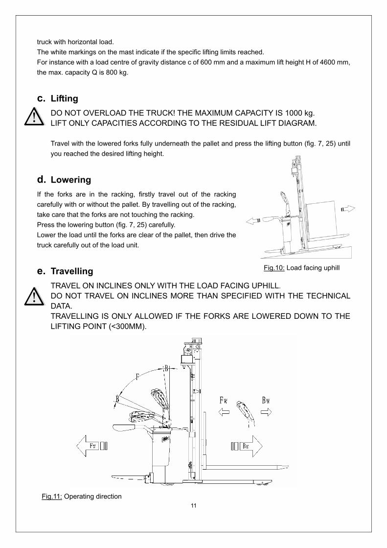
truck with horizontal load.
The white markings on the mast indicate if the specific lifting limits reached.
For instance with a load centre of gravity distance c of 600 mm and a maximum lift height H of 4600 mm,
the max. capacity Q is 800 kg.
c. Lifting
DO NOT OVERLOAD THE TRUCK! THE MAXIMUM CAPACITY IS 1000 kg. LIFT ONLY CAPACITIES ACCORDING TO THE RESIDUAL LIFT DIAGRAM.
Travel with the lowered forks fully underneath the pallet and press the lifting button (fig. 7, 25) until
you reached the desired lifting height.
d. Lowering
If the forks are in the racking, firstly travel out of the racking
carefully with or without the pallet. By travelling out of the racking,
take care that the forks are not touching the racking.
Press the lowering button (fig. 7, 25) carefully.
Lower the load until the forks are clear of the pallet, then drive the
truck carefully out of the load unit.
e. Travelling
TRAVEL ON INCLINES ONLY WITH THE LOAD FACING UPHILL.
DO NOT TRAVEL ON INCLINES MORE THAN SPECIFIED WITH THE TECHNICAL DATA. TRAVELLING IS ONLY ALLOWED IF THE FORKS ARE LOWERED DOWN TO THE LIFTING POINT (<300MM).
Fig.10: Load facing uphill
Fig.11: Operating direction
12
After starting the truck by turning the inserted key to the “ON”- position (fig. 8) and eventually by pulling
the emergency button carefully, move the tiller to the operating zone (‘F’, fig.11).
Turn the accelerator button to the desired direction forward ‘Fw.’ Or backwards ‘Bw.’(fig. 11).
Control the travelling speed by moving the accelerator button (18) carefully until you reached the desired
speed.
If you move the accelerator button back to the neutral position, the controller decelerates the truck until
the truck stops. If the truck stopped, the parking brake will be engaged.
Drive carefully the truck to the destination. Watch the route conditions and adjust the travelling speed
with the accelerator button.
THE TRUCK CAN BE EQUIPPED OPTIONAL WITH A FOLDABLE PLATFORM AND SIDEWAYS PROTECTIVE ARMS. PAY ATTENTION, THE BEHAVIOR FOR THE RIDE ON MODE IS DIFFERENT TO THE PEDESTRIAN MODE.
Besides the pedestrian mode, following travelling modes can be used:
Travelling with platform (4) folded downside and sideways arms (7) in protective position
Travelling with maximum speed.
Travelling with platform (4) folded downside and sideways arms (7) folded downside
Depending on the Controllers parameter setting, the speed might be lower, but not higher than
6km/h.
Travelling with platform (4) folded upright and sideways arms (7) folded downside
Depending on the Controllers parameter setting, the speed might be lower, but not higher than
6km/h.
f. Steering
OPTIONAL THE TRUCK CAN BE EQUIPPED WITH AN ELECTRIC STEERING SYSTEM.
TAKE CARE BY OPERATING A TRUCK WITH THIS KIND OF SYSTEM; THE BEHAVIOR OF
THE TRUCK MIGHT BE DIFFERENT THAN TO A TRUCK WITHOUT ELECTRIC STEERING
SYSTEM.
You steer the truck by moving the tiller to the left or right side.
g. Braking
THE BRAKING PERFORMANCE DEPENDS ON THE TRACK CONDITONS AND THE LOAD CONDITONS OF THE TRUCK The braking function can be activated on several ways:
By moving the accelerator button (18) back to the initial ‘0’ position or by releasing the button, the regenerative braking is activated. The truck brakes until it stops.
By moving the accelerator button (18) from one driving direction directly to the opposite
13
direction, the truck brakes regenerative until it starts travelling into the opposite direction.
The truck brakes, if the tiller is moved up or down to the braking zones (‘B’). If the tiller is released, the tiller moves automatically up to the upper baking zone (‘B’). The truck brakes until it stops.
The safety (belly) button (17) prevents the operator from being crushed. If this button is activated, the truck decelerates and/ or starts travelling into the backwards direction (‘Bw.’) for a short distance and stops. Please consider, that this button also operates, if the truck is not travelling and the tiller is in the operating zone.
h. Malfunctions
If there are any malfunctions or the truck is inoperative, please stop using the truck and activate the
emergency button (3) by pushing it. If possible, park the truck on a safe area, turn the key switch (1) anti-
clockwise and remove the key.
Inform immediately the manager and, or call your service. If necessary, tow the truck out of the operating
area by using dedicated towing/ lifting equipment.
i. Emergency
In emergencies or in the event of tip over (or off dock), keep safe distance immediately. If possible push
the emergency button (3). All electrical functions will be stopped.
7. BATTERY CHARGING AND REPLACEMENT Only qualified personnel are allowed to service or charge the batteries. The
instructions of this handbook and from the battery- manufacturer must be observed. The batteries are liquid acid traction batteries. Optional maintenance free batteries
are available; for these batteries re- filling is prohibited. Recycling of batteries undergoes national regulations. Please follow these
regulations. By handling batteries, open fire is prohibited, gases could cause explosion! In the area of battery charging neither burning materials nor burning liquids are
allowed. Smoking is prohibited and the area must be ventilated. Park the truck securely before starting charging or installing/changing the batteries Before finishing the maintenance work, make sure, that all cables are connected
correctly and that there are no disturbing towards other components of the truck.
The truck is equipped with following liquid acid traction battery- type:
12 pc 2V/ 280Ah (C5) with 4PzS- Battery cells and specialized battery box.
IT IS ONLY ALLOWED TO USE LIQUID ACID TRACTION BATTERIES. THE WEIGHT OF THE BATTERIES HAS AN INFLUENCE TO THE TRUCKS OPERATING BEHAVIOR.

14
PLEASE CONSIDER THE MAXIMUM OPERATING TEMPERATURE OF THE BATTERIES.
a. Replacement
Park the truck securely and switch off the
stacker with the key (1) and activate the
emergency button (3). Open the battery
cover and pull out the hinge. Then remove
the battery cover, unscrew and remove
the battery fixing plate, pull out the battery
plug (Fig.15), and take the batteries out
carefully. The installation is in the reverse
order of the removal. Please connect the
positive terminals firstly. Otherwise the
tuck could be damaged.
b. Battery Indicator
The discharge status is indicated by ten red LED segments.
Only when the battery is properly charged, the most right LED lit. As the battery’s state-of-charge
decreases, successive LEDs light up, only one on at a time.
The 2nd from left LED flashes, indicating “energy reserve” (70% depth of discharge).
The 2 most left LEDs alternately flash, indicating “empty” (80% depth of discharge).
c. Charging
Before charging ensure that you are using an appropriate charger for charging the installed battery!
Before using the charger, please fully understand the instructions of the charger instructions.
Always follow these instructions!
Fig. 12: battery replacement
Fig.13: Battery discharge indicator
Battery discharged Battery discharged

15
The room, where you are charging must be ventilated. The exactly charge status can be only checked from the dischrge indicator. To
control the status, the charging must be interrupted and the truck must be started.
Park the truck at a dedicated secured area with
a deidcated power supply.
Lower the forks and remove the load.
Open the battery cover and let it stay upright.
Switch the truck off and connect the battery plug
to the power supply The charger starts charging the battery.
Disconnect the battery plugs after the charger
finished charging.
Connect the battery plug with the plug at the
truck.
Close the battery cover.
8. REGULAR MAINTENANCE Only qualified and trained personnel are allowed to do maintenance on this truck. Before maintaining, remove the load and lower the forks to the lowest position. If you need to lift the truck, follow chapter 4 b by using designated lashing or jacking
equipment. Before working, put safety devices (for instance designated lift jacks, wedges or wooden blocks) under the truck to protect against accidental lowering, movement or slipping.
Please pay attention by maintain the tiller arm. The gas pressure spring is pre-loaded by compression. Carelessness can cause injury.
Use approved and from your dealer released original spare parts. Please consider that oil leakage of hydraulic fluid can cause failures and accidents. It is allowed to adjust the pressure valve only from trained service technicians.
If you need to change the wheels, please follow the instructions above. The castors must be round and they should have no abnormal abrasion. Check the items emphasized maintenance checklist.
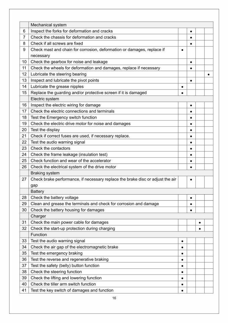
a. Maintenance checklist
Table 4: Maintenance checklist
Interval (Month)
1 3 6 12
Hydraulic
1 Check the hydraulic cylinder, piston for damage noise and leakage
2 Check the hydraulic joints and hose for damage and leakage
3 Inspect the hydraulic oil level, refill if necessary
4 Refill the hydraulic oil ( 12 month or 1500 working hours) 5 Check and adjust the function of the pressure valve (1000 kg +0/ +10%)
Battery plug
Fig.14: Battery charging
16
Mechanical system
6 Inspect the forks for deformation and cracks
7 Check the chassis for deformation and cracks
8 Check if all screws are fixed
9 Check mast and chain for corrosion, deformation or damages, replace if
necessary
10 Check the gearbox for noise and leakage
11 Check the wheels for deformation and damages, replace if necessary
12 Lubricate the steering bearing 13 Inspect and lubricate the pivot points
14 Lubricate the grease nipples
15 Replace the guarding and/or protective screen if it is damaged
Electric system
16 Inspect the electric wiring for damage
17 Check the electric connections and terminals
18 Test the Emergency switch function
19 Check the electric drive motor for noise and damages
20 Test the display
21 Check if correct fuses are used, if necessary replace.
22 Test the audio warning signal
23 Check the contactors
24 Check the frame leakage (insulation test)
25 Check function and wear of the accelerator 26 Check the electrical system of the drive motor Braking system
27 Check brake performance, if necessary replace the brake disc or adjust the air
gap
Battery
28 Check the battery voltage
29 Clean and grease the terminals and check for corrosion and damage
30 Check the battery housing for damages
Charger
31 Check the main power cable for damages
32 Check the start-up protection during charging
Function
33 Test the audio warning signal
34 Check the air gap of the electromagnetic brake
35 Test the emergency braking
36 Test the reverse and regenerative braking
37 Test the safety (belly) button function
38 Check the steering function
39 Check the lifting and lowering function
40 Check the tiller arm switch function
41 Test the key switch of damages and function

17
42 Test the speed limitation switch (lifting height >~300mm) General
43 Check if all decals are legible and complete
44 Check if the protective screen and or guarding is not damaged 45 Inspect the castor, adjust the height or replace it, if worn out 46 Carry out a test run
b. Lubricating points
Lubricate the marked points according to the maintenance checklist. The required grease specification is:
DIN 51825, standard grease.
c. Check and refill hydraulic oil
The required hydraulic fluid- type is
H-LP 46, DIN 51524
Viscosity is 41.4 - 47
Depending on the type the amount
Is 8L
Waste material like oil, used batteries or other must be probably disposed and recycled according to the
national regulations and if necessary brought to a recycling company.
The oil level height shall be in the not lifted position min.7.9L to 8.1L.
If necessary add oil at the filling point.
1 Bearings in wheels 2 Main frame post 3 Chain 4 Hydraulic system 5 Steering bearing 6 Gear box
Fig. 15: Lubricating points
18
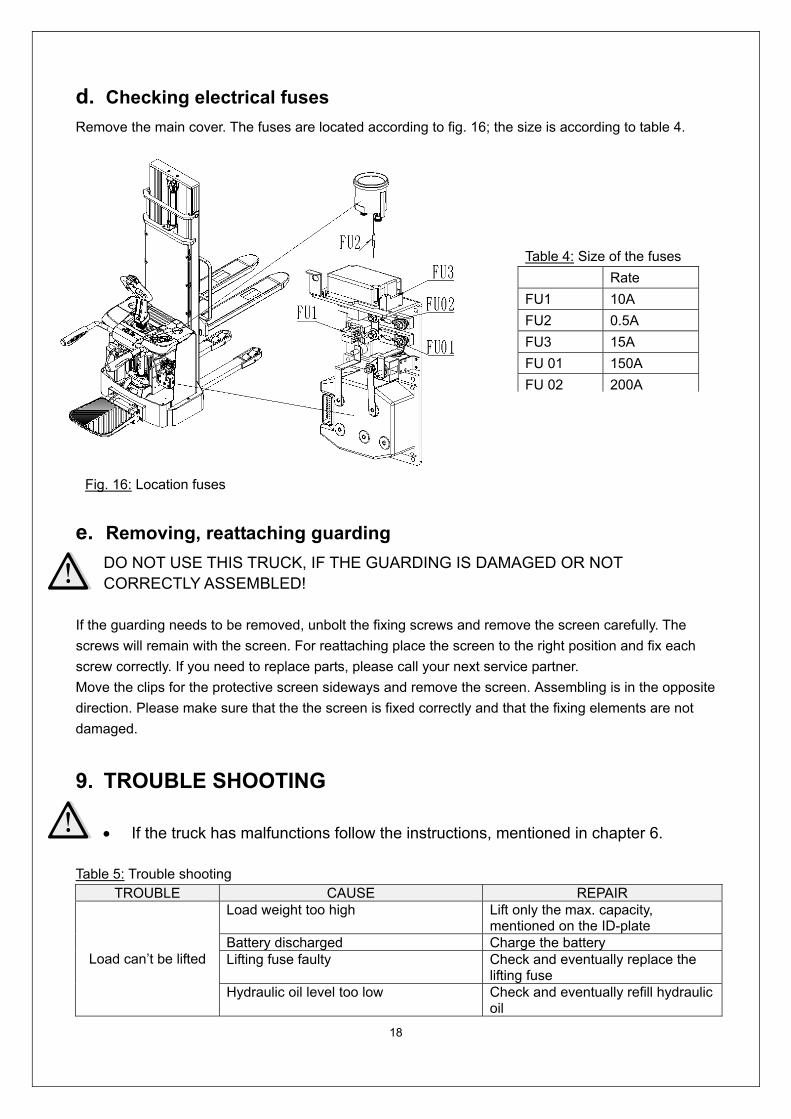
d. Checking electrical fuses
Remove the main cover. The fuses are located according to fig. 16; the size is according to table 4.
e. Removing, reattaching guarding
DO NOT USE THIS TRUCK, IF THE GUARDING IS DAMAGED OR NOT CORRECTLY ASSEMBLED!
If the guarding needs to be removed, unbolt the fixing screws and remove the screen carefully. The
screws will remain with the screen. For reattaching place the screen to the right position and fix each
screw correctly. If you need to replace parts, please call your next service partner.
Move the clips for the protective screen sideways and remove the screen. Assembling is in the opposite
direction. Please make sure that the the screen is fixed correctly and that the fixing elements are not
damaged.
9. TROUBLE SHOOTING
If the truck has malfunctions follow the instructions, mentioned in chapter 6. Table 5: Trouble shooting
TROUBLE CAUSE REPAIR
Load can’t be lifted
Load weight too high Lift only the max. capacity, mentioned on the ID-plate
Battery discharged Charge the battery Lifting fuse faulty Check and eventually replace the
lifting fuse Hydraulic oil level too low Check and eventually refill hydraulic
oil
Table 4: Size of the fuses
Rate
FU1 10A
FU2 0.5A
FU3 15A
FU 01 150A
FU 02 200A
Fig. 16: Location fuses

19
Oil leakage Repair the hoses and/or the sealing of the cylinder
Lifting stops at 1800mm Move the protective arms into the downside position
Lifting stops at 1800mm Check the sensor for the protective arm
Height sensor for 1800mm height defect Check the height sensor on the mast
Oil leakage from air breathing
Excessive quantity of oil. Reduce oil quantity.
Stacker not starts operating
Battery is charging Charge the battery completely and then remove the main power plug form the electrical socket.
Battery not connected Connect the battery correctly
The fuse is faulty Check and eventually replace fuses
Battery discharged Charge the battery
Combined emergency switch is activated
De-activate the combined emergency switch by insert and pull the knob.
Tiller in the operating zone Move the tiller firstly to the braking zone.
Protective arms in the upright position, platform folded upright
Move the protective arms into the downside position
Foldable platform or protective arms in one of the allowed positions
Check the proximate sensors for the arms and platform
Foldable platform or protective arms not in one of the allowed positions
Check the correct function of the arms and/or platform
Only travelling in one direction
The accelerator and the connections are damaged.
Check the accelerator and the connections.
The stacker only travels very slowly
The battery is discharged. Check the battery status at the discharge indicator
The electromagnetic brake is engaged. Check the electromagnetic brake
The relating tiller cables are disconnected or damaged
Check the tiller cables and connections.
Defective height sensor for reduced speed at 300mm height
Check the sensor
Electric system overheated Stop using and cool down the truck
Defective heat sensor Check and if necessary replace the heat sensor
The stacker starts up suddenly
The controller is damaged. Replace the controller. The accelerator not moves back to its neutral position.
Repair or replace the accelerator.
If the truck has malfunctions and can’t be operated out of the working zone, jack the truck up and go with
a load handler under the truck and safe the truck securely. Then move the truck out of the aisle.

20
10. WIRING/ CIRCUIT DIAGRAM
a. Electrical circuit diagram
Fig. 17: Electrical diagram
FU1 : 10A
FU2 : 0.5A
FU3 : 15A
FU 01: 150A
FU 02: 200A
21
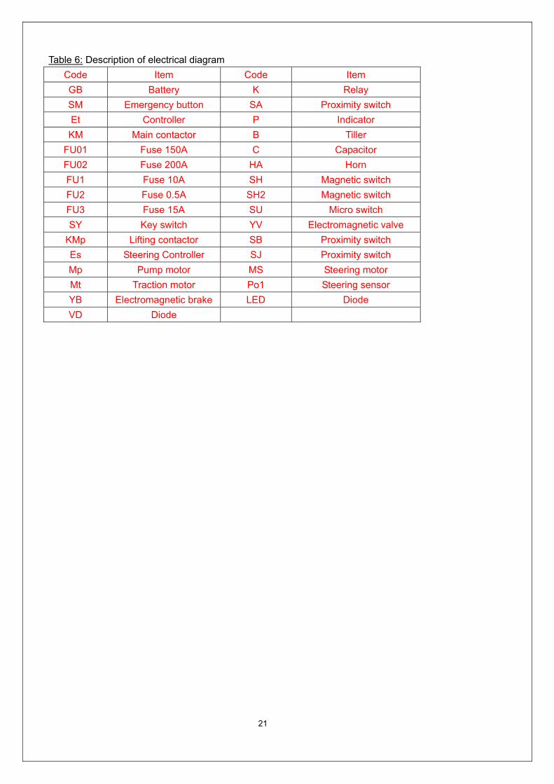
Table 6: Description of electrical diagram
Code Item Code Item
GB Battery K Relay
SM Emergency button SA Proximity switch
Et Controller P Indicator
KM Main contactor B Tiller
FU01 Fuse 150A C Capacitor
FU02 Fuse 200A HA Horn
FU1 Fuse 10A SH Magnetic switch
FU2 Fuse 0.5A SH2 Magnetic switch
FU3 Fuse 15A SU Micro switch
SY Key switch YV Electromagnetic valve
KMp Lifting contactor SB Proximity switch
Es Steering Controller SJ Proximity switch
Mp Pump motor MS Steering motor
Mt Traction motor Po1 Steering sensor
YB Electromagnetic brake LED Diode
VD Diode

22
b. Hydraulic circuit
Fig. 18: Hydraulic circuit
23
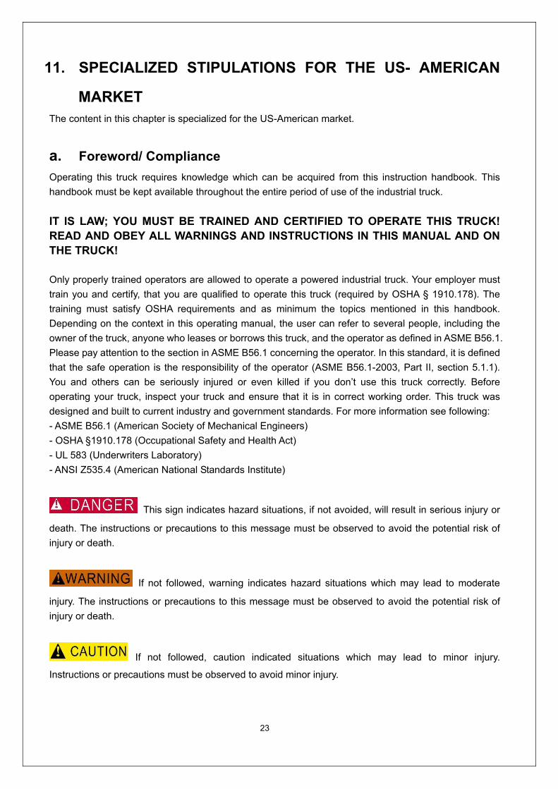
11. SPECIALIZED STIPULATIONS FOR THE US- AMERICAN
MARKET The content in this chapter is specialized for the US-American market.
a. Foreword/ Compliance
Operating this truck requires knowledge which can be acquired from this instruction handbook. This
handbook must be kept available throughout the entire period of use of the industrial truck.
IT IS LAW; YOU MUST BE TRAINED AND CERTIFIED TO OPERATE THIS TRUCK! READ AND OBEY ALL WARNINGS AND INSTRUCTIONS IN THIS MANUAL AND ON THE TRUCK! Only properly trained operators are allowed to operate a powered industrial truck. Your employer must
train you and certify, that you are qualified to operate this truck (required by OSHA § 1910.178). The
training must satisfy OSHA requirements and as minimum the topics mentioned in this handbook.
Depending on the context in this operating manual, the user can refer to several people, including the
owner of the truck, anyone who leases or borrows this truck, and the operator as defined in ASME B56.1.
Please pay attention to the section in ASME B56.1 concerning the operator. In this standard, it is defined
that the safe operation is the responsibility of the operator (ASME B56.1-2003, Part II, section 5.1.1).
You and others can be seriously injured or even killed if you don’t use this truck correctly. Before
operating your truck, inspect your truck and ensure that it is in correct working order. This truck was
designed and built to current industry and government standards. For more information see following:
- ASME B56.1 (American Society of Mechanical Engineers)
- OSHA §1910.178 (Occupational Safety and Health Act)
- UL 583 (Underwriters Laboratory)
- ANSI Z535.4 (American National Standards Institute)
This sign indicates hazard situations, if not avoided, will result in serious injury or
death. The instructions or precautions to this message must be observed to avoid the potential risk of
injury or death.
If not followed, warning indicates hazard situations which may lead to moderate
injury. The instructions or precautions to this message must be observed to avoid the potential risk of
injury or death.
If not followed, caution indicated situations which may lead to minor injury.
Instructions or precautions must be observed to avoid minor injury.

24
b. Description warning labels (only US- market)
A Crane hook label C Residual lift capacity sticke
E Identification plate(ID-plate) F Sticker to read and follow these instructions G Sign oil filling point I Sign danger being crushed
J
K
L
M
N
The truck is equipped with an emergency button (3) which stops all lifting-, lowering-, driving- functions
and engages the failsafe electromagnetic brake when it is pushed. The function is described in chapter 2c.
Follow the instructions given on the decals. Replace the decals if they are damaged or missing.
Fig. 19: Warning labels and safety devices (only USA)
Sign warning stay clear stop truck
Sign danger not riding
Sign danger battery Sign warning electrical devices
Sign not under, on forks

25
Sign read and follow this instruction (F)
Sign oil filling point (G)
Sign danger being crushed (I)
Sign warning stay clear stop truck (J)
Sign danger not riding (K)
(only if not equipped with a foldable platform)
Sign danger battery (L)
Sign warning electrical devices (M)
Sign not under, on forks(N)
26
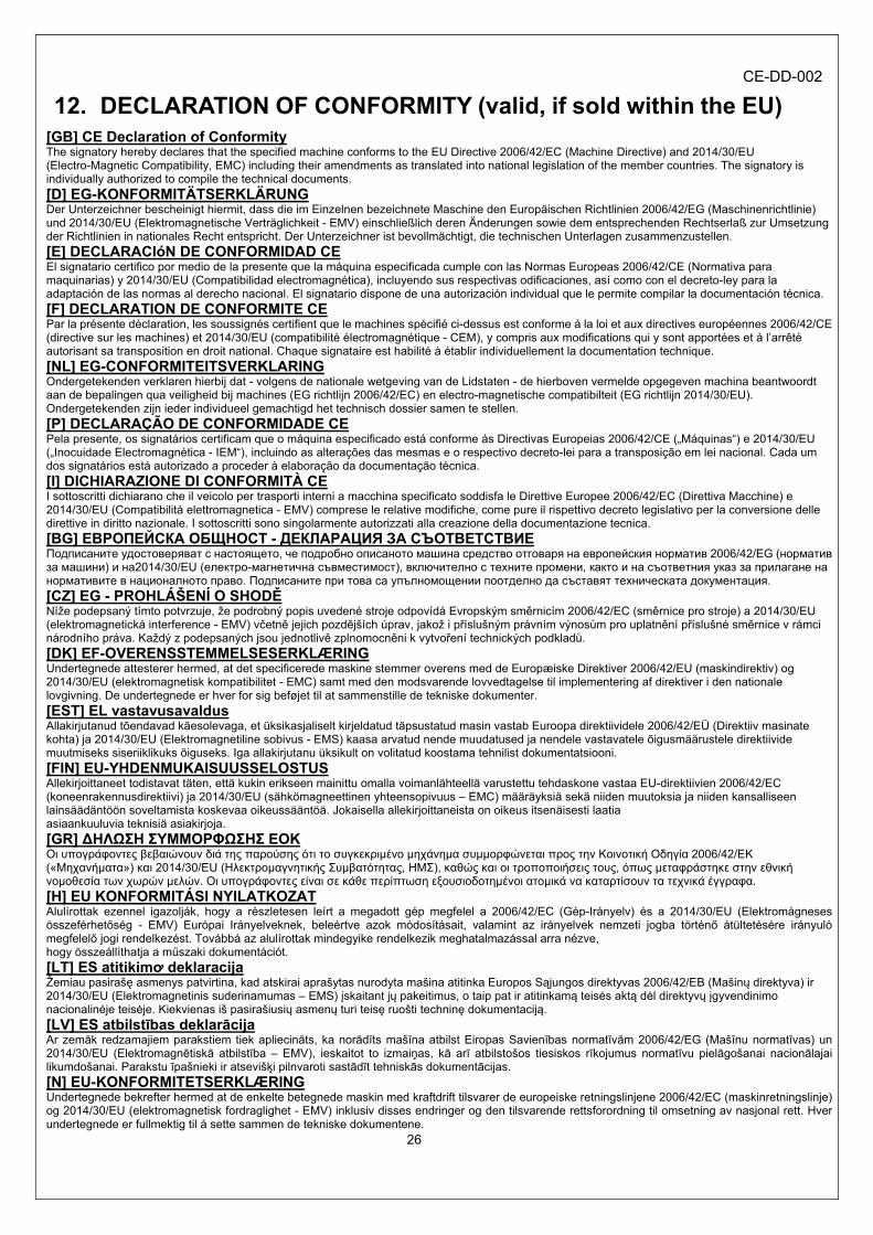
12. DECLARATION OF CONFORMITY (valid, if sold within the EU) [GB] CE Declaration of Conformity The signatory hereby declares that the specified machine conforms to the EU Directive 2006/42/EC (Machine Directive) and 2014/30/EU (Electro-Magnetic Compatibility, EMC) including their amendments as translated into national legislation of the member countries. The signatory is individually authorized to compile the technical documents.
[D] EG-KONFORMITÄTSERKLÄRUNG Der Unterzeichner bescheinigt hiermit, dass die im Einzelnen bezeichnete Maschine den Europäischen Richtlinien 2006/42/EG (Maschinenrichtlinie) und 2014/30/EU (Elektromagnetische Verträglichkeit - EMV) einschließlich deren Änderungen sowie dem entsprechenden Rechtserlaß zur Umsetzung der Richtlinien in nationales Recht entspricht. Der Unterzeichner ist bevollmächtigt, die technischen Unterlagen zusammenzustellen. [E] DECLARACIóN DE CONFORMIDAD CE El signatario certifico por medio de la presente que la máquina especificada cumple con las Normas Europeas 2006/42/CE (Normativa para maquinarias) y 2014/30/EU (Compatibilidad electromagnética), incluyendo sus respectivas odificaciones, así como con el decreto-ley para la adaptación de las normas al derecho nacional. El signatario dispone de una autorización individual que le permite compilar la documentación técnica. [F] DECLARATION DE CONFORMITE CE Par la présente déclaration, les soussignés certifient que le machines spécifié ci-dessus est conforme à la loi et aux directives européennes 2006/42/CE (directive sur les machines) et 2014/30/EU (compatibilité électromagnétique - CEM), y compris aux modifications qui y sont apportées et à l’arrêté autorisant sa transposition en droit national. Chaque signataire est habilité à établir individuellement la documentation technique. [NL] EG-CONFORMITEITSVERKLARING Ondergetekenden verklaren hierbij dat - volgens de nationale wetgeving van de Lidstaten - de hierboven vermelde opgegeven machina beantwoordt aan de bepalingen qua veiligheid bij machines (EG richtlijn 2006/42/EC) en electro-magnetische compatibilteit (EG richtlijn 2014/30/EU). Ondergetekenden zijn ieder individueel gemachtigd het technisch dossier samen te stellen. [P] DECLARAÇÃO DE CONFORMIDADE CE Pela presente, os signatários certificam que o máquina especificado está conforme às Directivas Europeias 2006/42/CE („Máquinas“) e 2014/30/EU („Inocuidade Electromagnética - IEM“), incluindo as alterações das mesmas e o respectivo decreto-lei para a transposição em lei nacional. Cada um dos signatários está autorizado a proceder à elaboração da documentação técnica.
[I] DICHIARAZIONE DI CONFORMITÀ CE I sottoscritti dichiarano che il veicolo per trasporti interni a macchina specificato soddisfa le Direttive Europee 2006/42/EC (Direttiva Macchine) e 2014/30/EU (Compatibilità elettromagnetica - EMV) comprese le relative modifiche, come pure il rispettivo decreto legislativo per la conversione delle direttive in diritto nazionale. I sottoscritti sono singolarmente autorizzati alla creazione della documentazione tecnica. [BG] EВРОПЕЙСКА ОБЩНОСТ - ДЕКЛАРАЦИЯ ЗА СЪОТВЕТСТВИЕ Подписаните удостоверяват с настоящето, че подробно описаното машина средство отговаря на европейския норматив 2006/42/EG (норматив за машини) и на2014/30/EU (електро-магнетична съвместимост), включително с техните промени, както и на съответния указ за прилагане на нормативите в националното право. Подписаните при това са упълномощении поотделно да съставят техническата документация. [CZ] EG - PROHLÁŠENÍ O SHODĚ Níže podepsaný tímto potvrzuje, že podrobný popis uvedené stroje odpovídá Evropským směrnicím 2006/42/EC (směrnice pro stroje) a 2014/30/EU (elektromagnetická interference - EMV) včetně jejich pozdějších úprav, jakož i příslušným právním výnosům pro uplatnění příslušné směrnice v rámci národního práva. Každý z podepsaných jsou jednotlivě zplnomocněni k vytvoření technických podkladů. [DK] EF-OVERENSSTEMMELSESERKLÆRING Undertegnede attesterer hermed, at det specificerede maskine stemmer overens med de Europæiske Direktiver 2006/42/EU (maskindirektiv) og 2014/30/EU (elektromagnetisk kompatibilitet - EMC) samt med den modsvarende lovvedtagelse til implementering af direktiver i den nationale lovgivning. De undertegnede er hver for sig beføjet til at sammenstille de tekniske dokumenter. [EST] EL vastavusavaldus Allakirjutanud tõendavad käesolevaga, et üksikasjaliselt kirjeldatud täpsustatud masin vastab Euroopa direktiividele 2006/42/EÜ (Direktiiv masinate kohta) ja 2014/30/EU (Elektromagnetiline sobivus - EMS) kaasa arvatud nende muudatused ja nendele vastavatele õigusmäärustele direktiivide muutmiseks siseriiklikuks õiguseks. Iga allakirjutanu üksikult on volitatud koostama tehnilist dokumentatsiooni.
[FIN] EU-YHDENMUKAISUUSSELOSTUS Allekirjoittaneet todistavat täten, että kukin erikseen mainittu omalla voimanlähteellä varustettu tehdaskone vastaa EU-direktiivien 2006/42/EC (koneenrakennusdirektiivi) ja 2014/30/EU (sähkömagneettinen yhteensopivuus – EMC) määräyksiä sekä niiden muutoksia ja niiden kansalliseen lainsäädäntöön soveltamista koskevaa oikeussääntöä. Jokaisella allekirjoittaneista on oikeus itsenäisesti laatia asiaankuuluvia teknisiä asiakirjoja.
[GR] ∆ΗΛΩΣΗ ΣΥΜΜΟΡΦΩΣΗΣ ΕΟΚ Οι υπογράφοντες βεβαιώνουν διά της παρούσης ότι το συγκεκριμένο μηχάνημα συμμορφώνεται προς την Κοινοτική Οδηγία 2006/42/ΕΚ («Μηχανήματα») και 2014/30/EU (Ηλεκτρομαγνητικής Συμβατότητας, ΗΜΣ), καθώς και οι τροποποιήσεις τους, όπως μεταφράστηκε στην εθνική νομοθεσία των χωρών μελών. Οι υπογράφοντες είναι σε κάθε περίπτωση εξουσιοδοτημένοι ατομικά να καταρτίσουν τα τεχνικά έγγραφα. [H] EU KONFORMITÁSI NYILATKOZAT Alulírottak ezennel igazolják, hogy a részletesen leírt a megadott gép megfelel a 2006/42/EC (Gép-Irányelv) és a 2014/30/EU (Elektromágneses összeférhetőség - EMV) Európai Irányelveknek, beleértve azok módosításait, valamint az irányelvek nemzeti jogba történő átültetésére irányuló megfelelő jogi rendelkezést. Továbbá az alulírottak mindegyike rendelkezik meghatalmazással arra nézve, hogy összeállíthatja a műszaki dokumentációt. [LT] ES atitikimơ deklaracija Žemiau pasirašę asmenys patvirtina, kad atskirai aprašytas nurodyta mašina atitinka Europos Sąjungos direktyvas 2006/42/EB (Mašinų direktyva) ir 2014/30/EU (Elektromagnetinis suderinamumas – EMS) įskaitant jų pakeitimus, o taip pat ir atitinkamą teisės aktą dėl direktyvų įgyvendinimo nacionalinėje teisėje. Kiekvienas iš pasirašiusių asmenų turi teisę ruošti techninę dokumentaciją.
[LV] ES atbilstības deklarācija Ar zemāk redzamajiem parakstiem tiek apliecināts, ka norādīts mašīna atbilst Eiropas Savienības normatīvām 2006/42/EG (Mašīnu normatīvas) un 2014/30/EU (Elektromagnētiskā atbilstība – EMV), ieskaitot to izmaiņas, kā arī atbilstošos tiesiskos rīkojumus normatīvu pielāgošanai nacionālajai likumdošanai. Parakstu īpašnieki ir atsevišķi pilnvaroti sastādīt tehniskās dokumentācijas. [N] EU-KONFORMITETSERKLÆRING Undertegnede bekrefter hermed at de enkelte betegnede maskin med kraftdrift tilsvarer de europeiske retningslinjene 2006/42/EC (maskinretningslinje) og 2014/30/EU (elektromagnetisk fordraglighet - EMV) inklusiv disses endringer og den tilsvarende rettsforordning til omsetning av nasjonal rett. Hver undertegnede er fullmektig til å sette sammen de tekniske dokumentene.
CE-DD-002

27
[PL] DEKLARACJA ZGODNOŚCI WE Niżej podpisani deklarują, że poniżej opisana maszyna spełnia wymagania określone w dyrektywach Europejskich 2006/42/EC (Dyrektywa Maszynowa) i 2014/30/EU (Kompatybilności elektromagnetycznej - EMC) wraz z ich późniejszymi zmianami oraz odpowiednimi rozporządzeniami mającymi na celu przeniesienie tych dyrektyw do prawa krajów członkowskich. Sygnatariusz jest indywidualnie upoważniony do zestawiania dokumentacji technicznej.
[RO] DECLARAŢIE DE CONFORMITATE CE Subsemnaţii adeveresc prin prezenta că vehiculul de specificat maşină descris individual corespunde directivelor europene 2006/42/CE (Directiva privind maşinile) şi 2014/30/EU (Compatibilitatea electromagnetică - CEM) inclusiv modificărilor lor precum şi actului legislativ corespunzător prentru transpunerea directivelor în drept naţional. Subsemnaţii sunt fiecare în parte împuterniciţi să întocmească documentaţia tehnică. [RUS] Декларация соответствия стандартам ЕС Настоящим лица, подписавшие документ, удостоверяют, что машина с указанной спецификацией соответствует европейским стандартам 2006/42/EG (Транспортная директива) и 2014/30/EU (Электромагнитная совместимость - ЕМС), включая изменения в них, а также соответствующим национальным стандартам и нормам. Каждое по отдельности лицо, подписавшее документ, имеет полномочия для составления технической документации. [S] EG-KONFORMITETSFÖRKLARING Undertecknarna intygar härmed att det i detalj betecknade maskin uppfyller de Europeiska direktiven 2006/42/EG (Maskindirektiv) och 2014/30/EU (Elektromagnetisk tålighet - EMV), inklusive ändringarna i detta och den motsvarande rättsförordningen för att omsätta direktiven i nationell rätt. Undertecknarna har var för sig fullmakt att sammanställa den tekniska dokumentationen.
[SK] vyhlásenie o zhode Dolu podpísaní týmto potvrdzujeme, že podrobný popis uvedené stroje Zodpovedá Európskym smerniciam 2006/42/EC (ernica pre stroje ) a 2014/30/EU ( elektromagnetická tolerancia – EMV ) vrátane jeho neskorších úprav, rovnako zodpovedá aj príslušným právnym nariadeniam na uplatnenie smerníc v rámci národného práva. Každý z podpísaných je jednotlivo splnomocnený na vytvorenie technických podkladov. [SLO] EU IZJAVA O SKLADNOSTI Podpisani s tem potrjujemo, da posamično označeno določeno stroj vozilo odgovarja Evropski direktivi 2006/42/EC (Direktiva o strojih) in 2014/30/EU (Elektromagnetna skladnost - EMV) vključno z njihovimi spremembami ter ustrezno pravno uredbo o prevzemu smernic v nacionalno pravo. Podpisniki so vsakokrat posamezno pooblaščeni za izdajanje tehnične dokumentacije. [TR] AB Uygunluk Açıklaması İmza sahibi şahıslar, ayrıntıları belirtilen makine aracının, 2006/42/EC (Makine Yönergesi) ve 2014/30/EU (Elektromanyetik Uyumluluk – EMC) no'lu Avrupa Yönergelerine ve bunların değişiklik sonucu oluşan metinlerine ve yönergelerin milli hukuk hükümlerine dönüştürülmesine dair ilgili hukuk kararnamesine uygun olduğunu tasdik ederler. İmza sahibi şahıslar teknik dosyaları bir araya getirmek için münferiden vekil tayin edildi.
(1) Type/ Typ/ Tipo/ Modello/ Tyyppi/ Tipo / ΤYΠΟΣ/ Típus/ Tip/ Тип/ Tips/ Tipas/ Tüüp: (2) Serial No./ Serien-Nr./ N°. de série/ Serienummer/ Nº de serie/ Numero di serie/ Serienr./ Sarjanro/ αυξάνων αριθμός/ Seriové číslo/ Szériaszám/
Nr.Seryjny/ Serijska številka/ Výrobné číslo/ Серийный номер/ Seri No./ Seerianr./ Sērijas Nr./ Serijos numeris: (3) Year of constr./ Baujahr/ Année de constr./ Bouwjaar/ Año de constr./ Anno di costruzione/ Produktionsår/ Byggeår/ Tillverkningsår/ Valmistusvuosi /
Ano de fabrico / έτος κατασκευής/ Rok výroby/ Gyártási év/ Rokprodukcji / Letnik / Год изготовления / Üretim yılı / Väljalaskeaasta / Izgatavošanas gads / Gamybosmetai
(4) Manufacturer or his authorized representative in Community/ Hersteller oder in der Gemeinschaft ansässiger Vertreter/ Fabricant ou son mandataire établi dans la Communauté/ Fabrikant of zijn in de Gemeenschap gevestigde gemachtigde/ Fabricante o representante establecido en la Comunidad/ Construtor ou Representante estabelecido na Comunidade/ Costruttore oppure il suo rappresentante nella Comunità/ Fabrikant eller dennesi Fællesskabet etablerede befuldmægtigede/ Produsent eller agent innen felleskapet/ Tillverkare eller representant inom EU/ Valmistaja tai yhteisömaassa oleva edustaja / V˘robce nebo jeho zastoupení/ Gyártó / producent albo jego przedstawiciel w EG (Wspólnota Europejska)/ Καηαζθεπαζηήο ή όκηινο ηνπηθώλ αληηπξνζώπσλ/ Üretici ya da Bölgedeki Yetkili Temsilci/ Proizvajalec ali pooblaščeni zastopnik s sedežem v EU/ Výrobca alebo zástupca so stálym bydliskom v EÚ / Изготовитель или его представитель, зарегистрированный в стране Содружества/ Tootja või organisatsioonis paiknev esindaja/ Ražotājs vai vietējais uzņēmuma pārstāvis / Gamintojas arba šalyje reziduojantis atstovas:
(5) Date/ Datum/ Data/ Fecha/ datum/ Dato/ päiväys/ Kuupäev/ Datums/дата / Dátum/ dátum/ tarih/ ημερομηνία (6) Authorised signatory/ Im Auftrag/ pour ordre/ Incaricato/ Por orden de/ por procuração/ op last van/ på vegne af/ på uppdrag/ Etter oppdrag/ psta./
Ülesandel / pavedus / v.i. / По поручению / megbízásából /длъжностно лице / z pověření / z poverenia / po nalogu / na polecenie / din sarcina / adına / θαη' εληνιή
(1) Type: XX XX – Self propelled industrial truck
(2) Serial No: XXXXXXXX
(3) Year of constr.: YYYY
(4) Manufacturer or his authorized representative in Community:
Company name/ Street / Postal code Town/ Country
(5) Date: YYYY. MM.DD
(6) Authorized signatory: Mr. Sample