Instruction Bulletin - Schneider Electric · 2014-01-18 · 1 Instruction Bulletin 48049-184-03...
12
1 Instruction Bulletin 48049-184-03 08/2004 Cedar Rapids, IA, USA ECN 656B Hand-Held Test Kit for Micrologic ® Series 2.0 and Above Trip Units and Compact ® NS Circuit Breakers Equipped with STR Trip Units Retain for future use. © 2000–2004 Schneider Electric All Rights Reserved ENGLISH IDENTIFICATION Figure 1: Hand-held Test Kit B C D E F G A N M L K J H O I A— Battery Compartment (five 9.0 V) B— Short-circuit Trip LED (red) C—Ground-fault Trip LED (red) D—Ground-fault Inhibit LED (green) E— Thermal-imaging Inhibit LED (green) F— Trip Unit Power Supply LED (green) G—Low Battery LED (amber) H— Good Battery LED (green) I— Trip Unit Test Cable 10-pin Port J— 9 V Battery Test Button K—Trip Unit Power Supply Button L— Thermal-imaging Inhibit Button M—Ground-fault Inhibit Button N—Ground-fault Trip Button O—Short-circuit Trip Button 06133786 Figure 2: Hand-held Test Kit Accessories 2-pin Test Cable for STR Trip Units 7-pin Test Cable for Micrologic ® Trip Units Primary Injection Adapter 06133771 06133770 06135367
Transcript of Instruction Bulletin - Schneider Electric · 2014-01-18 · 1 Instruction Bulletin 48049-184-03...

1
Instruction Bulletin
48049-184-03
08/2004
Cedar Rapids, IA, USA
ECN 656B
Hand-Held Test Kitfor Micrologic® Series 2.0 and Above Trip Units and Compact® NS Circuit Breakers Equipped with STR Trip Units
Retain for future use.
© 2000–2004 Schneider Electric All Rights Reserved
EN
GL
ISH
IDENTIFICATION
Figure 1: Hand-held Test Kit
B
C
D
E
F
G
A
N
M
L
K
J
H
O
I
A— Battery Compartment (five 9.0 V)
B— Short-circuit Trip LED (red)
C—Ground-fault Trip LED (red)
D—Ground-fault Inhibit LED (green)
E— Thermal-imaging Inhibit LED (green)
F— Trip Unit Power Supply LED (green)
G—Low Battery LED (amber)
H—Good Battery LED (green)
I— Trip Unit Test Cable 10-pin Port
J— 9 V Battery Test Button
K— Trip Unit Power Supply Button
L— Thermal-imaging Inhibit Button
M—Ground-fault Inhibit Button
N—Ground-fault Trip Button
O—Short-circuit Trip Button
0613
3786
Figure 2: Hand-held Test Kit Accessories
2-pin Test Cable for STR Trip Units 7-pin Test Cable for Micrologic® Trip Units Primary Injection Adapter
061
3377
1
061
3377
0
0613
5367

Hand-Held Test Kit 48049-184-03
08/2004
© 2000–2004 Schneider Electric All Rights Reserved2
EN
GL
ISH
BATTERY INSTALLATION NOTE: The Hand-held Test Kit uses five 9.0 V alkaline batteries (not
supplied). Recommended battery is Panasonic Industrial Alkaline 9 V, part
number 6AM-6PIX/1S, or equivalent. Do not use nickel metal hydride, NiCd,
manganese or lithium batteries as damage can result to the internal circuitry
of the Hand-held Test Kit.
NOTE: There are no repairable internal parts for the Hand-held Test Kit.
Housing should only be opened to install or replace batteries.
DETERMINE TRIP UNIT COMPATIBILITY Refer to Table 1 to determine which tests and functions are applicable then
follow appropriate connection procedures. Read this instruction bulletin
in its entirety before initiating any test or function.
CAUTION
HAZARD OF EQUIPMENT DAMAGE
This equipment uses five 9.0 V alkaline
batteries only. Do not use nickel metal hydride,
NiCd, manganese or lithium batteries.
Failure to follow this instruction can result in
damage to the internal circuitry of this
equipment.
1. Remove six screws (A).
2. Separate front housing (B) of Hand-held Test Kit from back housing (C).
3. Carefully remove battery circuit board (D).
4. If replacing batteries, remove old batteries.
5. Insert new batteries (E) making sure polarity is correct.
6. Carefully install battery circuit board (D).
7. Attach back housing (C) of Hand-held Test Kit to front housing (B) using
six previously removed tapping screws (A).
Figure 3: Battery Installation
06
1337
94
A
B
C
D
E3.13 lb-in
(0.35 N•m)
Table 1: Trip Unit Compatibility*
Trip Unit TypeTest
Cable
Test Functions Inhibit FunctionsTrip Unit
Power
Supply
Battery
TestShort-
circuit
Trip
Ground-
fault Trip
Ground-
fault
Inhibit
Thermal-
imaging
Inhibit
Non-communicating
STR22, STR23, STR43 2-pin Test Cable
t t
STR53 t t t
ET1.0I, ET 1.0M
7-pin Test Cable
t t
Micrologic 2.0, 3.0, 5.0 t t
CommunicatingMicrologic 2.0A, 3.0A, 5.0A, 5.0P, 5.0H t t t t
Micrologic 6.0A, 6.0P, 6.0H, 7.0A, 7.0P, 7.0H t t t t t
No Trip Unit Connected2- or 7-pin Test Cable
t
*If a non-supported test or inhibit function is initiated on a trip unit, an error message will appear and circuit breaker may trip.

48049-184-03 Hand-Held Test Kit
08/2004
© 2000–2004 Schneider Electric All Rights Reserved 3
EN
GL
ISH
CONNECTIONS NOTE: Trip unit must be installed in circuit breaker in order to properly
execute Hand-held Test Kit tests and inhibit functions.
Compact® NS Circuit Breakers Equipped
with STR Trip Units
1. Connect test cable 10-pin connector (A) to 10-pin port on Hand-held
Test Kit.
2. Connect test cable 2-pin connector (B) to test port on STR trip units.
Make sure to observe correct polarity.
NOTE: Refer to Ground-fault Trip Test for proper ground-fault connection.
Micrologic® Trip Units
Short-circuit Trip Test 1. Connect test cable 10-pin connector (A) to 10-pin port on Hand-held
Test Kit.
2. Connect test cable 7-pin connector (B) to test port on Micrologic trip
units. Refer to instruction label on test cable for connection instructions.
Figure 4: Connection to STR Trip Units
ImI0 Ir
test
+ -
test
+ -
+ -
+-
Test Test Test
Disparo cortocircuito
Déclenchement court-circuitShort-circuit trip
Déclenchement protection terreGround-fault tripDisparo proteccion de tierra
Inhibiton Inhibit SuprecionProtection terreGround faultProteccion de tierra
Mémoire thermiqueThermal imagingProteccion de tierra
Alimentation déclencheurTrip unit power supplyAlimentacion del disparador
9 V - Battery test
Test Kit
33594
B
A
0613
3797
Figure 5: Connection to Micrologic Trip Units for Short-circuit Trip
Test
Micrologic 2.0
+-
Test Test Test
Disparo cortocircuito
Déclenchement court-circuitShort-circuit trip
Déclenchement protection terreGround-fault tripDisparo proteccion de tierra
Inhibiton Inhibit SuprecionProtection terreGround faultProteccion de tierra
Mémoire thermiqueThermal imagingProteccion de tierra
Alimentation déclencheurTrip unit power supplyAlimentacion del disparador
9 V - Battery test
Test Kit
33594
B
A
0613
3796

Hand-Held Test Kit 48049-184-03
08/2004
© 2000–2004 Schneider Electric All Rights Reserved4
EN
GL
ISH
Inhibit Functions and Trip Unit Power Supply 1. Connect primary injection test adapter 10-pin connector (A) to 10-pin
port on Hand-held Test Kit.
2. Connect test cable 10-pin connector (B) to 10-pin port on primary
injection test adapter.
3. Connect test cable 7-pin connector (C) to test port on Micrologic trip
units. Refer to instruction label on test cable for connection instructions.
Error Message Indication An error message is indicated by all LEDs lighting at once. If an error
message is displayed during Hand-held Test Kit operation, check all
connections then refer to Table 1 and Troubleshooting section.
Figure 6: Connection to Micrologic Trip Units for Inhibit Functions
and Trip Unit Power
Micrologic 2.0
+-
Test Test Test
Disparo cortocircuito
Déclenchement court-circuitShort-circuit trip
Déclenchement protection terreGround-fault tripDisparo proteccion de tierra
Inhibiton Inhibit SuprecionProtection terreGround faultProteccion de tierra
Mémoire thermiqueThermal imagingProteccion de tierra
Alimentation déclencheurTrip unit power supplyAlimentacion del disparador
9 V - Battery test
Test Kit
33594
A
B
C
06
1353
46

48049-184-03 Hand-Held Test Kit
08/2004
© 2000–2004 Schneider Electric All Rights Reserved 5
EN
GL
ISH
TESTS
Short-circuit Trip Test This test verifies operation of trip unit short-circuit protection function. The
Hand-held Test Kit supplies power to trip unit while injecting a secondary
fault signal large enough to cause tripping of circuit breaker. For Micrologic
A trip units only, performing this test will reset to zero the maximum
recorded value on each phase. If necessary, record maximum values before
testing.
NOTE: Short-circuit tests will not be recorded in trip log of Micrologic P and
H trip units. Advanced protection and alarms will also be disabled during
test. Refer to trip unit instruction bulletin for advanced protection features.
1. Close circuit breaker being tested. Use a properly rated voltage sensing
device to verify circuit breaker is not carrying current.
2. Press short-circuit trip button (A).
a. For non-communicating trip units (see Table 1), the red short-circuit
trip LED will light solid indicating short-circuit trip test is in progress.
b. For communicating trip units (see Table 1), the red short-circuit trip
LED will flicker indicating communication activity with the trip unit
while short-circuit trip test is in progress.
NOTE: All LEDs lighting at once indicates Hand-held Test Kit cannot
establish communication with trip unit. The trip unit gives communication
priority to the circuit breaker communications module (BCM). When
BCM is powered and operating, its communication activities take
precedence over Hand-held Test Kit commands. After all LEDs go out,
repeat step 2. If all LEDs light up again, disconnect power from E1 and
E2 terminals of BCM and repeat step 2.
3. Confirm test was successful by verifying circuit breaker tripped. Refer to
circuit breaker and trip unit instruction bulletins for proper circuit breaker
operation.
4. For communicating trip units wait for test exit communication, indicated
by flickering red short-circuit trip LED, before disconnecting Hand-held
Test Kit.
5. Test exit communication is complete when red short-circuit trip LED
turns off automatically with no error display.
DANGERHAZARD OF ELECTRIC SHOCK,
EXPLOSION OR ARC FLASH
• Apply appropriate personal protective
equipment (PPE) and follow safe electrical
work practices. See NFPA 70E
• This equipment must be installed and
serviced only by qualified electrical
personnel.
• Turn off all power supplying this equipment
before working on or inside equipment.
• Always use a properly rated voltage sensing
device to confirm power is off.
• Replace all devices, doors and covers before
turning on power to this equipment.
Failure to follow this instruction will result in
death or serious injury.
Figure 7: Short-circuit Trip Button
A
06
1337
88

Hand-Held Test Kit 48049-184-03
08/2004
© 2000–2004 Schneider Electric All Rights Reserved6
EN
GL
ISH
Ground-fault Trip Test The Hand-held Test Kit can be used to verify ground-fault protection for
STR53 trip units only.
NOTE: To test ground-fault trip on Micrologic 6.0P, 6.0H, 7.0P and 7.0H trip
units, press test button located directly above trip unit test port. To prevent
logging of ground-fault trip test in trip unit’s trip history, use Hand-held Test
Kit to inhibit thermal-imaging, as described in this instruction bulletin.
1. Close circuit breaker being tested. Use a properly rated voltage sensing
device to verify circuit breaker is not carrying current.
2. Make sure to reverse the polarity of 2-pin test cable connection as
shown in Figure 8.
CAUTION
HAZARD OF INVALID READING
Make sure to reverse the polarity of 2-pin test
cable before performing ground-fault trip test.
Failure to follow this instruction can result in
inaccurate test results.
Figure 8: Reverse Polarity
ImI0 Ir
test
+ -
test
+ -
+-
0613
3798
Figure 9: Ground-fault Trip Button
A
061
3378
9
3. Press ground-fault trip button (A). The red ground-fault trip LED will light
solid indicating ground-fault trip test is in progress.
4. Confirm test was successful by verifying circuit breaker tripped. Refer to
circuit breaker and trip unit instruction bulletins for proper circuit breaker
operation.
5. Once ground-fault trip test is successfully completed, red ground-fault
trip LED turns off automatically with no error display.
48049-184-03 Hand-Held Test Kit
08/2004
© 2000–2004 Schneider Electric All Rights Reserved 7
EN
GL
ISH
INHIBIT FUNCTIONS Inhibit functions are only available during long-time, short-time,
instantaneous and ground-fault (LSIG) primary-injection testing of certain
communicating Micrologic trip units (see Table 1). For Micrologic P and H
trip units, inhibit functions disable advanced protection, alarms and logging
of events during testing. Refer to trip unit instruction bulletin for advanced
protection features.
Ground-fault Inhibit NOTE: Activating ground-fault inhibit will automatically activate thermal-
imaging inhibit and enable zone-selective interlocking (ZSI) self-restraint.
1. Make sure primary injection adapter is connected as shown in Figure 6.
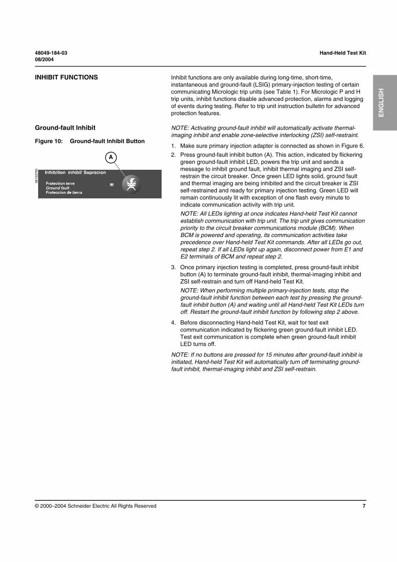
2. Press ground-fault inhibit button (A). This action, indicated by flickering
green ground-fault inhibit LED, powers the trip unit and sends a
message to inhibit ground fault, inhibit thermal imaging and ZSI self-
restrain the circuit breaker. Once green LED lights solid, ground fault
and thermal imaging are being inhibited and the circuit breaker is ZSI
self-restrained and ready for primary injection testing. Green LED will
remain continuously lit with exception of one flash every minute to
indicate communication activity with trip unit.
NOTE: All LEDs lighting at once indicates Hand-held Test Kit cannot
establish communication with trip unit. The trip unit gives communication
priority to the circuit breaker communications module (BCM). When
BCM is powered and operating, its communication activities take
precedence over Hand-held Test Kit commands. After all LEDs go out,
repeat step 2. If all LEDs light up again, disconnect power from E1 and
E2 terminals of BCM and repeat step 2.
3. Once primary injection testing is completed, press ground-fault inhibit
button (A) to terminate ground-fault inhibit, thermal-imaging inhibit and
ZSI self-restrain and turn off Hand-held Test Kit.
NOTE: When performing multiple primary-injection tests, stop the
ground-fault inhibit function between each test by pressing the ground-
fault inhibit button (A) and waiting until all Hand-held Test Kit LEDs turn
off. Restart the ground-fault inhibit function by following step 2 above.
4. Before disconnecting Hand-held Test Kit, wait for test exit
communication indicated by flickering green ground-fault inhibit LED.
Test exit communication is complete when green ground-fault inhibit
LED turns off.
NOTE: If no buttons are pressed for 15 minutes after ground-fault inhibit is
initiated, Hand-held Test Kit will automatically turn off terminating ground-
fault inhibit, thermal-imaging inhibit and ZSI self-restrain.
Figure 10: Ground-fault Inhibit Button
A
06
1337
90

Hand-Held Test Kit 48049-184-03
08/2004
© 2000–2004 Schneider Electric All Rights Reserved8
EN
GL
ISH
Thermal-imaging Inhibit Thermal imaging provides continuous temperature rise status of circuit
breaker cabling both before and after a device trips. Under normal
conditions a 15-minute delay is required following a device tripping to allow
system to cool before returning to normal functionality. The thermal-imaging
inhibit function inhibits thermal imaging, thus overriding the 15-minute delay
and allowing for multiple consecutive primary injection tests.
NOTE: Activating thermal-imaging inhibit will automatically enable zone-
selective interlocking (ZSI) self-restraint. However, activating thermal-
imaging inhibit will not automatically activate ground-fault inhibit.
1. Make sure primary injection adapter is connected as shown in Figure 6.
2. Press thermal-imaging inhibit button (A). This action, indicated by
flickering green thermal-imaging inhibit LED, powers trip unit and sends
a message to inhibit thermal imaging and ZSI self-restrain the circuit
breaker. Once green LED lights solid, thermal imaging is being inhibited
and the circuit breaker is ZSI self-restrained and ready for primary
injection testing. Green LED will remain continuously lit with exception of
one flash every minute to indicate communication activity with trip unit.
NOTE: All LEDs lighting at once indicates Hand-held Test Kit cannot
establish communication with trip unit. The trip unit gives communication
priority to the circuit breaker communications module (BCM). When
BCM is powered and operating, its communication activities take
precedence over Hand-held Test Kit commands. After all LEDs go out,
repeat step 2. If all LEDs light up again, disconnect power from E1 and
E2 terminals of BCM and repeat step 2.
3. Once primary injection testing is completed, press thermal-imaging
inhibit button (A) to terminate thermal-imaging inhibit and ZSI self-
restrain and turn off Hand-held Test Kit.
NOTE: When performing multiple primary-injection tests, stop the
thermal-imaging inhibit function between each test by pressing the
thermal-imaging inhibit button (A) and waiting until all Hand-held Test Kit
LEDs turn off. Restart the thermal-imaging inhibit function by following
step 2 above.
4. Before disconnecting Hand-held Test Kit, wait for test exit
communication indicated by flickering green thermal-imaging inhibit
LED. Test exit communication is complete when green thermal-imaging
inhibit LED turns off.
NOTE: If no buttons are pressed for 15 minutes after thermal-imaging inhibit
is initiated, Hand-held Test Kit will automatically turn off terminating thermal-
imaging inhibit and ZSI self-restrain.
Figure 11: Thermal-imaging Inhibit Button
A
06133
791

48049-184-03 Hand-Held Test Kit
08/2004
© 2000–2004 Schneider Electric All Rights Reserved 9
EN
GL
ISH
TRIP UNIT POWER SUPPLY The Hand-held Test Kit provides power to communicating Micrologic trip
units (see Table 1) to allow setup and testing. It can also be used in
conjunction with the Full-function Test Kit to verify functionality of zone-
selective interlocking (ZSI). In this application, the Hand-held Test Kit
provides power to an upstream trip unit while the Full-function Test Kit
performs ZSI test.
1. Make sure primary injection adapter is connected as shown in Figure 6.
2. Press trip unit power supply button (A). The green trip unit power supply
LED will light solid indicating Hand-held Test Kit is providing power to
trip unit.
3. Once any setup or testing functions are complete, press trip unit power
supply button (A) to terminate power to trip unit and to turn off Hand-held
Test Kit.
4. Before disconnecting Hand-held Test Kit, make sure green trip unit
power supply LED turns off.
NOTE: If no buttons are pressed for 15 minutes after trip unit power supply
function is initiated, Hand-held Test Kit will automatically turn off and power
to trip unit will be terminated.
BATTERY TEST This function tests voltage of Hand-held Test Kit’s batteries.
1. Press 9 V-battery test button (A).
2. Both LEDs will light followed by one of the following:
— Solid green LED indicates good batteries.
— Solid amber LED indicates low batteries.
NOTE: Both LEDs off indicates exhausted batteries or batteries not
installed.
Figure 12: Trip Unit Power Supply Button
A
06133
792
Figure 13: Battery Test Button
A
0613
3793

Hand-Held Test Kit 48049-184-03
08/2004
© 2000–2004 Schneider Electric All Rights Reserved10
EN
GL
ISH
TROUBLESHOOTING
Table 2: Troubleshooting
Condition Probable Causes Solutions
General
Pressed any button and no LEDs turned on.
1. Exhausted batteries or batteries not installed.
2. Defective Hand-held Test Kit.
1. Install fresh batteries and press battery test button.
2. Contact local field office.
Pressed either test button, red LED turned on and then off; circuit breaker did not trip.
1. Circuit breaker not properly reset.2. Loose test cable connections between Hand-
held Test Kit and trip unit.3. Defective Hand-held Test Kit, trip unit or
circuit breaker.
1. Verify circuit breaker is reset and closed.2. Check test cable connections and restart
test.3. Contact local field office.
Pressed any test or inhibit function button, all LEDs turned on and then off; circuit breaker did not trip.
1. Loose or no test cable connections between Hand-held Test Kit and trip unit.
2. Test attempted not applicable to trip unit type.
3. Circuit breaker communication module (BCM) is in active communicating mode.
4. Defective Hand-held Test Kit, trip unit or circuit breaker.
1. Check test cable connections and restart test.
2. Refer to Table 1 to determine if test is applicable to trip unit type.
3. Wait a few seconds and restart test or disconnect power from E1 and E2 terminals on circuit breaker communications module.
4. Contact local field office.
Pressed any test or inhibit function button and after one minute of duration all LEDs turned on and then off.
Communication error occurred while test in progress.
Wait a few seconds and restart test or disconnect power from E1 and E2 terminals on circuit breaker communications module.
Pressed any test or inhibit function button and after LED flickered all LEDs turned on and then off.
Circuit breaker communication module (BCM) in active communicating mode.
Wait a few seconds and restart test or disconnect power from E1 and E2 terminals on circuit breaker communications module.
Short-circuit trip test
Pressed short-circuit trip test button, red LED turned on and then off; circuit breaker did not trip.
1. Circuit breaker not properly reset.2. Primary injection adapter connected.3. Loose test cable connections between Hand-
held Test Kit and trip unit.4. Circuit breaker communication module
(BCM) in active communicating mode.
5. Defective Hand-held Test Kit, trip unit or circuit breaker.
1. Verify circuit breaker is reset.2. Disconnect primary injection adapter.3. Check test cable connections and restart
short-circuit trip test.4. Wait a few seconds and restart test or
disconnect power from E1 and E2 terminals on circuit breaker communications module.
5. Contact local field office.
Pressed Short-circuit trip test button, red LED turned on followed by all LEDs turning on and then off; circuit breaker did not trip.
1. No test cable connections between Hand-held Test Kit and trip unit.
2. Communication error with communicating MICROLOGIC trip unit.
3. Circuit breaker communication module (BCM) in active communicating mode.
1. Check test cable connections.
2. Check test cable connections and restart short-circuit trip test.
3. Wait a few seconds and restart test or disconnect power from E1 and E2 terminals on circuit breaker communications module.
Ground-fault trip test
Pressed ground-fault trip test button, red LED turned on and then off; circuit breaker did not trip.
1. Polarity on 2-pin test cable not reversed.
2. Circuit breaker not properly reset.3. Primary injection adapter connected.4. Loose test cable connections between Hand-
held Test Kit and trip unit.5. Defective Hand-held Test Kit, trip unit or
circuit breaker.
1. Reverse polarity on 2-pin test cable connection.
2. Verify circuit breaker is reset.3. Disconnect primary injection adapter.4. Check test cable connections and restart
short-circuit trip test.5. Contact local field office.
Pressed ground-fault trip test button, red LED turned on followed by all LEDs turning on and then off; circuit breaker did not trip.
1. No test cable connections between Hand-held Test Kit and trip unit.
2. Ground-fault trip test not applicable to trip unit type.
1. Check test cable connections and restart ground-fault trip test.
2. Refer to Table 1 to determine if ground-fault trip test is applicable to trip unit type.
Continued on next page

48049-184-03 Hand-Held Test Kit
08/2004
© 2000–2004 Schneider Electric All Rights Reserved 11
EN
GL
ISH
Ground-fault inhibit function
Pressed ground-fault inhibit button and green LED turned on followed by all LEDs turning on and then off.
1. Loose or no test cable connections between Hand-held Test Kit and trip unit.
2. Communication error with communicating MICROLOGIC trip unit.
3. Ground-fault inhibit function not applicable to trip unit type.
4. Circuit breaker communication module (BCM) in active communicating mode.
5. Defective Hand-held Test Kit, trip unit or circuit breaker.
1. Check test cable connections and restart ground-fault inhibit function.
2. Check test cable connections and restart ground-fault inhibit function.
3. Refer to Table 1 to determine if ground-fault inhibit function is applicable to trip unit type.
4. Wait a few seconds and restart test or disconnect power from E1 and E2 terminals on circuit breaker communications module.
5. Contact local field office.
Circuit breaker trips on ground fault, but Hand-held Test Kit indicates it is inhibiting ground fault (i.e., green ground-fault inhibit LED is on).
During multiple primary-injection tests, ground-fault inhibit was not stopped and then restarted between each test.
When performing multiple primary-injection tests, stop ground-fault inhibit function between each test by pressing ground-fault inhibit button and waiting until all Hand-held Test Kit LEDs turn off. Restart ground-fault inhibit function for next primary-injection test.
Thermal-imaging inhibit function
Pressed thermal-imaging inhibit button and green LED turned on followed by all LEDs turning on and then off.
1. Loose or no test cable connections between Hand-held Test Kit and trip unit.
2. Communication error with communicating MICROLOGIC trip unit.
3. Thermal-imaging inhibit function not applicable to trip unit type.
4. Circuit breaker communication module (BCM) in active communicating mode.
5. Defective Hand-held Test Kit, trip unit or circuit breaker.
1. Check test cable connections and restart thermal-imaging inhibit function.
2. Check test cable connections and restart thermal-imaging inhibit function.
3. Refer to Table 1 to determine if thermal-imaging inhibit function is applicable to trip unit type.
4. Wait a few seconds and restart test or disconnect power from E1 and E2 terminals on circuit breaker communications module.
5. Contact local field office.
Circuit breaker trips earlier than expected.
During multiple primary-injection tests, thermal-imaging inhibit was not stopped and then restarted between each test.
When performing multiple primary-injection tests, stop thermal-imaging inhibit function between each test by pressing thermal-imaging inhibit button and waiting until all Hand-held Test Kit LEDs turn off. Restart thermal-imaging inhibit function for next primary-injection test.
Trip unit power supply
Pressed trip unit power supply button and green LED turned on followed by all LEDs turning on and then off.
1. No test cable connections between Hand-held Test Kit and trip unit.
2. Trip unit power supply function not applicable to trip unit type.
1. Check test cable connections and restart trip unit power supply function.
2. Refer to Table 1 to determine if trip unit power supply function is applicable to trip unit type.
Battery testPressed any button and solid yellow LED turned on and then off.
1. Low batteries. 1. Install fresh batteries and press battery test button.
Table 2: Troubleshooting (continued)
Condition Probable Causes Solutions
4. Circuit breaker communication module (BCM) in active communicating mode.
Pressed thermal-imaging inhibit button Pressed thermal-imaging inhibit button and green LED turned on followed by all LEDs turning on and then off.
4. Wait a few seconds and restart test or disconnect power from E1 and E2 terminals

Hand-Held Test Kit 48049-184-03
Instruction Bulletin 08/2004
EN
GL
ISH
Electrical equipment should be installed, operated, serviced, and maintained only by
qualified personnel. No responsibility is assumed by Schneider Electric for any
consequences arising out of the use of this material.
Schneider Electric USA
3700 Sixth St SW, PO Box 3069
Cedar Rapids, IA 52406-3069 USA
1-888-SquareD (1-888-778-2733)
www.us.SquareD.com
© 2000–2004 Schneider Electric All Rights Reserved12